

Intermatic T10000R SERIES Installation, Operation & Service Manual

INSTALLATION
OPERATION &
T10000R SERIES
POOL/SPA EQUIPMENT CONTROLS
SERVICE MANUAL
CONTROL PANEL WITH TIME SWITCH FOR INDOOR/OUTDOOR USE
Suitable for Pool Equipment Control and for Direct Connection of Underwater Lights
ELECTRICAL RATINGS: See inside Enclosure Door
DANGER! TO AVOID RISK OF INJURY:
...do not permit children to operate the Control Unit or use the Pool/Spa unless they are closely supervised at all times.
...test GROUND FAULT protection regularly. If it fails to reset, DO NOT USE THE POOL or SPA!
Contact a qualified service technician.
...always disconnect electricity before servicing this control or the equipment connected to it.
READ, FOLLOW AND SAVE THIS INSTRUCTION MANUAL
GENERAL INFORMATION
Many of today’s energy efficient pools and spas
utilize the advantages of a single electrical panel,
containing all the necessary controls for the safe,
efficient and automatic operation of the pool/spa
equipment. In addition, this Panel can also be
used to control any outdoor equipment, sign or
pump within its rated capacity.
The all-weather enclosure contains none one or
two heavy-duty, industrial grade Time Switches.
Also, it has provisions to install switches inside
as well as a switch or GFCI receptacle on the
outside.
The Time Switch can also accommodate an
optional heater control (fireman) switch.
The Control is designed to operate any pump,
within its rated capacity. However, if protection
to prevent dry start is required by the pump
manufacturer, it must be provided in addition
to this Control. Contact pump manufacturer
if not sure and/or for more details.
1
IMPORTANT SAFETY INSTRUCTIONS
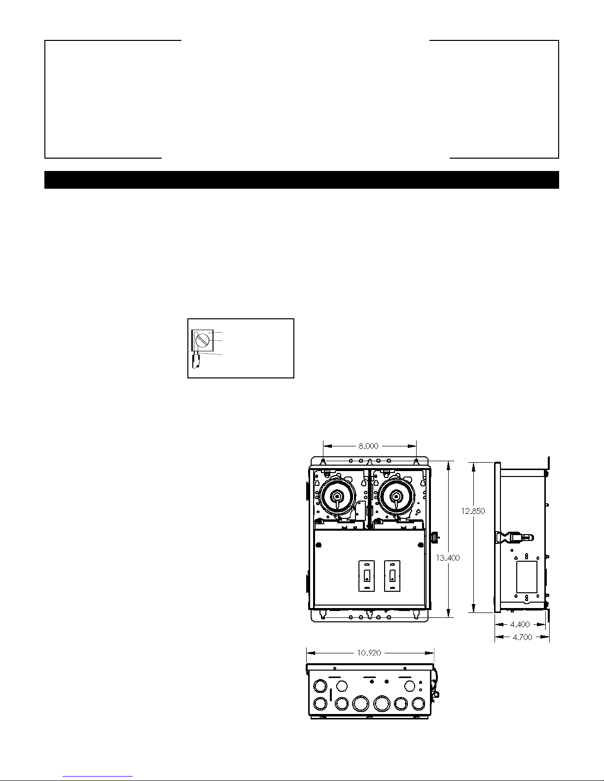
PRESSURE PLATE
TERMINAL SCREW
MAKE SURE INSULATION
CLEARS PRESSURE PLATE
When installing and operating this Product and other associated equipment, basic safety precautions should always be followed,
including the following:
1. Read and follow all instructions.
2. This Control must be installed by a qualified electrician, according to National and Local Electrical Codes.
3. Install this control not less than 5 feet (3 meters in Canada) from inside edge of pool. USE COPPER CONDUCTORS ONLY.
4. Do not exceed the maximum ratings of individual components, wiring devices, and current carrying capacity of conductors.
5. For Control grounding, bonding, installing and the wiring of underwater lights, refer to Article 680 of the National Electrical
Code or Article 68 of the Canadian Electrical Code.
6. The Control should not operate any equipment which would cause bodily injury or property damage should it be activated unexpectedly.
READ, FOLLOW AND SAVE THIS INSTRUCTION MANUAL
INSTALLATION
1. Remove the four #10 hex head screws from the
back of the enclosure and attach mounting brackets
to enclosure.
2. Select the proper location for the Control and hang
enclosure on a flat vertical surface or other support,
using hardware suitable for the purpose.
3. Prepare the necessary conduit runs, terminate them
at both ends and pull in the conductors as specified
by the installation layout.
4. Refer to Figure 1 below;
note that this enclosure
contains one or two Time
Switch(es). To wire the
panel, follow the wiring diagram located inside the
enclosure door. Make sure that connections to time
switch terminals are tight (25 lb.-in. minimum) and
insulation clears the pressure plate - see illustration.
5. If required by the heater manufacturer, install
fireman switch kit 156T4042A (not furnished)
on Time Switch Plate and make the fireman switch
connections. Use at least #18 AWG wiring with
insulation rated 300 Volt or higher. Place heater
ON/OFF s
witc
h on hea
ter to
ON (see F
igur
e 2).
Some heaters may require a special connecting
harness, contact heater manufacturer
for details.
8. If external bonding is required, install a bonding
lug at bottom of enclosure and bond installation
according to code requirements.
9. Testing of the installation is optional and recom-
mended only if pump is securely in place and will
not be damaged by this test:
a. Turn the manual lever of the Time Switch to OFF.
b. Turn ON power at breaker panel.
c. Move the manual lever of Time Switch to the
right (ON). Pump should start and run on full speed.
In case of unsatisfactory results, turn OFF power,
check your wiring, refer to Troubleshooting on Page 3.
10.Install front panel over wiring compartment.
The control is now ready for programming,
see OPERATION section on Page 3.
6. For direct wiring of underwater lights, the
installation must comply with Article 680-21(b)
of the National Electrical Code or in Canada,
les 68-060, -062 and -066.
tic
Ar
o install additional wiring devices inside the
7. T
enclosure, first remove rectangular knock-out(s) in
dead front. Next, remove hex head screws in back
of enc
e and install stand-of
losur
fs* in place of
screws. Attach wiring device to stand-offs.
•
Stand-offs are not furnished. Order 21T156A for
a set of four (4) stand-offs and mounting hardware.
Figure 1
2
 Loading...