

Page 1

• INTRODUCTION 2
• LED Display 3
• RESET 3
• RUN/SET 3
• SET UP 4
• PROGRAM 4
• Keypad 5–9
• Load Controls 9
• Reviewing/Revising Data 10–14
• Programming Example 14–16
• Battery Backup 16
• Switching Times 17–20
• HOLIDAY Reference # 21
• HOLIDAY Switching Times 22–25
• ASTRO and Time Zones 26–27
• Special Instructions 28–30
• Typ. Wiring Configurations 31–32
• Troubleshooting 33–36
• Error Messages 36–38
INSTRUCTIONS Pg.
CHARTS Pg.
REFERENCE Pg.
Next Generation
Models ET70815CR, ET70815CR24,
ET71615CR, ET71615CR24
Vo l. 4
Installation Date ______________________
Battery
Replacement
Recommended _______________________
(8 years after installation)
Intermatic Plaza, Spring Grove, Illinois 60081-9698
Printed in U.S.A. © Copyright 2001 Intermatic Inc. 158ET10491
http://www.intermatic.com
Page 2

LED DISPLAY
The red LED display prompts and indicates data as it is entered in
SET UP and PROGRAM. The display indicates current time in the
RUN mode. Note the dual captions above and below the display.
RESET
Operation begins with RESET, followed by data entry with the
keypad. Pressing RESET initializes the time switch by testing and
clearing the working memory and turning off all circuit loads.
(Pressing RESET during programming will cause all data just
entered to be lost.) To clear all existing program and setup data,
press and hold the CLEAR button, then press and release RESET.
Continue to hold CLEAR until RESET appears in the display.
RUN/SET
You must have this switch in the SET position to enter, review or
clear data. When you have finished, slide the switch to RUN to
automatically save the data into non-volatile memory. If entering a
large number of set points, you may wish to periodically move the
slide switch to RUN to save your data. Return to SET after SAVE
disappears from the display and continue programming. If a power
outage occurs and you are in SET, all data not saved will be lost.
The data is permanently stored unless the memory is deliberately
erased (by pressing RESET while holding down the CLEAR button).
Data can only be modified by the user. In the event of power
failure the non-volatile memory holds the data even if the battery
backup should fail. When moving this switch to RUN, the
message SAVE briefly appears in the display. When moved to
SET the message RECALL appears briefly.
Data entry falls into the two categories shown on the front panel:
SET UP and PROGRAM.
3
Next Generation
INTRODUCTION
This easy to program microprocessor-based time switch provides
flexible 24-hour, 7 day or full year load control. Its unique
“self-prompting” feature simplifies programming by leading you
through with flashing prompts. The 2 rows of LEDs on the left
side flash and indicators in the digital display light while you are
programming to identify information that needs to be entered.
SET UP information must be entered first, followed by the
PROGRAM information. PROGRAM is used to set the switching
times of the loads controlled by the time switch. Switching times
can be programmed in any combination of:
Fixed–Switch ON times and/or Switch OFF times that are based
on a user-selected time of day and can only be changed by
reprogramming.
Pulse–The same as fixed times except the ON or OFF operation
occurs only for a short duration (1 to 127 sec.) as required for bell
ringing, signal control or the operation of latching relays.
Interval–The same as Pulse times except for a longer duration
(from 1 min. minimum up to 6 days, 23 hrs., 59 min.).
Interval also allows programming for a user selectable override.
Astro–Based on the changing times of sunset and sunrise.
Before proceeding with programming:
• Read the instructions on pgs. 3–14
• Review the programming example on pgs. 14–16
• Complete the charts on pgs. 17–25
• Install time switch, connect ground wire as shown on pgs. 28–30
• Complete wiring by referencing examples on pgs. 31–32
While programming be sure to assign the various switch times to
the appropriate loads with the Enable switch. When you are
finished, the REV (Review) key allows you to check the program
before leaving the installation.
2
Page 3
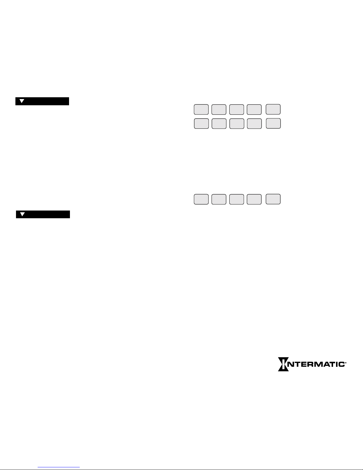
KEYPAD
These keys are used for most data entry. Note dual functions,
numeric or day specific. Using the day group keys WKDY,
WKND and ALL (for all 7 days) greatly speeds the process.
The keypad keys are only functional when the RUN/SET switch is
in the SET position. Pressing keys when in the RUN position will
cause a message to scroll, explaining the function of that key. Press
any key once to stop any of the scrolling error or help messages.
You must press AM or PM after entering time data (except Sunrise
or Sunset) unless in 24-hr. mode. Programming fixed times for
ON and OFF times does not require PULSE, INTVL or ASTRO
keys. Multiple ONs or OFFs can be entered by pressing OK
without programming the alternate OFF or ON. Multiple OFF
times are frequently used to “sweep” off loads which have been
manually switched on after normal occupancy hours.
PULSE and INTVL (Interval) are length-of-time based options.
Maximum Pulse is 127 sec.; minimum is 1 sec. Maximum Interval
is 6 days, 23 hrs., 59 min.; minimum is 1 min. To program Pulses
or Intervals, press the PULSE or INTVL key after entering a Switch
On or Switch Off time; then enter the required duration and press
OK. Note after On Pulses or Intervals have timed out the load
will be Off, and after OFF Pulses or Intervals have timed out the
load will be ON, regardless of the load state prior to the start of
the Pulse or Interval. The INTVL key includes a temporary
override function with a maximum length of 6 days, 23 hrs., 59
min. To program an interval for override, enable a circuit, press
INTVL (without selecting a day), key in the duration and press
OK. Remember INTVL override
is initiated on demand via the
keypad and is not based on a day
AM
PM
PULSE
INTVL
ASTRO
SUN1MON2TUE3WED
4
THU
5
FRI
6
SAT
7
WKDY8WKND
9
ALL
0
Next Generation
SET UP is performed once during
installation to set the internal CLOCK, ASTRO (sunrise/sunset)
times and HOLIDAY references. After entering and okaying the
ASTRO Zone, the timer will display calculated “center of time
zone” times when prompting for sunrise and sunset entries. You
may OK these, enter actual sunrise/sunset times or enter offset
times for early or late ASTRO operation. Sunrise time must be
before noon; sunset time must be after noon. Sunset must not be
within 5 hours of sunrise. Both sunrise and sunset must be
entered, even if only one is used for switching. If neither is
required, you may skip ahead by pressing HLDY or PROG keys.
(See map pp. 26–27 for details.) Holidays are entered with 2-digit
reference numbers; a chart for recording the date(s) is located on
page 21. Leap years are preset through the year 2094.
PROGRAM is used for entering or
changing the switching schedule for loads wired into the time
switch. You can program circuits separately or concurrently. Each
entry affects loads whose Enable switches are in the enable
position at the time of data entry. The time switch is shipped in a
12-hr. AM/PM mode; you can change to 24-hr. by removing a
jumper on the circuit board (see Special Instructions). It can store
a minimum of 400 events, depending on the data type entered.
The time switch prompts you through SET UP and PROGRAM
with LEDs that advance after each entry. There are five important
points to remember:
1)
The RUN/SET
switch must be in the
SET
position to enter,
review or change data.
2) You must press “OK” after each entry, before starting the next.
3) You must press AM or PM after entering time (unless
programming Sunrise and Sunset or in 24-hour mode).
4) When in PROGRAM you must select the loads you want to
control with the Enable switches.
5) RUN/SET switch must be returned to RUN position to enable
automatic control and to save changes to data.
4
5
PROGRAM
SET UP
Page 4

PROG (Program) and SET UP
return you to the beginning of these
categories. Press PROG to select a new day/day group when
programming of a selected day/day group is complete, or to skip
Astro and/or Holiday prompts during SET UP.
REV (Review) allows you to check SET UP or PROGRAM data.
The holidays will review in chronological order regardless of the
order in which they were entered. CLEAR is used during Review
to delete displayed data if changes are required.
The Holiday (HLDY) feature allows the timer to follow special
schedules on selected days or periods of days, based on the date
instead of the usual 7 days of the week. Although Holiday
schedules are normally used to modify or suspend regular weekly
switching activity on actual holidays, the Holiday feature also
allows a variety of special scheduling options that are not satisfied
by the 7-day repeating schedule. See Programming Examples
supplement for details. Each holiday may be one day long or as
many days as necessary. Although each has a reference number
(1–99) that you assign, Holidays occur and review in chronological order, so the order of the reference numbers does not matter.
HLDY (Holiday) allows you to set up or review Holiday data. If a
holiday is a single day, press OK when prompted for the STOP
date, or enter the same date. If you need to switch loads on a holiday, press PROGRAM, press HLDY, enter the reference number
1–99 for that holiday, then press OK. Program the holiday load
schedule just as you would any day or day group. If you do not
program switching times for holidays, the loads will be inactive
during the holiday period; all loads will remain in the state they
were at 11:59 PM on the day preceding the start of the holiday.
You may program Off events at 12:00 AM on holidays to
guarantee loads are off during holidays. Note the STOP date is the
last day the loads will be inactive or under special program
control. The following day the loads will resume normal
scheduling beginning at 12:00 AM. Press PROG to exit the
holiday mode after entering
the last holiday.
7
Next Generation
PROG
REV
SET UP
HLDY
and time, as is normal INTVL. To initiate an override interval, set
the RUN/SET switch to RUN, set the switch for the desired load
to Enable, press the INTVL key and hold, and press the ON/OFF
button for the load you wish to override. The green load indicator
flashes during the interval to show override selection. At the end
of an override interval the load and green LED will turn off,
regardless of the load state before the override or prior programmed schedules. The load will respond to any subsequent program
schedules. An override interval may be ended early only by pushing
the ON/OFF button, or by a power interruption. Thus, a programmed Off event will not end an override interval. The actual
override interval duration is the programmed duration ± 30 sec.,
dependent on the instant in time when the override was initiated.
The Remote Override feature allows a switch contact to initiate an
override interval. The timer detects the closing or opening of
switch contacts wired to the Remote Override Connector (on back
of Logic Module). This allows the remote switch(es) to be maintained (toggle) or normally open or closed momentary (push
button). As with the front panel initiated override interval, the
relevant circuit must have an interval duration programmed, and
its slide switch must be in the Enable position, before an override
interval can be initiated. Any additional remote switch activity
during an override interval will restart the interval. The remote
override may not be used for applications requiring a pulse output,
or to turn loads Off remotely. See Special Instructions for wiring.
ASTRO is pressed (instead of a time entry) after selecting a day
or day group if you want switching to occur at Sunrise and/or
Sunset.
To program ASTRO switching with a Pulse or Interval, press
ASTRO, then PULSE or INTVL, followed by entering a pulse or
interval duration. . .all before OK is pressed.
(Clock adjustment for Daylight Savings Time is automatic; see
Special Instructions for override if DST adjustment is not
required, such as in Arizona, Hawaii and parts of Indiana. The
clock time will be adjusted by 1 hour on the first Sunday of April
and the last Sunday of October at 2:00 AM. Due to unexpected
results, it is recommended you do not attempt programming from
12:00 midnight to 2:00 AM on these two days.)
6
Page 5
Holiday schedules and dates will remain in timer memory until
deliberately cleared. For those Holidays whose dates vary from
year to year, you must manually revise the start and stop dates (in
SET UP review) annually. Holidays may not be programmed to
end before their start date and must end by Dec. 31.
The OK key must be pressed after
each complete entry; pressing it
advances you to the next data prompt. The OK key is similar to
an Enter key. After okaying a switching time, the timer automatically prompts for the alternate switching activity; i.e. Off after
On, On after Off (except after a pulse or interval entry). Pressing
the OK key without making another switching time entry alternates the On/Off prompt, allowing a succession of Off or On
events. OK is the final step after programming all steps and
enabling circuits for each switching time/type.
CLEAR clears the last digit entered; additional digits are cleared
from the display each time CLEAR is pressed. CLEAR is also used
to clear an error code or message and return the display to the
same data that appeared before attempting to OK the data.
While in Review pressing CLEAR deletes the displayed data from
the program for the load(s) selected with Enable. Press REV to
continue Review.
COPY allows you to use the same schedule for groups of days
other than those available on the keypad (WKDYs, WKNDs or
ALL). Simply press COPY after entering a schedule for a specific
day, and at the DAY prompt key in the day you wish to copy to.
You may also copy a day that was previously programmed by
pressing that day’s key, pressing the OK key, then the COPY key.
The display will show the selected day followed by COPY. Now
key in the day you wish to copy to and press OK to confirm.
Select and OK additional copy to
days as required. Four rules
need to be followed when using COPY:
1) You cannot copy to
a day that has already been programmed.
2) You cannot copy from
a day which has already been copied to.
3) You cannot copy to or from
a day group.
OK
CLEAR
COPY
HELP
4) The COPY feature copies the programmed schedules of all the
circuits of the copy from
day to the corresponding circuits of
the copy to
day regardless of the positions of the circuit Enable
switches. Individual circuit schedules may not be copied
independently.
HELP provides help messages specific to each step in SET UP and
PROGRAM. If you make an error, it will be indicated in the LED
display with an error code. (See Error Messages at the back of this
booklet, or press HELP to scroll the message across the display.)
Pressing any key or allowing the message to finish returns the display
to the same point you were at before the error was made.
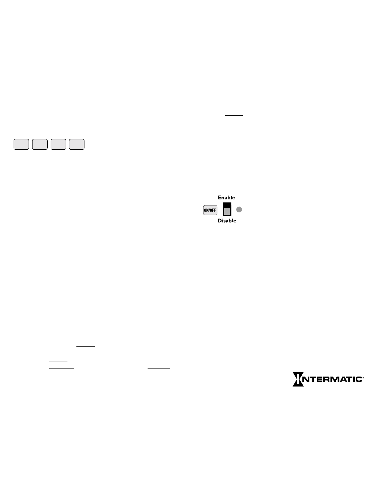
LOAD CONTROLS
There are two controls and an LED indicator for
each load. Enable/Disable activates automatic
switching of the load by the time switch, enables
the override function in RUN mode and selects
circuits being programmed in SET mode.
The ON/OFF key manually switches the load independently of the
time switch and cancels any previously initiated activity, including
PULSEs, INTVLs (Intervals) or override intervals. The ON/OFF key
does not interfere with events that occur after its use. The ON/OFF
keys and LEDs will operate the loads and indicate status regardless of
the position of the RUN/SET switch. When timer power is restored
after a power interruption, all loads will initially be Off. The timer
then restores any enabled loads to their programmed status as of midnight (12:00 AM) of the present day. For this reason, for On periods
that include midnight, if load operation is desired immediately after
power restoration, use a redundant On set point at each affected
midnight (12:00 AM) to guarantee predictable catch-up.
If more than one load is scheduled to turn On, the soft start feature
will turn them On successively at 15 sec. intervals. Therefore, it is
generally advisable to put lighting loads on low-numbered circuits to
hasten their turn-on after power is restored. All same-scheduled loads
turn Off
simultaneously at the scheduled time. If a soft start is not
desired, program those loads using
interval or pulse.
8
Next Generation
9
Page 6

If a soft start other than the factory setting of 15 seconds is desired
press SET UP; and the date will be displayed. Then press
PULSE: SS (for Soft Start) appears in the left two displays with
3 dashes in the rightmost displays. Enter the soft start desired
by keying in a number from 1 to 127 seconds, and then press OK.
This new soft start allows you to lengthen or shorten the
15-second soft start and will affect all available circuits.
INSTRUCTIONS FOR REVIEWING/REVISING DATA
REVIEW PROCEDURE
• Place the Run/Set switch in the Set position to review.
• You must review Clock info (date, time), Astro and
Holiday dates in SET-UP mode.
• You must review all load activity (Fixed times, Astro times, Pulse
operations, Interval operations and special “Holiday” load
activities) in PROGRAM mode.
• In PROGRAM, select only one load at a time using the
ENABLE switch. If more than one circuit is enabled, you will
only see switch activities common to all Enabled circuits.
REVIEW CLOCK, CALENDAR, ASTRO DATA AND
HOLIDAY DATES
To initiate review, press SET-UP (the date is displayed), then press
REV (Review). Continue to press REV for each program you wish to
review. SET-UP stops after the time is displayed if no ASTRO
information has been entered, allowing you to enter Astro data
(Zone, Sunrise and Sunset). If ASTRO information has been entered,
pressing REVafter reviewing the Sunset time will cause the message
“End of Review” to be displayed. Review will then automatically
advance to HOLIDAY, allowing you to select a specific holiday
reference # (01–99) for review. If you want to review all holiday
dates, press REV without selecting a reference number, and the first
reference # will appear. (Not necessarily reference #1 since
holidays review in chronological order beginning Jan. 1). Continue
to press REV to walk through the Ref # and the Start and Stop
dates for each holiday until “End of Review” is displayed. For single
day holidays, Start and Stop dates will be the same. Note Astro
sunrise and sunset times are re-calculated daily by the timer and will
differ from times entered or reviewed on a previous date.
10
REVISE SETUP DATA
To revise or delete displayed information during Setup Review,
simply press CLEAR. When reviewing Astro Sunrise and Sunset
times, you may need to press CLEAR more than one time since
each operation deletes only one digit. You can then immediately
make the revision. Be sure to press OK to enter the new data.
Note that after any revisions to the sunrise Astro time, the sunset
Astro time must be re-entered and okayed. Press REV to continue
the review.
REVIEW PROGRAM
• Be sure to select one load at a time. Failing to do so will allow
you to only review switching activities which are common to all
the circuits selected. In other words, if circuits #1 and circuits #2
are both enabled and are both programmed to come ON at 8:00
A.M., but OFF at different times, the 8:00 A.M. ON time will
be the only set point shown in Review. You must be in the
PROGRAM mode in order to review the programmed load
activities.
• In the PROGRAM mode, you can review switching activities
regardless of whether you programmed them as Fixed Times,
Astro Times, Pulse Switching or Interval Switching. Special
Holiday load activities or interval overrides are also reviewed in
Program.
REVIEW WEEK LONG SWITCHING ACTIVITIES
The normal load switching schedule is a composite of all
applicable individual day schedules, day group schedules and
copied days.The week long review feature allows this composite
schedule to be easily reviewed; by simply pressing the REV key
repeatedly, without first selecting a day, the timer will step thru all
scheduled switching times chronologically, beginning at 12:00
AM Sunday, or by pressing the REV key once, then pressing the
OK key, the timer will automatically step thru each scheduled
switching time, displaying each time for about 2 seconds. Press the
OK key to pause auto review. Press the OK key again to resume
auto review; or press the rev key to continue review manually.
The scheduled switching times may only be reviewed, not cleared
during week long review. Follow the steps below for individual
day/day group review if any scheduled events need to be cleared.
11
Page 7

reviewing Monday only would immediately give the "End of
Review"message, indicating no activity, yet there will be activity
on Monday due to the weekday (8) day group schedule.
Therefore, always use the week long review feature for final
verification of the complete schedule.
NOTE: The effect of Holiday schedules cannot be seen during
week long review, so in addition to week long review, all Holidays
should also be reviewed to accurately predict the timer's operation.
REVIEW SPECIAL HOLIDAY SWITCHING
ACTIVITIES
To review special holiday switching activities, press PROG then
HLDY. Next enter the holiday reference number (01 to 99) for
the holiday activities you wish to review. Press OK, then press
REV, at which point the colon will disappear from the display.
Press REV again to display the first switching activity. Continue
to press REV while observing the LED prompts and program
times and/or Pulse and Interval times until “End of Review” is
displayed. Automatic review can also be used by pressing PROG,
HLDY, then entering the Holiday reference #, OK, REV, then
OK. If desired, use OK key to pause and resume auto review.
REVIEW INTERVAL OVERRIDE OPERATION
• Press PROG and do not select a day or day group.
• Press INTVL. The interval duration in days, hours and minutes
as programmed will be displayed.
• When reviewing data, the appropriate ENABLE switch must be
used, one switch at a time.
REVISE PROGRAM DATA
When revising program data, make note of the following:
• Run/Set switch must be in Set position
• Data is revised by causing it to be displayed during Review,
deleting it with the CLEAR key, and then replacing it with
new data, if desired.
• Program data may not be revised during week long review. You
must revise the data by reviewing the appropriate individual day,
day group, or "copied
from" day.
13
Next Generation
REVIEW INDIVIDUAL DAY, DAY GROUP, OR
COPIED ACTIVITIES
• Press PROG, then press the day key (SUN/1 through SAT/7) or
the day group key (wkDY/8, wkND/9 or ALL/0) to select the
day or day group to review.
NOTE: If you have entered data as a day group and attempt to
review any of the days individually, the message “End of Review”
will be displayed. This is because you must review data just as it
was entered, in this example, as a day group.
• Press REV, at which point the colon will disappear. Press REV
again to review the first programmed switch time. The associated
Switch On or Switch Off LED will be lit.
• Press REV again to review the next activity. If a switching time
includes a pulse or interval when you press REV, the length of
the pulse or interval will be displayed and the LED for Pulse or
INTVL will be lit. Continue to press REV until “End of
Review” is displayed. The display now prompts for a new day or
day group selection. Repeat the steps above for each circuit
individually.
• To automatically review a day or day group, press PROG, select
a day (SUN/1 thru SAT/7) or day group (wkDY/8, wkND/9 or
ALL/0), press REV, then press OK. If desired, press OK again to
pause auto review; press OK again to resume review, or press
REV to continue reviewing manually.
• If a day was copied from
, you may review all days it was copied
to by selecting the copy from day, pressing OK, pressing COPY,
then pressing REV. For example, display might show 1 COPY
2 meaning that the day 1 schedule has been copied to day 2.
Push REV more times to review additional copy to
days. If a day
is a copy, you may determine the day it was copied from by
selecting the day then pressing REV twice. A message will scroll
indicating the day it was copied from.
• Individual day review is not recommended for verifying
predicted operation of the timer because, since the actual
schedule is the composite of days, day groups, and copied days,
all of these would need to be reviewed, then manually combined,
to know the actual schedule for a given day. For example, if the
weekday (8) day group has scheduled activity, but no individual
weekdays (Monday thru Friday) have scheduled activity,
12
Page 8

• During automatic review, the OK key must be used to pause
the display before the displayed data can be deleted.
• After any program data is cleared, review is terminated. The
timer is now in the program mode for the selected day,
anticipating a new entry. You may make the new entry, restart
review, or return to Run position.
• It is recommended that you repeat the "week long review" after
any revisions are complete to verify that all revisions were
implemented as desired.
To revise or delete displayed information during Program Review,
simply press CLEAR. You can then immediately make the revision
desired. Be sure to press OK to enter the new data. Press REV to
restart the review. Note that you can delete a Pulse or Interval
option from any Switch On or Switch Off time by pressing
CLEAR when the time is displayed during Review. You must reenter, then OK the Switch On or Switch Off time, even if it has
not changed. Likewise, you may add a Pulse or Interval to a
Switch On or Switch Off time by pressing CLEAR when the time
is displayed. You must re-enter the time, press PULSE or INTVL,
enter the length of Pulse or Interval, then press OK.
Programming Example (2 circuits only)
Be sure RUN/SET switch is in SET position. At the initial
installation and/or to clear out all previously programmed data,
press and hold the CLEAR button, then press and release RESET
and continue to hold the
CLEAR button until RESET appears in
the display. Note leading zeros are not required for the left-most
prompted digit.
Press SET UP (unless prompt is flashing at Day of Wk/Time)
Assume • Current date is January 21, 1997
• Current time is 2:30 PM
• Location is Des Moines, Iowa (Zone 5 from Astro
Zone Map and center of Central time zone)
• The building owner wants the lights Off 30 min.
after sunrise and On 30 min. prior to sunset.
• Two Holiday or special schedules – July 4th and a
2-week office closing 12/22/97 thru 1/5/98
Press TUE/3, OK (selects day); 2, 3, 0, PM, OK (selects time);
1, 2, 1, 9, 7, OK (selects date); 5, OK (selects zone).
14
The time switch now displays the calculated center of
time zone sunrise time of -7:33 AM. Since the building
owner wants to offset actual sunrise time by having lights
switch off 30 min. late, press CLEAR, CLEAR, CLEAR
(deletes automatic center of zone calculation; display
now shows --:--) and 8, 0, 3, OK (selects new offset
sunrise time). The time switch now displays the
calculated center of time zone sunset time of -5:13 PM.
Since the building owner wants to offset actual sunset
time, press CLEAR, CLEAR, CLEAR (deletes automatic
center of zone calculation; display now shows --:--);
4, 4, 3, OK (selects new offset sunset time);
1, OK (selects first
Holiday schedule Ref. # for 1997);
7, 0, 4, OK, OK (pressing OK twice selects same start
and stop date);
2, OK (selects second
Holiday schedule Ref. #);
1, 2, 2, 2, OK (start date); 1, 2, 3, 1 OK (stop date);
3, OK (selects first
Holiday schedule Ref. # for 1998);
1, 0, 1, OK (start date) and 1, 0, 5, OK (stop date).
SET UP is now complete.
Press PROG (to enter
PROGRAM
mode and exit
SET UP
)
Assume • Programming for two loads:
#1 indoor lighting, #2 buzzer
• Load 1 switches On 7:50 AM to 4:40 PM Monday
thru Friday and 7:50 AM to 12:00 PM noon Sat. only.
• Load 2 operates the signal twice daily for 15 sec. at
8:00 AM and 4:30 PM Monday thru Friday only.
Set Load slide switches to Enable Load 1 and Disable 2
Press WKdy/8, OK (selects weekdays only); 7, 5, 0, AM, OK
(load On time); 4, 4, 0, PM, OK (load Off time)
Set Load slide switches to Disable Load 1 and Enable 2
Press 8, 0, 0, AM, PULSE, 1, 5, OK (selects 15 sec. load On
at 8:00 AM); 4, 3, 0, PM, PULSE, 1, 5, OK (selects 15
sec. load On at 4:30 PM)
Press PROG to select a new day or day group to program.
15
Next Generation
Page 9

SWITCHING TIMES
Day/Day
CIRCUITS SWITCH ON SWITCH OFF PULSE INTVL ASTRO
Group
1 2 3 4
Override
AM
PM
:
:
N
O
T
I
M
E
E
N
T
R
Y
R
E
Q
U
I
R
E
D
Sec
:
AM
PM
/
AM
PM
:
:
Sec
:
AM
PM
/
AM
PM
:
:
Sec
:
AM
PM
/
AM
PM
:
:
Sec
:
AM
PM
/
AM
PM
:
:
Sec
:
AM
PM
/
AM
PM
:
:
Sec
:
AM
PM
/
AM
PM
:
:
Sec
:
AM
PM
/
AM
PM
:
:
Sec
:
AM
PM
/
AM
PM
:
:
Sec
:
AM
PM
/
AM
PM
:
:
Sec
:
AM
PM
/
AM
PM
:
:
Sec
:
AM
PM
/
AM
PM
:
:
Sec
:
AM
PM
/
AM
PM
:
:
Sec
:
AM
PM
/
AM
PM
:
:
Sec
:
AM
PM
/
AM
PM
:
:
Sec
:
AM
PM
/
AM
PM
:
:
Sec
:
AM
PM
/
AM
PM
:
:
Sec
:
AM
PM
/
AM
PM
:
:
Sec
:
AM
PM
/
AM
PM
:
:
Sec
:
AM
PM
/
AM
PM
:
:
Sec
:
AM
PM
/
AM
PM
:
:
Sec
:
AM
PM
/
AM
PM
:
:
Sec
:
AM
PM
/
AM
PM
:
:
Sec
:
AM
PM
/
AM
PM
:
:
Sec
:
AM
PM
/
AM
PM
:
:
Sec
:
AM
PM
/
AM
PM
:
:
Sec
:
AM
PM
/
Set Load slide switches to Enable Load 1and Disable 2
Press SAT/7, OK (selects Saturday only); 7, 5, 0, AM, OK
(load On time); 1, 2, 0, 0, PM, OK (load Off time)
Scheduled PROGRAM is now complete.
Assume A 30 min. INTERVAL override duration is desired for
Load 1.
Set Load slide switches to Enable Load 1 and Disable 2
Press PROG (completes programming for Saturday data)
INTVL, 3, 0, OK (sets user selectable interval duration
to 30 minutes)
(Note a day or day group is not selected
since Interval
override is selected on demand
by the building occupants.)
Interval override duration selection is now complete.
The interval override will not begin until called for by
the user via the front panel pushbuttons, or by a switch
connected to the remote override connector.
To complete programming, download all data into non-volatile
memory by sliding the SET/RUN switch to RUN. Note SAVE is
displayed momentarily and the current day of week and time
appear in the display.
BATTERY B ACKUP
All programmed data is protected by non-volatile memory and can
only be changed or deleted by reprogramming, regardless of power
outage durations. A factory installed 8-year lithium battery backup
maintains accurate time and calendar information. See Special
Instructions for replacement.
16
17
Next Generation
Page 10

18
SWITCHING TIMES
Day/Day
CIRCUITS SWITCH ON SWITCH OFF PULSE INTVL ASTRO
Group
5 6 7 8
Override
AM
PM
:
:
N
O
T
I
M
E
E
N
T
R
Y
R
E
Q
U
I
R
E
D
Sec
:
AM
PM
/
AM
PM
:
:
Sec
:
AM
PM
/
AM
PM
:
:
Sec
:
AM
PM
/
AM
PM
:
:
Sec
:
AM
PM
/
AM
PM
:
:
Sec
:
AM
PM
/
AM
PM
:
:
Sec
:
AM
PM
/
AM
PM
:
:
Sec
:
AM
PM
/
AM
PM
:
:
Sec
:
AM
PM
/
AM
PM
:
:
Sec
:
AM
PM
/
AM
PM
:
:
Sec
:
AM
PM
/
AM
PM
:
:
Sec
:
AM
PM
/
AM
PM
:
:
Sec
:
AM
PM
/
AM
PM
:
:
Sec
:
AM
PM
/
AM
PM
:
:
Sec
:
AM
PM
/
AM
PM
:
:
Sec
:
AM
PM
/
AM
PM
:
:
Sec
:
AM
PM
/
AM
PM
:
:
Sec
:
AM
PM
/
AM
PM
:
:
Sec
:
AM
PM
/
AM
PM
:
:
Sec
:
AM
PM
/
AM
PM
:
:
Sec
:
AM
PM
/
AM
PM
:
:
Sec
:
AM
PM
/
AM
PM
:
:
Sec
:
AM
PM
/
AM
PM
:
:
Sec
:
AM
PM
/
AM
PM
:
:
Sec
:
AM
PM
/
AM
PM
:
:
Sec
:
AM
PM
/
AM
PM
:
:
Sec
:
AM
PM
/
SWITCHING TIMES
Day/Day
CIRCUITS SWITCH ON SWITCH OFF PULSE INTVL ASTRO
Group910 11 12
Override
AM
PM
:
:
N
O
T
I
M
E
E
N
T
R
Y
R
E
Q
U
I
R
E
D
Sec
:
AM
PM
/
AM
PM
:
:
Sec
:
AM
PM
/
AM
PM
:
:
Sec
:
AM
PM
/
AM
PM
:
:
Sec
:
AM
PM
/
AM
PM
:
:
Sec
:
AM
PM
/
AM
PM
:
:
Sec
:
AM
PM
/
AM
PM
:
:
Sec
:
AM
PM
/
AM
PM
:
:
Sec
:
AM
PM
/
AM
PM
:
:
Sec
:
AM
PM
/
AM
PM
:
:
Sec
:
AM
PM
/
AM
PM
:
:
Sec
:
AM
PM
/
AM
PM
:
:
Sec
:
AM
PM
/
AM
PM
:
:
Sec
:
AM
PM
/
AM
PM
:
:
Sec
:
AM
PM
/
AM
PM
:
:
Sec
:
AM
PM
/
AM
PM
:
:
Sec
:
AM
PM
/
AM
PM
:
:
Sec
:
AM
PM
/
AM
PM
:
:
Sec
:
AM
PM
/
AM
PM
:
:
Sec
:
AM
PM
/
AM
PM
:
:
Sec
:
AM
PM
/
AM
PM
:
:
Sec
:
AM
PM
/
AM
PM
:
:
Sec
:
AM
PM
/
AM
PM
:
:
Sec
:
AM
PM
/
AM
PM
:
:
Sec
:
AM
PM
/
AM
PM
:
:
Sec
:
AM
PM
/
AM
PM
:
:
Sec
:
AM
PM
/
19
Next Generation
Page 11

20
SWITCHING TIMES
Day/Day
CIRCUITS SWITCH ON SWITCH OFF PULSE INTVL ASTRO
Group1314 15 16
Override
AM
PM
:
:
N
O
T
I
M
E
E
N
T
R
Y
R
E
Q
U
I
R
E
D
Sec
:
AM
PM
/
AM
PM
:
:
Sec
:
AM
PM
/
AM
PM
:
:
Sec
:
AM
PM
/
AM
PM
:
:
Sec
:
AM
PM
/
AM
PM
:
:
Sec
:
AM
PM
/
AM
PM
:
:
Sec
:
AM
PM
/
AM
PM
:
:
Sec
:
AM
PM
/
AM
PM
:
:
Sec
:
AM
PM
/
AM
PM
:
:
Sec
:
AM
PM
/
AM
PM
:
:
Sec
:
AM
PM
/
AM
PM
:
:
Sec
:
AM
PM
/
AM
PM
:
:
Sec
:
AM
PM
/
AM
PM
:
:
Sec
:
AM
PM
/
AM
PM
:
:
Sec
:
AM
PM
/
AM
PM
:
:
Sec
:
AM
PM
/
AM
PM
:
:
Sec
:
AM
PM
/
AM
PM
:
:
Sec
:
AM
PM
/
AM
PM
:
:
Sec
:
AM
PM
/
AM
PM
:
:
Sec
:
AM
PM
/
AM
PM
:
:
Sec
:
AM
PM
/
AM
PM
:
:
Sec
:
AM
PM
/
AM
PM
:
:
Sec
:
AM
PM
/
AM
PM
:
:
Sec
:
AM
PM
/
AM
PM
:
:
Sec
:
AM
PM
/
AM
PM
:
:
Sec
:
AM
PM
/
AM
PM
:
:
Sec
:
AM
PM
/
HOLIDAY REFERENCE # (Up to 99 holidays or holiday durations can be programmed)
01 / /
02 / /
03 / /
04 / /
05 / /
06 / /
07 / /
08 / /
09 / /
10 / /
11 / /
12 / /
13 / /
14 / /
15 / /
16 / /
17 / /
18 / /
19 / /
20 / /
21 / /
22 / /
23 / /
24 / /
25 / /
26 / /
27 / /
28 / /
HOLIDAY START END
Month/Date Month/Date
21
Next Generation
Page 12

HOLIDAY SWITCHING TIMES
HOLIDAY CIRCUITS SWITCH ON SWITCH OFF PULSE INTVL ASTRO
Ref #
5 6 7 8
Override
AM
PM
:
:
N
O
T
I
M
E
E
N
T
R
Y
R
E
Q
U
I
R
E
D
Sec
:
AM
PM
/
AM
PM
:
:
Sec
:
AM
PM
/
AM
PM
:
:
Sec
:
AM
PM
/
AM
PM
:
:
Sec
:
AM
PM
/
AM
PM
:
:
Sec
:
AM
PM
/
AM
PM
:
:
Sec
:
AM
PM
/
AM
PM
:
:
Sec
:
AM
PM
/
AM
PM
:
:
Sec
:
AM
PM
/
AM
PM
:
:
Sec
:
AM
PM
/
AM
PM
:
:
Sec
:
AM
PM
/
AM
PM
:
:
Sec
:
AM
PM
/
AM
PM
:
:
Sec
:
AM
PM
/
AM
PM
:
:
Sec
:
AM
PM
/
AM
PM
:
:
Sec
:
AM
PM
/
AM
PM
:
:
Sec
:
AM
PM
/
AM
PM
:
:
Sec
:
AM
PM
/
AM
PM
:
:
Sec
:
AM
PM
/
AM
PM
:
:
Sec
:
AM
PM
/
AM
PM
:
:
Sec
:
AM
PM
/
AM
PM
:
:
Sec
:
AM
PM
/
AM
PM
:
:
Sec
:
AM
PM
/
AM
PM
:
:
Sec
:
AM
PM
/
AM
PM
:
:
Sec
:
AM
PM
/
AM
PM
:
:
Sec
:
AM
PM
/
AM
PM
:
:
Sec
:
AM
PM
/
AM
PM
:
:
Sec
:
AM
PM
/
22
HOLIDAY SWITCHING TIMES
HOLIDAY CIRCUITS SWITCH ON SWITCH OFF PULSE INTVL ASTRO
Ref #
1 2 3 4
Override
AM
PM
:
:
N
O
T
I
M
E
E
N
T
R
Y
R
E
Q
U
I
R
E
D
Sec
:
AM
PM
/
AM
PM
:
:
Sec
:
AM
PM
/
AM
PM
:
:
Sec
:
AM
PM
/
AM
PM
:
:
Sec
:
AM
PM
/
AM
PM
:
:
Sec
:
AM
PM
/
AM
PM
:
:
Sec
:
AM
PM
/
AM
PM
:
:
Sec
:
AM
PM
/
AM
PM
:
:
Sec
:
AM
PM
/
AM
PM
:
:
Sec
:
AM
PM
/
AM
PM
:
:
Sec
:
AM
PM
/
AM
PM
:
:
Sec
:
AM
PM
/
AM
PM
:
:
Sec
:
AM
PM
/
AM
PM
:
:
Sec
:
AM
PM
/
AM
PM
:
:
Sec
:
AM
PM
/
AM
PM
:
:
Sec
:
AM
PM
/
AM
PM
:
:
Sec
:
AM
PM
/
AM
PM
:
:
Sec
:
AM
PM
/
AM
PM
:
:
Sec
:
AM
PM
/
AM
PM
:
:
Sec
:
AM
PM
/
AM
PM
:
:
Sec
:
AM
PM
/
AM
PM
:
:
Sec
:
AM
PM
/
AM
PM
:
:
Sec
:
AM
PM
/
AM
PM
:
:
Sec
:
AM
PM
/
AM
PM
:
:
Sec
:
AM
PM
/
AM
PM
:
:
Sec
:
AM
PM
/
AM
PM
:
:
Sec
:
AM
PM
/
NOTE: Holidays not programmed for switching times will automatically skip
all load activities normally associated with the day(s) that the holiday(s) occur.
23
Next Generation
Page 13

24
HOLIDAY SWITCHING TIMES
HOLIDAY CIRCUITS SWITCH ON SWITCH OFF PULSE INTVL ASTRO
Ref #
9 10 11 12
Override
AM
PM
:
:
N
O
T
I
M
E
E
N
T
R
Y
R
E
Q
U
I
R
E
D
Sec
:
AM
PM
/
AM
PM
:
:
Sec
:
AM
PM
/
AM
PM
:
:
Sec
:
AM
PM
/
AM
PM
:
:
Sec
:
AM
PM
/
AM
PM
:
:
Sec
:
AM
PM
/
AM
PM
:
:
Sec
:
AM
PM
/
AM
PM
:
:
Sec
:
AM
PM
/
AM
PM
:
:
Sec
:
AM
PM
/
AM
PM
:
:
Sec
:
AM
PM
/
AM
PM
:
:
Sec
:
AM
PM
/
AM
PM
:
:
Sec
:
AM
PM
/
AM
PM
:
:
Sec
:
AM
PM
/
AM
PM
:
:
Sec
:
AM
PM
/
AM
PM
:
:
Sec
:
AM
PM
/
AM
PM
:
:
Sec
:
AM
PM
/
AM
PM
:
:
Sec
:
AM
PM
/
AM
PM
:
:
Sec
:
AM
PM
/
AM
PM
:
:
Sec
:
AM
PM
/
AM
PM
:
:
Sec
:
AM
PM
/
AM
PM
:
:
Sec
:
AM
PM
/
AM
PM
:
:
Sec
:
AM
PM
/
AM
PM
:
:
Sec
:
AM
PM
/
AM
PM
:
:
Sec
:
AM
PM
/
AM
PM
:
:
Sec
:
AM
PM
/
AM
PM
:
:
Sec
:
AM
PM
/
AM
PM
:
:
Sec
:
AM
PM
/
HOLIDAY SWITCHING TIMES
HOLIDAY CIRCUITS SWITCH ON SWITCH OFF PULSE INTVL ASTRO
Ref #
13
14 15 16
Override
AM
PM
:
:
N
O
T
I
M
E
E
N
T
R
Y
R
E
Q
U
I
R
E
D
Sec
:
AM
PM
/
AM
PM
:
:
Sec
:
AM
PM
/
AM
PM
:
:
Sec
:
AM
PM
/
AM
PM
:
:
Sec
:
AM
PM
/
AM
PM
:
:
Sec
:
AM
PM
/
AM
PM
:
:
Sec
:
AM
PM
/
AM
PM
:
:
Sec
:
AM
PM
/
AM
PM
:
:
Sec
:
AM
PM
/
AM
PM
:
:
Sec
:
AM
PM
/
AM
PM
:
:
Sec
:
AM
PM
/
AM
PM
:
:
Sec
:
AM
PM
/
AM
PM
:
:
Sec
:
AM
PM
/
AM
PM
:
:
Sec
:
AM
PM
/
AM
PM
:
:
Sec
:
AM
PM
/
AM
PM
:
:
Sec
:
AM
PM
/
AM
PM
:
:
Sec
:
AM
PM
/
AM
PM
:
:
Sec
:
AM
PM
/
AM
PM
:
:
Sec
:
AM
PM
/
AM
PM
:
:
Sec
:
AM
PM
/
AM
PM
:
:
Sec
:
AM
PM
/
AM
PM
:
:
Sec
:
AM
PM
/
AM
PM
:
:
Sec
:
AM
PM
/
AM
PM
:
:
Sec
:
AM
PM
/
AM
PM
:
:
Sec
:
AM
PM
/
AM
PM
:
:
Sec
:
AM
PM
/
AM
PM
:
:
Sec
:
AM
PM
/
25
Next Generation
Page 14

27
SUNRISE SUNSET
Detroit +20 +20
El Paso -5 -5
Houston +10 +10
Honolulu +20 +20
Las Vegas -30 -30
Los Angeles -20 -20
Miami +10 +10
New York -15 -15
Oklahoma City +20 +20
Philadelphia -10 -10
SUNRISE SUNSET
Phoenix +15 +15
Pittsburgh +10 +10
Portland, OR 0 0
Richmond, VA 0 0
San Diego -25 -25
San Francisco 0 0
Seattle -5 -5
Tampa +20 +20
You may also check the local
newspaper for actual local times.
26
After the astro zone is entered the
approximate sunrise and sunset times
for the center of the time zone will be
displayed. Depending on your location
relative to the center, you may want to
change (offset) this time. Following are
approximate offsets (plus or minus) for
selected cities in 5 minute increments.
SUNRISE SUNSET
Albuquerque -5 -5
Atlanta +25 +25
Baltimore -5 -5
Bangor, ME -35 -35
Boston -30 -30
Chicago -20 -20
Cleveland +15 +15
Dallas +15 +15
Denver -10 -10
Des Moines 0 0
TIME ZONES
Page 15

SPECIAL INSTRUCTIONS
Opening the Logic Module To remove the metal logic
module cover, remove the screws on the back and lift off,
exposing the circuit board. Reverse steps to replace cover. The
following three procedures require cover removal.
Converting to 24 Hour Display Mode The time switch is
shipped with 12 hr. AM/PM timekeeping; 24 hr. is available by
removing the jumper from the pin connector on the circuit
board. The jumper(s) may be stored for later use by reinstalling
on the outer pins only.
Daylight Saving Time
Override Override the
automatic DST adjustment
(in Arizona, Hawaii and
parts of Indiana) by
removing the jumper
on the circuit board.
Battery Replacement
The 8 yr. battery is located on the back of the circuit board under
the metal battery terminal clips. Replace with Panasonic or
Rayovac BR2325 (or equivalent).
Load Control Wiring With the logic module removed you
have access to the load control relays. Note all relays are identified
with circuit numbers 1–8 or 1–16. Each relay is also identified
with relay ladder diagrams for the common (COM), normally
open (N.O.) and normally closed (N.C.) connections.
NOTE: Contacts are isolated to enable switching loads of a
voltage different than the timer power voltage. You may need to
connect power to the common (COM) terminals. Add jumpers
as required. Do not mix solid and stranded wires under the
same terminal.
29
Next Generation
SPECIAL INSTRUCTIONS
Enclosure Mounting
Follow the instructions
included with the 2
mounting brackets. They
have several holes (3 are
slotted) for securing the
enclosure. Mount using
suitable hardware. For ease
of installation the cover can
be removed by lifting
upward off the hinges.
WARNING: Disconnect all power at the service panel before
removing the logic module.
Removing Logic Module (required for wiring). Remove the 4
Philips Head screws and set them aside for reinstallation. Using a
flat-bladed screwdriver in the slot at the top of the logic module,
gently pull it away from the enclosure.
STOP: Disconnect cable from rear of logic module by pulling
straight back on the connector pull tab.
Changing Power Input Voltage–Multi-volt Models
ET70815CR and ET71615CR
These models can be
powered by any industry
standard 50–60Hz AC
voltage, 120 to 277 V. To
change from the 120VAC
factory setting, locate the
voltage selector jumper and
insert over the pair marked
with the desired voltage
(208, 240, or 277 VAC).
Slot for removal
28
24 HOUR MODE
DST OVERRIDE
BATTERY REPLACEMENT
Page 16

30
NOTE: To enable switching loads of a voltage different than the timer
power voltage, the outputs from this timer are isolated relay contacts. You
need to connect a source of power to the common (COM) terminals as
shown above. Do not mix solid and stranded wires under the same
terminal.
SPECIAL INSTRUCTIONS
Remote Override To obtain access to the
remote override connector for circuits 1–4,
remove the two screws as shown from the
connector insulator. Then loosen the
remaining screw 1/2 turn and pivot the
insulator to the left, out of the way of
the remote override
connector. Route wiring and
insulating tube around the
control relays. The supplied
insulating tube must be
used if customer-supplied
field wiring does not have
300 volt or greater rated
insulation (such as bell
or thermostat wire).
The tubing must extend
into the connector insulator
and must extend beyond the
enclosure wall (typically into
the conduit).
NOTE: If your application requires more than 4 circuits of
remote override, order Intermatic accessory #156ET9402A for
8 circuits of override or #156ET9403A for 16 circuits of override.
Re-installing Logic Module Carefully plug the cable
connector straight into the connector on the rear of the logic
module. The shape on both connectors must line up to allow the
cable connector to be seated. Locate the logic module panel in the
housing by using the tabs (2 or 3) located at the bottom of the
logic module plate. Locate these tabs in the slotted holes provided
in the enclosure. Tilt the top of the logic module back into
position and secure with the 4 screws provided.
REMOTE OVERRIDE
31
Next Generation
TYPICAL WIRING CONFIGURATION
Multi-volt Models (ET70815CR shown)
WARNING: If timer power supply voltage is 208/240/277V,
you must move the input voltage selector jumper on the power
board. See Special Instructions. 24V models do not have this
jumper; connect 24VAC 60 Hz only to 24V timer power terminals.
Page 17

TROUBLESHOOTING
Problem Solution(s)
Display Does • Make sure flat cable is properly plugged into the
Not Light rear of the logic module. Refer to “Re-installing
logic module” in Special Instructions. If connector will not install easily, check for bent pins.
• On multi-volt models make sure the voltage
selector jumper is correctly installed and that
matching voltage is present at timer power
terminals. On 24V models make sure 24VAC
is present at timer power terminals.
Loads Not • Check wiring. Note the load contacts are
Switching isolated to allow you to switch loads with a
voltage different than the timer power. You may
have forgotten to add the appropriate connections required to power the load contacts. See
wiring examples.
• Check to ensure all breakers or disconnects
have been reset.
• Make sure load switches are in Enable position
for automatic switching.
• After a power interruption all loads will be Off
and will “catch up” to the present programmed
state as of midnight of the present day.
Schedules that turn On one day, then Off one
or more days later, need a redundant switch On
time at 12:00 AM. See “Load Controls” for
details.
• Make sure the SET/RUN switch is set to RUN.
• Note that override intervals are not ended by
scheduled Off events. Override intervals may
only be ended by timing out, a power interruption, or by pressing the ON/OFF key.
• Review SETUP to see if timer could be following
a holiday program with no scheduled activity.
Next Generation
33
TYPICAL WIRING CONFIGURATION
24 Volt Models
(ET70815CR24 shown)
32
WARNING: Connect 24 VAC 60 Hz only to 24V timer power
terminals.
NOTE: To enable switching loads of a voltage different than the timer
power voltage, the outputs from this timer are isolated relay contacts. You
need to connect a source of power to the common (COM) terminals as
shown above. Do not mix solid and stranded wires under the same
terminal.
Page 18

Problem Solution(s)
Difficulty in • The two most common mistakes are forgetting
Programming to press AM or PM after each time entry and
forgetting to select a load with the Enable
switch. You cannot program switch times
(PROGRAM) unless you select a load using the
Enable switches. Pressing the HELP key
when an error (ERR--) message appears will
explain the error and may offer
recommended action.
Interval • An interval duration needs to have been
Override previously programmed (check by pressing
Won’t Start INTVL key in SET UP mode) and the circuit
must be Enabled.
Interval • The remote switch only starts the interval
Override Won’t override. Operating it again restarts the
Stop with interval.
Remote Switch
Interval • Actual duration is the programmed duration ±
Override 30 seconds.
Duration Varies
Switch On/ • After any Pulse or Interval entry, the Switch
Off Display On or Switch Off LED does not alternate,
Doesn’t since most Pulse or Interval applications
Alternate require only On or Off. Press OK without a
During time entry to alternate the Switch On/Off
Programming display if required.
Some • All review should be done with only one circuit
Switching enabled at a time. If more than one is enabled,
Times Don’t only events common to the circuits selected
Show During will show during review. To see all possible
Review scheduled events, the week long review should
be used.
Next Generation
35
34
Problem Solution(s)
Load Switches • Using the REV function, check program times
at Incorrect against the times you entered in the chart.
Time • Review SETUP to see if the timer is following
a holiday schedule. Holiday dates and schedules from the prior year do not automatically
clear or adjust. They must be manually revised
or removed annually.
• When using pulse or interval “On” programming, the load will switch On at the scheduled
time and Off at that time, plus the pulse or
interval duration. For “Off” pulses or intervals
the load will switch Off at the scheduled time,
and On at that time plus the pulse or interval
duration, even if the load was not On before
the start of the “Off” pulse or interval.
• This timer provides an automatic 15 sec. delay
between successive circuits when programmed
to switch at the same On time. Use the Interval or Pulse features to eliminate if required.
Note: ASTRO switching times change daily
according to changing Sunrise and Sunset
Consider fixed times with this in mind, e.g. a
fixed Off intended to end an Astro On would
be ignored if sunset moves beyond the fixed
Off time. The fixed event should be scheduled
to occur outside the range of the Astro event,
or an Astro Pulse should be considered.
Note: Override intervals are not ended by
scheduled events; they can only be ended by
timing out, power interruptions, or by pressing
the ON/OFF key.
Timer Ignores • Processor is “locked up”. Press and release
Pushbuttons RESET button while holding down the
CLEAR button. Release CLEAR when “reset”
appears in display. If no improvement, remove
and restore AC power and battery, then re-try.
Page 19

ERR 04 Clock time not setup
ERR 05 Clock date not setup
ERR 06 ASTRO not setup
ERR 07 HOLIDAY not setup
ERR 08 OVERRIDE not setup
ERR 09 ASTRO entry not applicable
ERR 10 COPY key not applicable
ERR 11 Unable to clear a set point in week long review mode –
set points may only be cleared from an individual
day’s program
ERR 12 Internal calculation error – may not be recoverable –
reset the time switch
ERR 13 Day groups may not be copied to or from
ERR 14 No ON or OFF time entry is allowed when entering an
Astro Set Point
ERR 15 A day may not be copied to itself or to a day which has
already been programmed.
ERR 16 February 29th is only permitted in leap year
ERR 17 No circuit selected–select a circuit using the circuit
enable switches
ERR 18 Astro entry is out of limits–SUNRISE must be before
noon and SUNSET must be after noon. SUNSET must
not be within 5 hours of SUNRISE.
ERR 19 The date does not agree with the previously entered
day of the week–review and correct one of the entries.
ERR 20 Holidays may not end before they start and they must
end by Dec. 31.
ERR 21 The selected holiday has already been used–Press
REVIEW to see its definition.
ERR 22 HOLIDAY PROGRAM must be cleared before
clearing holiday number.
ERR 23 Copied to days may be cleared but may not be copied
or changed.
ERR 0A HOLIDAY entry not applicable
ERR 0b Override entry not applicable
ERR 0C PULSE entry not applicable
ERR 0d INTERVAL entry not applicable
36
Problem Solution(s)
Events programmed via Day Group
or Copy Day methods will not show when
reviewing individual days or vice versa.
Difficulty in • When using pulsed output for switching a
Programming/ latching relay or contactor without “self-
Reviewing On/ clearing” contacts, one circuit is dedicated to
Off Latching the load Turn On Pulse and another to the
Pulse Turn Off Pulse. The pulses are created by
or turning the respective circuits On
momentarily
Output to (1 to 2 sec.). Therefore all events must be
Latching programmed and will review as On
Pulses.
Contactor The On
time(s) of the controlled load will be
Remains On shown as On
Pulses for one circuit and the Off
After an Off time(s) will review as On Pulses for the other
Pulse circuit. Note: Using the manual On/Off keys to
switch this type of contactor On or Off will not
provide the expected result and may cause
damage to the contactor coil. For this application
an external Momentary Pushbutton must be
added for both circuits. Refer to the
Programming Examples booklet for more
information.
NOTE: If you need more programming assistance, request form
#158ET9311, Programming Examples, which contains step-bystep instructions for several complex programs.
ERROR MESSAGES
Pressing HELP when an error code is displayed will cause an error
message and recommended action to scroll on display. Press any
key to stop message and restore pre-error display.
ERR 01 Too many keys pressed or HELP key not pressed first
ERR 02 Numeric entry not applicable
ERR 03 AM - PM key entry not applicable
Next Generation
37
Page 20

ERR 0E Invalid or incomplete entry
ERR 0F Unrecognized key
ERR 1A No AM or PM selection
ERR 1b Review entry not applicable
ERR 1C One or more of the selected circuits has a program
conflict
ERR 1d The day of the week entry does not agree with the
previously entered date–the date has been cleared and
you must re-enter both
ERR I E Out of memory
ERR I F Holidays may not overlap - Press REVIEW to identify
the conflict.
NOTE: Error messages are subject to change with later software
revisions.
38
 Loading...