

Page 1

TruVision IP PTZ
Camera Installation
Guide
P/N 1072666A-EN • REV 1.0 • ISS 24SEP13
Page 2
Copyright © 2013 UTC Fire & Security Americas Corporation, Inc.
Interlogix is part of UTC Climate Controls & Security, a unit of United Technologies Corporation.
Trademarks and
Manufacturer UTC Fire & Security Americas Corporation, Inc.
Certification
FCC compliance Class A: This equipment has been tested and found to comply with the limits for a Class A
ACMA compliance Notice! This is a Class A product. In a domestic environment this product may cause radio
European Union
Contact information For contact information, see www.interlogix.com or www.utcfssecurityproducts.eu.
All rights reserved.
The Product Name and logo are trademarks of United Technologies.
patents
Other trade names used in this document may be trademarks or registered trademarks of the
manufacturers or vendors of the respective products.
2955 Red Hill Avenue, Costa Mesa, CA 92626-5923, USA
Authorized EU manufacturing representative:
UTC Fire & Security B.V.
Kelvinstraat 7, 6003 DH Weert, The Netherlands
N4131
digital device, pursuant to part 15 of the FCC Rules. These limits are designed to provide
reasonable protection against harmful interference when the equipment is operated in a
commercial environment. This equipment generates, uses, and can radiate radio frequency
energy and, if not installed and used in accordance with the instruction manual, may cause
harmful interference to radio communications. Operation of this equipment in a residential area
is likely to cause harmful interference in which case the user will be required to correct the
interference at his own expense
interference in which case the user may be required to take adequate measures.
Canada This Class A digital apparatus complies with Canadian ICES-003.
Cet appareil numérique de la classe A est conforme à la norme NMB-0330 du Canada.
12004/108/EC (EMC directive): Hereby, UTC Fire & Security declares that this device is in
directives
compliance with the essential requirements and other relevant provisions of Directive
2004/108/EC.
2002/96/EC (WEEE directive): Products marked with this symbol cannot be disposed of as
unsorted municipal waste in the European Union. For proper recycling, return this product to
your local supplier upon the purchase of equivalent new equipment, or dispose of it at
designated collection points. For more information see: www.recyclet his.info.
Page 3

Content
Introduction 3
Product overview 3
Before you begin 4
Installation environment 4
Camera description 5
Installing a camera 6
Pendant-mount camera 6
Flush-mount camera 8
Surface-mount camera 10
Using the camera with an Interlogix NVR or Hybrid DVR or
another system 14
Using the camera with TruVision Navigator 14
Accessing the camera over the internet 14
Specifications 16
Pin definitions 17
Introduction
This installation guide provides basic information on setting
up and using the TruVision IP PTZ Camera. Detailed
information on the cameras can be found in the
configuration manual.
Product overview
This is the installation guide for following TruVision IP PTZ
camera models:
Installation Guide 3
Page 4

TVP-1101 (1.3MPX pendant, PAL)
TVP-3101 (1.3MPX pendant, NTSC)
TVP-1102 (1.3MPX surface, PAL)
TVP-3102 (1.3MPX surface, NTSC)
TVP-1103 (1.3MPX flush, PAL)
TVP-3103 (1.3MPX flush, NTSC)
TVP-1104 (2MPX pendant, PAL)
TVP-3104 (2MPX pendant, NTSC)
TVP-1105 (2MPX surface, PAL)
TVP-3105 (2MPX surface, NTSC)
TVP-1106 (2MPX flush, PAL)
TVP-3106 (2MPX flush, NTSC)
Before you begin
Unpack everything. Check the items for damage, and verify
that all items are included. The camera is shipped with the
following items:
Dome camera
Installation Guide
CD with the Configuration Manual
Installation environment
When installing your camera, consider these factors:
• Place the camera in a secure location.
• Ensure that the camera is in a well-ventilated area.
• Do not expose the camera to rain or moisture.
4 Installation Guide
Page 5
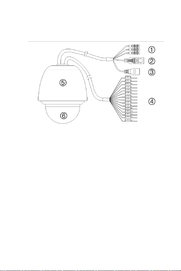
Camera description
Figure 1: Overview of the dome camera (pendant-mount
shown)
1. Power supply cord
Connect 24 VAC power supply
2. Video output
Connect the BNC connector to a CCTV monitor
3. Ethernet RJ45 connector. Connect to the network
devices
Connect to the PoE+ switch
4. Alarm input/outputs and audio in/out port
5. Housing
6. Bubble
Installation Guide 5
Page 6
Installing a camera
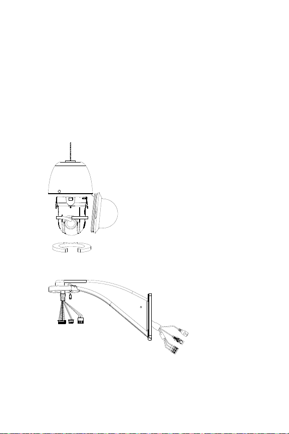
Pendant-mount camera
1. Prepare the mounting surface and install the camera
bracket.
2. Unscrew the bubble from the camera and remove the
protective tape from the PTZ module.
3. Press the two tabs on either side of the PTZ module
and remove the module from the camera housing.
4. Route the cables from the pendant bracket as shown
below.
V
4
2
V
C
4
A
2
C
A
N
E
E
R
G
/
K
W
C
O
A
L
L
L
B
E
D
Y
E
R
5. Attach the safety cable to the bracket and connect the
cables to the PCB of the module through the cable entry
hole on top of the housing.
6 Installation Guide
Page 7

Safety cable
Note: If alarm and audio input/output relays are to be
used, also connect them to the PCB of the module.
Caution: The safety cable is made of metal. Please
ensure that it does not touch the PCB of the module.
6. Attach the camera housing to the bracket using the
screws enclosed with the bracket.
7. Insert the PTZ module into the housing:
Position the tabs on the PTZ module by aligning the
arrow label on the module with those on the housing
(see below). The module should firmly snap into
position. If using a SD card, insert it into the module
before inserting the module into the housing.
8. Re-attach the bubble by screwing it to the housing.
Installation Guide 7
Page 8

9. See “Accessing the camera over the internet” on page
14 to configure the camera over the internet. Refer to
the Configuration Manual for detailed information.
Flush-mount camera
1. Drill a hole on the ceiling using the drill template.
2. Tie three safety cables (not supplied) to the safety
hooks on the camera and hang the camera from a
secure point.
3. Unscrew the bubble from the camera and remove the
protective tape from the PTZ module.
4. Press the two tabs on either side of the PTZ module
and remove it from the camera housing.
5. Route the cables from the bracket and connect them to
the PCB of the module through the cable entry hole on
the top of the housing.
Note: If alarm and audio input/output relays are to be
used, also connect them to the PCB of the module.
8 Installation Guide
Page 9

6. Adjust the height of the two housing tabs by turning the
screw on which they are attached. The distance (h) of
the tabs from the housing ring must be greater than the
thickness of the ceiling.
Housing tab
7. Make sure the housing tab is closed and then PUSH the
housing into the pass-through hole. Hold the housing
and fix it by screwing the housing tabs down to the
mounting surface
8. Insert the PTZ module into the housing:
Screw
9. Re-attach the bubble by screwing it to the housing.
Installation Guide 9
Page 10

10. Install the trim ring. Align the trim ring to the housing,
and insert the fix-pins to the holes. Then rotate the ring
clockwise to secure.
11. See “Accessing the camera over the internet” on page
14 to configure the camera over the internet. Refer to
the Configuration Manual for detailed information.
Surface-mount camera
The cables of PTZ camera can be routed either from the top
or the side of the housing. For the cables routed from the
top of the housing, you must drill a cable hole in the ceiling.
10 Installation Guide
Page 11

1. Use the mounting base as a template to mark four
screw holes onto the ceiling. If you route cables from
the top of the housing, mark the cable hole on the
ceiling and drill a hole.
Screw holes
Cable hole
2. Secure the mounting base to the ceiling with the set
screws.
3. Unscrew the bubble from the camera and remove the
protective tape from the PTZ module.
4. Press the two tabs on either side of the PTZ module
and remove it from the camera housing.
5. Route the cables from the bracket and connect them to
the PCB of the module through the cable entry hole on
the top or side of the housing.
Note: If alarm and audio input/output relays are to be
used, also connect them to the PCB of the module.
Installation Guide 11
Page 12

6. Install the housing onto the mounting base. Line up the
direction of the arrow on the housing with the spring end
of the mounting base. Push the housing upwards (A)
and then forwards (B) in the direction of the arrow.
When the housing is placed in position, the spring will
automatically snap into the lock clip firmly. Refer to the
figures below.
Line up
A. Push upward
B. Push forward
Lock clip
7. Insert the PTZ module into the housing:
12 Installation Guide
Page 13

8. Re-attach the bubble by screwing it to the housing.
Warning: After installation, the PTZ module will perform
a PTZ self-test and initializes with the power on. DO
NOT touch and move the camera while it is self-testing
and initializing.
9. See “Accessing the camera over the internet” on page
14 to configure the camera over the internet. Refer to
the Configuration Manual for detailed information.
Installation Guide 13
Page 14

Using the camera with an Interlogix NVR or
Hybrid DVR or another system
Please refer to the NVR/DVR user manuals for instructions
on connecting and operating the camera with these
systems.
Using the camera with TruVision Navigator
A camera must be connected to an Interlogix NVR or hybrid
DVR to be operated by TruVision Navigator. Please refer to
the TruVision Navigator user manual for instructions on
operating the camera with the TruVision Navigator.
Accessing the camera over the
internet
Use the web browser to access and control the camera over
the internet.
Note: Any changes made to the camera’s configuration only
apply to this camera.
Change the administrator password once the set-up is
complete. Only authorized users should be able to modify
camera settings.
To access the camera online:
1. In the web browser enter the camera’s IP address
(default is 192.168.1.70). The Login dialog box appears.
2. Enter your user name and password.
Default user name: admin
Default password: 1234
Click Login. The web browser screen appears in live
mode. The live screen is initially blank.
14 Installation Guide
Page 15

3. Click the Configuration tab on the top of the screen
and select the parameter to change
Figure 2: Example of a configuration window
Table 1: Overview of the Configuration panel
Configuration folders Description
System
Network
Video/Audio Defines recording parameters.
PTZ Defines the PTZ parameters.
Image
Security
Events
Defines device basic information including
SN and the current firmware version, time
settings, and maintenance parameters.
Defines the network parameters required
to access the camera over the internet.
Defines the image parameters, OSD
settings, overlay text, and privacy mask.
Defines who can use the camera, their
passwords and access privileges, RTSP
authentication, IP address filter, and telnet
access.
Defines motion detection, tamper-proof,
alarm input/output, exception, and
snapshot configuration.
Installation Guide 15
Page 16

Configuration folders Description
Storage
Defines recording schedule, storage
management and NAS configuration.
.
Specifications
Electrical
Voltage input 24 VAC, PoE+ (IEEE 802.3at)
Power consumption
Miscellaneous
Operating
temperature
Dimensions
Weight Pendant housing: 3,5 kg
Environmental rating Pendant housing: IP66
Pendant housing:
PoE: Max. 25 W
24 VAC: Max. 65 W
Flush housing: Max. 25 W
Surface housing: Max. 25 W
Pendant housing: PoE+ for -30 to 65 °C
24 VAC: -40 to +65 °C
Flush housing: -10 to +50 °C
(14 °F to 122 °F)
Surface housing: -10 to +50 °C
(14 to 122 °F)
Pendant housing: Ø 220 × 266 mm
Flush housing: Ø 206 × 251 mm
Surface housing: Ø 180 × 240 mm
Flush housing: 3 kg
Surface housing: 2,5 kg
Flush housing: IP54
Surface housing: IP54
16 Installation Guide
Page 17

Pin definitions
There are eight wires on a standard UTP/STP cable and
each wire is color-coded. The following shows the pin
allocation and color of straight and crossover cable
connection:
Figure 3: Straight-through cable
1 White/Orange White/Orange 1
2 Orange Orange 2
3 White-Green White-Green 3
4 Blue Blue 4
5 White/Blue White/Blue 5
6 Green Green 6
7 White/Brown White/Brown 7
8 Brown Brown 8
Figure 4: Cross-over cable
1 White/Orange White/Orange 1
2 Orange Orange 2
3 White-Green White-Green 3
4 Blue Blue 4
5 White/Blue White/Blue 5
6 Green Green 6
7 White/Brown White/Brown 7
8 Brown Brown 8
Please make sure your connected cables have the same
pin assignment and color as above before deploying the
cables in your network.
Installation Guide 17
Page 18

18 Installation Guide
Page 19

Page 20

 Loading...