

Page 1

P/N TVR40 uman-EN • REV 2.0 • ISS 30SEP11
TruVision DVR 40 User
Manual
Page 2

Copyright
© 2011 UTC Fire & Security. All rights reserved.
Trademarks and patents
Interlogix, TruVision name and logo are trademarks of UTC Fire & Security.
Other trade names used in this document may be trademarks or registered trademarks
of the manufacturers or vendors of the respective products.
Manufacture
r
Authorized EU manufacturing representative:
UTC Fire & Security B.V.
Kelvinstraat 7, 6003 DH Weert, The Netherlands
Certification
FCC compliance
Class A: This equipment has been tested and found to comply with the limits for a Class
A digital device, pursuant to part 15 of the FCC Rules. These limits are designed to
provide reasonable protection against harmful interference when the equipment is
operated in a commercial environment. This equipment generates, uses, and can radiate
radio frequency energy and, if not installed and used in accordance with the instruction
manual, may cause harmful interference to radio communications. Operation of this
equipment in a residential area is likely to cause harmful interference in which case the
user will be required to correct the interference at his own expense.
European Union directives
12004/108/EC (EMC directive): Hereby, UTC Fire & Security declares that this device is
in compliance with the essential requirements and other relevant provisions of Directive
2004/108/EC.
2002/96/EC (WEEE directive): Products marked with this symbol cannot be disposed of
as unsorted municipal waste in the European Union. For proper recycling, return this
product to your local supplier upon the purchase of equivalent new equipment, or
dispose of it at designated collection points. For more information see:
www.recyclethis.info.
2006/66/EC (battery directive): This product contains a battery that cannot be disposed
of as unsorted municipal waste in the European Union. See the product documentation
for specific battery information. The battery is marked with this symbol, which may
include lettering to indicate cadmium (Cd), lead (Pb), or mercury (Hg). For proper
recycling, return the battery to your supplier or to a designated collection point. For more
information see: www.recyclethis.info.
Contact information
For contact information, see www.interlogix.com or
Page 3

i
Content
Product overview...........................................................................................................1
Product description..............................................................................................................................1
Unpacking the TruVision DVR 40 and its accessories........................................................................1
Installation environment ......................................................................................................................2
Installation......................................................................................................................3
Connecting the devices .......................................................................................................................3
Connecting alarm inputs and outputs..................................................................................................4
Connecting the TVR 40 to a PC..........................................................................................................4
Setting up a PTZ dome camera ..........................................................................................................5
Connect a TVR 40 to a PTZ dome camera and keypad ...........................................................5
Local control of PTZ dome camera ...........................................................................................5
Network control of PTZ dome camera ......................................................................................5
Configure the PTZ protocols for Interlogix cameras..................................................................6
Wiring the TVK-505U keypad..............................................................................................................9
Monitor connections ............................................................................................................................9
Controlling the TVR 40................................................................................................11
Using the front panel .........................................................................................................................12
Using the IR remote control...............................................................................................................14
Using the mouse ...............................................................................................................................15
Using the Web browser .....................................................................................................................16
Windows Vista and 7 users.....................................................................................................16
Accessing the Web browser....................................................................................................17
Web browser overview ............................................................................................................17
Using the Web browser to configure the device......................................................................18
Basic operations..........................................................................................................21
Turning on the TVR 40 ......................................................................................................................21
Logging in using PINs .......................................................................................................................22
Live mode..........................................................................................................................................22
Selecting a monitor............................................................................................................................24
Viewing in multiscreen.......................................................................................................................24
Manual recording...............................................................................................................................25
Searching and playing back recorded video .....................................................................................27
Control playback progress.......................................................................................................27
Search recorded video ............................................................................................................28
Playback recorded video .........................................................................................................30
Archiving recorded files .....................................................................................................................31
Quick archive...........................................................................................................................31
Manually select files to archive................................................................................................31
Automatically backup recorded files........................................................................................33
Controlling a PTZ camera .................................................................................................................34
Manually acknowledging an alarm ....................................................................................................36
Overview of the menu structure ........................................................................................................37
Navigating through a menu screen .........................................................................................38
Turning off the TVR 40 ......................................................................................................................39
Page 4

ii
Display settings...........................................................................................................41
Selecting a language.........................................................................................................................42
Setting the device ID .........................................................................................................................43
Setting the PIN requirement..............................................................................................................43
Displaying the status bar ...................................................................................................................43
Menu timeout.....................................................................................................................................44
Selecting video standard ...................................................................................................................44
Video scaling .....................................................................................................................................44
Menu transparency............................................................................................................................45
Defining VGA resolution ....................................................................................................................45
Setting system time and date............................................................................................................45
Multiscreen and sequencing..............................................................................................................46
Camera settings...........................................................................................................49
Setting up the camera title.................................................................................................................50
Positioning the camera title ...............................................................................................................50
Modifying the image quality...............................................................................................................51
Displaying the current time and date on-screen................................................................................52
Motion detection ................................................................................................................................53
Privacy masks ...................................................................................................................................57
Viewing a camera tamper alarm .......................................................................................................59
Setting up a video loss alarm ............................................................................................................61
Recording settings......................................................................................................63
Configuring the recording settings ....................................................................................................63
Responding to full HDD.....................................................................................................................64
Using an external storage device for backup ....................................................................................65
Auto delete mode (ADM)...................................................................................................................65
Modifying the recording parameters of a camera .............................................................................65
Setting up a camera’s recording schedule........................................................................................68
Network settings..........................................................................................................71
Network settings................................................................................................................................72
E-mail settings...................................................................................................................................73
Advanced IP settings.........................................................................................................................74
PPPoE dial-up settings......................................................................................................................76
DDNS settings...................................................................................................................................77
Alarm settings..............................................................................................................79
Alarm relay outputs ...........................................................................................................................79
External alarm input ..........................................................................................................................80
External alarm output ........................................................................................................................82
Notification settings ...........................................................................................................................84
PTZ settings.................................................................................................................85
Description of preset, preset tour, and shadow tour options.............................................................86
PTZ settings ......................................................................................................................................86
Using preset positions .......................................................................................................................87
Using shadow tours...........................................................................................................................90
User settings................................................................................................................91
Overview of users and PINs..............................................................................................................92
Page 5

iii
Modifying a user’s PIN ......................................................................................................................93
Adding a new user.............................................................................................................................93
Modifying operational rights ..............................................................................................................94
Setting up a MAC ..............................................................................................................................95
Deleting a user ..................................................................................................................................96
System settings...........................................................................................................97
Capturing text insertions....................................................................................................................98
Handling transaction information.....................................................................................................100
Configuring the RS-232...................................................................................................................102
Upgrading the firmware...................................................................................................................103
Restoring factory default settings....................................................................................................103
Managing the hard drive..................................................................................................................104
Viewing system logs........................................................................................................................105
Rebooting the TVR 40.....................................................................................................................106
Viewing system information.............................................................................................................107
Troubleshooting and support...................................................................................109
Troubleshooting your system ..........................................................................................................109
Contacting technical support ...........................................................................................................110
Appendix 1: Specifications.......................................................................................111
Index...........................................................................................................................113
Page 6

iv
Page 7

TruVision DVR 40 User Manual 1
Product overview
Product description
The second generation of TVR 40 uses H.264, the latest video compression standard. This
standard offers 25 frames per channel per second at CIF resolution. This compression
technology delivers compact but excellent quality images.
The TruVision DVR 40 offers 4, 8 or 16 channels of analog recording, all up to 4CIF resolution
(704 x 576). The dual streaming functionality allows the user to set up different settings for
recording and streaming video. TVR 40 supports both variable bit rate and variable frame rate.
The dual streaming functionality allows the user to set up different settings for recording and
streaming video. TruVision DVR 40 incorporates Triplex functionality for simultaneous
transmitting, viewing live video, and recording.
The TruVision DVR 40 series embedded digital video recorder is a digital surveillance product. It
uses an embedded microcontroller TVR 40 (MCU) and an embedded real-time operating system
(RTOS), combining the most advanced technology in the information industry, such as video and
audio encoding/decoding, hard disk recording, and TCP/IP. The firmware is burned into the
flash, making it more stable and reliable.
TruVision DVR 40 series has the features of both a digital video recorder (DVR) and a digital
video server (DVS). It can be used as a standalone device but also to build a powerful
surveillance network, such as widely used in the banking, telecommunications, manufacturing,
and transportation sectors.
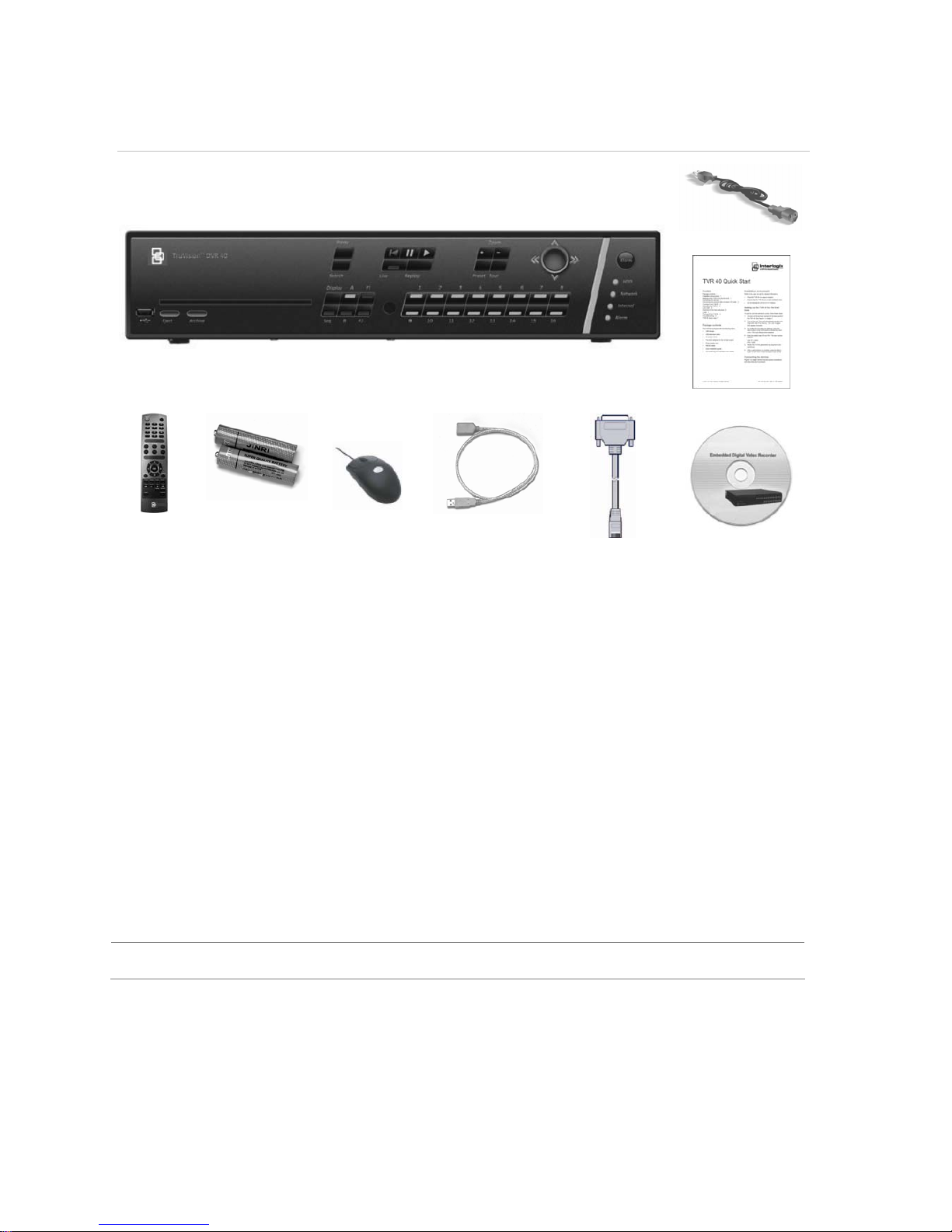
Unpacking the TruVision DVR 40 and its accessories
When you receive the product check the package and contents for damage, and that all the
items are included. There is an item list in the package. If any of the items are damaged or
missing, please contact your local supplier.
Page 8
2 TruVision DVR 40 User Manual
Figure 1: Items shipped with product
AC mains cable
Quick Start Guide
IR remote
control
AAA batteries USB mouse USB extension
cable
RS-232 cable CD with
documentation &
utilities
Installation environment
Ventilation: Do not block any ventilation openings. Install in accordance with the
manufacturer’s instructions. Ensure that the location planned for the installation of the unit is well
ventilated. Regularly clean the unit by gently brushing it.
Temperature: Consider the TruVision DVR 40’s operating temperature (-10 to 50°C) and non-
condensing humidity specifications (10 to 90%) before choosing an installation location.
Extremes of heat or cold beyond the specified operating temperature limits may cause the
TruVision DVR 40 to fail. Do not install the unit on top of other hot equipment. Leave space
between rack mounted units.
Moisture: Do not use the unit near water. Moisture can damage the internal components. To
reduce the risk of fire or electric shock, do not expose this unit near to rain or moisture.
Chassis: Other equipment may be placed on top of the unit if it weighs less than 16 kg.
WARNING: Before installing the unit, please ensure that the power to the unit is switched off.
Page 9
TruVision DVR 40 User Manual 3
Installation
This section describes how to connect the TruVision DVR 40 unit.
Connecting the devices
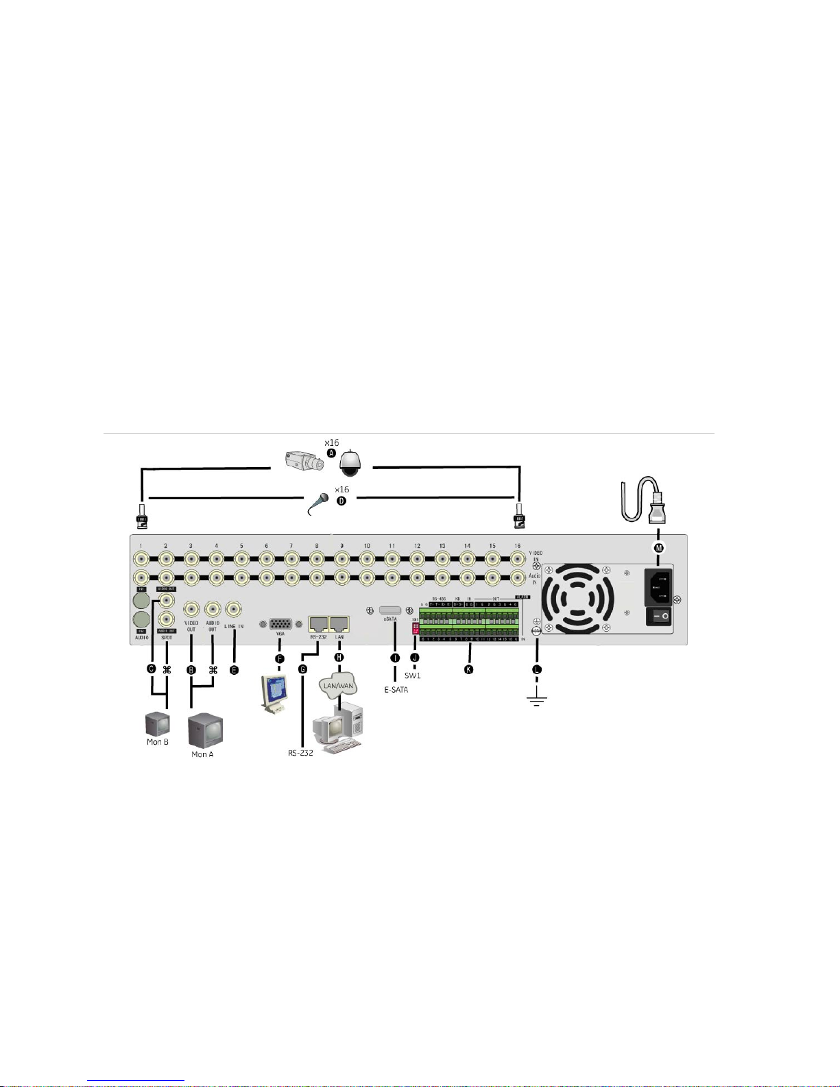
Figure 2 shows the back panel connections and describes each connector. There are variations
between the different model types.
Figure 2: TruVision DVR 40 back panel connections (16-channel model shown)
Required connections
A. Connect up to 16 cameras to the standard BNC video inputs.
Note: If a camera is incorrectly connected to the TVR 40, the monitor shows a Video Loss message. Check the
connection and reconnect the camera if necessary.
B. Connect monitor A (main) to the output VIDEO OUT. Connect the audio output () to AUDIO OUT if required.
You can use either analog or VGA output. Both outputs will display the same video information.
Optional connections
C. Connect a spot monitor (Mon B) to the TVR 40. Connect the monitor video to VIDEO OUT. Connect the
monitor audio (if used) to AUDIO OUT ().
D. Connect up to 16 audio signals to the standard BNC audio inputs (315 mV).
E. For future use.
F. Connect the VGA display (max. 1024 × 768 @ 60 Hz).
G. Connect an ATM or optional ProBridge using the supplied RS-232 cable.
H. Connect the network devices.
Page 10
4 TruVision DVR 40 User Manual
I. Connect the E-SATA for archive and storage expansion.
J. Terminate the line using this RS-485 switch. The default setting is OFF.
K. Connect the external data and alarm input/output (I/O) cable. See Figure 3 on page 4 for more information.
L.
Connect the TVR 40 to ground.
Power connection
M. Connect the power cord to the TVR 40. Be sure all devices are connected and turned on before you turn on the
TruVision DVR 40.
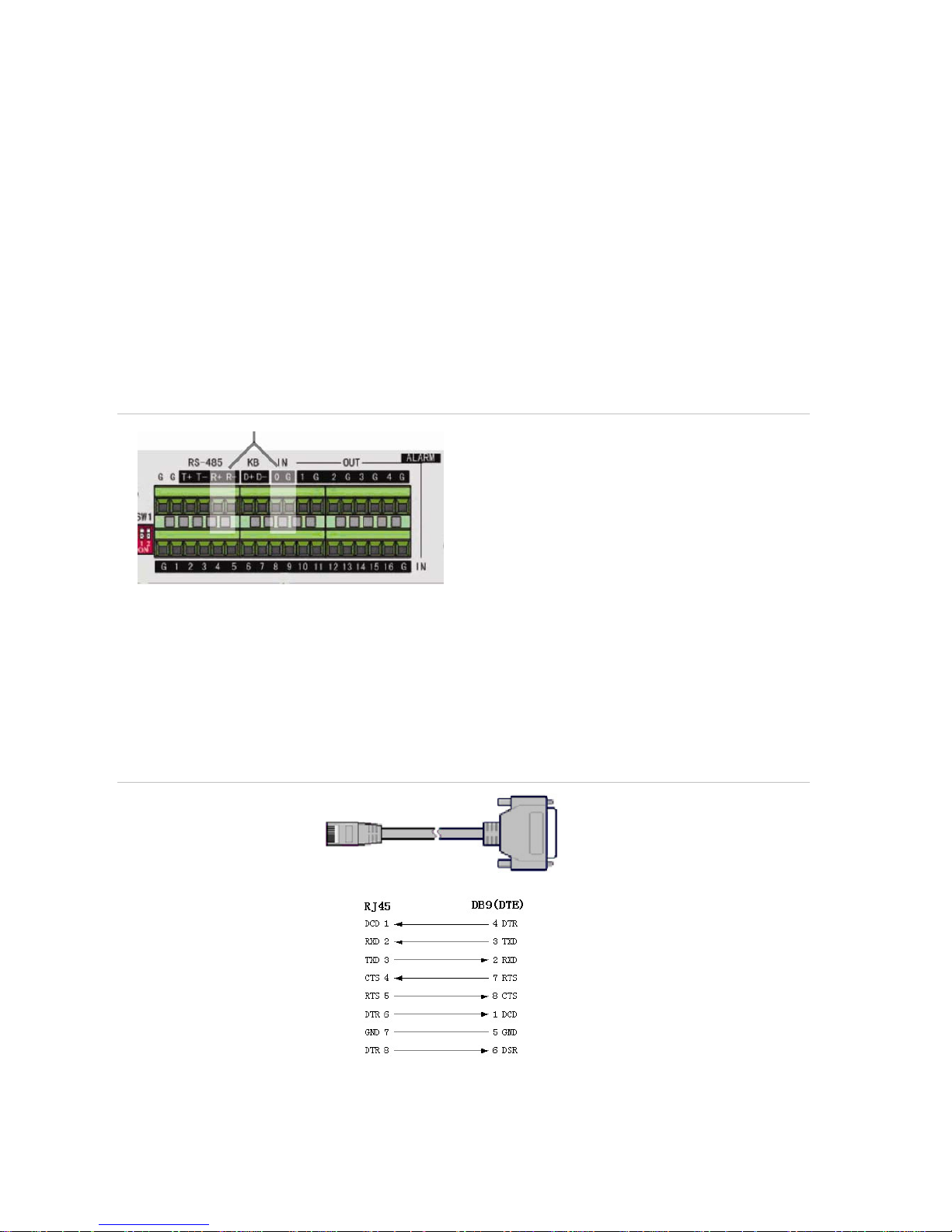
Connecting alarm inputs and outputs
Figure 3: Connecting the external data and alarm I/O cable
Not used
RS-485 T+ T-: Connect the PTZ camera
KB D+/D-: Connect keypad
Alarm output port:
1-G to 4-G: 4 relay ports
Alarm input port:
G: Common ground)
1 to 16: Alarm inputs, NO/NC supported
Connecting the TVR 40 to a PC
Use a RS-232 cable to connect the unit to a PC. Figure 4 describes the pin connections to use
when connecting the serial port of the TVR 40 to a device using a DB9 connector such as on a
PC.
Figure 4: The pin connections of a RS-232 cable
TVR 40
PC
Pin configuration
Page 11
TruVision DVR 40 User Manual 5
Setting up a PTZ dome camera
Use the USB mouse provided or the optional KTD-405 keypad for local telemetry control. If
using the TVR 40 over a network, use the web browser to control the PTZ dome cameras.
The supported protocols are: GE, Pelco-D, and Pelco-P
For information on setting up the PTZ protocols and presets, see “PTZ settings” on page 86.
Connect a TVR 40 to a PTZ dome camera and keypad
Use the input/output box that is supplied with the keypad to connect a keypad to the TVR 40.
The keypad can be connected to a PTZ camera for local control or for control over the network.
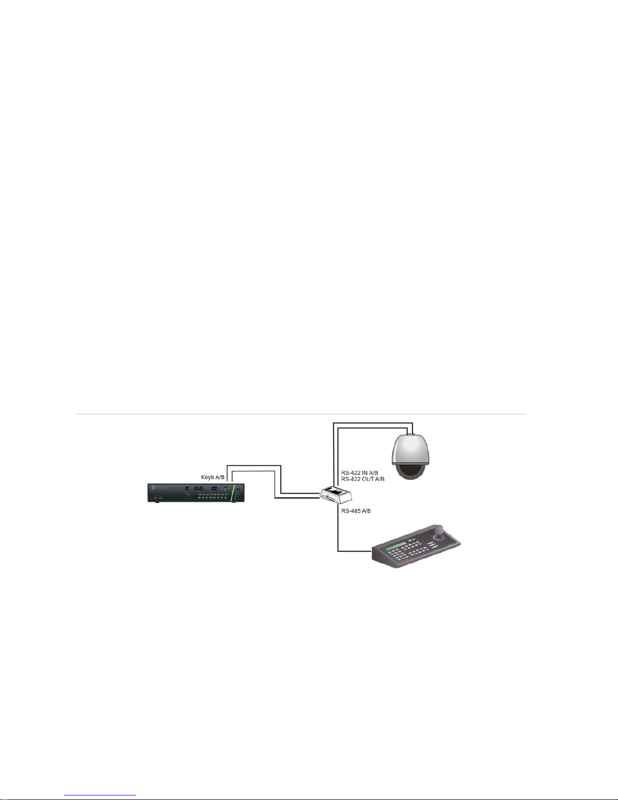
Local control of PTZ dome camera
If you simply want to configure a PTZ dome camera using a keypad, connect the keypad as
shown in Figure 5 below. This setup only functions with the supported PTZ cameras listed in
Figure 5 below. Third-party PTZ cameras are not supported.
This setup d
oes not let you control or configure the PTZ dome cameras using the DVR front
panel, remote control, Web browser or remote software. However, it can be useful to use as a
temporary setup in order to fully configure the PTZ cameras to meet customer requirements.
Once the camera installation is complete, rewire the setup for control over the network. (see
Figure 6 on page 6). The PTZ dome cameras can then be controlled using the DVR front panel,
remote control, Web bro
wser or remote software.
Figure 5: Connecting a keypad to the TVR 40 for local c ontrol of a PTZ dome camera
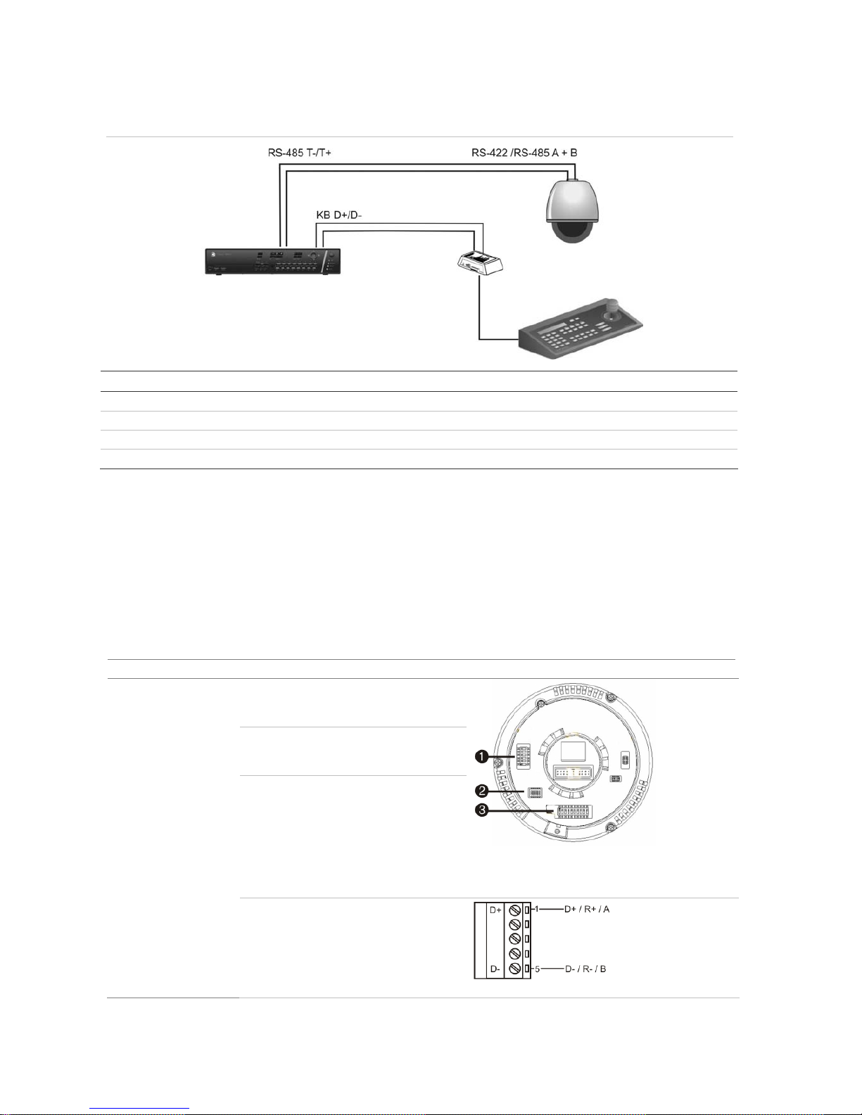
Network control of PTZ dome camera
This is the preferred setup (Figure 6 on page 6.) Any PTZ dome camera to be controlled as the
DVR is doing the PTZ protocol translation. However, this setup provides only limited dome
configuration.
Page 12
6 TruVision DVR 40 User Manual
Figure 6: Connecting a TVR 40 to a PTZ dome camera
Connection Serial port TVR 40
I/O box from keypad: White D+
Yelow D-
PTZ camera: RS-422/RS-485 A T+
RS-422/RS-485 B T-
Configure the PTZ protocols for Interlogix cameras
Before the PTZ cameras are assembled in their housings, set their protocol and address DIP
switches for the TVR 40. See Table 1 below for the different Interlogix PTZ camera
configuratio
ns.
If you are using PTZ cameras from another company, please refer to their configuration
instructions.
Table 1: Configuring Interlogix PTZ cameras
Camera Switch setting
TruVision Mini
Dome 12X PTZ:
Indoor Dome
Protocol DIP
switches:
000000
RS-485
communication DIP
switches:
0000000000
Camera ID DIP
switches:
Select the
camera ID
DIP switch
address as
required
1. Protocol DIP switches;
2. RS-485 communication DIP switches;
3. Camera ID DIP switches
RS-485 data connector:
Page 13
TruVision DVR 40 User Manual 7
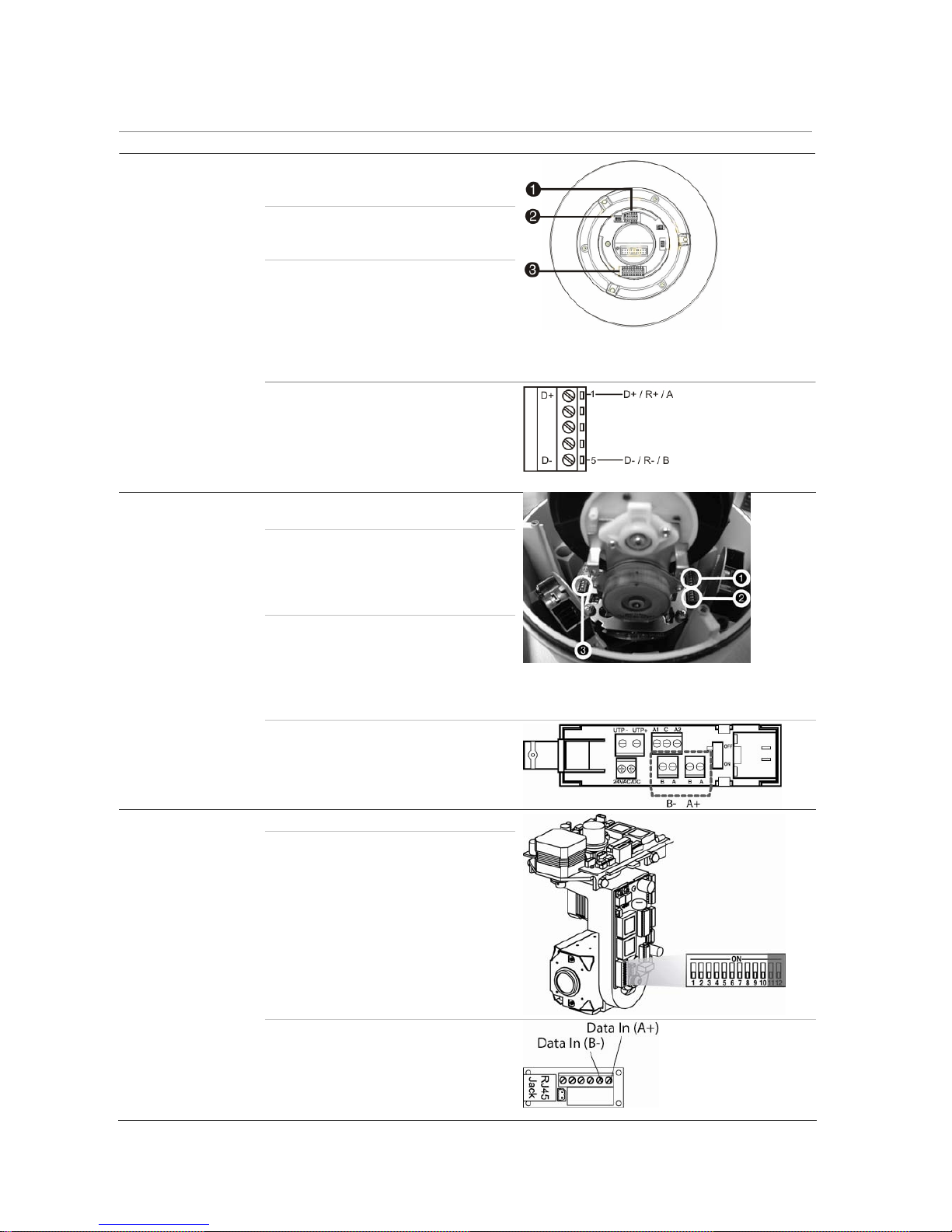
Camera Switch setting
TruVision Mini
Dome 12X PTZ:
Outdoor Dome
Protocol DIP
switches:
000000
RS-485
communication DIP
switches:
0000000000
Camera site ID DIP
switches:
Select the
camera ID
DIP switch
address as
required.
1. Protocol DIP switches;
2. RS-485 communication DIP switches;
3. Camera site ID DIP switches
RS-485 data connector:
TruVision Dome
16X PTZ
Protocol DIP
switches:
0111
Address DIP
switches:
Select the
camera ID
DIP switch
address as
required.
Baud rate: 0000
1. Address switches;
2. Baud switches;
3. Protocol switches
RS-485 data connector:
CyberDome Protocol switches: NA
Address switches: Select the
camera ID
DIP switch
address as
required.
RS-485 data connector:
Page 14
8 TruVision DVR 40 User Manual
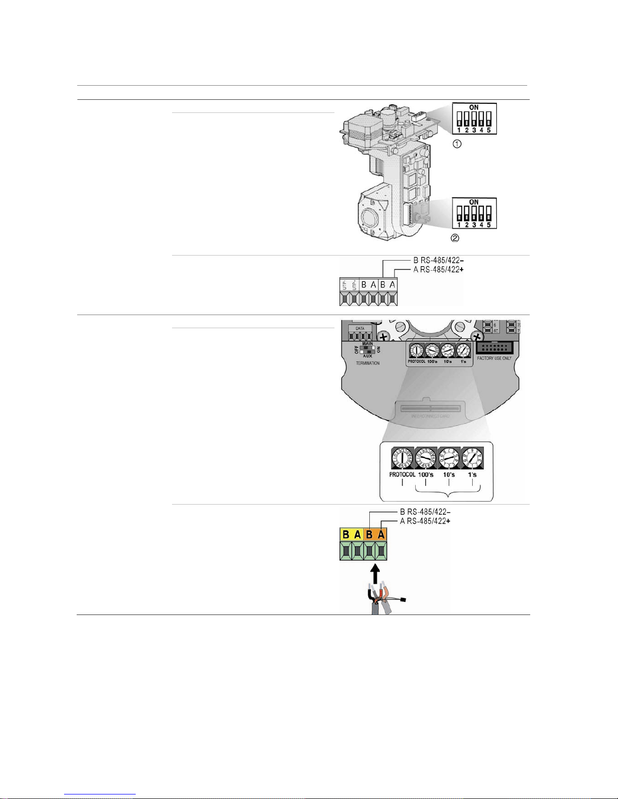
Camera Switch setting
UltraView PTZ
Protocol switches: 01000
Address switches: Select the
address
switch
address as
required.
1. Protocol switches; 2. Address switches
RS-485 data connector:
Legend Protocol switches: 5
Address switches: Select the
camera ID
DIP switch
address as
required.
RS-485 data connector:
Page 15
TruVision DVR 40 User Manual 9
Wiring the TVK-505U keypad
The keypad uses RS-485 simplex wiring. The signal is transferred by a single twisted pair line.
An unshielded CAT5 network cable is recommended for normal applications. Use a shielded
CAT5 cable if the cables could be exposed to interference.
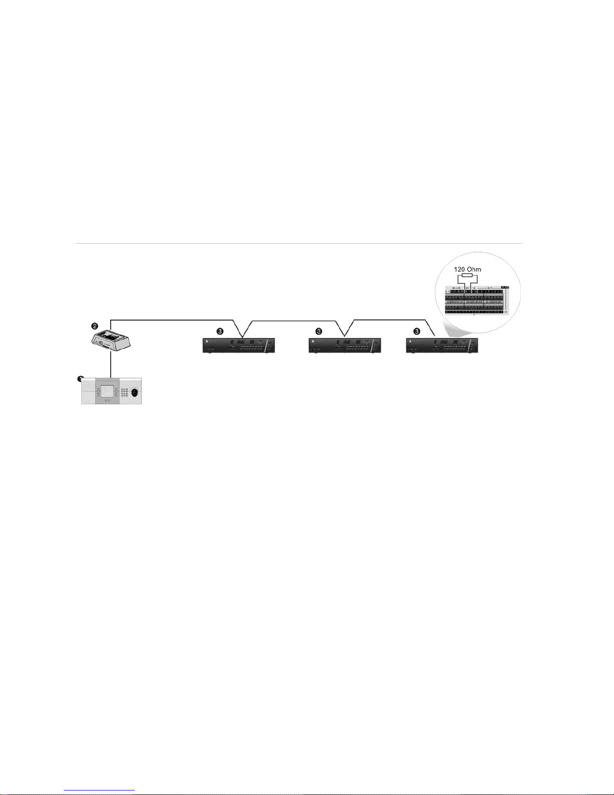
The maximum number of devices that can be installed in one bus is 255, with a maximum cable
length of 1200 m. The cable length can be expanded using a signal distributor.
Both the first and the last device in series should be terminated with 120 Ohm resistance to
minimize line reflections. See Figure 7 below.
Figure 7: RS-485 bus serial wiring
1. Keypad; 2. I/O box; 3. TVR 40
Monitor connections
Connect the unit to the monitors via 75-ohm video coaxial cables with BNC connectors. The unit
provides a 1 Vpp CVBS signal.
Page 16

10 TruVision DVR 40 User Manual
Page 17

TruVision DVR 40 User Manual 11
Controlling the TVR 40
There are four ways to control the TVR 40 menu options:
Front panel control
IR remote control
Mouse control
Web browser control
These options are described in the following sections.
Page 18
12 TruVision DVR 40 User Manual
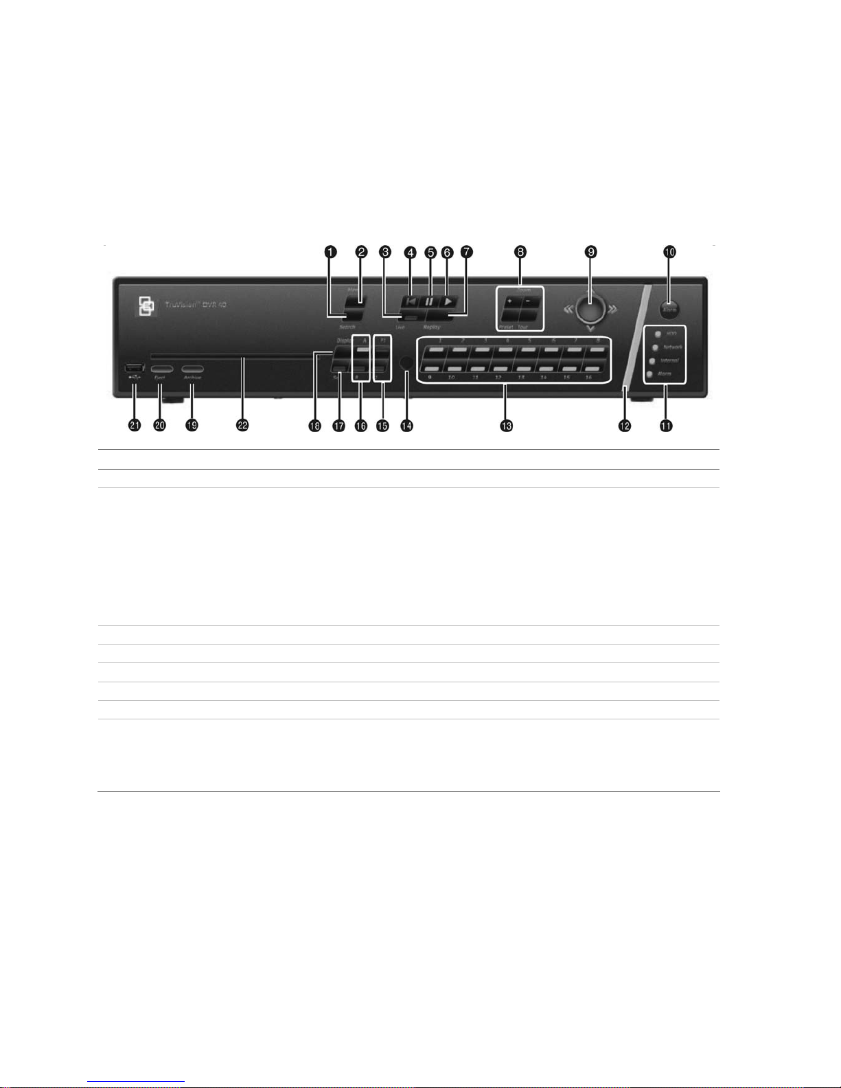
Using the front panel
The buttons on the front panel control all functions. The LED indicators light up or flash to alert
you to various conditions. The functions available can be limited by setting passwords. See
Figure 8.
Figure 8: Front panel
Item Name Description
1. Search Press to open the Playback menu to search for and playback recorded videos.
2. Menu This button has several functions depending on the operation used.
In Live mode:
Press to open the Main menu.
In menu mode:
If an edit box of a menu option is selected, press the button to exit the option.
If a check box or list box of a menu option is selected, press the button to exit
the option and return to the Main menu. Press again to return to live mode. Any
changes made will not be saved.
3. Live Press to return to live mode.
4. Playback Press to playback the oldest file in the system.
5. Playback Pause Press to pause playback.
6. Instant Playback Press to playback the most recent three minutes of video recorded.
7. Replay Press to playback current file.
8. PTZ Control Displays the PTZ control of the selected camera, if PTZ is supported.
Zoom +/-: Press to zoom camera image in and out.
Preset: Select a pre-programmed Preset option.
Tour: Select a pre-programmed Shadow Tour option.
Page 19

TruVision DVR 40 User Manual 13
Item Name Description
9. Trigger-point
joystick
Use to select options in a menu and to control playback. Press for Enter. LED
arrows are lit when the jog is active.
In live mode:
Press to enter PTZ mode.
In menu mode:
Move the joystick left/right and up/down to position cursor in menu screen.
Press for Enter.
In PTZ mode:
Move the joystick left/right and up/down to position cursor in menu screen.
Press for Enter.
In playback mode:
Move left: Decrease speed.
Move right: Increase speed.
Move up: Jump forwards 30 seconds.
Move down: Jump backwards 30 seconds.
10. Manual Alarm Press to manually acknowledge an alarm.
11. Status LEDs
HDD: Green – Hard drive is working correctly.
Red – Fault.
Network: Green – Network working correctly.
Red – Fault.
Internal: Green – Device is working correctly.
Red – There are internal errors.
Alarm: Green – No external alarm.
Red – indicates an external alarm status.
12. Alarm indicator Flashes red when there is an alarm.
13. Cameras Each camera has its own numeric button.
No light - Camera is disabled.
Green - Connected and working correctly
Red (flashing) - Camera is in alarm mode.
Red (steady) - Video loss.
14. IR remote receiver This is the receiver for the IR remote control.
15. F1 / F2 Press to select F1 or F2 functions. The functions vary depending on the
operation used such as:
- Select displayed time format.
- Archive recordings or specific segment of a recording.
- Select motion detection and privacy mask zones on-screen.
16. Monitor selection Press to toggle between monitors A and B.
17. Seq Press to sequence cameras in live mode.
18. Display Press to view multiscreen format.
19. Archive Press to open the Search Archive menu.
20. Eject Push to eject CD-ROM from the drive.
21. USB Insert USB device such as a mouse or storage media.
22. DVD slot Insert CD or DVD disk.
Page 20
14 TruVision DVR 40 User Manual
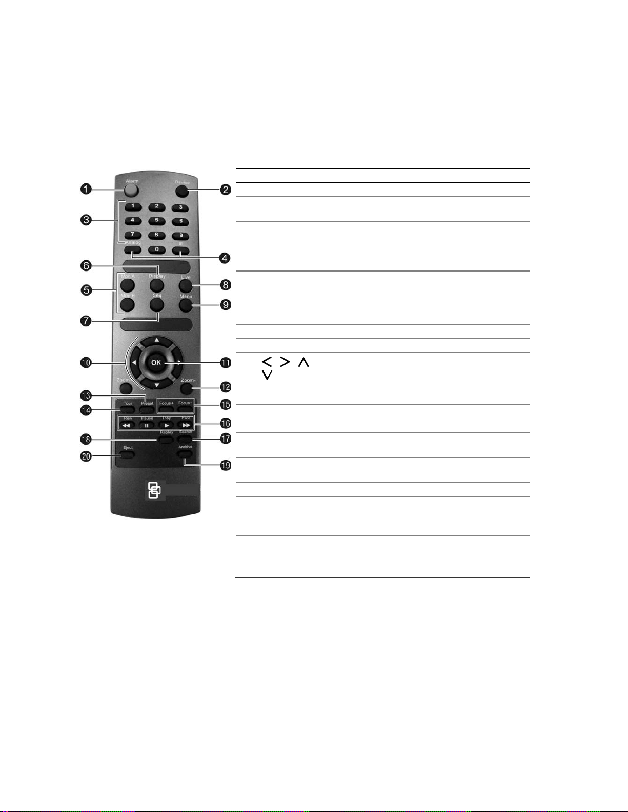
Using the IR remote control
The IR remote control operation is similar to the front panel operation.
Figure 9: Description of the IR remote control
Item Description
1. Alarm Acknowledge an alarm.
2. Device Enable/disable the IR remote control to control the
TVR 40.
3. Numeric
buttons
Select a camera, and enter a number in a menu
option.
4. Analog and IP Analog is equivalent to FI, and IP to F2, on the front
panel.
5. Mon A and
Mon B
Toggle between monitors A and B.
6. Display Toggle between the multiscreen views.
7. Seq Start /stop sequencing.
8. Live Return to live mode.
9. Menu Activate the main menu.
10. , , ,
In Menu mode: Use left or right arrow buttons to
select and up or down arrow buttons to edit entry.
In PTZ mode: Use to control PTZ.
In Playback mode: Use to control playback speed.
11. OK Confirm selection.
12. Zoom + and - Use to control zoom of camera lens.
13. Preset Enter preprogrammed three-digit code to call up a
preset.
14. Tour Enter preprogrammed three-digit code to call up
shadow tour.
15. Focus + and - Use to control focus of camera lens.
16. Playback
control
Use to control playback (Rewind, Pause, Play, and
Fast Forward).
17. Search Open the Search menu.
18. Replay Replay the selected file from the beginning.
19. Archive Open the Quick Archive menu.
20. Eject Eject the CD or DVD disk.
To insert batteries into the IR remote control
1. Remove the battery cover on the IR remote control.
2. Insert the batteries. Observe the correct battery polarity (+ and -).
3. Replace the battery cover.
To connect the remote control to the TVR 40
1. Press the Device button on the IR remote control.
2. Enter the device ID. The TVR 40 default ID is 1.
Note: See “Setting the device ID” on page 43 for information on how to change the device ID.
Page 21

TruVision DVR 40 User Manual 15
To disconnect the IR remote control
1. Press the Device button on the IR remote control. It cannot now be used to operate the DVR.
When the IR remote control does not function properly
Check the battery polarities
Check that the batteries are sufficiently charged
Check that the IR remote control sensor is not masked
If the problem persists, please contact your local supplier.
Using the mouse
Use the USB mouse provided with the TVR 40. It can carry out the same operations as the front
panel and remote control.
Connect the mouse to the DVR by simply plugging the mouse USB connector into the USB port
on the TVR 40. The mouse is immediately operational.
To use the mouse in live mode
Scroll forwards and backwards between cameras: When in full-screen mode use the
scroll button on the mouse to scroll forwards and backwards through the cameras.
Toggle between full-screen and multiview: When in multiview double-click the left button
of the mouse on a camera to open it in full-screen view. Double-click again to return to
multiview.
To access the mouse control menu
In live mode right-click the mouse to open its control menu. It has eight menu options, which
are listed in Table 2.
Table 2: Mouse control menu
Menu option Description
Menu Jump to the main menu.
Camera Select a specific individual camera.
Multi Screen Select multiview. The multiview selection presented depends on the number of
cameras connected to the TVR 40.
PTZ Control Control a PTZ camera. See Table 4 on page 35 for the description of the PTZ control
icons.
Right-click the mouse to get the following options:
• Channel: Select the camera to control
• Preset: Select a preset number to use
• Exit: Return to live mode
Page 22

16 TruVision DVR 40 User Manual
Menu option Description
Instant Replay Get an instant replay of the last five minutes recorded from all cameras in either full-
screen view or multiview. See section ““Playback recorded video” on page 30 for more
information.
During the playback right-click the mouse to jump to the Playback menu.
Search Jump to the Playback menu. See “Searching and playing back recorded video” on
page 27. Select for recordings with specific criteria, such as particular camera, type of
event, time, and text.
Right-click the mouse to return to live mode.
Manual Record Manual Record menu screen appears. See “Manual recording” on page 25.
Status Bar Toggle the on-screen status bar on/off.
Swap Monitor Toggle between monitors A and B.
Using the Web browser
This section describes how you can use the Web browser interface to configure the device,
playback recorded video, search through event logs, and control a PTZ dome camera.
Windows Vista and 7 users
Internet Explorer for Windows Vista and Windows 7 operating systems have increased security
measures to protect your PC from any malicious software being installed. When using the
TVR 40 Web browser interface, you can install ActiveX controls to connect and view video using
Internet Explorer.
To have complete functionality of the Web browser interface and the DVR player with Windows
Vista and Windows 7, do the following:
Run the browser interface and the DVR player application as an administrator in your
workstation
Add the DVR’s IP address to your browser’s list of trusted sites
To add the DVR’s IP address to Internet Explorer’s list of trusted sites
1. Open Internet Explorer.
2. Click Tools, and then Internet Options.
3. Click the Security tab, and then select the Trusted Sites icon.
4. Click Sites.
5. Clear the “Require server verification (https:) for all sites in this zone” box.
6. Enter the IP address or DDNS name in the “Add this website to the zone” field.
7. Click Add, and then click Close.
8. Click OK in the Internet Options dialog screen.
9. Connect to the TVR 40 for full browser functionality.
Page 23
TruVision DVR 40 User Manual 17
Accessing the Web browser
To access the TVR 40, open a Web browser and enter the IP address assigned to the TVR 40,
as a Web address. On the logon screen, enter the default user ID and password.
Note: Only one DVR can be viewed per browser.
User ID: admin
Password: 1234
The Web browser uses the following ports.
• IP address - 192.168.1.82
• Subnet mask - 255.255.255.0
• Gateway address - 192.168.1.1
• Video Port: 8000
• HTTP Port: 80
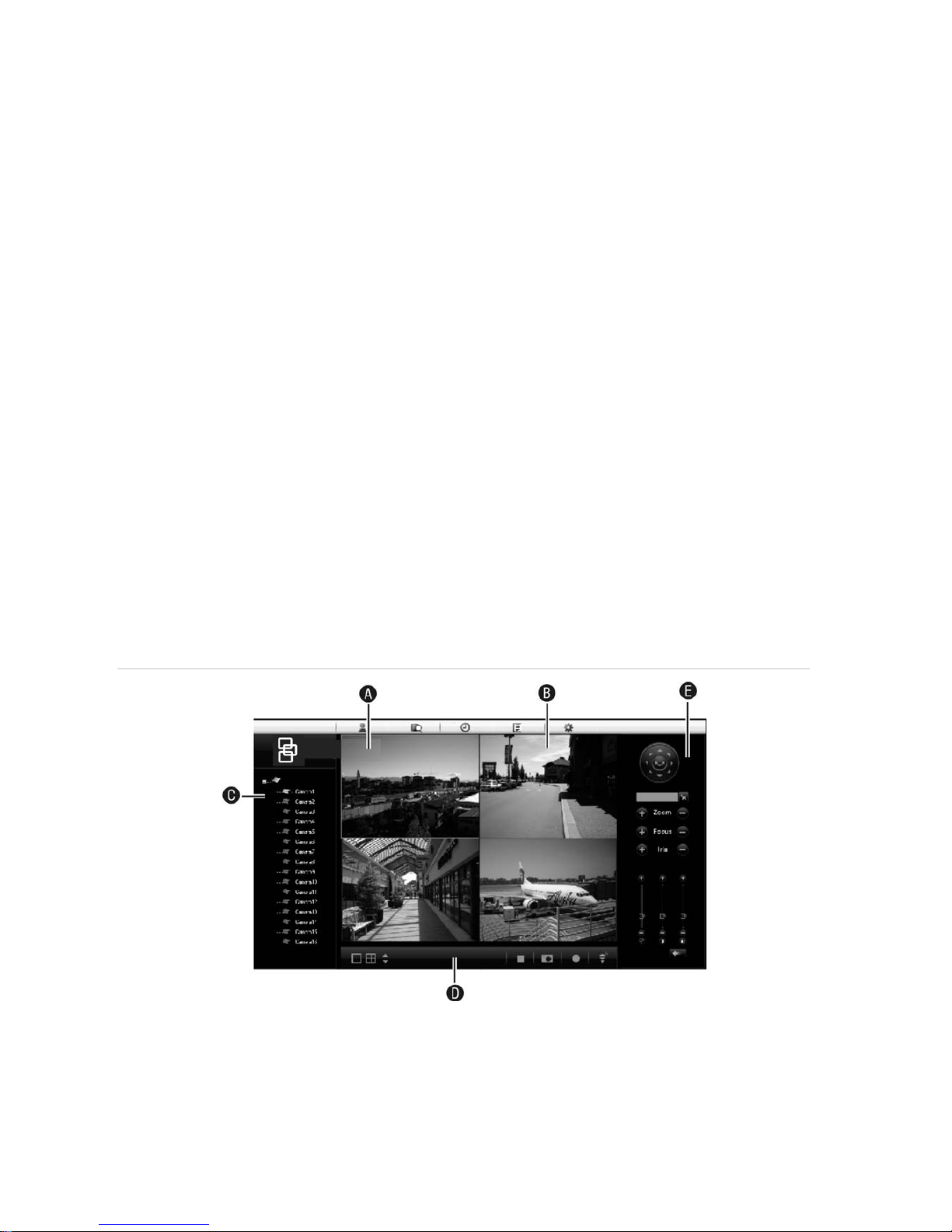
Web browser overview
The TVR 40 Browser lets you easily view, record, and playback video as well as manage all
aspects of the system from any Internet location. It has easy-to-use controls that give you quick
access to the functions you require. See Figure 10 below for the layout.
You can also specify set
tings on the Web browser interface to optimize video playback and
recording performance when operating in a low or limited bandwidth environment
Figure 10: TVR 40 Browser layout (Live mode shown)
A.
Viewer: View live and recorded video.
B.
Navigation bar: Access live and playback video. Explore the TVR 40 internal log, and carry out
comprehensive remote maintenance.
C.
Navigator: Access all TVR 40 cameras.
D.
Viewer controller: View or edit the properties of the currently selected objects in the Navigator.
E.
Camera controller: Control PTZ cameras or edit properties of the currently selected cameras.
Page 24
18 TruVision DVR 40 User Manual
Using the Web browser to configure the device
Click Config on the menu bar to display the configuration screen. There are two ways to
configure the DVR: Local and Remote.
Local configuration
Local configuration lets you define communication and network parameters such as protocol
type, maximum file size, stream type, network transmission settings. You can also specify the
directory locations for saving recorded and playback video, captured images, and downloaded
files.
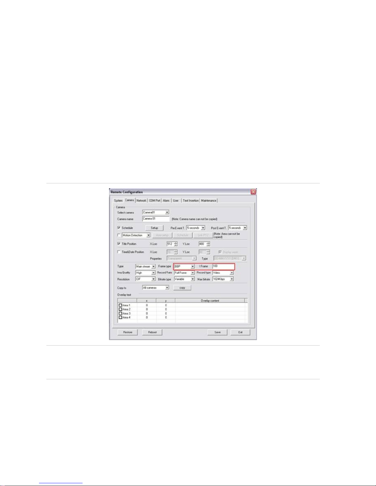
Remote configuration
Remote configuration lets you remotely configure the following DVR settings:
Note: The configuration settings defined remotely are different from those that can be defined locally.
Figure 11: Remote browser configuration screen (Camera screen shown)
Caution: You can adjust the frame type and I-frame ratio of the camera streaming configuration (see the
boxed area in Figure 11). However, these settings have a direct impact on the recorded video quality and
streaming behavior. Changing the factory default settings can result in loss of streaming performance and
poor video quality. It is strongly recommended that these factory default values are not changed.
• DVR information including device name, number, and display scale
• Camera settings including motion detection, privacy masking, video loss, video tampering,
video image display settings, and text overlay
• Recording settings including recording schedule and recording quality
• Network settings including, e-mail, DDNS, and NTP setup
• Serial port settings including RS-485 and RS-232 parameters
Page 25

TruVision DVR 40 User Manual 19
• Alarm settings including alert notifications, audio alerts, pre-alarm, and post-alarm seconds,
and notification parameters
• System settings including, user management system date and time, audio, RS-485, RS-232,
language, and hard drive setup
The remote configuration screen also lets you remotely upgrade the DVR firmware. See
Figure 11 on page 18.
Page 26

20 TruVision DVR 40 User Manual
Page 27

TruVision DVR 40 User Manual 21
Basic operations
This chapter describes the everyday usage of the TVR 40. It explains:
Turning on the TVR 40
Login using PINs
Live mode
Full and multiscreen mode
Manual recording
Searching and playing back video
Archiving recorded files
Controlling a PTZ camera
Overview of the menu structure
Turning off the TVR 40
Turning on the TVR 40
The TVR 40 is delivered with preconfigured settings. You only need to connect at least one
camera and monitor. After powering up, the TVR 40will start to record immediately.
Note: The default video standard is PAL. For information on changing the standard, see section
““Selecting video standard” on page 44.
The TVR 40 is equipped with a universal power supply that will auto-sense 100/240 V, 60/50 Hz.
Turn on the connected equipment. When you turn on the TVR 40 it automatically displays all
connected cameras. The TVR 40 shows the number of HDDs installed then displays live mode
from each connected camera. It automatically begins recording.
To get the unit into operation quickly
1. Connect all the devices required to the back panel of the TVR 40. See Figure 2 on page 3.
2.
Turn on the unit. The unit automatically carries out a diagnostic test of the devices. The video
images then appear on-screen.
3. To modify the preconfigured settings, press the Menu button on the front panel to access the
main menu. The login dialog screen appears.
Page 28

22 TruVision DVR 40 User Manual
4. Enter the default administrator user ID and PIN. The main screen appears.
User ID = admin
PIN = 1234
5. Modify the TVR 40 parameters as required in the submenus.
6. When customization is complete, press the Menu button until live mode appears.
Logging in using PINs
Use PINs to limit access to the TVR 40. Only authorized users should be able to modify menu
settings or carry out certain tasks. For further information on managing users, see section “User
settings” on page 91.
Note: You will hear an a
udible warning when an incorrect user name or PIN is entered. After
three incorrect entries, the unit returns to live mode.
Live mode
Live mode is the normal operation of the unit where you watch live pictures from the cameras.
The TVR 40 automatically enters live mode when powered up. From live mode you can switch to
playback mode or to the system menu.
The way the monitors display video depends on how you have set up the system.
In live mode the TVR 40 displays the status of each video channel at the bottom of the screen.
See Figure 12 on page 23. The number of channels displayed (4, 8, or 16) depends on the
TVR 40 mo
del.
Page 29

TruVision DVR 40 User Manual 23
Figure 12: Example of live mode with recording status displayed (for 16 cameras)
The monitor is inactive if the letter is grey
Caution: TVR 40 has no camera autodetection mode. The unit records a channel even if no
camera is connected to it. A black picture with the message "Video Loss" is displayed when the
channel is selected in either live mode or playback mode.
The color of the camera numbers displayed in the status bar represents the channel status. It is
consequently easy to see the current status of each channel during live mode. The status color
code is described in Table 3.
Table 3 Description of the status color code
Icon Icon color Status description
1
Blue No video signal
1
Yellow Camera tampered
1
Grey Recording disabled
1
Green Real time recording
1
Orange Motion detection
1
Red External alarm
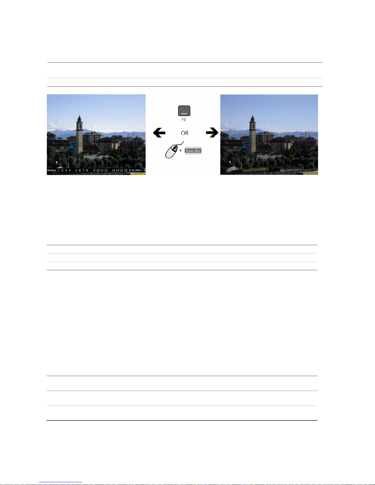
The status bar can be set to appear by default. See “Displaying the status bar” on page 43.
Page 30
24 TruVision DVR 40 User Manual
To activate/deactivate the on-screen status bar
Front panel/remote control Press the F2 button on the front panel to activate or deactivate the status bar.
Mouse Right-click the mouse and select Status Bar from the menu.
Selecting a monitor
The TVR 40 can be connected to up to two monitors. However, only one monitor can be
controlled at a time. You can select from which monitor to display the camera views in live mode.
To switch between monitors A and B
Front panel Press buttons A or B to switch between monitors A and B.
IR remote control Press buttons Mon A or Mon B to select between monitors A and B.
Mouse Right-click the mouse and select Swap Monitor from the menu shown.
Viewing in multiscreen
The 16-channel TruVision DVR 40 User Manual has five multiscreen display formats available
including full screen. The eight-channel TruVision DVR 40 User Manual has four multiscreen
display formats.
A cameo is any cell in a multiscreen display. A camera picture can only be shown in one cameo
at a time. To change the order of cameras in the cameos, see “To setup multiscreen and dwell
time” on page 46”.
T
o view a full screen display
Front panel Press the numeric button that corresponds to the camera number. For
example, press button 10 to preview camera number 10.
IR remote control Press two number buttons that corresponds to the camera number. For
example, press buttons 0 and 2 to preview camera number 02.
Mouse Right-click the mouse and select Camera from the menu shown. Select the
camera required.
Page 31

TruVision DVR 40 User Manual 25
To view a multiscreen display
Front panel/ IR remote
control
Press the Display button to switch to multiscreen live mode. If the multiscreen
display does not include all the cameras required, keep pressing the Display
button to increase the number of screens displayed.
Mouse Right-click the mouse and select Multi Screen from the menu. Select the
desired multiscreen display layout.
To manually cycle through live mode
Front panel/ IR remote
control
Press the Seq button to manually step through the live modes. You can set the
auto multiscreen mode in the Display menu. See section “Multiscreen and
sequ
encing” on page 46 for further information.
Mouse Use the mouse wheel to scroll forwards and backwards through the live
modes.
Manual recording
When a channel is recording, its corresponding camera LED on the front panel is green. This
recording status is also repeated in the Manual Record menu.
Manually start or stop a channel recording from the Manual Record menu. This menu is only
accessible using the mouse.
Page 32

26 TruVision DVR 40 User Manual
What the status options mean in the Manual Record menu
When the status of the camera number is:
• Green: Indicates the channel is recording
• Red: Indicates remote viewing
• Orange: Indicates both recording and remote viewing
• Grey: Indicates the channel is not recording
Start/Stop options:
• : Indicates recording is enabled
To manually start or stop a recording
1. Right-click the mouse and select the option Manual Record. Enter your user name and PIN,
if requested.
Note: You must have Record rights to change the manual recording status. See “Modifying
operational rights” on page 94 for mo
re information.
The Manual Record screen appears. All channels are listed. The Camera line shows the
channels that are currently recording. In the example below, 13 of the 16 channels are
recording.
2. On the Start/Stop line activate or deactivate a channel by press Enter or left-click the mouse
to activate () a channel that is not recording. Press or click again to de-activate.
The camera status LED on the front panel, and the camera number in the status bar on-
screen in live mode, turn green.
3. Select the next channel from which you want to start or stop recording.
4. If you want all channels to start recording, select Start All. All the channel status LEDs on the
front panel and the on-screen camera numbers in the status bar turn green.
Select Stop All to switch off all channels.
5. Press the Menu button on the front panel, or right-click the mouse, to save changes and
return to live mode.
Page 33

TruVision DVR 40 User Manual 27
Searching and playing back recorded video
The TVR 40 lets you quickly search and playback recorded video. You must be in live mode to
playback video. See Figure 13 below.
Figure 13: Playback screen
Note: You must have playback rights to playback recorded images. See “Modifying operational rights” on
page 94 for more information.
The system also lets you playback channels simultaneously so that multiple images appear onscreen.
Control playback progress
When in playback mode a status bar appears on-screen during playback to show playback
progress and speed. See Figure 14 below.
Figure 14: Playback status bar
Option Description
1. Audio Press PLAY to silence the audio recording associated with this video. Press
PLAY again to reactivate the audio.
Audio in this example is on.
2. Playback progress Shows how far you have progressed through the recorded file.
3. Playback speed Move the joystick left or right to change the rate of playback. Nine options are
available:
Single: Advance one frame at a time.
1/8x: An eighth of actual speed.
1/4x: Quarter of actual speed.
1/2x: Half of actual speed.
1x: Actual speed.
Page 34

28 TruVision DVR 40 User Manual
Option Description
2x: Twice actual speed.
4x: Four times actual speed.
8x: Eight times actual speed.
MAX: Maximum speed.
4. Current playback time Playback always starts from time zero. The actual time of the recording is
shown on the top of the screen.
Move the joystick up to jump forwards 30 seconds. It is not possible to jump
backwards.
5. Total playback time Shows the duration of the recorded file. In this example, it is 4 minutes 19
seconds.
6. Start/end copy Press the F1 button to start or stop copy a segment of the playback video.
If a mouse is connected to the unit, a toolbar appears that allows you to control many playback
functions with the mouse. See Figure 15 below.
Figure 15: Mouse playback toolbar
Item Description Icon Description
1. Jump back 30 seconds in the
playback video.
7. Start archiving the video.
2. Decrease the playback speed. See
Figure 14 for the list of speeds
available.
8 Remove the Playback toolbar. To make
it reappear on-screen, right-click the
mouse and select Display.
3. Pause playback. 9. Digital zoom. Double left-click the
mouse to zoom in. Double left-click
again to return to normal view.
4. Increase the playback speed. See
Figure 14 for the list of speeds
avail
able.
5. Jump forward 30 seconds in the
playback video.
10 &
11.
To view full screen when in multiscreen
mode, double-click the mouse on the
desired screen. It appears as full
screen.
Left-click the mouse on one of the icons
to move backwards or forwards through
the full screens.
6. Turn on or off audio. 12. Left-click the mouse to scroll through
the number of multiscreens displayed.
Search recorded video
There are many different ways to search recorded videos, such as:
Recordings which have alarms or motion detection, or have been manually recorded
Start and end time and date of recording
Text (from an ATM, for example)
Page 35

TruVision DVR 40 User Manual 29
To search for recorded video
1. In live mode press the Search button on the front panel of the TVR 40 or on the IR remote
control, or right-click the mouse and select Search. Enter your user name and PIN, if
requested.
The Playback menu appears.
2. In the Camera list box select the channel you want to search.
3. To select more than one camera for playback, click the Associated Setup box. In the
submenu that appears, select the cameras required.
4. In the Search for list box select the type of recorded videos to be searched.
Option Search for recorded file types
All All recordings
All Time Only scheduled time recorded files
Manual Only manually recorded files
Alarm Only alarm recorded files
Motion Det. Only motion detected files
5. For the Start and Stop recording periods go to each edit box and enter the start and end
dates and times as follows:
Front panel Press the joystick to enter the edit box. Move the joystick up or down to scroll
through the numbers to select a number. Move the joystick left or right to
move to the next edit box.
IR remote control Use the arrows buttons to change the numeric value. Press Enter when
completed and move to the next edit box.
Mouse Click the edit box and select the number required from the on-screen numeric
list that appears.
Note: Date has the format DD-MM-YYYY. Time has a 24-hour format. The default stop values
shown are the current time and date.
6. To search for video from a particular ATM, for example, enable () the Text check box.
Using the mouse, select the edit box alongside the check box to enter the text to be
searched (for example, text that appears on an ATM screen.) An on-screen alphanumeric
keyboard appears. Click Shift to select the type of character required: Number, upper case
Page 36

30 TruVision DVR 40 User Manual
letter, lower case, letter or symbol. There are 24 symbols to select. Press 0 on the front
panel to scroll between the four pages of symbols available.
Enter the text required.
7. Select Search to start the search.
When the search is completed a list of all the files found appears. The list may extend over
several pages. The most recent file is listed first.
Note: If you get a message saying that there are no recordings but you were expecting some to
be listed, check that you have selected the correct recorded file type option for your search.
8. Press the Live button or right-click the mouse to quit playback mode and return to live mode.
Playback recorded video
In the Playback screen there are three ways to playback a recorded file:
Playback only the selected file
Playback all the files listed in the search result:
Instant replay. The system will play the last five minutes recorded by the selected camera.
You must have playback rights to playback recorded images. See “Adding a new user” on page
93 for more information.
T
o playback a recorded file
1. Search for the files to playback. See “Search recorded video” on page 28 for further
information.
2.
Select the playback option required:
Only selected files: In the Search window select the video file required from the list
displayed. Press the joystick or left-click the mouse to enter playback mode. Only the
selected file will be played back.
All files: Select Play. The system will play each file listed, starting with the first file.
Instant playback: Select Instant Replay.
The unit enters playback mode. The playback status bar appears on-screen. If a mouse is
connected, the mouse playback toolbar also appears.
3. During playback mode, press Menu button or right-click the mouse to return to the Playback
menu. All the files selected for playback are now deselected.
4. Press the Live button or right-click the mouse to quit playback mode and return to live mode.
Page 37

TruVision DVR 40 User Manual 31
Archiving recorded files
Archive recorded files on an external device such as a USB. As well as being able to archive a
complete recorded file, you can also archive specific incidents in a file. You must be in live mode
to archive video. Access to archive functions may require a password.
There are three ways to archive a file:
Quick archive: Quickly archive all recorded files on the unit by pressing the Archive
button on the front panel or IR remote control.
Standard archive: Select the recorded files that you want to archive.
Auto backup: Recordings are automatically backed up according to a set schedule.
You must have playback rights to playback recorded images. See “Adding a new user” on page
93 for more information.
Files can
be saved on several types of media. If both a DVD/CD and a USB device are found in
the TVR 40, the DVD/CD takes precedence.
Note: Avoid moving the external recording device when backing up information onto it.
Quick archive
To quickly archive all recorded files
1. Insert the backup device into the TVR 40.
2. Go to the Media edit box and select the backup device required.
3. In live mode press the Archive button on the front panel of the TVR 40 or on the IR remote
control, or right-click on the mouse and select Archive. Enter your user name and PIN, if
requested. The Playback screen appears.
The last 24 hours of videos recorded on the unit are listed.
4. Press Archive button again to immediately start downloading the video files on to the
selected media. A message appears when copying is completed.
Note: Press the Menu button to abort the archive and return to live mode.
Manually select files to archive
You can archive specific incidents from a recorded video. When playback is stopped, they are
saved automatically onto the selected archive medium. Incidents can be saved until the archive
medium is full.
Note: Avoid moving the external recording device when backing up information onto it.
Page 38

32 TruVision DVR 40 User Manual
To archive recorded files found in a search
1. Insert the backup device into the TVR 40.
2. Press the Search button on the front panel or IR remote control, or right-click the mouse and
select Search. Enter your user name and PIN, if requested. The Playback screen appears.
The last two hours of videos recorded on the unit are listed.
3. Search for the recorded files you want to copy. See “Search recorded video” on page 28.
The most recent file
is listed first.
4. To select all the video files listed, press the F2 button on the front panel or IR remote control.
All files will be highlighted. To deselect all the files, press F2 again.
To select a specific file, highlight the file required in the window and press the F1 button on
the front panel or IR remote control.
5. Go to the Media edit box and select the required archive medium.
6. Go to Start and press Enter or left-click the mouse to write the files to the archive medium. A
message appears when copying is completed. Press OK.
7. Press Menu or right-click the mouse to quit playback mode and return to live mode.
To archive specific incidents in a recorded file
1. Insert the backup device into the TVR 40.
2. Press the Search button on the front panel or IR remote control, or right-click the mouse and
select Search. Enter your user name and PIN, if requested. The Playback screen appears.
The last two hours of videos recorded on the unit are listed.
3. Search for the recorded files you want to copy. See “Search recorded video” on page 28.
The most recent file
is listed first.
4. Go to Media and select the desired medium on which to copy the file.
5. Select the video file(s) in the search results list that you want to archive. Selected files are
highlighted.
If using the front panel or remote control, press F1 and select the file you want. Press Enter
to start playback.
If using the mouse, double-click the file you want. Playback starts.
The Playback toolbar will show the archiving progress of the selected file.
6. When you reach the part of the playback that you want to copy, press F1 to start copying. A
red radio button appears in the right hand corner of the screen when copying is taking place.
Press F1 again to stop copying. The red radio button disappears. You can copy several
sections of the same playback file.
7. If using the mouse, adjust the playback variables as required. See “Control playback
progress” on page 27 for the description of the icons. Playback can also be paused by
pressing Ent
er, and then pressing it again to restart it.
Page 39

TruVision DVR 40 User Manual 33
8. When finished copying this recording, press Menu or right-click the mouse to exit. A
message appears asking you to confirm that you want to copy the file. Select OK.
9. Press Menu or right-click the mouse to quit playback mode and return to live mode.
Automatically backup recorded files
You can automatically backup recordings according to a set schedule. For example, at the end
of every day all recordings from all cameras are automatically backed up.
Backups are done to an external hard drive.
To backup recorded files
1. Connect the external hard drive to the TVR 40.
1. In live mode press the Search button on the front panel or IR remote control, or right-click the
mouse and select Search. Enter your user name and PIN, if requested. The Playback screen
appears.
2. Go to the Media edit box and select the option eSATA HDD on which to do the auto backup.
Note: To be able to record video on a DVR-eSATA-DVD drive ensure that the eSATA option in
the Recording menu has been set Record. See “Recording settings” on page 63 for more
information.
3. Go to Backup and press the joystick or left-click the mouse to select. The Backup submenu
appears.
4. The first time you use the external hard drive, go to the e-Sata Free Space Format button
and press Enter or left-click the mouse to format the external drive.
5. Go to the Auto Archive check box and press the joystick or left-click the mouse to enable
Auto Archive, if required.
6. Go to the Camera list box and select the camera whose recordings are to be archived and
enable the check box beside the camera number box. Do this for each camera to be
included in the backup.
Page 40

34 TruVision DVR 40 User Manual
7. Go to the Archive Today list box to set the number of days back to be automatically archived.
Up to 6 days can be selected. Today is 0. Yesterday is -1.
8. Go to the Set Today’s Time edit boxes and enter the period of time during the day to be
archived.
Note: Time has a 24-hour format.
9. Go to the Archiving Delay list box and select the time after activating the TVR 40 for auto
backup to start. If the option “0Min” is selected, backup will start immediately OK is pressed.
10. Select OK to save your changes and return to live mode.
Controlling a PTZ camera
You can control the PTZ operation of the cameras. It is entered from live mode.
The PTZ camera can be controlled using buttons on the front panel and IR remote control as
well using the on-screen PTZ control icons accessed with the mouse. However, some functions
are only available using the mouse.
See Figure 16 below for the on-screen PTZ control icons accessed using the mouse.
Figure 16: Mouse PTZ control icons
The autopan function is only available using the mouse. This function is the automatic back and
forth movement of a camera. The function depends on the camera used.
Access to PTZ functions may require a PIN.
To enter PTZ mode
1. In live mode press the joystick on the front panel or OK on the IR remote control, or right-
click on the mouse, and select PTZ Control.
2. Move the camera as required. See Table 4 on page 35 for the descriptions on how to control
PTZ using t
he front panel, IR remote control and mouse.
Page 41

TruVision DVR 40 User Manual 35
Table 4: Controlling PTZ
Control
Front panel
IR remote
control
Mouse on-screen
icons
Description
Move joystick
up/down and
left/right.
Press the arrow
buttons.
Pan left/right and tilt up/down.
Press the Zoom+
and Zoombuttons.
Press Zoom+
and Zoombuttons.
Zoom in (+) and out (-).
Not available Press Focus+
and Focusbuttons.
Focus in (+) and out (-).
Not available Not available
Open (+) and close (-) the iris control.
Press the Preset
button
Press the Preset
button.
Right-click the
mouse and select
the Preset menu
command.
Call up a pre-programmed preset. See below for
further instructions.
Press the Tour
button
Press the Tour
button.
Right-click the
mouse and select
the Tour menu
command.
Call up a pre-programmed Shadow tour. See
below for further instructions.
Not available Not available
Call up a pre-programmed autopan. See below
for further instructions.
3. To quit PTZ mode press the Menu button on the front panel or the OK button on the IR
remote control, or right-click on the mouse and select Exit.
To call up a PTZ preset number
1. In PTZ mode, do one of the following:
Front panel Press the Preset button. Enter a preprogrammed three-digit preset number.
Preset starts immediately.
Remote control Press the Preset button. Enter a preprogrammed three-digit preset number.
Preset starts immediately.
Mouse Right-click the mouse and select the menu option Preset. Select one of the
preset numbers listed.
Note: The PTZ preset number is preprogrammed. See section “PTZ settings” on page 86 for
further information.
The TVR 40 will adjust to the settings of this preset number.
2. If you want to use a different preset PTZ number, repeat step 1 when in the PTZ mode. The
unit will re-adjust to that preset number.
3. To exit PTZ mode press the Menu button on the front panel or the OK button on the IR
remote control, or right-click the mouse and select Exit. You will return to live mode and the
camera will stay in its current position.
Page 42

36 TruVision DVR 40 User Manual
To call up a PTZ shadow tour number
1. In PTZ mode, do one of the following:
Front panel Press the Tour button. Enter a preprogrammed three-digit preset number.
Shadow tour starts immediately.
Remote control Press the Tour button. Enter a preprogrammed three-digit preset number.
Shadow tour starts immediately.
Mouse Right-click the mouse and select the menu option Tour. Select one of the tour
numbers listed.
Note: The PTZ preset number is preprogrammed. See section “PTZ settings” on page 86 for
further information.
The TVR 40 will adjust to the settings of this shadow tour number.
2. If you want to use a different shadow tour PTZ number, repeat step 1 when in the PTZ mode.
The unit will re-adjust to that shadow tour number.
3. To exit PTZ mode press the Menu button on the front panel or the OK button on the IR
remote control, or right-click the mouse and select Exit. You will return to live mode and the
camera will stay in its current position.
To start/stop autopan
Note: This function is only available when using the mouse.
1. In live mode right-click the mouse and select PTZ control to enter PTZ mode. Click the
Autopan icon
to start the panning.
Note: If the PTZ is in autopan mode and you exit PTZ mode, PTZ will continue in autopan
mode. You must re-enter PTZ mode to stop the autopan.
2. To exit PTZ mode, right-click the mouse and select Exit. You will return to live mode and the
camera will stay in its current position.
Manually acknowledging an alarm
When an alarm is triggered, the alarm indicator on the front of the TVR 40 flashes red to alert
you to the alarm. The alarm can be manually acknowledged to silence it. However, the alarm will
still be active.
This option can only be done when the alarm output is set to Acknowledge. See “External alarm
output” on page 82 for further information.
All alarm acknowledgements are saved in the system log.
T
o manually acknowledge an alarm
1. When the alarm indicator on the front panel is flashing red, press the manual alarm button to
acknowledge the alarm. The red flashing light will return to green.
The LED of the alarm source (for example, camera or system status) will continue to display
red.
Page 43

TruVision DVR 40 User Manual 37
Overview of the menu structure
The TVR 40 has an icon driven menu structure that allows you to configure the unit’s
parameters. Figure 17 below shows the TVR 40 main menu screen. Each icon symbolizes the
content of th
e submenu. The menu icon selected has a white action frame around it.
Many of the submenus are only available to privileged users, such as the system administrator.
You must be in live mode to access the menu mode where you can setup or change the TVR 40
settings in menu mode.
Figure 17: The TVR 40 main menu
Action frame
Table 5: Description of the eight menu icons
Menu icon Description
Display Configure the bus address, login PIN request, menu timeout, video standard, VGA, time
and date, and multiscreen.
See “Display settings” on page 41.
Cameras Configure the camera titles, video adjustment, advanced camera settings, time and date
position, and motion detection.
See “Camera settings” on page 49.
Recording Configure the recording mode, e-SATA, image resolution, recording rates, bits rates, and
pre and post recording settings.
See “Recording settings” on page 63.
Network Configure the standard network settings, e-mail, and advanced network settings.
See “Network settings” on page 71.
Alarms Configure the alarm input type, alarm rules, alarm output type, PTZ linkage, notification
settings.
See “Alarm settings” on page 79.
PTZ Configure the RS-485, PTZ protocols, and PTZ addresses. Comprehensive configuration
of UTC domes, and basic setup of non-UTC devices.
See “PTZ settings” on page 85.
User Configure user rights.
See “User settings” on page 91.
System Configure the RS-232. Manage firmware upgrade, and HHD. View log and system view.
Acknowledge alarms, reboot the DVR, and power off.
See “System settings” on page 97
Page 44

38 TruVision DVR 40 User Manual
To access a menu
1. Press the Menu button on the front panel of the TVR 40 or on the IR remote control, or right-
click the mouse and select Menu. Enter your name and PIN, if requested. The main menu
appears.
Note: The factory default Administrator name is “admin“ and the PIN is “1234“.
2. Using the joystick, IR remote control, or the mouse, select the menu icon required.
3. Press the joystick, press the OK button on the IR remote control, or left-click the mouse to
enter the selected menu. The selected menu screen appears. An example is shown below:
4. When all changes to menu options have been done, go to OK. Press the joystick, press OK
on the IR remote control, or left-click the mouse to save the changes and return to the main
menu screen.
To abort all changes select Cancel.
Note: Selecting OK in submenus confirms but does not save the changes made. Changes are
only saved when OK is selected in the main menu.
5. Press the Live button on the front panel or the IR remote control, or right-click the mouse, to
exit the main menu and return to live mode.
Navigating through a menu screen
The TVR 40 is delivered with default settings that can be easily changed from the menus.
You can use the mouse, front panel buttons, or the IR remote control to change settings.
Mouse: Use the mouse to select any option or button on the screen.
Front panel: Move the trigger-point joystick on the front panel up, down, left, and right to
navigate through the options and press the joystick for Enter to select. Press the Menu button to
return to the configuration category and the main menu.
IR remote control: Press the arrow buttons on the IR remote control to navigate through the
options and press OK to select. Press the Menu button to return to the configuration category
and the main menu.
Page 45

TruVision DVR 40 User Manual 39
Caution: If there is a power failure during setup, you will loose all user-modified settings. The
system will return to the programmed settings.
Changes to screen settings can be entered in various ways as shown in Table 6 below.
Table 6: Types of control
Control Function Description
Check box
Select either enable (
) or disable (empty).
Press the joystick to toggle between them or left-click
the mouse.
List box Select one of the listed options.
Front panel: Move the joystick up or down to select
an option. Press the joystick to accept changes made
in the list box.
IR remote control: Press the up or down arrows to
select an option. Press OK to accept changes made
in the list box.
Mouse: Position the mouse cursor on the list box
arrows and left-click the mouse to scroll through the
options.
Edit box An edit box lets you type characters to set the value
of an option. Click the box and an on-screen keyboard
will appear. Depending on the type of information
required, the on-screen keyboard will be numeric or
alphanumeric.
This function can only be done using the mouse.
Left-click the mouse. A numeric or alphanumeric onscreen display appears. Select the characters
required. When completed, left-click the mouse on the
menu screen to accept changes.
Setup button Execute a function or enter into the next submenu.
A setup button is inactive (grey) until its parameter
option is enabled.
Turning off the TVR 40
Turn off the power switch located on the back of the unit.
Page 46

40 TruVision DVR 40 User Manual
Page 47

TruVision DVR 40 User Manual 41
Display settings
Use the Display menu to configure which information is displayed on-screen and how it should
look. The following options can be configured:
The language of the unit
The device ID
If a PIN is required
If the status bar appears on-screen
The menu timeout
The video output standard
The video scaling
The menu transparency
The VGA interface
The brightness of the screen
The system time and date
The multiscreen format
Daylight Saving Time (DST)
The dwell time and alarm dwell time
The Display menu icon
is located in the main menu. The following menu appears when you
select the Display icon:
Page 48

42 TruVision DVR 40 User Manual
Figure 18: The Display setup menu
The following procedures show how to change the monitor display settings from the Display
menu. They can be changed in any order.
Selecting a language
To select a language
1. In the Display menu go to Language and do one of the following:
Front panel: Select the list box. Press the joystick for Enter. Move the joystick up or down to
scroll through the languages. Press the joystick to select a language.
IR remote control: Use the IR remote control arrow buttons to select the list box and press
OK. Use the up/down arrows to scroll through the language and press OK to select a
language.
Mouse: Left-click the mouse to select the required language. The language on screen
changes immediately.
The default language is English.
Note: The last language used on the TVR 40 will be the unit’s language when the system is
rebooted.
2. When you have made all the changes required in the Display menu, go to OK and press
Enter or left-click the mouse to save all changes and return to the main menu. Press the
Menu button to return to live mode.
Page 49

TruVision DVR 40 User Manual 43
Setting the device ID
When you use the IR remote control to operate the TVR 40, the TVR 40 must have a device ID.
The default device ID is “01“. If there is more than one DVR used, each unit must have its own
unique device ID as otherwise the IR remote control will control all the units together.
To set the TVR 40’s device ID
Front panel or remote
control
In the Display menu go to the Bus Address edit box and press F1. Using
the number buttons, enter the number of the device ID.
Mouse In the Display menu go to the Bus Address edit box and left-click the
mouse. Select the number from the on-screen numeric display.
When you have made all the changes required in the Display menu, go to OK and press
Enter or left-click the mouse to save all changes and return to the main menu. Press the
Menu button to return to live mode.
Setting the PIN requirement
A PIN is required by default to access the TVR 40. See “Modifying a user’s PIN” on page 93 for
information on PINs.
To setup the PIN requirement
1. In the Display menu go to the Log In PIN Required check box and press Enter or left-click
the mouse to enable () or disable it
2. When you have made all the changes required in the Display menu, go to OK and press
Enter or left-click the mouse to save all changes and return to the main menu. Press the
Menu button to return to live mode.
Displaying the status bar
The status bar appears on-screen by default.
To display the status bar
1. In the Display menu go to the Status Bar check box and press the joystick or left-click the
mouse to enable () or disable it.
2. When you have made all the changes required in the Display menu, go to OK and press
Enter or left-click the mouse to save all changes and return to the main menu. Press the
Menu button to return to live mode.
Page 50

44 TruVision DVR 40 User Manual
Menu timeout
This is the time after which the selected menu screen reverts to the live mode.
To setup the menu timeout
1. In the Display menu go to the Menu Timeout list box and press Enter or left-click the mouse.
Select the time.
2. When you have made all the changes required in the Display menu, go to OK and press
Enter or left-click the mouse to save all changes and return to the main menu. Press the
Menu button to return to live mode.
Selecting video standard
The TVR 40 can support PAL or NTSC video output. PAL is the default format.
To select the video standard
1. In the Display menu go to the Video Standard list box and press Enter or left-click the
mouse. Select either NTSC or PAL video output format.
Note: If you are using default settings but the images on screen flicker, there is a NSTC/PAL
mismatch. Check the NTSC/PAL option selected in the Display menu.
2. When you have made all the changes required in the Display menu, go to OK and press
Enter or left-click the mouse to save all changes and return to the main menu. Press the
Menu button to return to live mode.
Video scaling
You can change the settings of the monitor display size to accommodate for differently sized
monitors.
To adjust the screen scaling
1. In the Display menu go to the Video Scaler and press Enter or left-click the mouse to enable
the check box () .
When disabled, the video output display resolution is 704 x 576 PAL (or 704 x 480 NTSC).
When activated the display resolution becomes 640 x 576 PAL (or 640 x 480 NTSC).
2. When you have made all the changes required in the Display menu, go to OK and press
Enter or left-click the mouse to save all changes and return to the main menu. Press the
Menu button to return to live mode.
Page 51

TruVision DVR 40 User Manual 45
Menu transparency
You can modify the transparency of menu items on screen relative to the background to make
the on-screen text easier to read.
To change the menu transparency
1. In the Display menu go to the Menu Transparency list box and press Enter or left-click the
mouse. Select the transparency level. The screen transparency changes as you scroll
through the list of options.
2. When you have made all the changes required in the Display menu, go to OK and press
Enter or left-click the mouse to save all changes and return to the main menu. Press the
Menu button to return to live mode.
Defining VGA resolution
You can define the VGA resolution and refresh frequency.
To setup the VGA interface
1. In the Display menu go to the Menu Transparency list box and press Enter or left-click the
mouse. Select one of the options available:
1280*1024@60 Hz
1024*768@60 Hz (default)
800*600@60 Hz
2. When you have made all the changes required in the Display menu, go to OK and press
Enter or left-click the mouse to save all changes and return to the main menu. Press the
Menu button to return to live mode.
Setting system time and date
You can setup the TVR 40 date and time as well as the Daylight Saving Time (DST). This is the
date and time that will appear on screen.
You can setup when DST for the TVR 40 starts and stops in the year. It is deactivated by
default.
To set the system time and date
1. In the Display menu go to the Time & Date setup button and press Enter or left-click the
mouse. The Time & Date submenu appears.
2. Go to the Date Format list box. Press Enter to select the list box and then move the joystick
up or down to scroll through the options. Press Enter again to select the required option. If
using the mouse, left-click the mouse to select the date format.
3. Go to the Date edit box. The default date format is dd-mm-yyyy. Do one the following:
Page 52

46 TruVision DVR 40 User Manual
Front panel: Press Enter to enter edit mode. Move the joystick up or down to scroll through
the numbers in the date box. Press the joystick again to exit edit mode. Repeat for each date
box.
Mouse: Left-click the mouse to enter edit mode. An on-screen numeric keyboard appears.
Click the date numbers required. Left-click the mouse again to exit edit mode. Repeat for
each date box.
4. Go to the Time edit box. The time is 24-hour format (hh-mm-ss). Do one the following:
Front panel: Press Enter to enter edit mode. Move the joystick up or down to scroll through
the numbers in the time box. Press the joystick again to exit edit mode. Repeat for each time
box.
Mouse: Left-click the mouse to enter edit mode. An on-screen numeric keyboard appears.
Click the time numbers required. Left-click the mouse again to exit edit mode. Repeat for
each time box.
5. Go to the Enable Daylight Savings check box and press Enter or left-click the mouse to
enable (). Once enabled, the dates become active.
6. Select the month and day when Daylight Savings starts and stops.
7. Go to OK and press the joystick or left-click the mouse to confirm the changes and return to
the Display menu.
8. When you have made all the changes required in the Display menu, go to OK and press
Enter or left-click the mouse to save all changes and return to the main menu. Press the
Menu button to return to live mode.
Multiscreen and sequencing
This submenu allows you to set up how many camera cameos appear on-screen by default as
well the dwell time for a sequence.
To setup multiscreen and dwell time
1. In the Display menu go to Multi Screen setup button and press Enter or left-click the mouse.
The Multi Screen menu appears.
Page 53

TruVision DVR 40 User Manual 47
2. Go to the Monitor Output list box. Select between monitor output A or B. Monitor A is default.
3. Go to the Display list box. Select the desired multiscreen mode from the drop-down list.
Press Enter to select the list box and then move it up or down to scroll through the options.
Press Enter again to select the required option. If using the mouse, left-click the mouse to
scroll through the display formats. See Table 7 below for the options available.
Table 7: Multi screen options available
Number of TVR 40 channels Multi screen options
4 Full
4 way
8 Full
4 way
8 way
16 Full
4 way
9 way
12 way
16 way
4. Go to the Dwell Time list box. The dwell time is the amount of time the unit stays on an
individual camera before moving onto the next one in a sequence.
Select the desired dwell time from the drop-down list. Press Enter to select the list box and
then move it up or down to scroll through the options. Press Enter again to select the
required option. If using the mouse, left-click the mouse to scroll through the display formats.
See Table 8 on page 48 for the options available.
Page 54

48 TruVision DVR 40 User Manual
Table 8: List of dwell time options
Options Description
Off The live display will not automatically switch.
5S The live display will automatically switch after 5 seconds.
10S The live display will automatically switch after 10 seconds.
20S The live display will automatically switch after 20 seconds.
30S The live display will automatically switch after 30 seconds.
For example: If a 16-channel TVR 40 has the 4-screen live mode and the 20-second dwell
time selected, the TVR 40 will cycle four camera displays every 20 seconds.
5. Go to the Audio check box. You can select to hear and record audio from the selected
camera. Press Enter or left-click the mouse to enable () or disable audio.
6. Go to Alarm Aux Out to select which monitor should work as an alarm spot monitor. If there
is an alarm, the video will pop up on this monitor.
7. Go to the Alarm Dwell Time edit box. This is the time delay before the alarm video appears
on screen. If there is more than one alarm, there is also the delay switching between the
alarm videos. Select the time delay required: Off, 3, 4, 5, or 10 seconds.
8. Go to Display Layout. Select the sequence in which the cameras will be displayed in the
main monitor. Cameras are sequenced in numeric order by default. Each numbered square
on-screen corresponds to that numbered camera. Press the number button that
corresponds to the camera you want displayed first. Continue for each camera. The
sequence order is displayed in the bar underneath.
9. When complete, go to OK and press Enter or left-click the mouse to accept all the changes
and return to the Display menu.
10. When you have made all the changes required in the Display menu, go to OK and press
Enter or left-click the mouse to save all changes and return to the main menu. Press the
Menu button to return to live mode.
Page 55

TruVision DVR 40 User Manual 49
Camera settings
Use the Camera menu to configure the cameras. The following options can be configured:
The name of each camera
The position of the camera name on screen
The camera brightness, contrast, saturation and hue
The display properties of each camera (OSD)
The area on screen to be masked
When to view a tamper alarm
The video loss alarm
The motion detection alarm
The Camera icon
is located in the main menu. The following menu appears when you
select the Camera icon:
Figure 19: The Camera menu
Page 56

50 TruVision DVR 40 User Manual
The following procedures show how to change camera settings from the Camera menu. They
can be changed in any order.
All changes made to the Camera menu apply to the selected camera. The camera settings of
one camera can easily be copied to another camera.
Setting up the camera title
Each camera can be given a title, which must be unique. If you do not give a camera a title, it is
automatically pre-numbered.
To setup the camera title
1. In the Camera menu go to the Camera list box and press Enter or left-click the mouse.
Select the number of the camera you want to name.
2. Go to the Title edit box and press Enter or left-click the mouse to enter into edit mode.
3. Enter the camera title. Left-click the mouse to enter edit mode. An alphanumeric on-screen
display appears. Select the characters required. Default is a number. Click Shift to select the
type of required character (upper or lower case letters, or special characters.) The character
type is shown on the bottom of the screen.
Note: This edit function can only be done using the mouse.
4. Left-click the mouse to exit edit mode.
5. When you have made all the changes required in the Camera menu, go to OK and press
Enter or left-click the mouse to save all changes and return to the main menu. Press the
Menu button to return to live mode.
Positioning the camera title
You can position the camera title anywhere on the screen.
To position the camera title on screen
1. In the Camera menu enable the Title Position check box () if you want the camera title to
appear on-screen. When enabled, the Position setup button alongside it becomes active.
2. Go to the Position setup button and press Enter, or left-click the mouse, to enter into edit
mode. A grid appears on-screen with the camera title in the bottom right corner of the
screen.
3. Move the joystick up/down/left/right to move the camera title around the screen. When you
are satisfied with the position, press Enter again or left-click the mouse to confirm and return
to the Camera menu.
Instructions on how to position the camera title are also provided on-screen.
Page 57

TruVision DVR 40 User Manual 51
4. When you have made all the changes required in the Camera menu, go to OK and press
Enter or left-click the mouse to save all changes and return to the main menu. Press the
Menu button to return to live mode.
Modifying the image quality
Different cameras and backgrounds may need to have the screen image modified in order to
obtain the best video image. Use this menu to configure the video image. You can setup each
camera separately or copy the video parameters of one camera to another camera.
To modify the image quality of the camera video
1. In the Camera menu select the camera you want to adjust. Go to the Adjust Video setup
button and press t Enter, or left-click the mouse. The Adjust Video menu appears.
2. Go to the Brightness setup button and press Enter, or left-click the mouse. A scroll bar
appears at the bottom of the screen.
3. Use the up/down arrow buttons to adjust the brightness level. The video camera changes at
the same time.
4. When you are satisfied with the real time video of the camera, press Enter, or left-click the
mouse.
5. Repeat steps 2 to 4 for the Contrast settings of this camera.
6. When completed, select OK and return to the Camera menu.
7. When you have made all the changes required in the Camera menu, go to OK and press
Enter or left-click the mouse to save all changes and return to the main menu. Press the
Menu button to return to live mode.
Page 58

52 TruVision DVR 40 User Manual
Displaying the current time and date on-screen
Select the format of the current date and time displayed on-screen, as well as where it appears.
To setup a camera’s displayed time and date
1. In the Camera menu select the camera you want to adjust.
2. Go to the Time & Date list box and press Enter or left-click the mouse to select the display
mode required.
Solid The text contrast automatically adjusts relative to the background.
Transparent The screen image appears through the text.
Not Displayed Nothing is displayed (Default).
3. Press Enter or left-click the mouse to confirm the entry.
4. Go to the Position setup button and press Enter or left-click the mouse. A grey screen with
the date/time bar in white appears.
5. Press F1 if using the front panel, press the Analog button on the IR remote control, or rightclick the mouse and select Format, to select one of the formats displayed:
YYYY-MM-DD, Day of the week, 24-hour time
YYYY-MM-DD, 24-hour time
MM-DD-YYYY, Day of the week, 24-hour time
MM-DD-YYYY, 24-hour time
DD-MM-YYYY, Day of the week, 24-hour time
DD-MM-YYYY, 24-hour time
Instructions on how to position the time and date are also provided on-screen.
6. Using the arrow buttons move the date/time bar around the screen. When satisfied with the
position press Enter, or right-click the mouse and select OK, to return to the Camera menu.
Page 59

TruVision DVR 40 User Manual 53
7. When you have made all the changes required in the Camera menu, go to OK and press
Enter or left-click the mouse to save all changes and return to the main menu. Press the
Menu button to return to live mode.
Motion detection
The TVR 40 can be setup to trigger an alarm if a camera detects motion. Select the level of
sensitivity to motion as well as the target size so that only objects that could be of interest can
trigger a motion recording. For example, the motion recording is triggered by the movement of a
person but not that of a cat.
Mask out any areas of motion on-screen that you do not want to trigger recording such as a flag
on a pole or a moving tree.
Figure 20: Example of motion detection setup screen
1. White square to mark out new activated motion detection zone
2. Existing motion detection zone
3. Area not selected for motion detection
To setup the TVR 40 to respond to a motion detection alarm
1. To set the motion detection sensitivity level
In the Camera menu go to the Motion Detection list box and select the desired motion
detection sensitivity level required.
There are seven levels to choose from: 0 (lowest) to 6 (highest) as well as “Off”. If “Off” is
selected, the unit will not respond to any motion detection. If 0 to 6 is selected, motion
detection Zone and Rules setup buttons become active. Press Enter on the front panel or IR
remote control, or left-click the mouse, to confirm the change.
Page 60

54 TruVision DVR 40 User Manual
2. To select the motion detection zone(s)
a. Go to the Zone setup button and press Enter or left-click the mouse. The Motion Zone
setup screen appears.
There is a solid white pane on-screen. The motion zone setup steps are the same as
those for mask zone setup (see page 57).
b. Front panel/IR remote control: Use the following buttons t
o setup the motion zones:
Front panel
buttons
IR remote
control buttons
Action
, , , , , ,
Move the white pane to any position
F1 Analog
Toggle between the white (deactivate) and grey (activate) panes
When the square is grey (activated) increase the size of the
transparent zone when moved left to right
When the square is grey (activated) decrease the size of the
transparent zone from the right to left
When the square is grey (activated) increase the size of the
transparent zone from up to down
When the square is grey (activated) decrease the size of the
transparent zone from down to up
F2 IP
Select the whole screen as a motion zone
F2 IP
Clear all motion zones
Enter OK
Save changes and return to the Camera menu
Menu Menu
Cancel setup and return to the Camera menu
Move the white square to the area on-screen that you want to mark as a motion detection
zone. Press F1. The square becomes transparent. This shows the selected square is
activated and will detect motion.
Use the arrow buttons or drag the square with the mouse cursor in a left-to-right or up-to-
down direction to extend the transparent square. When you have finished marking out
the transparent zone to be masked, press Enter to exit and return to the solid white
square to continue masking.
Mouse: Position the mouse cursor at the top of the zone to be activated for motion
detection. Drag the cursor in a left-to-right or up-to-down direction to extend the
transparent square.
c. Repeat step b for each zone on-screen where you want to detect motion. An example of
motion detection zones is shown below.
Page 61

TruVision DVR 40 User Manual 55
d. To clear part of a motion detection zone:
Front panel/IR remote control: Move the solid white square to the top of the motion
detection zone to be deleted. Press the F1/Analog button. The white pane becomes
transparent. Use the arrow buttons in a left-to-right or up-to-down direction to mark the
squares in the motion zone to be kept. Once the zone to be deleted is marked in a white
square, use the arrow buttons in a right-to-left or down-to-up direction to over-write the
selected area. The marked squares become transparent and are no longer selected as a
motion detection zone.
Mouse: Drag the mouse cursor in a left-to-right or up-to-down direction over the
activated motion detection zone. The activated squares are deactivated.
To clear all motion detection zones, press the F2 button.
e. Press Enter, or right-click the mouse and select OK, to confirm changes and to return to
the Camera menu.
3. To setup the response rules to a motion alarm
a. Go to the Rules setup button and press Enter on the front panel or left-click the mouse.
The Rules menu appears.
Page 62

56 TruVision DVR 40 User Manual
b. Go to the Record Camera check boxes and select the cameras from which you want to
be able to record a motion alarm. Press Enter, or left-click the mouse, to enable the
option. Press or click again to disable.
Note: For the cameras to be able to record a motion alarm, they must first be setup for
motion recording. This is done in the Recording menu. See“Setting up a camera’s
recording s
chedule” on page 68 for more informa
tion.
c. Go to Alarm Schedule and select when you want the TVR 40 to respond to a motion
alarm. You can select up to seven days in a week and up to four time periods for each a
day.
Note: The four daily time periods cannot overlap.
d. Go to the notification options and press Enter or left-click the mouse to enable () or
disable how you want the TVR 40 to respond to a motion alarm during live mode.
Table 9: Notification options on how to respond to a camera tamper alarm
Notification option Description
Alarm Out Alarm Out is activated. Up to four alarm outputs can be enabled.
Buzzer An audible alarm sounds
TCP Alarm information is sent to the remote IP (see “Advanced IP settings”
on page 74for more inform
ation)
Full Screen The alarm channel will be displayed on screen
Email Alarm information is sent to an e-mail address (see “E-mail settings” on
page 73 for more information)
The TVR 40 returns to live mode when there is no longer a motion alarm.
Page 63

TruVision DVR 40 User Manual 57
e. If you want to copy the periods from one camera to another, go to the Copy to list box
and select which day you want to copy to and then select Copy.
4. Select OK to confirm the changes and to return to the Camera menu.
5. When you have made all the changes required in the Camera menu, go to OK and press
Enter or left-click the mouse to save all changes and return to the main menu. Press the
Menu button to return to live mode.
Privacy masks
You can mask a sensitive area on screen so that it remains hidden from view. An example would
be when the view of a camera overlooks onto residential premises. The area hidden by the
privacy mask will not be viewed live nor recorded but will appear as a blank area on screen.
To setup a privacy mask
1. In the Camera menu go to Advanced Settings setup box and press Enter or left-click the
mouse. The Advanced Settings submenu appears.
2. Go to the Privacy Masking check box and press Enter or left-click the mouse to enable ().
The Zone option is activated. Privacy masking is disabled by default.
Note: No masked zone appears on-screen when Privacy Mask is disabled.
3. Go to the Zone button and press Enter or left-click the mouse.
The matrix screen appears. For PAL there are 22 x 18 panes in the matrix. In the top left-
hand corner of the matrix there is a white pane.
Page 64

58 TruVision DVR 40 User Manual
4. Front panel/IR remote control: Use the following buttons to setup the mask zones:
Front panel
buttons
IR remote
control buttons
Action
, , , , , ,
Move the white pane to any position
F1 Analog
Toggle between the white (deactivate) and grey (activate) panes
When the square is grey (activated) increase the size of the
transparent zone when moved left to right
When the square is grey (activated) decrease the size of the
transparent zone from the right to left
When the square is grey (activated) increase the size of the
transparent zone from up to down
When the square is grey (activated) decrease the size of the
transparent zone from down to up
F2 IP
Select the whole screen as a motion zone
F2 IP
Clear all motion zones
Enter OK
Save changes and return to the Camera menu
Menu Menu
Cancel setup and return to the Camera menu
Move the white square to the area on-screen that you want to mark as a mask zone.
Press F1. The square becomes transparent. This shows the selected square is masked.
Use the arrow buttons or drag the square with the mouse cursor in a left-to-right or up-to-
down direction to extend the transparent square. When you have finished marking out
the transparent zone to be masked, press Enter to exit and return to the solid white
square to continue masking.
Mouse: Position the mouse cursor at the top of the zone to be activated for masking.
Drag the cursor in a left-to-right or up-to-down direction to extend the transparent square.
5. Repeat step 4 for each zone on-screen that you want to mask.
There can be up to four masked zones in a screen. The maximum size of a masked zone is
8 x 8 panes. The minimum size is one pane.
6. Press Enter to return to the advanced settings submenu.
Note: The changes have not yet been saved. Changes are only saved when OK is selected in
the Camera menu screen.
7. Repeat steps 1 to 6 for the other cameras that require masking.
Page 65

TruVision DVR 40 User Manual 59
8. In the Advanced Settings submenu press OK to return to the Camera menu.
9. When you have made all the changes required in the Camera menu, go to OK and press
Enter or left-click the mouse to save all changes and return to the main menu. Press the
Menu button to return to live mode.
Viewing a camera tamper alarm
You can setup the system to alert you when someone has deliberately blocked a camera view,
such as by spraying paint on the lens (also known as anti-masking). You can set it up so that a
specific part of the screen can detect a tamper and thereby trigger an alarm. You can also setup
how the system will alert you to the tamper alarm. You can only setup one anti-masking area on
screen.
To setup the viewing of a camera tamper alarm
1. In the Camera menu go to Advanced Settings setup button and press Enter or left-click the
mouse. The Advanced Settings submenu appears.
2. To set the detection sensitivity level to a camera tamper alarm
Go to the Camera Tampering list box. Select the sensitivity level required. The options are:
Off
Low
Normal (default)
High
When Low, Normal, or High are selected, the Zone and Rules setup boxes become active.
The Zone submenu allows you to select in which part of the screen a tamper can be
detected and trigger an alarm.
The Rules submenu allows you to setup how to handle warning notifications, such as alarm
operational issues.
3. To set the zone on screen that can trigger a camera tamper alarm
a. In the Advanced Settings submenu go to the Zone setup button. Press Enter or left-click
the mouse to access the matrix screen.
b. The setup is the same as for masking a zone. See the section on setting up a privacy
mask on page 57 for further instructions.
Note: There can only be one masked tamper zone to trigger a camera tamper alarm.
c. When you have finished masking the tamper zone press Enter, or right-click the mouse
and select OK, to confirm your changes and return to the Camera menu.
4. To setup the tamper alarm response
a. In the Advanced Settings submenu go to the Camera Tampering Rules setup button.
Press Enter or left-click the mouse to access the Rules submenu.
Page 66

60 TruVision DVR 40 User Manual
b. Go to the Alarm Schedule list box. Select the day of the week for which you want to set
the response time schedule.
c. Go to Period 1 and enter the time period for the response. You can set up to four time
periods for each day of the week. You must reboot the TVR 40 to make the time periods
operational.
Note: The daily time periods cannot overlap.
d. Go to the notification options and press Enter, or left-click the mouse, to enable () or
disable how you want the TVR 40 to respond to a camera tamper alarm.
Notification option Description
Alarm Out Alarm Out is activated. Up to four alarm outputs can be enabled.
Buzzer An audible alarm sounds
TCP Alarm information is sent to the remote IP (see section Network on page 75
for more information)
Full Screen The alarm channel will be displayed on screen
Email Alarm information is sent to an e-mail address (see section Network on
page 73 for more information)
e. When you have finished modifying all the menu items required, select OK to confirm
changes and return to the Camera menu.
5. Repeat steps 2 to 4 for each camera and then return to the Camera menu.
6. When you have made all the changes required in the Camera menu, go to OK and press
Enter or left-click the mouse to save all changes and return to the main menu. Press the
Menu button to return to live mode.
Page 67

TruVision DVR 40 User Manual 61
Setting up a video loss alarm
The video image can be lost if a video cable or camera develops a fault. The unit can be setup
so that an alarm is triggered when a video loss fault occurs. However, the video loss alarm is
only triggered if it occurs during a programmed time schedule.
To setup a video loss alarm
1. In the Camera menu go to the Camera list box. Select the camera whose options you want
to modify.
2. Go to the Advanced Settings submenu and enable () the Video loss check box. The Rules
setup button is activated.
3. Go to the Rules setup button and press Enter or left-click the mouse. The Video Loss Rules
submenu appears.
4. Go to the Alarm Schedule and select the day of the week for which you want to set the
response time schedule. Go to Period 1 and enter the time period for the response. You can
set up to four time periods for each day of the week. Time is entered in the 24-hour format.
Note: The four daily time periods cannotoverlap.
5. Go to the notification options and press Enter or left-click the mouse to enable () or disable
how you want the TVR 40 to respond to a video loss tamper alarm.
Notification option Description
Full Screen On Alarm channel will be displayed full
Buzzer An audible alarm sounds
TCP Alarm information is sent to the remote IP (see “Network settings” on page 71.)
Email Alarm information is sent to an Email address (see “Network settings” on page
71)
Alarm Out When enabled, the Alarm Out is activated. Up to four alarm outputs can be
enabled.
6. Select OK to confirm changes and return to the Camera menu.
Page 68

62 TruVision DVR 40 User Manual
7. When you have made all the changes required in the Camera menu, go to OK and press
Enter or left-click the mouse to save all changes and return to the main menu. Press the
Menu button to return to live mode.
To copy a camera’s settings to another camera
1. In the Camera menu go to the Camera list box and select the camera whose options you
want to copy.
2. Go to Copy to Camera and select the camera to which you want to copy the settings.
3. Go to Copy and press Enter or left-click the mouse. All settings will be copied to the selected
camera.
Note: Motion alarm zones cannot be copied.
4. When you have made all the changes required in the Camera menu, go to OK and press
Enter or left-click the mouse to save all changes and return to the main menu. Press the
Menu button to return to live mode.
Page 69

TruVision DVR 40 User Manual 63
Recording settings
Use the Recording menu to setup how the TVR 40 records information. The following options
can be configured:
Handling information when the HDD is full
eSATA record or backup
Auto deletion
Audio and/or video recorded
Bit rate
Frame rate
Camera resolution
Recording schedule of a camera
Pre and post recording times for alarm recordings
Configuring the recording settings
The Recording icon is located in the main menu. The following screen appears when you
select the Recording icon:
Page 70

64 TruVision DVR 40 User Manual
Figure 21: The Recording menu
The following procedure shows how to change the recording settings of a selected camera in the
Recording menu. They can be changed in any order.
In the main menu, go to the Recording icon and press Enter or left-click the mouse. The
Recording menu appears.
Responding to full HDD
You can select how the TVR 40 responds when the HDDs become full and there is no longer
sufficient space to save new data.
To setup how the TVR 40 will respond to full HDDs
1. In the Recording menu go to the Record Mode list box and select one of the two options:
Option Description
Continuous When all the HDDs in the TVR 40 are full, the TVR 40 will overwrite the earliest written
recorded files and continue recording.
No Overwrite When all the HDDs in the TVR 40 are full, the device will handle the event as a “Hard
Disk Full” condition and respond according to how this condition has been programmed
under the Notification menu. For more information, see page 71.
2. When you have made all the changes required in the Recording menu, go to OK and press
Enter or left-click the mouse to save all changes and return to the main menu. Press the
Menu button to return to live mode.
Page 71

TruVision DVR 40 User Manual 65
Using an external storage device for backup
You can use an external storage device, such as an e-SATA HDD, as a backup for video or add
its recording capacity to that of the TVR 40 itself. If you change this option, you must reboot the
TVR 40 to implement the change.
To select if the e-SATA port should record or backup
1. In the Recording menu go to the e-SATA edit box and select one of the two options:
Option Description
Record Extend the recording capacity of the TVR 40. If the e-SATA storage device is part of
the total storage capacity then only the USB storage device can be used as backup.
Backup Backup data onto an e-SATA backup device, such as a USB storage device, or DVR
backup device. For further information see also section “Archiving recorded files” on
pag
e 31.
Caution: If the external storage is part of the total internal capacity (the Record option
has been selected), the external device is no longer accessible for exporting video.
2. When you have made all the changes required in the Recording menu, go to OK and press
Enter or left-click the mouse to save all changes and return to live mode.
Auto delete mode (ADM)
You can select the number of days that recordings from a specific camera are saved before
being automatically deleted. The default value is 30 days.
To setup the auto delete mode
1. In the Recording menu go to the ADM edit box and enter the number of days after which
auto delete occurs.
3. Press Enter, or left-click the mouse, to confirm the entry.
Modifying the recording parameters of a camera
Use this submenu to select how the TVR 40 responds to normal and alarm events. The record
type, resolution, bit rate, and image quality can all be made to be higher for when an alarm event
is recorded. See Table 10 below for the limitations in dual streaming.
Table 10: Stream limitations
Maximum resolution supported Note
Main stream 2 CIF 12 fps
4 CIF 8 fps
These can be specified from the TVR 40 unit.
Sub stream CIF Real time
QCIF Real time
These cannot be specified from the TVR 40 unit.
They can only be specified from the browser.
Page 72

66 TruVision DVR 40 User Manual
To change the recording parameters of a camera
1. In the Recording menu go to the Camera list box and select the camera whose settings you
want to modify.
2. Go to the Record Para. Setup box and press Enter, or left-click the mouse. The Recording
submenu appears.
3. To setup normal and alarm recordings
You can select the recorded image parameters for both normal and alarm events. However,
Enable Event must be enabled for alarm events to be recorded differently from normal
events. If this option is not enabled then it is not possible to change any image parameters
when Event is selected as a setting—all event parameters will be identical to those of normal
events.
a. If you want the recorded image parameters for alarm events to be different from those of
normal events, go to the Enable Event check box and press Enter, or left-click the
mouse, to enabled the check box (). Press or click again to disable.
b. Select which event type you want to set:
Option Description
Normal Records both scheduled and manual.
Event Records all alarms.
Time lapse Records from a specific time.
Page 73

TruVision DVR 40 User Manual 67
4. To select audio and/or video recording
You can select whether the recording is video only (default), or audio and video. If this option
is changed, you must reboot the TVR 40 to implement the change.
Go to the Stream Type list box and select one of the two options:
Option Description
Audio&Video Records both audio and video.
Video Records video only.
5. To change the camera resolution
You can select one of four video resolutions. A high image resolution requires that a high bit
rate must also be selected. QCIF is the lowest resolution value and 4CIF the highest. If you
change this option, you must reboot the TVR 40 to implement the change.
Go to the Resolution list box and select one of the options listed: QCIF, CIF (default), 2CIF,
and 4CIF.
6. To select the frame rate
You can select between several different frame rates. A low bit rate can be selected when
the frame rate is low.
Go to the Record Rate/fps list box. Use the arrow buttons to select one of the options listed:
Full (PAL is 25 FPS and NTSC is 30FPS), 20, 16, 12, 10, 8, 6 (default), 4, 2, 1, 1/2, 1/4, 1/8,
1/16.
7. To select the maximum bit rate
See Table 11 for the recommended bit rate ranges by resolution option. The actual
maxi
mum bit rate must be calculated from your camera, background, and image quality
requirements.
Table 11: Bit rate by resolution
Resolution Default bit rate Recording speed
4CIF 896 Kbps 8 fps
2CIF 896 Kbps 12 fps
CIF 1.0 Mbps Real time
QCIF 256 Kbps Real time
Go to the Max Bit Rate list box and select one of the options listed (bps):
32K, 48K, 64K, 80K, 96K, 128K, 160K, 192K, 224K, 256K, 320K (default), 384K, 448K,
512K, 640K, 768K, 896K, 1M, 1.25M, 1.5M, 1.75M, 2M, and “User defined“.
8. Select OK to confirm changes and return to the Recording menu.
9. When you have made all the changes required in the Recording menu, go to OK and press
Enter or left-click the mouse to save all changes and return to the main menu.
Page 74

68 TruVision DVR 40 User Manual
Setting up a camera’s recording schedule
You can setup a recording schedule for selected camera(s). You need to reboot the TVR 40
after changing this option
To setup a camera’s recording schedule
1. In the Recording menu go to the Camera list box and select the camera for which you want
to do a recording schedule.
2. Go to the Record check box and press Enter or left-click the mouse to enable () scheduled
recording. When the check box is enabled, the Record schedule setup button is activated.
3. Select the Record schedule setup button and press Enter, or left-click the mouse. The
Schedule submenu appears.
4. In the Day list box select the day of the week for which you want to set the recording
schedule.
5. For period 1 select the start and end recording times for that day. Select Record Type and
set the type of recording (All time, Motion, Alarm, Motion or Alarm, Motion and Alarm, or
Command).
6. Repeat steps 3 and 4 for the other required time periods.
Note: The four daily time periods cannot overlap.
7. Select the schedules for the other days of the week for this camera as required.
8. When completed, select OK to confirm changes and return to the Recording menu.
9. When you have made all the changes required in the Recording menu, go to OK and press
Enter or left-click the mouse to save all changes and return to the main menu.
Page 75

TruVision DVR 40 User Manual 69
To set the pre recording time for motion detection alarm and external alarm recordings
Before you set the prerecording time you must first enable the TVR 40 to respond to a motion
detection alarm (see “Motion detection” on page 53) and/or an external alarm (see “External
alarm output” on page 82).
The TVR 40 is recording
all the time at a defined rate. The prerecording time is the time before a
motion or external alarm is triggered and which is included in the alarm data. It is related to the
bit rate. The lower the selected bit rate, the longer the prerecording time can be.
1. In the Recording menu go to the Pre Event Time list box and select one of the time options
listed (Disabled, 30S, 25S, 20S, 15S, 10S, and 5S).
To set the post recording time for motion detection alarm and external alarm recordings
Before you set the prerecording time you must first enable the TVR 40 to respond to a motion
detection alarm (see “Motion detection” on page 53) and/or an external alarm (see “External
alarm output” on page 82).
The post recording time is the time after a motion or external alarm is trigg
ered that is included in
the alarm data.
1. In the Recording menu go to the Post Event Time list box and select one of the options listed
(Disabled, 10 min, and 5 min).
To copy the camera settings
1. Go to the Copy to Camera list box and select one of the cameras listed.
2. Go to Copy press Enter or left-click the mouse.
3. TVR 40 will ask you if you want to copy the current camera settings to another Camera.
Select OK or Cancel.
Page 76

70 TruVision DVR 40 User Manual
Page 77

TruVision DVR 40 User Manual 71
Network settings
Use the Networking menu to setup the network settings of the TVR 40. The following options
can be configured:
IP address and settings
Subnet mask
Gateway IP
DNS address
Network communication port
HTTP port
E-mail notification
PPPoE
DDNS
The Network icon
is located in the main menu. The following screen appears when you
select the Network icon:
Figure 22: The Network menu
Page 78

72 TruVision DVR 40 User Manual
The following procedure shows how to change the recording settings of a selected camera in the
Recording menu. They can be changed in any order.
In the main menu go to the Network menu icon and press Enter or left-click the mouse. The
Network menu appears.
Caution: The TVR 40 will automatically reboot when any network parameter is changed and
saved.
Network settings
Use the network menu to set standard network settings.
IP This field shows the device’s current IP address.
Subnet mask This field shows the subnet mask for your network so the DVR will be
recognized within the network.
Gateway This field shows the gateway for your network so the DVR will be
recognized within the network.
DNS This field shows the DNS server for your network.
If you are using a static IP address, these values listed above will need to be entered manually. If
the network type is DHCP or PPPoE, these values will be automatically assigned.
To define the network settings
1. In the Network menu go to the IP edit box and press Enter or left-click the mouse to enter
edit mode. Using the numeric buttons on the front panel, or the on-screen keyboard, enter
the IP address. Press Enter again or left-click the mouse to exit edit mode.
2. Go to the Subnet edit box and press Enter, or left-click the mouse to enter edit mode. Using
the numeric buttons on the front panel, or the on-screen keyboard, enter the subnet mask
number. Press Enter again or left-click the mouse to exit edit mode.
3. Go to the Gateway edit box and press Enter or left-click the mouse to enter edit mode. Using
the numeric buttons on the front panel, or the on-screen keyboard, enter the gateway IP
number. Press Enter again or left-click the mouse to exit edit mode.
4. Go to the DNS edit box and press Enter or left-click the mouse to enter edit mode. Using the
numeric buttons on the front panel, or the on-screen keyboard, enter the DNS number. Press
Enter again or left-click the mouse to exit edit mode.
5. Go to the Com Port edit box and press Enter or left-click the mouse to enter edit mode.
Using the numeric buttons on the front panel, or the on-screen keyboard, enter the address.
Enter again or left-click the mouse to exit edit mode. The number must be greater than 2000.
6. Go to the HTTP Port edit box and press Enter or left-click the mouse to enter edit mode.
Using the numeric buttons on the front panel, or the on-screen keyboard, enter the IE
Page 79

TruVision DVR 40 User Manual 73
browser port value. Enter again or left-click the mouse to exit edit mode. The default value is
80.
Note: If you change the http port from the default value 80 then you must also enter the port
value in the IE Browser address. For example, if the http port is 81 and IP is 192.168.222.12
then in the browser enter http://192.168.222.12:81
7. When you have made all the changes required in the network menu, go to OK and press
Enter or left-click the mouse to save all changes and return to the main menu.
E-mail settings
The TVR 40 has can send e-mail notifications of alarm events through the network. The e-mails
can be sent to up to two different addresses. The device can send up to five jpeg images of a
recording with an e-mail.
To setup e-mail notification
1. In the Network menu go to the E-mail setup box and press the joystick for Enter, or left-click
the mouse. The E-mail submenu appears.
2. If your E-mail server requires a user name and PIN when sending an E-mail, select
Authentication and press the joystick, or left-click the mouse, to enable the check box ().
The User and Password setup boxes are then activated.
3. Go to the User edit box and press the joystick for Enter, or left-click the mouse. Using the on-
screen alphanumeric keyboard, enter the e-mail account user name.
Note: Press the Shift key in the on-screen alphanumeric keyboard to change the type of
character (uppercase, lowercase, symbol, number). Alphanumeric information can only be
entered using the mouse.
Page 80

74 TruVision DVR 40 User Manual
4. Go to the Password edit box and press the joystick for Enter, or left-click the mouse. Enter
the e-mail account password.
5. Go to the Sender Name edit box and press the joystick for Enter, or left-click the mouse.
Using the on-screen alphanumeric keyboard, enter the name of the person sending the email.
6. Go to the Sender Address edit box and press the joystick for Enter, or left-click the mouse.
Using the on-screen alphanumeric keyboard, enter the e-mail address of the sender.
7. Go to the Email Server edit box and press the joystick for Enter, or left-click the mouse.
Using the on-screen alphanumeric keyboard, enter the SMTP server address.
8. The e-mail notifications can be sent to up to two addresses. In the Mail Receiver No. list box
select whether Receiver Number 1 or 2 will receive the notification. Depending on which is
selected, the Name and Address numbers will automatically change.
9. Go to the Name edit box and press the joystick, or left-click the mouse. Using the on-screen
alphanumeric keyboard, enter the name of the receiver that should appear in the e-mail as
the receiver.
10. Go to the Address edit box and press the joystick for Enter, or left-click the mouse. Using the
on-screen alphanumeric keyboard, enter the e-mail address of the receiver.
11. Repeat steps 8 to 10 if there is a second receiver.
12. If jpegs will be sent with the e-mails, go to Attachment and press the joystick, or left-click the
mouse, to enable () the check box. The JPEG Capture Interval list box becomes activated.
13. If jpeg images of a recording will be sent with an e-mail, you need to define the capture
interval in seconds between each jpeg. Select the capture interval from the list: 2, 3, 4 or 5
seconds.
Note: Check with your ISP or IT department for details on mail server and mail server login.
14. Select OK to return to the Network menu.
15. When you have made all the changes required in the Network menu, go to OK and press
Enter or left-click the mouse to save all changes and return to the main menu.
Advanced IP settings
Use this setting if using a direct connection to an ADSL.
To setup the Advanced IP settings
1. In the Network menu go to the Advanced Settings setup box and press the joystick for Enter,
or left-click the mouse. The Advanced Settings submenu appears.
The MAC Address edit box shows the MAC address of the TVR 40 unit.
Page 81

TruVision DVR 40 User Manual 75
2. Go to the NIC Type list box and select one of the three options listed:
Auto
100M Full Duplex
10M Full Duplex
3. Go to the Input Format list box and select either IP or Domain Name.
If the option IP is selected, FTP IP edit box appears below. If the option Domain Name is
selected, Domain Server edit box appears instead.
4. Depending on which entry is shown, use the numeric buttons on the front panel, or the on-
screen numeric keypad if using the mouse, to enter the IP address of the FTP IP, or the
domain server of the Domain Name. If using the front panel, press the joystick for Enter.
Note: Use the FTP IP if the PPPoE function is used, and the TVR 40 gets a dynamic IP address
from the ISP. If you set the FTP IP you will get one fixed Internet IP, TVR 40 will send
information such as its name, serial number, and current IP to that fixed IP address. This is
called the Fixed Transfer Protocol IP (FTP IP). The IP server with that fixed Internet IP can
receive DVR information and be used to resolve DVR dynamic IP. Contact your local supplier
to obtain the IP server software.
5. Go to the Multicast IP edit box and press the joystick, or left-click the mouse. Using the
numeric buttons on the front panel, or the on-screen numeric keypad if using the mouse,
enter a D-class IP address between 224.0.0.0 - 239.255.255.255, and press Enter. If using
the front panel, press the joystick for Enter.
This function is optional as not all systems use it.
Note: Some routers or network switchers do not allow the multicast function. Multicast is not
supported over the internet by ISP providers.
6. Go to the Remote Host IP edit box and press the joystick, or left-click the mouse. Using the
numeric buttons on the front panel, or the on-screen numeric keypad if using the mouse,
enter the remote host IP address. If using the front panel, press the joystick for Enter.
Page 82

76 TruVision DVR 40 User Manual
7. Go to the Remote Host Port edit box and press the joystick, or left-click the mouse. Using the
numeric buttons on the front panel, or the on-screen numeric keypad if using the mouse,
enter the remote host port value. If using the front panel, press the joystick for Enter.
8. Go to the NTP check box and press the joystick, or left-click the mouse to enable () or to
disable the option.
9. Go to the Time Zone edit boxes and set the time zone in which the TVR 40 is located.
10. Go to the Interval edit box and enter the number of hours after which the TVR 40 should
synchronize its time with that of the network server.
11. Go to the NTP Host check box and press the joystick, or left-click the mouse. Enter the NTP
server address. The default address is europe.pool.ntp.org.
Note: For the NTP to work, the DNS IP address needs to be setup correctly.
12. When all the changes have been done, select OK to confirm the changes and return to the
Network menu.
13. When you have made all the changes required in the Network menu, go to OK and press
Enter or left-click the mouse to save all changes and return to the main menu.
PPPoE dial-up settings
Use this setting if using a direct connection to an ADSL.
To setup a PPPoE dial-up setting
1. In the Network menu go to the PPPoE setup box and press the joystick for Enter, or left-click
the mouse. The PPPoE submenu appears.
2. Go to the PPPoE check box and press the joystick, or left-click the mouse, to enable () or
disable the option.
3. Go to the User Name edit box and press the joystick for Enter. Using the on-screen
alphanumeric keyboard, enter the user name provided by your ISP.
Note: Press the Shift key in the on-screen alphanumeric keyboard to change the type of
character (uppercase, lowercase, symbol, number). Alphanumeric information can only be
entered using the mouse.
4. Select Password and press the joystick for Enter, or left-click the mouse. Using the on-
screen alphanumeric keyboard, enter the password provided by the ISP.
5. Select Confirm and press the joystick for Enter, or left-click the mouse. Using the on-screen
alphanumeric keyboard, re-enter the password.
6. When all the changes have been done, select OK to return to the Network menu.
Page 83

TruVision DVR 40 User Manual 77
DDNS settings
Use this to select the DDNS service. The default DDNS protocol is www.dyndns.com.
To setup DDNS
1. In the Network menu go to the DDNS edit box and press the joystick for Enter, or left-click
the mouse. The DDNS submenu appears.
2. Go to the DDNS check box and press the joystick for Enter, or left-click the mouse, to enable
() or to disable the option.
3. Go to the Server Address list box and press the joystick for Enter, or left-click the mouse.
Using the on-screen alphanumeric keyboard, enter the desired DDNS provider.
4. Go to Server Port edit box and press the joystick for Enter, or left-click the mouse. Using the
on-screen alphanumeric keyboard, enter the desired port from the DDNS Service Provider.
5. Go to the Host Name edit box and press the joystick for Enter, or left-click the mouse. Using
the on-screen alphanumeric keyboard, enter the DDNS host name.
6. Go to the User Name edit box and press the joystick for Enter, or left-click the mouse. Using
the on-screen alphanumeric keyboard, enter the DDNS user name.
7. Go to the Password edit box and press the joystick for Enter, or left-click the mouse. Using
the on-screen alphanumeric keyboard, enter the Password for DDNS
8. Go to the Confirm edit box and press the joystick for Enter, or left-click the mouse. Using the
on-screen alphanumeric keyboard, re-enter the password.
9. When all the changes have been done, select OK to accept the changes and return to the
Networking menu.
10. When you have made all the changes required in the Network menu, go to OK and press
Enter or left-click the mouse to save all changes and return to the main menu.
Page 84

78 TruVision DVR 40 User Manual
Page 85

TruVision DVR 40 User Manual 79
Alarm settings
Use the Alarms menu to setup how the TVR 40 responds when an alarm is triggered. You can
select how the alarm settings should be handled such as:
An external alarm input
An internal alarm input
Notification settings
The Alarms icon
is located in the main menu. The following screen appears when you
select the Alarms icon:
Figure 23: The Alarms menu
Alarm relay outputs
The 4-channel TVR 40 has 4 external alarm inputs and 4 alarm relay outputs
The 8-channel TVR 40 has 8 external alarm inputs and 4 alarm relay outputs
The 16-channel TVR 40 has 16 external alarm inputs and 4 alarm relay outputs
Page 86

80 TruVision DVR 40 User Manual
When setting up the alarm relay output, you need to set the alarm output time delay. This delay
is the time that the alarm output continues after the alarm itself has been deactivated.
Consequently the actual alarm output time consists of the alarm input time and alarm output time
delay.
External alarm input
To setup an external alarm input
1. In the Alarms menu go to the Alarm Input list box and select one of the alarm inputs listed.
2. Go to the Input Type list box and press F1 or left-click the mouse. Depending on the sensor
type, select either NO or NC. Default is NO.
3. Select the Alarm check box and press Enter or left-click the mouse to enable () the
selected alarm input. If the alarm input is enabled, the Rules and PTZ Link setup buttons
become activated.
4. To set the alarm schedule
a. In the Alarms menu go to the Rules setup button and press Enter or left-click the mouse.
The Alarm Input Rules submenu appears.
b. Select the cameras from which you want to record an alarm input. Press Enter or left-
click the mouse to enable () or to disable the camera channel.
Caution: For a channel to be able to record an alarm, the recording option and the
record type must first be enabled in the Record Schedule menu, such as Alarm or one of
the other options available. See“To setup a camera’s recording schedule” on page 68 for
further infor
mation.
Page 87

TruVision DVR 40 User Manual 81
c. Under Alarm Schedule select the schedule for when the TVR 40 will respond to an
external alarm.
Select the day of the week and then for Period 1 enter the start and end time periods for
the selected day. Each day can have up to four time periods.
Note: The time format is 24-hour.
d. Select how the alarm should be indicated. Enable or disable each option by pressing
Enter or left-clicking the mouse.
Alarm Out When enabled, the Alarm Out is activated. Up to four alarm outputs can be
enabled.
Buzzer An audible alarm sounds.
TCP The alarm information is sent to the remote IP (see section “Network settings”
on page 72.
Full Screen On Alarm channel will be displayed in full screen.
Email The alarm information is sent to an Email address (see section “E-mail settings”
on page 73.
e. Select OK and press the joystick for Enter to return to the Alarms menu, or select Cancel
to abort and return to the Alarms menu.
5. To set a PTZ link to the alarm
a. In the Alarms menu go to the Link PTZ setup button and press Enter or left-click the
mouse. The Link PTZ submenu appears.
b. Go to the Camera list box and select the camera for which you want to set the PTZ link
when there is an alarm.
c. Select one of the PTZ options listed by pressing Enter or left-clicking the mouse to
enable () or to disable: Preset, Preset Tour, or Shadow Tour. When Preset or Preset
Page 88

82 TruVision DVR 40 User Manual
Tour is enabled, enter its pre-programmed number. See “PTZ settings” on page 85 for
further information.
Note: Ensure that the PTZ you are using can support Preset, Preset Tour and Shado w Tour
functions. An external alarm input can trigger one camera’s PTZ linkages.
d. Select OK and return to the Alarms menu.
6. To copy settings to another external alarm input
a. In the Alarms menu go to the Copy to Alarm In list box and select one of the inputs listed.
b. Go to the Copy button and press the joystick for Enter, or left-click the mouse. A
message appears about the copying of the parameters. Select OK to accept.
7. Select OK and press the joystick for Enter to return to the Alarms menu, or select Cancel to
abort and return to the Alarms menu.
8. When you have made all the changes required in the Alarms menu, go to OK and press
Enter or left-click the mouse to save all changes and return to the main menu.
External alarm output
You can configure how the alarm output should respond when an alarm in triggered. You can
set, for example, when the alarm output can respond to an alarm. For example, if you do not
want a siren to sound during the night.
To setup an external alarm output
1. In the Alarms menu go to the Alarm Output list box. Press the joystick for Enter, or left-click
the mouse, to select one of the alarm outputs listed.
2. To select the time delay for the alarm output
Go to the Timeout list box. Select the time delay for the alarm output from the list shown.
The time delay options are:
Transparent mode (default): If there is an alarm input, there will be an alarm output.
Acknowledge: The alarm output will not stop until the alarm is manually acknowledged.
See page “Manually acknowledging an alarm” on page 36 for further information.
Caution: An alarm can only be manu
ally acknowledged locally. Do not select this option
if the TVR 40 is controlled over a network.
5 seconds
10 seconds
30 seconds
1 minute
2 minutes
5 minutes
Page 89

TruVision DVR 40 User Manual 83
10 minutes
3. To select when during a day an alarm output can respond
a. Go to the Alarm Output schedule button and press Enter or left-click the mouse. The
Alarm Output Schedule submenu appears.
b. In the Day list box select the day of the week. Using the numeric buttons on the front
panel, or the on-screen numeric keyboard, enter the start and end time periods for the
selected day for Period 1. Each day can have up to four time periods.
Note: The time format is 24-hour.
c. Repeat step b for each day of the week.
If the desired times for this alarm output are identical to those of other days, select Copy
to and select the day of the week to which you want to copy this schedule. Select All if
the same schedule is used all week. Select Copy and press Enter twice.
d. Select OK and press the joystick for Enter, or left-click the mouse, to return to the Alarms
menu.
4. To copy the settings to another external alarm input, select Copy to Output in the Alarms
menu. Select one of the outputs listed and press the joystick for Enter, or left-click the
mouse. Go to Copy and press the joystick for Enter, or left-click the mouse. A message
appears about copying the parameters. Select OK to accept.
5. When you have made all the changes required in the Alarms menu, go to OK and press
Enter or left-click the mouse to save all changes and return to the main menu.
Page 90

84 TruVision DVR 40 User Manual
Notification settings
For each alarm notification type, there are several ways to specify how to handle an alarm event.
To setup the notification settings
1. In the Alarms menu go to the Notification setup button and press the joystick for Enter, or
left-click the mouse. The Notification submenu appears.
2. Go to the Notify on list box and select one of the options listed. See Table 12.
Table 12: List of notification options
Condition When alarm occurs
HDD Full Hard drives are full (only in No overwrite)
PAL/NTSC Mismatch The input and output have a different video format
Illegal Access Login failed on the unit Local as Remote
IP Address Conflict Two devices on the network have the same IP address
Network Failure Network connection is lost
Video Notification A distorted video signal is connected to the video input
3. For each option on how to respond to triggers and alarm outputs press Enter or left-click the
mouse to enable () or to disable.
4. When completed, select OK to return to the Alarms menu.
5. When you have made all the changes required in the Alarms menu, go to OK and press
Enter or left-click the mouse to save all changes and return to the main menu.
Page 91

TruVision DVR 40 User Manual 85
PTZ settings
You can control the PTZ functions of the cameras connected to the TVR 40. The PTZ menu
allows you to setup the RS-485 and PTZ parameters to match your PTZ protocol such as:
RS-485 parameters (Baud rate, data bits, stop bits, parity, and flow control)
PTZ protocol
PTZ address
Preset parameters
Preset tour function
Shadow tour function
The PTZ icon is located in the main menu. The following screen appears when you select
the PTZ icon:
Figure 24: The PTZ menu
Page 92

86 TruVision DVR 40 User Manual
Description of preset, preset tour, and shadow tour
options
Preset This 3-digit number represents the camera’s position, zoom, focus, and iris. You can
save up to 128 preset numbers.
Note: The PTZ used must be able to support a preset function.
Preset tour Each preset tour has several cruise points. A preset point has:
A preset number.
A dwell time. This is the time the PTZ camera stays at the preset number.
A dwell speed. This is the speed at which the PTZ moves to the preset number.
You can save up to 16 sequences.
Note: The PTZ used must be able to support a sequence function.
Shadow tour The ShadowTour function remembers the PTZ movement track.
Note: The PTZ used must be able to support a ShadowTour function.
PTZ settings
Use this menu to change PTZ settings. They can be changed in any order.
To define PTZ settings
1. In the PTZ menu go to the Camera list box and select the PTZ camera whose settings you
want to change.
2. Set up the Baud Rate, Data Bits, Stop Bits, Parity, and Flow Ctrl. For each option in turn,
select the required configuration as provided by the dome manufacturer. For example, the
configuration for UTC cameras is: (default)
Baud rate – 9600
Data bits – 8
Stop bit – 1
Parity – None
Flow Crtl – None
Page 93

TruVision DVR 40 User Manual 87
3. Go to the Protocol list box and select one of the built-in PTZ protocols listed.
GE RS-485 ASCII LG
GE RS-485 (default) Infinova
VideoTec HIKVISION
VCL SpeedDome DM DynaColor
Techwin DennardDome
EVI-D30 DeltaDome
Samsung BBV
Siemens Tyco AD
Philips 3 AD
Philips 2 Pelco D
Philips Pelco P
Panasonic
4. In the PTZ Addr. box enter a three-digit number for your PTZ address. It should correspond
with the address used in the selected PTZ camera. Use the numeric buttons on the front
panel, or the on-screen numeric keypad if using the mouse, to enter the number. If using the
front panel, press the joystick for Enter.
5. When completed, select OK to return to the PTZ menu.
6. When you have made all the changes required in the Alarms menu, go to OK and press
Enter or left-click the mouse to save all changes and return to the main menu.
Using preset positions
The preset position is the function to program monitoring positions (preset positions) associated
with position numbers. By entering the position number, you can move cameras automatically to
the preset positions. You can set up to 128 preset numbers. A preset point is a three-digit
number. This option is only available with cameras provided with the preset feature.
Page 94

88 TruVision DVR 40 User Manual
To set preset positions
1. In the PTZ menu go to the Preset setup button and press Enter or left-click the mouse. The
Set Preset submenu appears.
2. Select the Preset setup button and press the joystick for Enter, or left-click the mouse. Enter
your preset number (between 1 and 16) and press Enter, or left-click the mouse, to accept.
3. Using the arrow buttons IRIS+, IRIS-, FOCUS+, FOCUS-, and ZOOM adjust the PTZ to the
desired position. Press Enter.
4. Select Save to save the preset number.
5. Repeat steps 2 to 5 for each preset number.
6. When all the preset numbers have been saved, select Done and press the joystick for Enter
or left-click the mouse to return to the PTZ menu.
To delete preset settings
1. In the PTZ menu go to the Preset setup button and press Enter or left-click the mouse. The
Set Preset submenu appears.
2. Select the Preset edit box and press the joystick for Enter, or left-click the mouse. Enter your
preset number (between 1 and 16) and press Enter, or left-click the mouse, to accept.
3. Go to Delete and press Enter, or left-click the mouse, to delete the number.
4. When all the required preset numbers have been deleted, select Done and press the joystick
for Enter, or left-click the mouse, to return to the PTZ menu.
5. When you have made all the changes required in the Alarms menu, go to OK and press
Enter or left-click the mouse to save all changes and return to the main menu.
Page 95

TruVision DVR 40 User Manual 89
To tour the preset positions
You can tour all preset positions in a camera. First you need to save the steps of preset
positions to include in a tour.
1. In the PTZ menu go to the Preset Tour setup box and press the joystick for Enter, or left-click
the mouse. The Sequence submenu appears.
2. Select the Tour No. edit box, and enter the sequence number you want to add or delete
(between 1 and 16) . Press the joystick for Enter, or left-click the mouse.
Each preset tour consists of steps. A step consists of a preset number, a dwell time, and an
auto pan speed.
Note: The PTZ camera used must be able to support a preset function.
3. To add a step, go to Step. For each of the step settings (step number, preset number, dwell
time number, and auto pan number) add the number and press Enter or left-click the mouse.
When completed, select Add.
4. Select Confirm to save the step settings into the selected preset.
5. Check the sequence by selecting the Start button. The preset will then run. To stop the
preset running, select Stop.
6. To delete a step, go to Delete Preset, Enter the step number you want to delete and select
the Delete button.
7. When completed, select the Done button to return to the PTZ menu.
Page 96

90 TruVision DVR 40 User Manual
Using shadow tours
A shadow tour allows a preprogrammed motion of the camera.
To setup a shadow tour
1. In the PTZ menu go to the Shadow Tour setup button and press the joystick for Enter, or left-
click the mouse. The Shadow Tour submenu appears.
2. Select the Record button and press Enter or left-click the mouse. The PTZ control appears
on screen.
Note: The PTZ camera used must be able to support a Shadow Tour function.
3. When you are satisfied with the PTZ track, press Enter or left-click the mouse to save it and
to return to the Set Shadow Tour submenu.
4. Go to Test and press Enter or left-click the mouse. The PTZ track will be repeated until you
select Stop.
5. Go to Done and press Enter or left-click the mouse to return to the PTZ menu.
6. To copy settings to another external alarm input:
a. In the PTZ menu go to Copy to Camera. Select one of the outputs listed.
b. Go to Copy and press Enter or left-click the mouse.
7. When you have made all the changes required in the PTZ menu, go to OK and press Enter
or left-click the mouse to save all changes and return to the main menu.
Page 97

TruVision DVR 40 User Manual 91
User settings
This section describes how to:
Change user PINs
Add new users
Add or modify operational rights of users
The User icon
is located in the main menu. The following screen appears when you select
the User icon:
Figure 25: The user menu
Page 98

92 TruVision DVR 40 User Manual
Overview of users and PINs
The TVR 40 is shipped with three predefined users: Administrator, Manager, and Operator. The
system administrator is the Admin user and can carry out all operations. Only the system
administrator can manage users. The system administrator can create up to 13 additional
individual users and allocate privileges to each of them.
See Table 13 below for the list of default users and their PINS.
Table 13: Default users and their PINs
Default user name Default PIN
adminr 1234
manager 2222
operator 3333
The factory default User ID is “admin” and its PIN is “1234”. This factory default Administrator
name cannot be changed. However, once you have completed the installation and setup you
should change the admin PIN to protect against unauthorized access.
Caution: Keep the Admin PIN in a safe place. If you should forget it, you must return the TVR 40
unit to our service center to be reconfigured.
Note: You hear an audible warning when an incorrect user name or PIN is entered. After three incorrect
entries, the unit returns to live mode.
When new users are added to the list, you can give them their own PINs or they can use a
default PIN. All new users must be given user rights as these are not given automatically by the
system. Users can be given local rights to do playback, remote playback, and view logs. You
can also give them more extensive rights that cover both local and remote rights.
Local rights allow you to do local operations of the TVR 40, such as using the front panel and the
IR remote control. Remote rights allow you to use the TVR 40 through the network. See Table
14 for the list of rights available.
Table 14: Description of user operational rights
Local rights Description
Record Manual start/stop recording
Edit Menu Locally setup the TVR 40 settings
View Log Locally view the log on TVR 40
System Locally upgrade firmware, format HDD, reboot DVR and shut down the TVR 40,
etc.
Remote rights Description
PTZ Remote PTZ control
Record Remote manual start/stop recording
Playback Remote playback, download the recorded files on TVR 40
Edit menu Remote setup the TVR 40 settings
View Log Remote views of the TVR 40 logs
System Remote upgrade firmware, format HDD, reboot TVR 40, and shut down TVR 40,
etc.
VOIP Client can talk with TVR 40
Alarm Remote control of the DVR alarm output
Page 99

TruVision DVR 40 User Manual 93
Preview Network live mode
Local video play Remote control of the TVR 40 video output
Com Control TVR 40 RS-232 transparent channel function
Modifying a user’s PIN
To modify a user’s PIN
PINs are used to limit access to the TVR 40. Only the administrator can create or delete a PIN.
The same PIN can be used by several users. When you create a new user, the default PIN is
0000.
Caution: When you have completed the installation of the TVR 40 you must change the
Administrator PIN. Only authorized users should be able to modify menu settings.
1. In the User menu select the user whose PIN you want to change. The user name is
highlighted.
Note: When a user’s name is highlighted, the PIN and Confirm boxes display ********. If there
are no symbols displayed in these boxes, the selected user does not have a PIN.
2. Go to the Set PIN edit box.
3. Using the number buttons on the front panel, or the on-screen numeric keyboard, enter the
new PIN. A PIN can have up to 16 numbers. When finished, press Enter or left-click the
mouse to exit edit mode.
4. Go to the Confirm edit box and re-enter the new PIN. When finished, press Enter or left-click
the mouse to exit edit mode.
If the two PINs entered are identical, the PIN is saved and becomes effective immediately.
However, if they are different a warning message appears. Press Enter to confirm. You will
return to the PIN edit box and must re-enter the new PIN again.
5. Go to OK and press Enter or left-click the mouse to accept the save and return to the main
menu.
Adding a new user
Only the system administrator can add or delete users.
To add a new user
1. In the User menu go to the Add User button and press Enter or left-click the mouse. The Add
pop-up dialog box appears. The cursor is in the User Name entry box.
Page 100

94 TruVision DVR 40 User Manual
Using the on-screen alphanumeric keyboard, enter the new user name and press Enter to
confirm. The user menu appears with the new name listed.
Caution: A new user has no operational rights. They must be allocated.
2. In the User menu go to OK. Press Enter or left-click the mouse to save the changes and
return to the main menu.
Modifying operational rights
To add or modify user operational rights
1. In the User menu select the user you want to delete from the list.
2. Select the Default Privileges button and press Enter or left-click the mouse. The user is then
allocated default rights. Default rights allow local playback, remote playback, and viewing
logs.
3. To allocate more detailed user rights, select the Set Privileges button and press Enter or left-
click the mouse. The Set Privileges submenu appears.
 Loading...