

Page 1

Surface Mount
Manual Number
1054313C
April 2011
Remote Relay Module
User Guide
UTC Fire & Security • 791 Park of Commerce Blvd. • Suite 100 • Boca Raton • FL • 33487
(561) 998-6100 • www.utcfireandecurity.com
Page 2

Surface Mount Remote Relay Module Installation Guide
COPYRIGHT INFORMATION
This publication may contain examples of data reports used in daily business operations. Examples include
fictitious names of individuals and companies for illustration only; any similarity to names and addresses of
actual business enterprises and persons is entirely coincidental.
This document is distributed on an as is basis, without warranty either expressed or implied. Successful
implementation depends solely upon the customer’s ability to integrate each product into the total inventory
of “in-house” products. While each offering has been reviewed for its compatibility and maintainability, no
assurance of successful installation can be given.
The customer accepts full maintenance responsibility. (A full scope of software and hardware maintenance
contracts are available to the customer.)
© 2011 UTC Fire & Security
All Rights Reserved
Printed in the USA
2
Page 3
Surface Mount Remote Relay Module
+24
0V
T-
T+
+24
0V
T-
T+
+24
0V
T-
T+
+24
0V
T-
T+
ACUX
Readers
Port
RRE
or
Reader
RRE
or
Reader
RRM
or
RIM
+24
0V
T-
T+
RRE
or
Reader
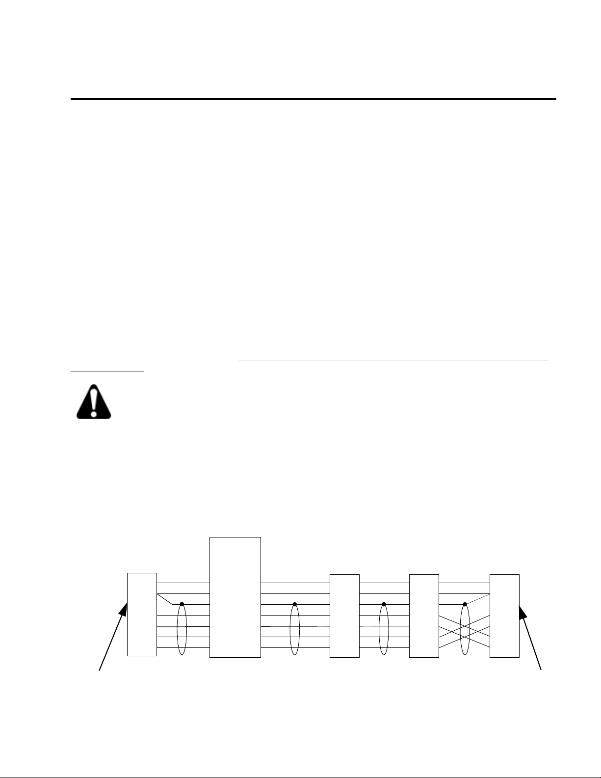
Figure 1: RS-485 Communication Wiring for RRM and RIM as last device
Terminate
Here
Terminate
Here
The Surface Mount Remote Relay Module (RRM) provides an interface between the ACU Controller and eight
Single Pole Double Throw (SPDT) and eight Double Pole Double Throw (DPDT) dry contact relays. The RRM
consists of an electronic circuit board with an on board screw terminal connectors. (The RRM with backplate only
is Product Number RRM16-E1L) The RRM can be installed in its own tampered enclosure. (The RRM with key
locked enclosure is Product Number RRM16-E00)
When attaching this device to a Summit system, please refer to the ACU3 Family Installation and Opera-
tion Guide for the list of input and output assignments.
Surface Mount (SMT) refers to a method of construction that allows the various module components to
be mounted directly on the surface of the board rather than using the traditional thru-hole method.
The RRM Each relay is rated 2 Amps at 30 VDC.
Two unsupervised inputs are available for power fault and cabinet tamper.
The Remote Relay Module requires 24 VDC (±15%).
The switches on the RRM are dynamic and can be changed while power is still applied to the board.
Changes will take effect immediately.
Auxiliary Power Supply for RRM
In many cases the ACU can supply the power for the RRM. The exception is when using an ACURS with a plugin transformer for its power supply. When the ACU cannot supply power, an auxiliary power supply must be used.
When using an auxiliary power supply make sure the 0V terminal on all remote modules and the ACU share a
common ground.
Do not use the relays on the ACU Controller, Remote Reader Electronics (RRE), Remote Input
Module (RIM) or Remote Relay Module (RRM) to switch any voltage above 30 volts. Failure to
heed this WARNING can cause death, personal injury or damage to unit(s).
RS-485 Information
RS-485 is a differential voltage communication circuit. The Impedance is 120 ohms. End-of-line terminators are
required on both ends of the communications path (See diagram below). Multi-drop configurations are allowed
with a maximum length of 4,000 feet. Stubs can be dropped, off the RS-485 cable, but the length of any stub
cannot be longer than 10 feet. Stubs can connect to ACU Controllers or remote modules (One-Stage reader,
RRE, RIM or RRM). Stubs must not be terminated. UTC Fire & Security strongly recommends star
configurations be avoided. The all remote modules have built-in terminators that are switch selectable.
RS-485 Wiring Diagram
3
Page 4
Surface Mount Remote Relay Module Installation Guide
ON
A
B
C
TX
RX
16
15
14
13
12
11
10
9
8
7
6
5
4
3
2
1
SW1
SW2
J2
TB1
TB2TB3
TB4TB5
TB6
K1 K2
K3 K4
K5 K6
K11 K9
K16 K14
K15 K13
K8
K12
K7
K10
ON
1
ON
1
T+ T- R+ R-
GND
GND
GND
GND
VIN
I1 I2
C NC NOK8C NC NOK8C NC NOK9C NC NO
K10
C NC NO
K11
C NC NOK5C NC NOK4C NC NOK4C NC NOK3C NC NO
K3
K7
NO NC CK7NO NC CK6NO NC CK6NO NC CK5NO NC C
K12
NO NC C
K13
NO NC C
K14
NO NC C
K15
NO NC C
K16
NO NC C
K2
NO NC CK2NO NC CK1NO NC CK1NO NC C
UTC FIRE & SECURITY
REMOTE RRELAY MODULE
U1
SW2 See:
Table 9
TB1 See:
Table 1
TB3 See:
Table 6
TB2 See:
Table 7
TB6 See:
Table 3
TB5 See:
Table 4
TB4 See:
Table 5
LEDs See:
Table 2
SW1 See:
Table 8
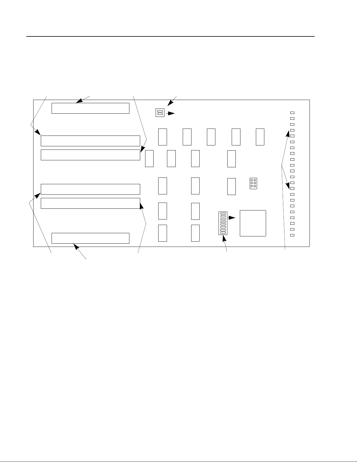
RRM SMT Circuit Board
Figure 2 shows the location of components discussed in this section for the RRM.
4
Figure 2: Locations of Components on SMT RRM
Page 5

Terminal Block Connector PIN Numbers on the RRM
Terminal Block Connector PIN Numbers on the RRM
Table 1 though Table 6 shows RRM terminal block wiring connections. Refer to the ACU Networked
Intelligent Controllers Installation Guide Chapter 3 for applicable ACU Controller connections and cable
identifications.
Connections on RRM
TB
Number
TB1 I1 Unsupervised Alarm 1
TB1 I2 Unsupervised Alarm 2
TB1 GND Alarm common ground
TB1 GND Alarm common ground
TB1 T+ To ACU Expansion Port RX+
TB1 T- To ACU Expansion Port RX-
TB1 R+ From ACU Expansion Port TX+
TB1 R- From ACU Expansion Port TX-
TB1 GND Ground
TB1 GND Ground
TB1 VIN + 24 Volts In
Table 1: RRM Wiring Connections for Expansion Port
Pin
No.
Normal Operation LED’s on the RRM
LED Description
A ON steady when board is Online
B Heart beat 1 flash per second
C Flashing when offline
Tx Flashing when transmitting data to ACU
Rx Flashing when receiving data from ACU
ON ON when Power is applied
LED’s 1 - 16
One LED per Relay
LED is ON when relay is energized
Description
Table 2: RRM Normal LED Operation
5
Page 6

Surface Mount Remote Relay Module Installation Guide
Connections for Relays K1 & K2 on RRM
TB
Number
TB6 K2 NO Relay 2 Normally Open
TB6 K2 NC Relay 2 Normally Closed
TB6 K2 C Relay 2 Common
TB6 K2 NO Relay 2 Normally Open
TB6 K2 NC Relay 2 Normally Closed
TB6 K2 C Relay 2 Common
TB6 K1 NO Relay 1 Normally Open
TB6 K1 NC Relay 1 Normally Closed
TB6 K1 C Relay 1 Common
TB6 K1 NO Relay 1 Normally Open
TB6 K1 NC Relay 1 Normally Closed
TB6 K1 C Relay 1 Common
Table 3: RRM Wiring Connections for Relays K1 & K2
Pin
No.
Connections for Relays K3 – K5 on RRM
TB5 K5 C Relay 5 Common
TB5 K5 NC Relay 5 Normally Closed
TB5 K5 NO Relay 5 Normally Open
TB5 K4 C Relay 4 Common
TB5 K4 NC Relay 4 Normally Closed
TB5 K4 NO Relay 4 Normally Open
TB5 K4 C Relay 4 Common
TB5 K4 NC Relay 4 Normally Closed
TB5 K4 NO Relay 4 Normally Open
TB5 K3 C Relay 3 Common
TB5 K3 NC Relay 3 Normally Closed
TB5 K3 NO Relay 3 Normally Open
TB5 K3 C Relay 3 Common
TB5 K3 NC Relay 3 Normally Closed
TB5 K3 NO Relay 3 Normally Open
Description
Table 4: RRM Wiring Connections for Relays K3 - K5
6
Page 7

Connections for Relays K5 - K7 on TB4
Terminal Block Connector PIN Numbers on the RRM
TB
Number
TB4 K7 NO Relay 7 Normally Open
TB4 K7 NC Relay 7 Normally Closed
TB4 K7 C Relay 7 Common
TB4 K7 NO Relay 7 Normally Open
TB4 K7 NC Relay 7 Normally Closed
TB4 K7 C Relay 7 Common
TB4 K6 NO Relay 6 Normally Open
TB4 K6 NC Relay 6 Normally Closed
TB4 K6 C Relay 6 Common
TB4 K6 NO Relay 6 Normally Open
TB4 K6 NC Relay 6 Normally Closed
TB4 K6 C Relay 6 Common
TB4 K5 NO Relay 5 Normally Open
TB4 K5 NC Relay 5 Normally Closed
TB4 K5 C Relay 5 Common
Table 5: RRM Wiring Connections for Relays K5-K7
Pin
No.
Description
7
Page 8

Surface Mount Remote Relay Module Installation Guide
Connections for Relays K8 - K11 on TB3
TB
Number
TB3 K8 C Relay 8 Common
TB3 K8 NC Relay 8 Normally Closed
TB3 K8 NO Relay 8 Normally Open
TB3 K8 C Relay 8 Common
TB3 K8 NC Relay 8 Normally Closed
TB3 K8 NO Relay 8 Normally Open
TB3 K9 C Relay 9 Common
TB3 K9 NC Relay 9 Normally Closed
TB3 K9 NO Relay 9 Normally Open
TB3 K10 C Relay 10 Common
TB3 K10 NC Relay 10 Normally Closed
TB3 K10 NO Relay 10 Normally Open
TB3 K11 C Relay 11 Common
TB3 K11 NC Relay 11 Normally Closed
TB3 K11 NO Relay 11 Normally Open
Table 6: RRM Wiring Connections for Relays K8-K11
Pin
No.
Description
8
Page 9

Connections for Relays K12 - K16 on TB2
Setting the DIP Switches on the SMT RRM
TB
Number
TB2 K12 NO Relay 12 Normally Open
TB2 K12 NC Relay 12 Normally Closed
TB2 K12 C Relay 12 Common
TB2 K13 NO Relay 13 Normally Open
TB2 K13 NC Relay 13 Normally Closed
TB2 K13 C Relay 13 Common
TB2 K14 NO Relay 14 Normally Open
TB2 K14 NC Relay 14 Normally Closed
TB2 K14 C Relay 14 Common
TB2 K15 NO Relay 15 Normally Open
TB2 K15 NC Relay 15 Normally Closed
TB2 K15 C Relay 15 Common
TB2 K16 NO Relay 16 Normally Open
TB2 K16 NC Relay 16 Normally Closed
TB2 K16 C Relay 16 Common
Table 7: RRM Wiring Connections for Relays K12-K16
Pin
No.
Description
Setting the DIP Switches on the SMT RRM
SW1 Settings on RRM
1 = OFF 2 = OFF Address 4
Switches 1,2 - Communication
Address:
Switch 3 Spare
Switch 4 Spare
Switch 5 Spare
Switch 6 Spare
Switch 7 Spare
Switch 8 Spare
Table 8: RRM DIP Switch SW1 Settings
1 = ON 2 = OFF Address 5
1 = OFF 2 = ON Address 6
1 = ON 2 = ON Address 7
9
Page 10

Surface Mount Remote Relay Module Installation Guide
SW2 Settings on SMT RRM
The 2-position DIP switch - SW2, located on the RRM (Figure 2), is used to terminate the RS-485 communications.
Switch
Number
SW2-1 ON Termination of Receive Pair
SW2-2 ON Termination of Transmit Pair
Table 9: RRM DIP Switch SW2 Settings
Alarm Numbers on the SMT RRM
Zone
Input
IN1 97 101 105 109 113 117 121 125
IN2 98 102 106 110 114 118 122 126
Offline 99 103 107 111 115 119 123 127
Expansion Port 1 Address: Expansion Port 2 Address:
45674567
Table 10: RRM Alarm Numbers for the Host PC
Function
10
Page 11

Relay Numbers on the SMT RRM
Relay Numbers on the SMT RRM
Relay
Number
K1 112 128 144 160 48 64 80 96
K2 113 129 145 161 49 65 81 97
K3 114 130 146 162 50 66 82 98
K4 115 131 147 163 51 67 83 99
K5 116 132 148 164 52 68 84 100
K6 117 133 149 165 53 69 85 101
K7 118 134 150 166 54 70 86 102
K8 119 135 151 167 55 71 87 103
K9 120 136 152 168 56 72 88 104
K10 121 137 153 169 57 73 89 105
K11 122 138 154 170 58 74 90 106
K12 123 139 155 171 59 75 91 107
K13 124 140 156 172 60 76 92 108
K14 125 141 157 173 61 77 93 109
K15 126 142 158 174 62 78 94 110
K16 127 143 159 175 63 79 95 111
Expansion Port 1 Address: Expansion Port 2 Address:
45674567
Table 11: RRM Relay Numbers for the Host PC
11
Page 12

Surface Mount Remote Relay Module Installation Guide
RRM Field Wiring Test
After making all connections, the following tests should be made. Connections should already be completed at the ACU and the auxiliary power supply if used.
Test points and expected voltages
From To Voltage Tolerance
GND VIN + 24 VDC 3.5 VDC
T+ T- + 4.0 VDC* 0.5 VDC
R+ R- + 2.5 VDC * 0.5 VDC
+24V Bldg. Gnd. 24 VDC 3.5 VDC
GND Bldg. Gnd. 0 VDC 0.5 VDC
T+ Bldg. Gnd. Less than 6.0 VDC N/A
T- Bldg. Gnd. Less than 6.0 VDC N/A
R+ Bldg. Gnd. Less than 6.0 VDC N/A
R- Bldg. Gnd. Less than 6.0 VDC N/A
Table 12: RRM Test points and Voltages
* After the first reader is connected these voltages will modulate due to data on the line. Most Digital
Volt Meters should indicate about 2.0 VDC.
Power-Up Self-Test on the RRM
The Remote Relay Module should always be tested after installation. The indicators for the RRM are the
red LED’s located on the component board. The test should be completed in less than 10 seconds. The
LED’s will light as follows:
LED Description
A ON at power-up
B ON when successful RAM test is finished
C ON when successful PROM test and initialization completed
ON ON when Power is applied
Table 13: Power-up LED Indicators on the RRM
After all three LED’s have lit, LED B will flash at a 1 Hz rate.
12
 Loading...