

Page 1

Remote Input Module
User Manual
Page 2

Copyright Copyright © 2010, UTC Fire & Security. All rights reserved.
This document may not be copied in whole or in part, or otherwise reproduced except as specifically
permitted under US copyright law, without the prior written consent from UTC Fire & Security.
Document number/revision: 1054312D.
Disclaimer The information in this document is subject to change without notice. UTC Fire & Security accepts
Trademarks and patents Trade names used in this document may be trademarks or registered trademarks of the manufac-
Software license
agreement
Intended use Use this product only for the purpose for which it was designed; refer to the data sheet and user
FCC compliance This equipment has been tested and found to comply with the limits for a Class A digital device,
no responsibility for inaccuracies or omissions and specifically disclaims any liabilities, losses, or
risks, personal or otherwise, incurred as a consequence, directly or indirectly, of the use or application of any of the contents of this document.
This publication may contain examples of screen captures and reports used in daily operations.
Examples may include fictitious names of individuals and companies. Any similarity to names and
addresses of actual businesses or persons is entirely coincidental.
turers or vendors of the respective products.
UTC Fire & Security software supplied with UTC Fire & Security products is proprietary and
furnished under license and can be used or copied only in accordance with the license terms.
THE ENCLOSED PROGRAM IS FURNISHED SUBJECT TO THE TERMS AND CONDITIONS OF
THIS AGREEMENT. RETENTION OF THE PROGRAM FOR MORE THAN 30 DAYS, OPENING
OF THE SEALED WRAPPER, IF ANY, SURROUNDING THE PROGRAM, OR USE OF THE
PROGRAM IN ANY MANNER WILL BE CONSIDERED ACCEPTANCE OF THE AGREEMENT
TERMS. IF THESE TERMS ARE NOT ACCEPTABLE, RETURN THE UNUSED PROGRAM AND
ANY ACCOMPANYING DOCUMENTATION TO GE FOR A FULL REFUND OF THE LICENSE FEE
PAID. (FOR INFORMATION REGARDING THE RETURN OF PROGRAMS ENCODED OR
INCORPORATED WITHIN EQUIPMENT, CONTACT THE NEAREST UTC FIRE & SECURITY
SALES OFFICE.)
documentation. For the latest product information, contact your UTC Fire & Security sales representative or visit us online at www.UTCFireandSecurity.com.
pursuant to part 15 of the FCC Rules. These limits are designed to provide reasonable protection
against harmful interference when the equipment is operated in a commercial environment. This
equipment generates, uses, and can radiate radio frequency energy and, if not installed and used in
accordance with the instruction manual, may cause harmful interference to radio communications.
You are cautioned that any changes or modifications not expressly approved by the party responsible for compliance could void the user's authority to operate the equipment.
Page 3

Remote Input Module
WARNING
The Remote Input Module (RIM) provides the interface between the ACU Controller and additional alarm
sensors. The RIM consists of the electronic circuit board and the screw terminal connector board connected
together by a ribbon cable. The RIM can be installed in its own tampered enclosure.
Note: The RIM with backplate only is Product Number RIM16-E00.
The RIM with key locked enclosure is Product Number RIM16-E1L.
• When attaching a RIM to a Summit system, please refer to the ACU3 Family Installation and
Operation Guide for the list of input and output assignments.
• Surface Mount (SMT) refers to a method of construction that allows the various module components to
be mounted directly on the surface of the board rather than using the traditional thru-hole method.
• Each RIM provides 16 supervised inputs, 3 unsupervised inputs and 2 relay outputs (wet or dry contact
relays Single Pole Double Throw).
• The Remote Input Module connects to the expansion port on the ACU in the upper addresses (4-7)
only. Each expansion port can support four readers in addition to remote modules (RIM, RRM).
• Each of the 16 alarm inputs is supervised as 6-states, Alarm, Secure, Open, Shorted, Ground and
Circuit Fault.
1
Auxiliary Power Supply for RIM
In many cases, the ACU can supply the power for the RIM. The exception is when using an ACURS with a
plug-in transformer for its power supply. When the ACU can not supply power an auxiliary power supply must
be used. When using an auxiliary power supply, make sure the 0V terminal on all remote modules and the
ACU share a common ground.
The Remote Input Module requires 24 VDC (±15%).
Do not use the relays on the ACU Controller, Remote Reader Electronics (RRE), Remote Input Module
(RIM) or Remote Relay Module (RRM) to switch any voltage above 30 volts. Failure to heed this
WARNING can cause death, personal injury or damage to unit(s).
RS-485 Information
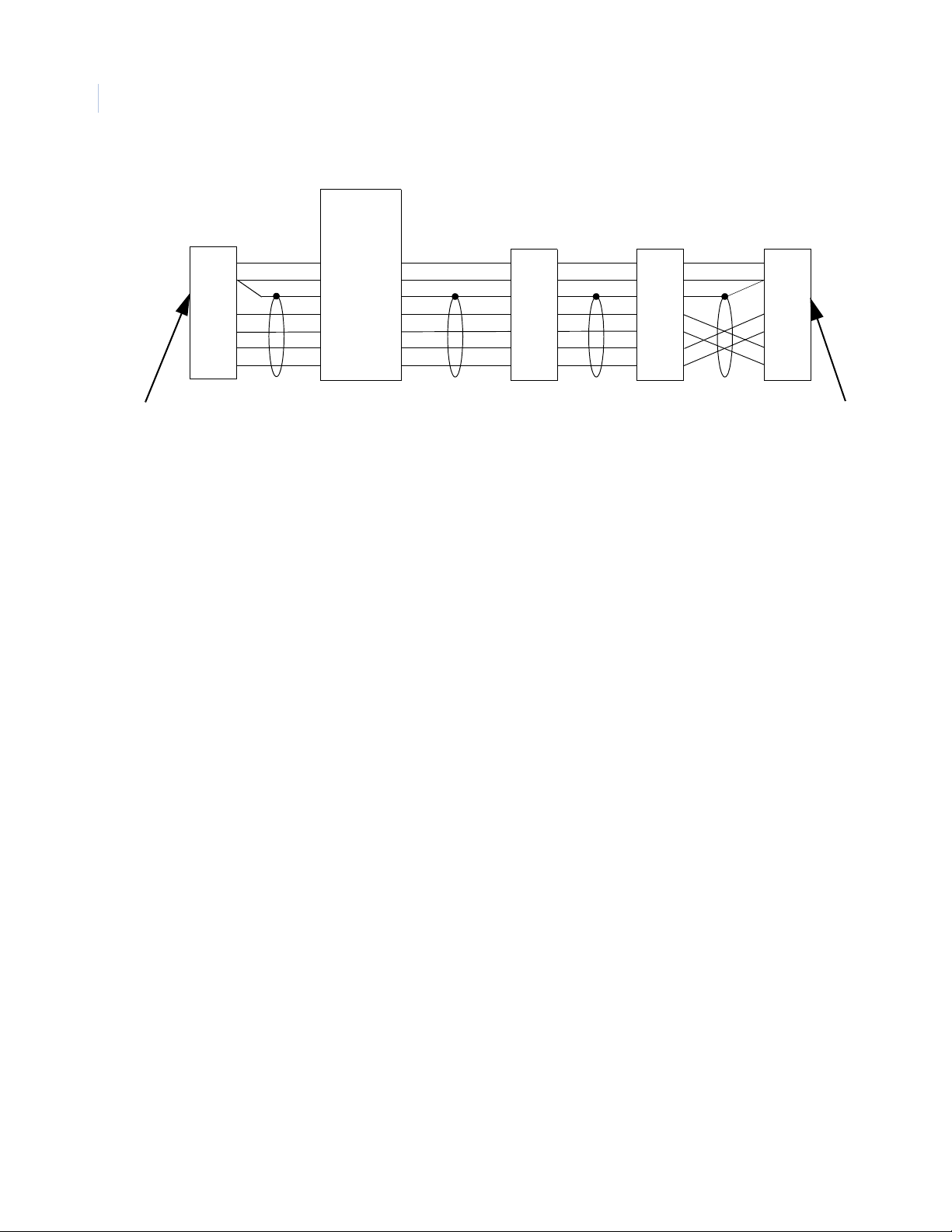
RS-485 is a differential voltage communication circuit. The Impedance is 120 ohms. End-of-line terminators
are required on both ends of the communications path (See Figure 1). Multi-drop configurations are allowed
with a maximum length of 4,000 feet (1,219 meters).
Stubs can be dropped, off the RS-485 cable, but the length of any stub cannot be longer than 10 feet (3
meters). Stubs can connect to ACU Controllers or remote modules (One-Stage reader, RRE, RIM or RRM).
Stubs must not be terminated. We strongly recommend that star configurations be avoided. All remote
modules have built-in terminators that are switch selectable.
Page 4
Remote Input Module
+24
0V
TT+
RR+
+24
0V
TT+
RR+
+24
0V
TT+
RR+
+24
0V
TT+
RR+
ACUX
Readers
Port
RRE
or
Reader
RRE
or
Reader
RRM
or
RIM
+24
0V
TT+
RR+
RRE
or
Reader
Figure 1. RS-485 Communication Wiring for RRM and RIM as last device
Terminate
Here
Terminate
Here
2
User Manual
RS-485 Wiring
Page 5
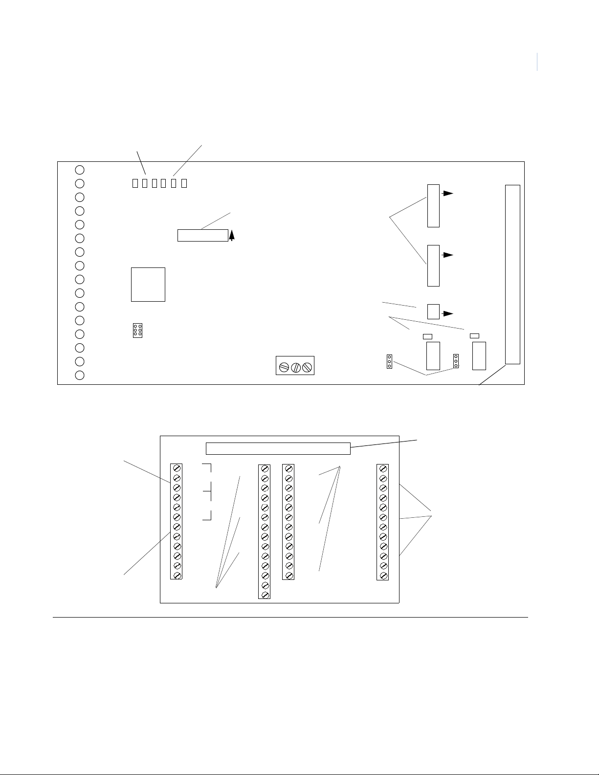
SMT RIM Board Layout
D57
W1
A B C Tx Rx ON
SW1
SW3
SW4
SW2
1
2
3
4
5
6
7
8
9
10
11
12
13
14
15
16
1
1
1
ON
ON
ON
Termination Board
Ribbon Connector
LEDs
J2
+12V 0V +24V
UTC FIRE & SECURITY
REMOTE INPUT MODULE
K1
K2
U3
ON
D52
Figure 2. SMT RIM Component Location
1
See Table 7.
See Table 9.
See Table 8.
W2
See Table 10.
See Table 11.
See Table 11.
TB7
TB8
TB4
IN1
IN1
IN2
IN2
IN3
IN3
IN4
IN4
IN5
IN5
IN6
IN6
IN12
IN12
IN11
IN11
IN10
IN10
IN9
IN9
IN8
IN8
IN7
IN7
IN13
IN13
IN14
IN14
IN15
IN15
IN16
IN16
IN17
GND
IN18
GND
IN19
GND
NO
NC
C
NO
NC
C
+24V
GND
RR+
TT+
UTC FIRE & SECURITY
16-Input Termination
K2
K1
TB9
TB11
TB6
TB5
TB10
TB1
TB2
TB3
See Table 3.
See Table 4.
See Table 1.
See Table 5.
See Table 2.
Termination Board
Ribbon Connector
3
Figure 3. PIN Locations on the Terminal Board of the SMT RIM
Page 6
Remote Input Module
4
User Manual
Terminal Block Output Connections
Table 1. Wiring the Output Connections on the SMT Remote Input Module
Pin
TB
Table 2. Wiring the Communication Connections on the SMT Remote Input Module
TB
11 1 +24V + 24 Volts In
11 2 G N D 0 V
11 3 R- To ACU Expansion Port TX -
11 4 R+ To ACU Expansion Port TX+
11 5 T- To ACU Expansion Port RX-
No.
9 1 K2 N.O. Aux Relay 2 Normally Open
9 2 K2 N.C. Aux Relay 2 Normally Closed
9 3 K2 C. Aux Relay 2 Common
9 4 K1 N.O. Aux Relay 1 Normally Open
9 5 K1 N.C. Aux Relay 1 Normally Closed
9 6 K1 C. Aux Relay 1 Common
Pin
No.
Term.
Strip
Term.
Strip Description
Description
11 6 T+ To ACU Expansion Port RX+
Page 7

Table 3. RIM Wiring Connections for TB1 - TB3
5
TB
Pin
No.
Ter m.
Strip
Description
1 1 IN1 Zone Input 1
1 2 IN1 Zone Input 1
1 3 IN2 Zone Input 2
1 4 IN2 Zone Input 2
2 1 IN3 Zone Input 3
2 2 IN3 Zone Input 3
2 3 IN4 Zone Input 4
2 4 IN4 Zone Input 4
3 1 IN5 Zone Input 5
3 2 IN5 Zone Input 5
3 3 IN6 Zone Input 6
3 4 IN6 Zone Input 6
Table 4. Connections for TB4, TB7 and TB8 on RIM
TB
Pin
No.
Ter m.
Strip
Description
7 1 IN12 Zone Input 12
7 2 IN12 Zone Input 12
7 3 IN11 Zone Input 11
7 4 IN11 Zone Input 11
8 1 IN10 Zone Input 10
8 2 IN10 Zone Input 10
8 3 IN9 Zone Input 9
8 4 IN9 Zone Input 9
4 1 IN8 Zone Input 8
4 2 IN8 Zone Input 8
4 3 IN7 Zone Input 7
4 4 IN7 Zone Input 7
Page 8

Remote Input Module
6
User Manual
Table 5. Connections for TB5, TB6, and TB10 on RIM
Pin
TB
10 1 IN17 Unsupervised Zone Input 17
10 2 GND Ground
10 3 IN18 Unsupervised Zone Input 18
10 4 GND Ground
10 5 IN19 Unsupervised Zone Input 19
10 6 GND Ground
No.
6 1 IN13 Zone Input 13
6 2 IN13 Zone Input 13
6 3 IN14 Zone Input 14
6 4 IN14 Zone Input 14
5 1 IN15 Zone Input 15
5 2 IN15 Zone Input 15
5 3 IN16 Zone Input 16
5 4 IN16 Zone Input 16
Ter m.
Strip
Description
Input State Standard Resistance Ranges for Troubleshooting
When correctly wired, the input terminals should test with the default resistance listed in the table below. The
end-of-line (EOL) resistor for the SECURE state is 1,000 Ohms as selected using the DIP switch settings. The
End-Of-Line resistors must be located within the alarm zone sensor enclosure or the alarm zone circuit will be
considered unsupervised.
When 1000 Ohms terminators are used, the sensors can be wired for either normally closed contacts or
normally open contacts. In either case, the SECURE or inactive state should test at 1,000 ohms. A pair of 1 K
ohm resistors, at the sensor end of each alarm circuit, ensures that the line resistance is typically 1 K ohm when
the alarm is in the secure state.
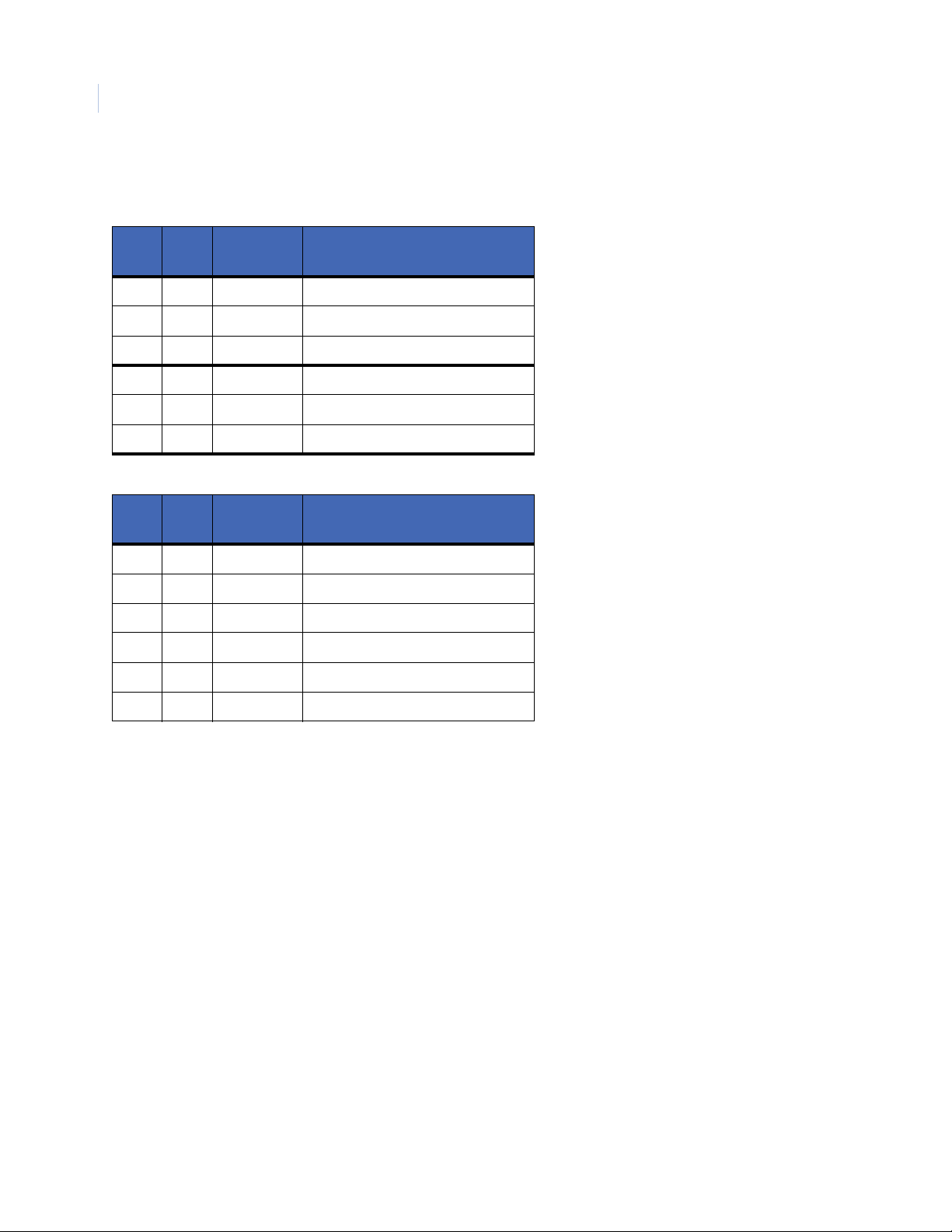
Table 6. Input Zone Status By Resistance
Zone Input
State
Secure 1000 1000
Active 2000 500
Open > 50,000 > 50,000
Short < 50 < 50
Sensor Circuit in Ohms
Normally Closed
Sensor Circuit in Ohms
Normally Open
Page 9

7
Figure 4. Zone Sensor 1000 Ohms Resistors
Page 10

Remote Input Module
8
User Manual
Setting the DIP Switches on the SMT RIM
SW1 Switch Settings
Note: The use of SW1-7 to provide the 200/10K termination option is available with firmware version 3.07 or later.
Table 7. RIM DIP Switch Settings
Switch Number Description
SW1-1 SW1-2 Module address:
Off Off Addr 4
On Off Addr 5
Off On Addr 6
On On Addr 7
SW1-4 Alarm Latching:
On Enables latching – Associated LEDs for
zones 1—16 will latch on alarm. Zone 18
will reset cleared zone LEDs.
Off Disables latching
SW1-3 SW1-5 SW1-6 Zone Termination:
Off Off Off 0.5K alarm, 1K safe, 2K alarm
On Off Off 75 ohms alarm, 150 safe, 300 alarm
Off On Off 1K safe, 3K alarm, 5—7K ground
On On Off 1K safe, 3K alarm
Off Off On 6.8K safe, 24K alarm
On Off On 1.5K safe, 3K alarm
Off On On 10K safe, 5K alarm
On On On 5K safe, 10K alarm
SW1-3 SW1-5 SW1-6 SW1-7 Zone Termination
Off Off Off On 200 ohms safe, 10K alarm
Switch 8 is a spare
Page 11

SW2 Switch Settings for RS485 Termination
The 2-position DIP switch SW2 located on the RIM is used to terminate the RS485 communication when
required.
Table 8. SMT RIM Switch SW2 for RS485 Termination
Switch SW2 Description
SW2-1 ON Termination of Receive Pair
SW2-2 ON Termination of Transmit Pair
SW3 and SW4 Switch Settings for Input Zone Termination
The 8-position DIP switch (SW3 and SW4) located on the RIM are used to terminate the unused RIM Inputs.
The switch in ON position will terminate the zone with 1K resister.
Table 9. SMT RIM Switch SW3 and SW4 for Input Termination
Switch Description
9
SW3-1 Zone 0 Termination
SW3-2 Zone 1 Termination
SW3-3 Zone 2 Termination
SW3-4 Zone 3 Termination
SW3-5 Zone 4 Termination
SW3-6 Zone 5 Termination
SW3-7 Zone 6 Termination
SW3-8 Zone 7 Termination
Switch Description
SW4-1 Zone 8 Termination
SW4-2 Zone 9 Termination
SW4-3 Zone 10 Termination
SW4-4 Zone 11 Termination
SW4-5 Zone 12 Termination
SW4-6 Zone 13 Termination
SW4-7 Zone 14 Termination
SW4-8 Zone 15 Termination
Page 12

Remote Input Module
10
User Manual
Setting the Jumpers on the SMT RIM
Jumper W1 and W2 Settings
Jumpers W1 and W2 located on the RIM () are used to select if 24 VDC will be supplied by relays K1 and K2
on the RIM.
Table 10. SMT RIM Jumpers W1 and W2
Jumper Description
W1 Jump pins 2 & 3 Relay K1 Dry
W1 Jump pins 1 & 2 Relay K1 energized with +24 V
W2 Jump pins 2 & 3 Relay K2 Dry
W2 Jump pins 1 & 2 Relay K2 energized with +24 V
Normal LED status on the SMT RIM
The LEDs on the Remote Input Module will light as follows:
Table 11. SMT RIM Normal LED Status
LED Description
A On when board is Communicating to ACU
B Heart 1 Hz Flash - CPU is functioning correctly
C Flashing when offline
Tx Flashing when transmitting data to ACU
Rx Flashing when receiving data from ACU
ON ON when Power is applied to board
D57 ON when relay 2 is energized
D52 ON when relay 1 is energized
Status of 16 Alarm points Green - Secure
LEDs 1 - 16
Red - Active
Yellow - Trouble
Page 13

Alarm Numbers on RIM
RIM Alarm Numbers for the Host PC
Table 12. RIM Alarm Numbers for the Host PC
11
Zone
Input
IN1 128 144 160 176 192 208 224 240
IN2 129 145 161 177 193 209 225 241
IN3 130 146 162 178 194 210 226 242
IN4 131 147 163 179 195 211 227 243
IN5 132 148 164 180 196 212 228 244
IN6 133 149 165 181 197 213 229 245
IN7 134 150 166 182 198 214 230 246
IN8 135 151 167 183 199 215 231 247
IN9 136 152 168 184 200 216 232 248
IN10 137 153 169 185 201 217 233 249
IN11 138 154 170 186 202 218 234 250
IN12 139 155 171 187 203 219 235 251
IN13 140 156 172 188 204 220 236 252
IN14 141 157 173 189 205 221 237 253
Expansion Port 1 Address: Expansion port 2 Address:
4 5 6 7 4 5 6 7
IN15 142 158 174 190 206 222 238 254
IN16 143 159 175 191 207 223 239 255
IN17 96 100 104 108 112 116 120 124
IN18 97 101 105 109 113 117 121 125
IN19 98 102 106 110 114 118 122 126
Offline 99 103 107 111 115 119 123 127
Page 14

Remote Input Module
12
User Manual
Relay Numbers on RIM
Table 13. RIM Relay Numbers for the Host PC
Relay
Number
K1 32 34 36 38 40 42 44 46
K2 33 35 37 39 41 43 45 47
Expansion port 1 Address: Expansion port 2 Address:
4 5 6 7 4 5 6 7
RIM Field Wiring Test
After making all connections and prior to connecting the ribbon cable to the RIM, the following tests should be
made. Connections should already be completed at the ACU and external power supply if used.
Table 14. RIM Test Points and Voltages
From To Vol tag e Tolerance
GND +24V + 24 VDC 3.5 VDC
T+ T- + 4.0 VDC* 0.5 VDC
R+ R- + 2.5 VDC * 0.5 VDC
+24V Bldg. Gnd. 24 VDC 3.5 VDC
GND Bldg. Gnd. 0 VDC 0.5 VDC
T+ Bldg. Gnd. Less than 6.0 VDC N/A
T- Bldg. Gnd. Less than 6.0 VDC N/A
R+ Bldg. Gnd. Less than 6.0 VDC N/A
R- Bldg. Gnd. Less than 6.0 VDC N/A
* After the first expansion module is connected, these voltages will modulate due to data on the line.
Most Digital Volt Meters should indicate about 2.0 VDC.
Page 15

Power-Up Self Test on the RIM
The Remote Input Module should always be tested after installation. The indicators for the RIM are the red
LEDs located on the component board. See Figure 2 for the locations of these LEDs.
Note: The test will complete in less than 10 seconds after power-up.
Table 15. Power-up LED Indicators on the RIM
LED Description
A ON at power-up
B ON RAM test successful
C ON PROM tested and initialized
ON ON when Power is applied
LEDs 1 - 16 All Green, then All Yellow, then All Red
13
Page 16

Remote Input Module
14
User Manual
Contacting technical support
For assistance with this product, refer to this document and any other documentation provided. If you still have
questions, you may contact technical support during normal business hours (Monday through Friday,
excluding holidays, between 8 a.m. and 7 p.m. Eastern Time).
Web site: www.utcfireandsecurity.com
Phone: 1 888 437 3287
Fax: 561 998 6224
Email: rs-bctsupport@fs.utc.com
Note: Be ready at the equipment before calling for technical support.
 Loading...