

Page 1

TruPortal System Controller Quick Reference
(for TP-SYS-BRD, TP-SYS-2D, TP-SYS-2D-E,
TP-SYS-2D2R) en-US
The TruPortal System Controller
The TruPortal System Controller provides a solution for access control. It
consists of two boards; the I/O board and the system on module (SOM)
board. The I/O board, the larger of the two, contains the power supply and
all field wiring connections. The SOM, the smaller mounted board, contains
the main CPU and memory.
The event log buffer and the real time clock are stored in battery-backed
memory. Each reader port can accommodate a reader that utilizes Wiegand
Data1/Data0, LED control, and buzzer control.
Twelve supervised inputs (excluding tamper and power monitor) are
provided for door sense, reader tamper, or request to exit as well as four
auxiliary supervised inputs.
Interfaces
The TruPortal System Controller interfaces upstream with the browserbased TruPortal User Interface. There is no dedicated host software to install
on operators’ workstations.
The TruPortal System Controller provides two (2) Ethernet ports.
Configuration data and event/status reports are exchanged with the user
interface via the primary Ethernet ports. The secondary port is not used.
Communication via modem is not supported.
Packing List
• TruPortal System Controller PCB assembly, which consists of the I/O
board and the SOM (quantity = 1)
• Two positional terminal plug-in block (quantity = 7)
• Three positional terminal plug-in block (quantity = 10)
• Four positional terminal plug-in block (quantity = 8)
• End of line resistors 1k ohm, 1% (quantity = 24)
• Push-fit terminal tab adapters (quantity = 2)
• Battery cable (quantity =1)
• Battery bracket (quantity = 1)
• Screws for battery bracket (quantity = 2)
• Strain relief for power cable (quantity = 1)
• Terminal block cover (quantity = 1)
• Lock (quantity = 1)
• Machine screws for securing the cover (quantity =6)
• Enclosure (depending on option ordered)
• Transformer (depending on option ordered)
• Credentials (depending on option ordered)
• T-100 Proximity Readers (depending on option ordered)
• TP-SYS-2D: TruPortal 2-Door base kit. Consists of a TruPortal
System Controller, installed in UL-listed enclosure with 4 amp power
supply.
• TP-SYS-2D2R: TruPortal 2-Door base kit with readers. Consists of a
TruPortal System Controller, installed in UL-listed enclosure with 4
amp power supply. Includes T-100 Readers (quantity = 2) and
Credentials (quantity = 5).
• TP-SYS-2D-E: TruPortal 2-Door base kit for EMEA. Consists of a
TruPortal System Controller, installed in CE-compliant enclosure with
4 amp power supply.
• -E Part number suffix for panel with CE enclosure (CE 220 VAC
internal transformer). Not evaluated by UL.
Model Numbers
The panels are available in the following configurations:
• TP-SYS-BRD: TruPortal System Controller. Board only. Capable of
controlling two (2) doors. No enclosure or readers.
TruPortal System Controller Quick Reference 1 P/N 460800001B 12JAN12 en-US
Page 2

System Capacities
Attribute TP-SYS
Attribute TP-SYS
Number of persons 10,000
Number of unique credentials 10,000
Credentials per person 5
Access levels 64
Access levels per credential 8
Schedules 64
Time intervals per schedule 6
Holiday groups per schedule 8
Holiday groups 8
Holidays per holiday group 32
Holidays (total) 255
Areas 64
Reader groups 64
Operator roles 32
User-defined fields 10
Video layouts 64
Card formats 8
Number of retained events in event log 65,000
Doors/Readers
Number of doors (base board and dual
door controllers) with readers in /
Number of doors with readers in and
out
TP-ADD-2D-BRD Dual Door Control
Modules (including built in)
64 / 32
32
Cameras per DVR
TVR10 (EMEA & US) 4
TVR30 (US Only) 16
Cameras (maximum) 64
Ethernet ports (total/supported) 2/1
RS-485 SNAPP bus ports 4
Anti-attack Bushing Cap
An anti-attack bushing cap covers a rear tamper spring. It fits inside an
O-ring bushing located in the cabinet’s rear wall anti-tamper spring
knockout. Leave the O-ring bushing and cap in place if the rear tamper is
not used.
If the rear tamper is used:
1. Remove the cap and the O-ring with the edge of a flat screwdriver.
2. Discard the O-ring.
3. Align the cap for the tamper spring and knockout hole on the cabinet
back.
4. Screw the cap into the mounting surface.
5. Place the control cabinet over it, allowing the rear tamper spring to fit
inside the cap. The cap will fit into the cabinet’s tamper spring
knockout hole.
6. Secure the cabinet to the mounting surface.
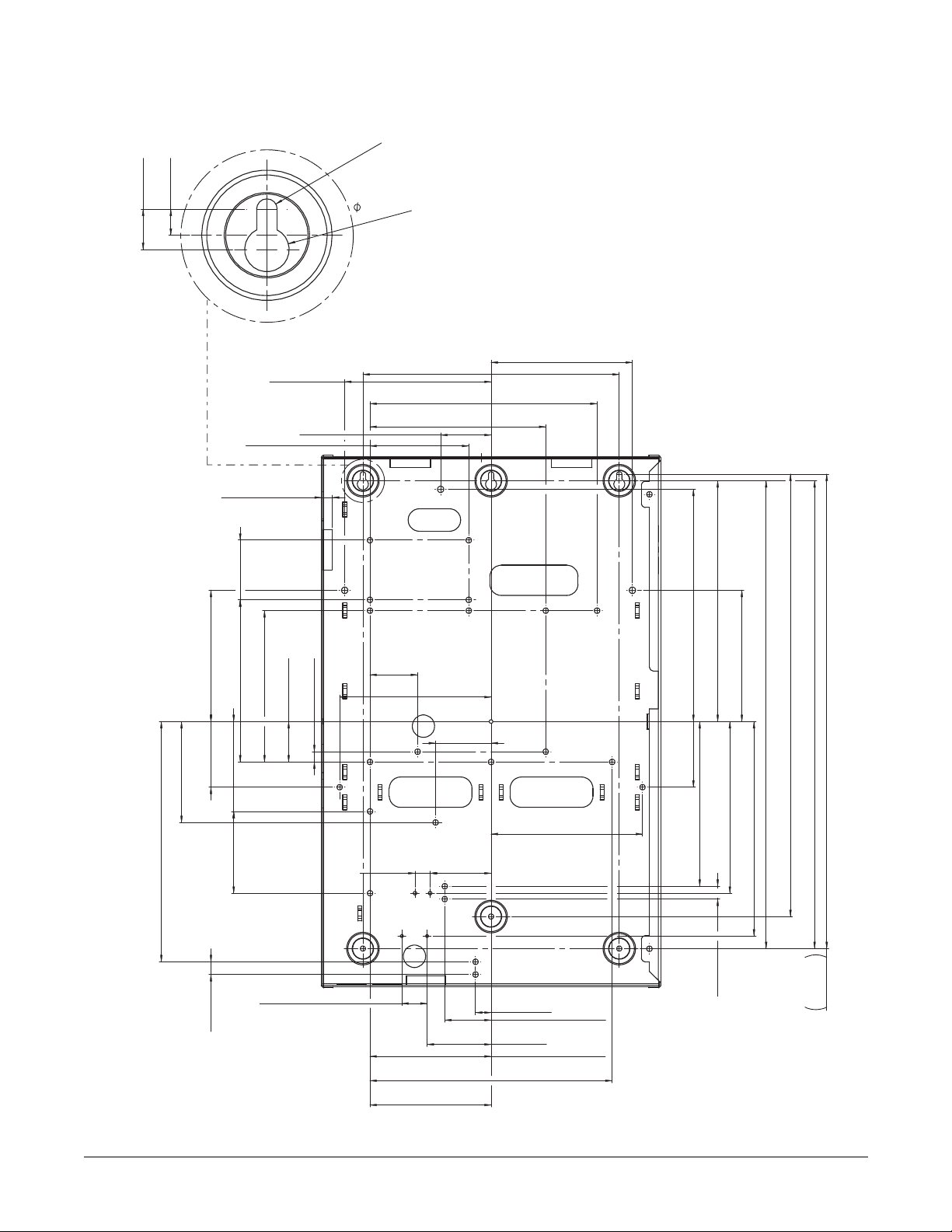
Mounting the Module
On dry wall, use 1/8 in. (3.175 mm) hollow wall, expansion anchors.
Unscrew the screws from the anchors. Mark the mounting holes. Force a
starter hole in each mark with a sharp tool. Hammer the anchors into each
hole. Align the box mounting holes over the anchor holes and screw in the
anchors until tight.
On a concrete surface, hold the control box on the mounting sur face . Mark
the mounting holes. Use a hammer drill with a 3/16 in. (4.76 mm) carballoy
drill bit and make 1in. (25.4 mm) deep holes in each marking. Insert a # 6-8
plastic anchor in each hole and hammer them in. Use # 8 X 1 in.(25.4 mm),
Phillips, wood screws to screw into the plastic anchors and mount the box.
See Figure 1 on page 9.
Readers (total) 64
Inputs/Outputs
Total number of system inputs
(including TruPortal System
Controller)
Total number of system outputs
(including TruPortal System
Controller)
Total number of TP-ADD-IO or TPADD-IO-BRD Input/Output
Expansion Add-Ons
DVR/Cameras
DVRs 4
TruPortal System Controller Quick Reference 2 P/N 460800001B 26JAN12 en-US
132
66
8
Communication Wiring
The controller communicates to the user interface via Ethernet.
The downstream communication ports are 2-wire RS-485 interfaces which
can be used to connect additional I/O panels. The interface allows multidrop communication on a single bus of up to 4000 feet (1200 m). Use
twisted pairs (minimum 22 AWG / 0.644 mm / 0.326 mm
shield for communication.
See Figure 2 on page 10.
2
) with an overall
Reader Wiring
Each reader port supports Wiegand Data1/Data0. Voltage at the reader port
is passed through from the input voltage of the controller and is limited to
250 mA.
The reader supply voltage is 14 VDC. Readers that require different voltage
should be powered separately. These readers may be connected and
Page 3
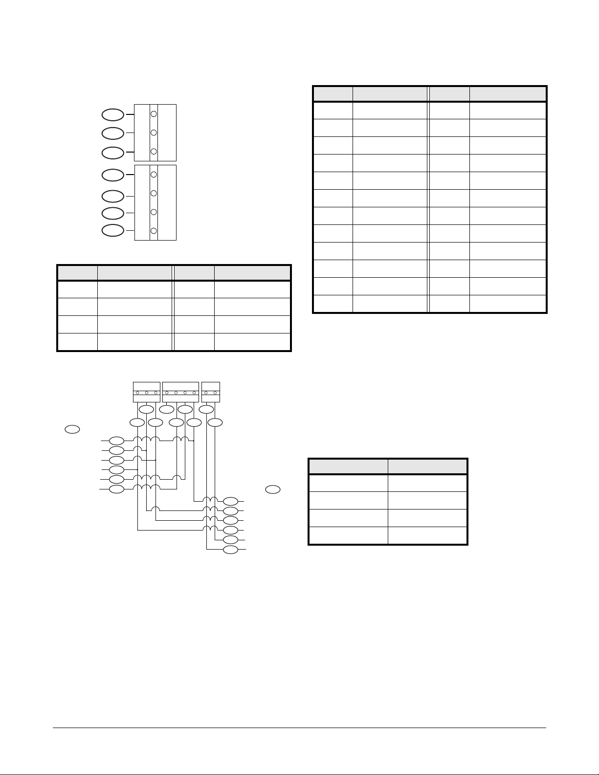
powered through the dual door interface module. Refer to the reader
CN10/CN17 CN11/CN18 CN12/CN19
BZ 14 GR RD D1 D0 0 A B
123 1234 12
5
4
1 3
2
10
9
6 8
7
15
14
13
12
11
20
19
18
17
16
23
22
21
manufacturer specifications for cabling requirements.
Reader wiring
BZ + GR RD D1 D0 0
1
2
3
4
5
6
7
123 1234
CN10/CN17
CN11/CN18
Callout Description Callout Description
1 Buzzer 13 LED
2 +14 V 14 Buzzer
3 Green LED 15 Data0
4 Red LED 16 Data1
5 D1 17 Data1
6 D0 18 Data0
7 0 V 19 Buzzer
8 D1 20 LED
9 D0 21 Power
Callout Description Callout Description
1 Buzzer 5 Data1
2 +14 V 6 Data0
3 Green LED 7 Ground
4 Red LED
Wiring In and Out readers
10 Reader (Out) 22 Ground
11 Ground 23 Reader (In)
12 Power
Input Circuit Wiring
Typically, these inputs are used to monitor door position, request to exit, or
alarm contacts. Input circuits are supervised. The input circuit is able to
report a condition of “Fault” for the status of the circuit, which appears as a
“Tamper” event fo r supervised conditions.
A supervised input circuit requires a resistor be added to the circuit to
facilitate proper reporting. The standard supervised circuit requires 1K ohm,
1% resistors and should be located as close to the sensor as possible.
Relay Circuit Wiring
All relays are dry contact.
Output 30 VDC rating
Siren relay 1 A
Strobe relay 1 A
Strike r elay 5 A
Aux relay 1 A
The relays for siren and door strike have a Common pole ( C), a Normally
Closed pole (NC), and a Normally Open pole (NO). When you are
TruPortal System Controller Quick Reference 3 P/N 460800001B 12JAN12 en-US
controlling the delivery of power to the door strike, the Normally Open and
Common poles are used. When you are momentarily removing power to
unlock the door, as with a mag lock, the Normally Closed and Common
poles are used. Check with local building codes for proper egress door
installation.
Power
The TruPortal System Controller requires 18 VAC or 24 VDC for input
power at CN2, or 12 VDC at CN1 (24 VDC and 12 VDC input power were
not evaluated by UL). When powering the board from 12 VDC, the onboard battery charger will not be used and the lead-acid backup battery
Page 4

should not be connected to the TP-SYS. The power supply providing the
1
2
CN1
CN2
12 0V
2
1
2
3
1
+12V
0V
DC+
0 V
CN2
1
2
3
AC
AC
3
12 VDC must have its own backup source.
TP-SYS 110/220 VAC Power wiring diagram
wires. The earth ground connection at CN2 Pin 2 is not required if the
controller board is grounded through the mounting screws.
Maximum lengths for wiring
I/O
Description
Connection Maximum
length of
22 AWG
Maximum line
resistance (in
Ohms)
wire (in
feet)
1
2
3
4
Callout Description Callout Description
1 Ground stud 3 Connections for AC
wiring
2 Red transformer
4 Wiring indication
wires
Power connectors
13.2 V supply
output
Supervised
inputs
5 A @ 24 VDC
relay output
(assume 15%
voltage drop)
CN3-1
CN3-3
CN10-2
CN17-2
CN21-1
CN23-1
CN24-1
CN25-1
CN26-1
CN8-1
CN8-3
CN9-1
CN9-3
CN15-1
CN15-3
CN16-1
CN16-3
CN21-2
CN21-4
CN22-1
CN22-3
CN7-1 (NO)
CN7-2 (C)
CN7-3 (NC)
CN14-1 (NO)
CN14-2 (C)
CN14-3 (NC)
300 approximately
4.8
500 approximately 8
45 approximately
0.72
1 A @ 24 VDC
relay output
(assume 15%
voltage drop)
Callout Description Callout Description
1 12 VDC input 3 18 VDC Input
CN4-1 (C)
CN4-2 (NC)
CN4-3 (NO)
CN5-1(C)
CN5-2 (NC)
CN13-1 (NO)
CN13-2 (C)
220 approximately
3.6
CN20-1 (NO)
2 24 VAC Input
The maximum input current is 2.7 A. The gauge is dependent on the length
of the wire. The TruPortal System Controller can be power ed by an internal
2
18 VAC transformer that uses 20 AWG (0.812 mm / 0.518 mm
) secondary
Note: These specified ranges have been verified by UL. Note that if
you run a longer wire, it is not verified by UL.
This equipment must be permanently connected to a mains fused spur (3 A
CN20-2 (C)
or 5 A) using 3-core cable with each core being no less than 18 AWG (1.024
mm / 0.823 mm
2
). The mains cable should be clamped securely with the
cable clamps provided within the equipment/installation kit. Knockouts are
provided on the top, bottom and sides of this equipment and these are
intended for conduit or cable glands. As a mains switch is not provided on
the equipment, a readily accessible disconnect device shall be incorporated
in the building installation wiring. Where there is doubt as to the phase of
this wiring, the device, when operated, will disconnect both poles
simultaneously.
TruPortal System Controller Quick Reference 4 P/N 460800001B 26JAN12 en-US
Page 5

Mains Supply
Item North
America
product
Internal
transformer
Input current
rating (AC)
Mains fuse T630 mA
Wa rning: For continued protection against risk of fire, replace the mains
fuse only with the same type and rating of fuse.
The Aux. DC supply output is a Class 2 Power Limited circuit.
Aux DC Supply
Item Mains
Output voltage
(DC)
Standby
battery
Maximum
recharge time
DC power
supply
rating**
Battery charge
limit
Quiescent
current
* 24 VDC and 12 VDC input were not evaluated by UL.
** This DC Power Supply Rating is for all the current requirements,
including recharging the battery.
Board protection is provided by resettable fuses which are not replaceable.
All wiring in this enclosure is required to be UL compliant. All installation
wiring within this equipment cabinet should utilize plastic cable ties to
bundle cables and attach to designated cabinet cable mounting locations to
provide strain relief for the cable harness.
Disposal of batteries should be according to the local laws and regulations
of your region. Contact your local waste management office for information
on battery recycling or disposal.
If you are not able to identify the applicable rules in your area, check the
instructions which will be available from the battery manufacturer.
Ground all enclosures in accordance with NFPA 70 and Canadian Electrical
Code, Part I.
120 V AC +10%
-15%, 60Hz
600 mA 250 mA 250 mA
250 V, UL
Listed
powered
unit
14 V ±5% 14 V ±5% 12 V ±5%
7 Ah or 18 Ah 7 Ah or 18 Ah —
24 hours 24 hours —
2.4 A 2.4 A 1.2 A
1.2 A 1.2 A —
140 mA 140 mA 200 mA
European
product
230 V AC +10%
-15%, 50Hz
T400 mA
250 V
+24 VDC
input*
Australian/
New Zealand
product
240 VAC
±10%, 50Hz
T400 mA
250 V
+12 VDC
input*
Power Setup
Power management parameters for the TruPortal System Controller are preconfigured as follows. These parameters can not be changed:
• Brownout mode: Alarm and report
• Brownout voltage (V): 10.00
• Battery size (Ah): 18
• Select Check for battery.
• Clear the Enable battery tests check box.
• Test time: 10 sec
• Low load test period: 3 min
• High load test period: 20 hr
• Low voltage (V): 11.70
• Warning voltage ( V): 11.40
• Cutoff voltage (V): 10.20
• Very low voltage (V): 9.00
• Excess charge voltage (V): 16.00
• Cutoff time: 10 sec
• No current (mA): 17
• Excess power state discharge current (A): 1.200
Configuration
Use the TruPortal Installation Wizard to discover the controller and
connected peripherals, and to change basic configuration parameter s.
1. Insert the TruPortal disc in your computer’s CD/DVD drive (W indows
only).
2. Install Microsoft .NET 4.0 Framework.
The TruPortal Utilities software will detect automatically if the .NET
software is installed and display the word “Installed” next to the link if
it is found.
3. Install Bonjour Print Services.
The TruPortal Utilities software will detect automatically if the
Bonjour software is installed and display the word “Installed” next to
the link if it is found.
4. Click Discovery and Installation Wizard.
5. Select a Language and click [Next].
The wizard will search the network for all TP controllers.
6. Select the controller to configure from the list and click [Next].
7. Type the Administrator’s current Password.
The default administrator User Name is
The default administrator Password is demo
8. Choose a new password for the administrator.
The Administrator account has access to all aspects of the TP
controller configuration. Leaving default user names and passwords in
place is dangerous. Anyone familiar with the product will know the
defaults.
9. Type the passwor d in the New Password and Confirm Password
fields and click [Next].
10. Change the settings on the Network Configuration tab as directed by
the site’s network administrator.
admin
TruPortal System Controller Quick Reference 5 P/N 460800001B 12JAN12 en-US
Page 6

11. Click [Next].
The wizard will discover controllers and I/O expansion modules
connected to the TP controller.
12. Click [Sync with PC] to set the correct time on the controller.
13. Select the appropriate Global Input EOL Terminations to indicate
how the tamper circuits and sensors on the doors and readers are
wired.
14. For each general purpose auxiliary input that is connected:
a. Select a Mode.
b. Observe the inputs to determine they are working and
communicating with the controller.
15. For each general purpose auxiliary output that is connected:
a. Click the icon next to the State to change state.
b. Observe the outputs to determine they are working and being
activated by the controller.
16. For each door controller, select the Number of Doors controlled.
17. For each door:
a. Select the appropriate Mode for contact, request to exit and
tamper circuits.
b. Select commands from the Door Control list to test each door
for proper installation and electrical wiring.
18. When you have tested all devices, click [Finish].
Jumpers
Jumper Description
CN37 External LED indication for power (to be wired to the
outside of the enclosure)
CN38 Controls SNAPP 1 termination. 120-ohm termination
is added across the bus when the shunt jumper is
installed on the pin header.
CN39 Controls SNAPP 2 termination. 120-ohm termination
is added across the bus when the shunt jumper is
installed on the pin header.
Status LEDs
The following chart describes the purpose of each LED on the I/O board.
I/O board
LED
LEDs 1 and 2 During normal operation, the heartbeat is indicated
LED 3 Orange L ED indicates co mmunication occurring on
LED 4 Orange L ED indicates co mmunication occurring on
LED 5 Orange L ED indicates co mmunication occurring on
LED 6 Orange L ED indicates co mmunication occurring on
LED 7 Green LED indicates link and activity on primary
LED 8 Y ellow LED indicates speed on primary Ethernet port
LED 9 Green LED indicates link and activity on secondary
LED 10 Yellow LED indicates speed on secondary Ethernet
LED 11 Not applicable
Description
by a one second blink rate on LED 2.
During firmware upgrade:
• When LED 1 and LED 2 are both ON, the
board is in monitor program mode (bootloader
mode).
• When LED 1 is ON and LED 2 is off,
programming (flash) firmware is in progress.
SNAPP port 1.
SNAPP port 2.
SNAPP port 4.
SNAPP port 3.
Ethernet port (Eth0).
(Eth0).
Ethernet port (Eth1).
port (Eth1).
CN40 Controls SNAPP 3 termination. 120-ohm termination
is added across the bus when the shunt jumper is
installed on the pin header.
CN41 Controls SNAPP 4 termination. 120-ohm termination
is added across the bus when the shunt jumper is
installed on the pin header.
CN35 If the panel needs to be started on battery only, without
ever having AC or DC power, this connector should be
momentarily shorted.
TruPortal System Controller Quick Reference 6 P/N 460800001B 26JAN12 en-US
LED 12 Green LED indicates the presence of power to the
board at connector CN2.
LEDs 1 through 10 will be switched off when the enclosure is closed.
The following chart describes the purpose of each LED on the SOM board.
SOM board
LED
Power LED Green LED indicates SOM power.
Status 1 Yellow LED, along with the green power LED,
Status 2 Red LED is off. Currently not defined.
Description
indicates initialization.
Page 7

TruPortal Reader Output LEDs
Warning
The following chart describes the behavior of TruPortal reader output based
on different actions of the door.
Reader Mode LED
LED Mode
RLED ID
ON Color
1 Disabled N/A
OFF Color
ON Time
OFF Time
Repeat Count
Beep Count
RdiLine1
RdiLine2
2 Unlocked
GREENGREEN30000
3 Locked RED GREEN 5 0 0 0
4 Facility RED RED 30 0 0 0
N/A N/A
5Card Only REDRED30000
6 Pin Only RED RED 30 0 0 0
7Card & Pin REDRED30000
8 Card or Pin RED R ED 30 0 0 0
Replace Battery
The event log buffer and the real time clock are backed up by a 3 V battery.
Without power being applied to the controller, the battery will retain events
and transactions for up to one year.
This battery should be replaced annually to insure that proper backup
functionally is maintained. Remove the insulator from the battery holder
after installation. Replacement battery: Panasonic CR2354 Lithium coin cell
battery.
When changing the lithium battery,
replacement must be a Panasonic
CR2354 only.
• Memory and Clock Backup: Panasonic 3 V CR2354 Lithium coin cell
• Wiring
SOM. Maximum available output current is 1 A. [Example:
250 mA for (Reader power) + 400 mA for (SNAPP Ports) =
650 mA total current used.] Drawing more will cause the output
voltage to drop as the system regulator starts to current limit.
- The power applied from the mains to the transformer in the
enclosure is 120 VAC for North America (230 VAC for Europe,
and 240 VAC for Australia).
battery
- Ground: 14 A WG (1.628 mm / 2. 08 mm
from the fused terminal block to the ground lug
- Module Bus (RS-485) Cabling (device communication and
power): Recommended: 22 AWG (0.644 mm / 0.326 mm
Caution: Battery may explode if mistreated. Do not
recharge, disassemble or dispose of in
fire. Follow local code for proper disposal
of used lithium battery.
Note: For longer cable distances, or where one cable connects many
4 conductors, shielded twisted pair, 120 impedance, low
capacitance, 41 pF/meter or 12.5 pF/foot (such as Belden 9842).
- Maximum Length: Up to 2000 feet (610 m) of cable on a Module
bus port.
expansion modules (daisy chained, star wiring configurations are
not acceptable), a 120-ohm terminating resistor will need to be
Specifications
The TruPortal System Controller is for use with UL Listed access control
power limited power supplies. These specifications are subject to change
without notice.
• Primary Power:
- AC power: 18 VAC ± 10%
- DC power: 24/12 VDC ± 10% (Not evaluated by UL.)
- Maximum input power: 2.7 A
- Total current that can be sourced from panel: 1 A.
installed across A and B communication terminals of the last
module on the bus cable.
- Separate Power (or door strike) Wiring: Recommended:18 AWG
(1.024 mm / 0.823 mm
color-coded is preferable)
- Inputs/Sensor Cabling: 22 AWG (0.644 mm / 0.326 mm
2 wires (For electrically noisy environments, use twisted pair,
and/or shielded cable.)
- Outputs/Signaling: 22 AWG (0.644 mm / 0.326 mm
2 conductors
Note: It is up to the installer to ensure that the sum of the loads on all
the supply outputs from the TruPortal System Controller plus th e
current consumed by the controller is equal to or less than 1.2 A
(see power table). The 1.2 A output current from the regulator
also includes at least 200 mA to power the I/O board and the
• Reader Cabling: 22 AWG (0.644 mm / 0.326 mm
Listed installations: 22 AWG / 0.644 mm / 0.326 mm
Maximum for reader data lines: 500 feet (150 m). Maximum fo r power
wiring: 300 feet (91.44 m).
N/A N/A
2
2
),, provided in the panel
2
),
), stranded and insulated (2 conductors;
2
),
2
),
2
),(For Canadian UL
2
), shielded.
TruPortal System Controller Quick Reference 7 P/N 460800001B 12JAN12 en-US
Page 8

- Basic reader (no LEDs, buzzer control, or tamper): 4 conductors
- Reader with LEDs: 6 conductors
- Reader with LEDs, plus buzzer and tamper: 9 conductors
• Relays outputs:
- Siren relay, 1 A @ 30 VDC
- Strobe relay, 1 A @ 30 VDC
- Strike relay, 5 A @ 30 VDC
- Aux relay, 1 A @ 30 VDC
• Environmental:
Temperature:
– Operating: 32° to 120° F (0° to +49° C)
– Storage: -40° to 185° F (-40° to 85° C)
Humidity: 10 to 85% ± 5% RHNC
BTU Output: 73.7 BTU/hour
• Mechanical:
Dimensions: H 6.30 x W 9.84 x D 1.65 inches (H 16 0 x W 250 x
D 42 mm)
We ight of I/O board and SOM board: 1.04 lbs. (0.47 kg)
Weight of accompanying parts:
– Enclosure: 13.2 lbs. (6 kg)
– Transformer: 2.2 lbs (1 kg)
– Battery retention bracket:0.2 lb. (0.09 kg)
– 18 Ahr battery: 12.8 lbs. (5.8 kg)
• UL294 Listed
• FCC Part 15
•CE marking
• RoHS compliant
•WEEE
• FCC part 15
•ULC Listed
• AES128 certified (Certificate #1496)
TruPortal System Controller Quick Reference 8 P/N 460800001B 26JAN12 en-US
Page 9
GG
D
DD
D
E
DDD
DD
D
EE
FF
N
N
N
KK
K
H
J
K
N
D
D
N
D
N
N
N
N
H
N
G
150mm ±0.5 0
[5.91in ±0.02]
150mm ±0.50
[5.91in ±0.02]
47.12mm
[1.86in]
174.12mm
[6.86in]
130mm ±0.5
[5.12in ±0.02]
10.92mm (5 POS)
[0.430in]
50mm ±0.5
[1.97in ±0.02]
230mm ±0.5
[9.06in ±0.02]
254.00mm
[10.000in]
140.00mm
[5.51in]
145mm ±0.5
[5.71in ±0.02]
224.92mm
[8.86in]
97.79mm
[3.85in]
59.08mm
[2.33in]
232.46mm
[9.15in]
J
N
J
6.48mm
[0.255in]
10.00mm
[0.394in]
R2.55mm
[0.1004in]
11. 00mm
[0.433in]
160.51mm
[6.32in]
149.84mm
[5.90in]
40.00mm
[1.57in]
10.14mm
[0.40in]
238.53mm
[9.391in]
130.00mm
[5.12in]
463.43mm
[18.245in]
438.15mm
[17.25in]
463.43mm
[18.25in]
65mm ±0.50
[2.56in ±0.02]
163.12mm
[6.42in]
170mm ±0.5
[6.69in ±0.02]
212mm ±0.5
[8.37in ±0.02]
55mm ±0.5 0
[2.17in ±0.02]
15.00mm
[0.59in]
60.36mm
[2.38in]
100mm ±0.5
[3.94in ±0.02]
65mm ±0.50
[2.5591in ±0.0197]
89.0mm ±1.0
[3.504in ±0.039]
81.00mm
[3.19in]
12.70mm
[0.50in]
469.9mm
[18.5in]
12.70mm
[0.50in]
25.00mm
[0.98in]
119.9mm ±1.0
[4.721in ±0.039]
15.37mm
[0.61in]
45.87mm
[1.81in]
63.40mm
[2.50in]
119.92mm
[4.72in]
239.84mm
[9.44in]
Figure 1: TruPortal System Controller enclosure
TruPortal System Controller Quick Reference 9 P/N 460800001B 12JAN12 en-US
Page 10

Figure 2: TruPortal controller
1K
Input 2
Input 1
Input 1
Input 2
0V
Input 3
0V
Input 3
Input 4
1K
1K
1K
1K 1K
1K
1K
Input 4
+12V
Aux 1 +V output
Aux 2 +V output
0V
C
Siren Relay
Strobe Relay
External Tamper
0V
NC
Aux
Power
C
N0
0V
SW
V0V0V
B
-
A +
+V
Ethernet
Port 1
+
-
To 12V battery
(Power limited to
200mA per port)
Ethernet
Port 2
3V
Coin
Cell
IP Setting
Term 4
Term 3
Term 2
Term 1
12VDC Input
18VAC/
24VDC Input
0V
NO
Network Interface
(Access Control System Host Communications)
CN1
CN2
CN3
CN4
CN5
CN6CN43
CN7
CN8
CN9
CN10 CN11
CN12
CN13
CN14
CN15
CN16
CN17
CN18 CN19
CN20
CN21 CN22
CN23
CN24
CN25
CN26
CN27
1
2
1
2
3
1
2
3
1
2
1
212
1
2
3
4
12
312
3
1 2
3
12
3
1 2
3
4
1 2
12
1 2
3
12
3
1 2
3
1 2
3
1 2
3
4
12 12
2
1
4
3
2
1
4
3
2
1
4
3
2
1
4
3
2
1
3
2
1
4
3
2
1
+V
Relay option
if fitted
RS485
Bus 1
RS485
Bus 2
RS485
Bus 3
RS485
Bus 4
VBUS
Panasonic p/n
CR2354
To secure battery use
bracket p/n 28005B
and
2 of the 8-32 screws
from the supplied
accessories kit.
14V
SND
18VAC/24VDC
Power Indication LED
Config
Factory set : do not adjust
OSDP1 Comms LED
OSDP2
Comms
LED
Microcontroller
Status LEDs
Speed LEDs
(10Mbits/100Mbits)
Link (Activity) LED
Link (Activity) LED
Te st
Add shunt to
Term 1~4 if
120Ω
termination
is required
SNAPP 4 LED
SNAPP 2 LED
SNAPP 3 LED
SNAPP 1 LED
SNAPP LEDs
indicate bus
comms
USB 2
Dual Port
CN37
CN32
+
RED
BLACK
WW Modem
Socket
SOM Status LEDs
The 1K EOL resistors and NO contacts on the
supervised inputs are shown as a typical
configuration only and do not restrict the actual use
of these inputs in the field.
0V
B
-
A +
+V
0V
B
-
A +
+V
0V
B
-
A +
+V
Buzzer
Access
Reader 1
0V
+V
Green LED
Red LED
D
1
D
0
D
1
D
0
N0
C
Egress
Reader
Aux
Relay
Strike
Relay
Door Controller 1
1K
Input
Input
Aux
RTE
0V
DR
TR
0V
Input
Input
N0
C
NC
1K
1K
1K
1K 1K
1K
1K
Buzzer
Access
Reader 2
0V
+V
Green LED
Red LED
D
1
D
0
D
1
D
0
N0
C
Egress
Reader
Aux
Relay
Strike
Relay
Door Controller 2
1K
Input
Input
Aux
RTE
0V
DR
TR
0V
Input
Input
N0
C
NC
1K
1K
1K
1K 1K
1K
1K
Non Power Limited
Power Limited
Power Limited
Power Limited
Power Limited
Power Limited
Power Limited
Power Limited
Battery leads to be routed
directly under board
Maintain 0.25in spacing between power
and Non Power Limited circuits
POWER +
POWER -
The 1K EOL resistors and NO contacts on the supervised inputs are shown as a typical configuration only and do not restrict the actual use of these inputs in
the field.
The battery leads at CN32 must be routed away from power limited circuits. Maintain 0.25 inches (6 mm) spacing between non-power limited (that is, battery
leads and AC Mains) and power limited wiring.
TruPortal System Controller Quick Reference 10 P/N 460800001B 26JAN12 en-US
 Loading...