

Page 1

Topaz
User Manual
P/N 460932001F • ISS 04MAR11
Page 2

Copyright Copyright © 2011, UTC Fire & Security. All rights reserved.
This document may not be copied in whole or in part or otherwise reproduced without prior
written consent from UTC Fire & Security, except where specifically permitted under US and
international copyright law.
Disclaimer The information in this document is subject to change without notice. UTC Fire & Security
Trademarks and patents Topaz product and logo are trademarks of UTC Fire & Security.
assumes no responsibility for inaccuracies or omissions and specifically disclaims any liabilities,
losses, or risks, personal or otherwise, incurred as a consequence, directly or indirectly, of the
use or application of any of the contents of this document. For the latest documentation,
contact your local supplier or visit us online at www.utcfireandsecurity.com.
This publication may contain examples of screen captures and reports used in daily operations.
Examples may include fictitious names of individuals and companies. Any similarity to names
and addresses of actual businesses or persons is entirely coincidental.
GE and the GE monogram are trademarks of the General Electric Company and are under
license to UTC Fire & Security, 9 Farm Springs Road, Farmington, CT 06034-4065, USA.
Other trade names used in this document may be trademarks or registered trademarks of the
manufacturers or vendors of the respective products.
Intended use Use this product only for the purpose it was designed for; refer to the data sheet and user docu-
Software license agreement The EULA is included on the product DVD.
FCC compliance This equipment has been tested and found to comply with the limits for a Class A digital device,
Certification and compliance
Manufacturer UTC Fire & Security Americas Corporation, Inc.
Contact information For contact information see our Web site: www.utcfireandsecurity.com
mentation for details. For the latest product information, contact your local supplier or visit us
online at www.utcfireandsecurity.com.
pursuant to part 15 of the FCC Rules. These limits are designed to provide reasonable protection
against harmful interference when the equipment is operated in a commercial environment.
This equipment generates, uses, and can radiate radio frequency energy and, if not installed
and used in accordance with the instruction manual, may cause harmful interference to radio
communications.
You are cautioned that any changes or modifications not expressly approved by the party
responsible for compliance could void the user's authority to operate the equipment.
2002/96/EC (WEEE directive): Products marked with this symbol cannot be disposed of as
unsorted municipal waste in the European Union. For proper recycling, return this product to
your local supplier upon the purchase of equivalent new equipment, or dispose of it at designated collection points. For more information see: www.recyclethis.info.
791 Park of Commerce Blvd, Suite 100, Boca Raton, FL 33487 3630, USA
Page 3

Contents
Figures . . . . . . . . . . . . . . . . . . . . . . . . . . . . . . . . . . . . . . . . . . . . . . . . . . . . . . . . . . . . . . . . . . . . . . . . . . xii
Preface . . . . . . . . . . . . . . . . . . . . . . . . . . . . . . . . . . . . . . . . . . . . . . . . . . . . . . . . . . . . . . . . . . . . . . . . . xvii
Important notice about computer viruses . . . . . . . . . . . . . . . . . . . . . . . . . . . . . . . . . . . . . . . . . . . . xvii
Modems . . . . . . . . . . . . . . . . . . . . . . . . . . . . . . . . . . . . . . . . . . . . . . . . . . . . . . . . . . . . . . . . . . . . . . . . xvii
Type of service . . . . . . . . . . . . . . . . . . . . . . . . . . . . . . . . . . . . . . . . . . . . . . . . . . . . . . . . . . . . . . . xvii
Telephone company procedures . . . . . . . . . . . . . . . . . . . . . . . . . . . . . . . . . . . . . . . . . . . . . . . . . . xvii
Radio frequency. . . . . . . . . . . . . . . . . . . . . . . . . . . . . . . . . . . . . . . . . . . . . . . . . . . . . . . . . . . . . . . xviii
If problems arise . . . . . . . . . . . . . . . . . . . . . . . . . . . . . . . . . . . . . . . . . . . . . . . . . . . . . . . . . . . . . . xviii
Conventions used in this document. . . . . . . . . . . . . . . . . . . . . . . . . . . . . . . . . . . . . . . . . . . . . . . . .xviii
Safety terms and symbols . . . . . . . . . . . . . . . . . . . . . . . . . . . . . . . . . . . . . . . . . . . . . . . . . . . . . . . xviii
Chapter 1. Getting Started. . . . . . . . . . . . . . . . . . . . . . . . . . . . . . . . . . . . . . . . . . . . . . . . 1
About the Topaz System . . . . . . . . . . . . . . . . . . . . . . . . . . . . . . . . . . . . . . . . . . . . . . . . . . . . . . . . . . . . 2
System Requirements . . . . . . . . . . . . . . . . . . . . . . . . . . . . . . . . . . . . . . . . . . . . . . . . . . . . . . . . . . . . . . 3
System Options. . . . . . . . . . . . . . . . . . . . . . . . . . . . . . . . . . . . . . . . . . . . . . . . . . . . . . . . . . . . . . . . . . . . 3
Upgrading Existing Topaz Software . . . . . . . . . . . . . . . . . . . . . . . . . . . . . . . . . . . . . . . . . . . . . . . . . . . 4
Upgrading from Version 1.4.6 . . . . . . . . . . . . . . . . . . . . . . . . . . . . . . . . . . . . . . . . . . . . . . . . . . . . . . 4
Upgrading from Version 1.4.5 or earlier. . . . . . . . . . . . . . . . . . . . . . . . . . . . . . . . . . . . . . . . . . . . . . . 5
Software Installation. . . . . . . . . . . . . . . . . . . . . . . . . . . . . . . . . . . . . . . . . . . . . . . . . . . . . . . . . . . . . . . . 8
Setup for Internet Explorer. . . . . . . . . . . . . . . . . . . . . . . . . . . . . . . . . . . . . . . . . . . . . . . . . . . . . . . . . 8
Installing Virtual Machine . . . . . . . . . . . . . . . . . . . . . . . . . . . . . . . . . . . . . . . . . . . . . . . . . . . . . . . . . . 8
Setting XP sp2 Firewall . . . . . . . . . . . . . . . . . . . . . . . . . . . . . . . . . . . . . . . . . . . . . . . . . . . . . . . . . . 10
Installing a Host PC Server . . . . . . . . . . . . . . . . . . . . . . . . . . . . . . . . . . . . . . . . . . . . . . . . . . . . . . . 13
iii
Chapter 2. Using Topaz . . . . . . . . . . . . . . . . . . . . . . . . . . . . . . . . . . . . . . . . . . . . . . . . . 25
Start Up . . . . . . . . . . . . . . . . . . . . . . . . . . . . . . . . . . . . . . . . . . . . . . . . . . . . . . . . . . . . . . . . . . . . . . . . . 26
Help . . . . . . . . . . . . . . . . . . . . . . . . . . . . . . . . . . . . . . . . . . . . . . . . . . . . . . . . . . . . . . . . . . . . . . . . . . . . 26
Navigating the Help Table of Contents . . . . . . . . . . . . . . . . . . . . . . . . . . . . . . . . . . . . . . . . . . . . . . 26
Startup, Log-on, & Navigating . . . . . . . . . . . . . . . . . . . . . . . . . . . . . . . . . . . . . . . . . . . . . . . . . . . . . . . 28
Startup . . . . . . . . . . . . . . . . . . . . . . . . . . . . . . . . . . . . . . . . . . . . . . . . . . . . . . . . . . . . . . . . . . . . . . . 28
Log-on Window . . . . . . . . . . . . . . . . . . . . . . . . . . . . . . . . . . . . . . . . . . . . . . . . . . . . . . . . . . . . . . . . 28
Starting Topaz the First Time Topaz is Started . . . . . . . . . . . . . . . . . . . . . . . . . . . . . . . . . . . . . . . . 29
Topaz Quick Start . . . . . . . . . . . . . . . . . . . . . . . . . . . . . . . . . . . . . . . . . . . . . . . . . . . . . . . . . . . . . . 30
Auto Configuration . . . . . . . . . . . . . . . . . . . . . . . . . . . . . . . . . . . . . . . . . . . . . . . . . . . . . . . . . . . . . . 31
Server/Workstation Display . . . . . . . . . . . . . . . . . . . . . . . . . . . . . . . . . . . . . . . . . . . . . . . . . . . . . . . 35
Navigating Sections of the System . . . . . . . . . . . . . . . . . . . . . . . . . . . . . . . . . . . . . . . . . . . . . . . . . 45
Shutting Down the Software . . . . . . . . . . . . . . . . . . . . . . . . . . . . . . . . . . . . . . . . . . . . . . . . . . . . . . 46
Chapter 3. Events. . . . . . . . . . . . . . . . . . . . . . . . . . . . . . . . . . . . . . . . . . . . . . . . . . . . . . 47
Events Page. . . . . . . . . . . . . . . . . . . . . . . . . . . . . . . . . . . . . . . . . . . . . . . . . . . . . . . . . . . . . . . . . . . . . . 48
Video Option . . . . . . . . . . . . . . . . . . . . . . . . . . . . . . . . . . . . . . . . . . . . . . . . . . . . . . . . . . . . . . . . . . 49
Page 4

To pa z
iv
User Manual
Chapter 4. Cards . . . . . . . . . . . . . . . . . . . . . . . . . . . . . . . . . . . . . . . . . . . . . . . . . . . . . . . 51
Cards. . . . . . . . . . . . . . . . . . . . . . . . . . . . . . . . . . . . . . . . . . . . . . . . . . . . . . . . . . . . . . . . . . . . . . . . . . . .52
Card Setup Page . . . . . . . . . . . . . . . . . . . . . . . . . . . . . . . . . . . . . . . . . . . . . . . . . . . . . . . . . . . . . . . . . .53
How to add a new cardholder. . . . . . . . . . . . . . . . . . . . . . . . . . . . . . . . . . . . . . . . . . . . . . . . . . . . . .54
How to recall a cardholder . . . . . . . . . . . . . . . . . . . . . . . . . . . . . . . . . . . . . . . . . . . . . . . . . . . . . . . .54
How to modify a cardholder . . . . . . . . . . . . . . . . . . . . . . . . . . . . . . . . . . . . . . . . . . . . . . . . . . . . . . .56
How to delete a cardholder . . . . . . . . . . . . . . . . . . . . . . . . . . . . . . . . . . . . . . . . . . . . . . . . . . . . . . .56
Access Page. . . . . . . . . . . . . . . . . . . . . . . . . . . . . . . . . . . . . . . . . . . . . . . . . . . . . . . . . . . . . . . . . . . . . .57
Photo ID Page . . . . . . . . . . . . . . . . . . . . . . . . . . . . . . . . . . . . . . . . . . . . . . . . . . . . . . . . . . . . . . . . . . . .60
Introduction to Photo Badging . . . . . . . . . . . . . . . . . . . . . . . . . . . . . . . . . . . . . . . . . . . . . . . . . . . . .60
Enabling Photo Badging . . . . . . . . . . . . . . . . . . . . . . . . . . . . . . . . . . . . . . . . . . . . . . . . . . . . . . . . . .60
How to take a photo . . . . . . . . . . . . . . . . . . . . . . . . . . . . . . . . . . . . . . . . . . . . . . . . . . . . . . . . . . . . .62
How to import a photo . . . . . . . . . . . . . . . . . . . . . . . . . . . . . . . . . . . . . . . . . . . . . . . . . . . . . . . . . . .63
How to print a badge . . . . . . . . . . . . . . . . . . . . . . . . . . . . . . . . . . . . . . . . . . . . . . . . . . . . . . . . . . . .64
Masking Page. . . . . . . . . . . . . . . . . . . . . . . . . . . . . . . . . . . . . . . . . . . . . . . . . . . . . . . . . . . . . . . . . . . . .65
Configuring a Security Area for Masking . . . . . . . . . . . . . . . . . . . . . . . . . . . . . . . . . . . . . . . . . . . . .65
How to add an area for masking. . . . . . . . . . . . . . . . . . . . . . . . . . . . . . . . . . . . . . . . . . . . . . . . . . . .66
How to use keypad masking. . . . . . . . . . . . . . . . . . . . . . . . . . . . . . . . . . . . . . . . . . . . . . . . . . . . . . .67
Information Page . . . . . . . . . . . . . . . . . . . . . . . . . . . . . . . . . . . . . . . . . . . . . . . . . . . . . . . . . . . . . . . . . .68
Custom Fields Page . . . . . . . . . . . . . . . . . . . . . . . . . . . . . . . . . . . . . . . . . . . . . . . . . . . . . . . . . . . . . . .69
Batch Add Page . . . . . . . . . . . . . . . . . . . . . . . . . . . . . . . . . . . . . . . . . . . . . . . . . . . . . . . . . . . . . . . . . . . 70
How to enter the card number range using a reader . . . . . . . . . . . . . . . . . . . . . . . . . . . . . . . . . . . .72
How to set up a Security Area time schedule. . . . . . . . . . . . . . . . . . . . . . . . . . . . . . . . . . . . . . . . . .72
Batch Delete Page . . . . . . . . . . . . . . . . . . . . . . . . . . . . . . . . . . . . . . . . . . . . . . . . . . . . . . . . . . . . . . . . .73
Page 5

Chapter 5. Control . . . . . . . . . . . . . . . . . . . . . . . . . . . . . . . . . . . . . . . . . . . . . . . . . . . . . 75
Overview . . . . . . . . . . . . . . . . . . . . . . . . . . . . . . . . . . . . . . . . . . . . . . . . . . . . . . . . . . . . . . . . . . . . . . . . 76
Reader Control Page . . . . . . . . . . . . . . . . . . . . . . . . . . . . . . . . . . . . . . . . . . . . . . . . . . . . . . . . . . . . . . 77
How to control a Reader . . . . . . . . . . . . . . . . . . . . . . . . . . . . . . . . . . . . . . . . . . . . . . . . . . . . . . . . . 78
Alarm Point Control Page . . . . . . . . . . . . . . . . . . . . . . . . . . . . . . . . . . . . . . . . . . . . . . . . . . . . . . . . . . 79
How to Mask/Unmask a Security Area or Alarm Input Point . . . . . . . . . . . . . . . . . . . . . . . . . . . . . . 80
Relay Control Page . . . . . . . . . . . . . . . . . . . . . . . . . . . . . . . . . . . . . . . . . . . . . . . . . . . . . . . . . . . . . . . . 81
How to control or change the status of a Relay Point . . . . . . . . . . . . . . . . . . . . . . . . . . . . . . . . . . . 82
Access Trace Page . . . . . . . . . . . . . . . . . . . . . . . . . . . . . . . . . . . . . . . . . . . . . . . . . . . . . . . . . . . . . . . . 83
How to start a Trace . . . . . . . . . . . . . . . . . . . . . . . . . . . . . . . . . . . . . . . . . . . . . . . . . . . . . . . . . . . . 84
How to stop a Trace. . . . . . . . . . . . . . . . . . . . . . . . . . . . . . . . . . . . . . . . . . . . . . . . . . . . . . . . . . . . . 84
Reset APB Page (Anti-Passback) . . . . . . . . . . . . . . . . . . . . . . . . . . . . . . . . . . . . . . . . . . . . . . . . . . . . 85
How to reset all cardholders . . . . . . . . . . . . . . . . . . . . . . . . . . . . . . . . . . . . . . . . . . . . . . . . . . . . . . 86
How to reset selected cardholders . . . . . . . . . . . . . . . . . . . . . . . . . . . . . . . . . . . . . . . . . . . . . . . . . 86
Service . . . . . . . . . . . . . . . . . . . . . . . . . . . . . . . . . . . . . . . . . . . . . . . . . . . . . . . . . . . . . . . . . . . . . . . . . . 87
Panel Page. . . . . . . . . . . . . . . . . . . . . . . . . . . . . . . . . . . . . . . . . . . . . . . . . . . . . . . . . . . . . . . . . . . . . . . 87
How to download data to a selected panel . . . . . . . . . . . . . . . . . . . . . . . . . . . . . . . . . . . . . . . . . . . 88
How to download data to a selected panel using a dial-up connection . . . . . . . . . . . . . . . . . . . . . . 89
How to load panel program (firmware updates). . . . . . . . . . . . . . . . . . . . . . . . . . . . . . . . . . . . . . . . 89
Database Page . . . . . . . . . . . . . . . . . . . . . . . . . . . . . . . . . . . . . . . . . . . . . . . . . . . . . . . . . . . . . . . . . . . 90
How to execute one of the repair programs. . . . . . . . . . . . . . . . . . . . . . . . . . . . . . . . . . . . . . . . . . . 91
Back Up\Restore Database Page. . . . . . . . . . . . . . . . . . . . . . . . . . . . . . . . . . . . . . . . . . . . . . . . . . . . . 93
How to back up your database . . . . . . . . . . . . . . . . . . . . . . . . . . . . . . . . . . . . . . . . . . . . . . . . . . . . 93
How to restore your database . . . . . . . . . . . . . . . . . . . . . . . . . . . . . . . . . . . . . . . . . . . . . . . . . . . . . 94
Back Up Contents and Logic . . . . . . . . . . . . . . . . . . . . . . . . . . . . . . . . . . . . . . . . . . . . . . . . . . . . . . 94
Diagnostic Settings Page. . . . . . . . . . . . . . . . . . . . . . . . . . . . . . . . . . . . . . . . . . . . . . . . . . . . . . . . . . . 95
v
Chapter 6. Status . . . . . . . . . . . . . . . . . . . . . . . . . . . . . . . . . . . . . . . . . . . . . . . . . . . . . . 97
Overview . . . . . . . . . . . . . . . . . . . . . . . . . . . . . . . . . . . . . . . . . . . . . . . . . . . . . . . . . . . . . . . . . . . . . . . . 98
Field Panel Status Page . . . . . . . . . . . . . . . . . . . . . . . . . . . . . . . . . . . . . . . . . . . . . . . . . . . . . . . . . . . . 99
Reader Status Page . . . . . . . . . . . . . . . . . . . . . . . . . . . . . . . . . . . . . . . . . . . . . . . . . . . . . . . . . . . . . . 100
Alarm Point Status Page . . . . . . . . . . . . . . . . . . . . . . . . . . . . . . . . . . . . . . . . . . . . . . . . . . . . . . . . . . 101
Relay Status Page. . . . . . . . . . . . . . . . . . . . . . . . . . . . . . . . . . . . . . . . . . . . . . . . . . . . . . . . . . . . . . . . 102
Page 6

To pa z
vi
User Manual
Chapter 7. Reports . . . . . . . . . . . . . . . . . . . . . . . . . . . . . . . . . . . . . . . . . . . . . . . . . . . . 103
Overview. . . . . . . . . . . . . . . . . . . . . . . . . . . . . . . . . . . . . . . . . . . . . . . . . . . . . . . . . . . . . . . . . . . . . . . .104
Cardholder Database Reports Page . . . . . . . . . . . . . . . . . . . . . . . . . . . . . . . . . . . . . . . . . . . . . . . . .105
System Setup Report Page. . . . . . . . . . . . . . . . . . . . . . . . . . . . . . . . . . . . . . . . . . . . . . . . . . . . . . . . .107
. . . . . . . . . . . . . . . . . . . . . . . . . . . . . . . . . . . . . . . . . . . . . . . . . . . . . . . . . . . . . . . . . . . . . . . . . . . .107
Field Panel Setup Report . . . . . . . . . . . . . . . . . . . . . . . . . . . . . . . . . . . . . . . . . . . . . . . . . . . . . . . .108
Reader Setup Report . . . . . . . . . . . . . . . . . . . . . . . . . . . . . . . . . . . . . . . . . . . . . . . . . . . . . . . . . . .110
Alarm Point Setup Report. . . . . . . . . . . . . . . . . . . . . . . . . . . . . . . . . . . . . . . . . . . . . . . . . . . . . . . .112
Relay Setup Report . . . . . . . . . . . . . . . . . . . . . . . . . . . . . . . . . . . . . . . . . . . . . . . . . . . . . . . . . . . .114
Serial Port Setup Report. . . . . . . . . . . . . . . . . . . . . . . . . . . . . . . . . . . . . . . . . . . . . . . . . . . . . . . . .116
Security Area Setup Report . . . . . . . . . . . . . . . . . . . . . . . . . . . . . . . . . . . . . . . . . . . . . . . . . . . . . .118
Access Groups Setup Report . . . . . . . . . . . . . . . . . . . . . . . . . . . . . . . . . . . . . . . . . . . . . . . . . . . . .120
Time Schedule Setup Report . . . . . . . . . . . . . . . . . . . . . . . . . . . . . . . . . . . . . . . . . . . . . . . . . . . . . 122
Holiday Setup Report . . . . . . . . . . . . . . . . . . . . . . . . . . . . . . . . . . . . . . . . . . . . . . . . . . . . . . . . . . .124
Instruction Message Setup Report . . . . . . . . . . . . . . . . . . . . . . . . . . . . . . . . . . . . . . . . . . . . . . . . .125
Access Event Reporting Options Setup Report . . . . . . . . . . . . . . . . . . . . . . . . . . . . . . . . . . . . . . .127
Elevator Control Setup Report . . . . . . . . . . . . . . . . . . . . . . . . . . . . . . . . . . . . . . . . . . . . . . . . . . . .129
Operator Type Report. . . . . . . . . . . . . . . . . . . . . . . . . . . . . . . . . . . . . . . . . . . . . . . . . . . . . . . . . . .130
Capabilities Report . . . . . . . . . . . . . . . . . . . . . . . . . . . . . . . . . . . . . . . . . . . . . . . . . . . . . . . . . . . . .132
Recall Event Reports Page . . . . . . . . . . . . . . . . . . . . . . . . . . . . . . . . . . . . . . . . . . . . . . . . . . . . . . . . .134
Recall All Events Report. . . . . . . . . . . . . . . . . . . . . . . . . . . . . . . . . . . . . . . . . . . . . . . . . . . . . . . . .135
Recall By Event Number Report. . . . . . . . . . . . . . . . . . . . . . . . . . . . . . . . . . . . . . . . . . . . . . . . . . .137
Recall User Actions Report . . . . . . . . . . . . . . . . . . . . . . . . . . . . . . . . . . . . . . . . . . . . . . . . . . . . . .139
Recall System Device Events Report. . . . . . . . . . . . . . . . . . . . . . . . . . . . . . . . . . . . . . . . . . . . . . .141
Recall Other Events Report . . . . . . . . . . . . . . . . . . . . . . . . . . . . . . . . . . . . . . . . . . . . . . . . . . . . . .143
Recall Access Events Report . . . . . . . . . . . . . . . . . . . . . . . . . . . . . . . . . . . . . . . . . . . . . . . . . . . . .146
Recall Alarm Events Report . . . . . . . . . . . . . . . . . . . . . . . . . . . . . . . . . . . . . . . . . . . . . . . . . . . . . .149
Alarm History Reports Page . . . . . . . . . . . . . . . . . . . . . . . . . . . . . . . . . . . . . . . . . . . . . . . . . . . . . . . .152
Fields in the Report . . . . . . . . . . . . . . . . . . . . . . . . . . . . . . . . . . . . . . . . . . . . . . . . . . . . . . . . . . . . 155
Employee Reports Page . . . . . . . . . . . . . . . . . . . . . . . . . . . . . . . . . . . . . . . . . . . . . . . . . . . . . . . . . . .156
Page 7

Chapter 8. Setup. . . . . . . . . . . . . . . . . . . . . . . . . . . . . . . . . . . . . . . . . . . . . . . . . . . . . . 159
Overview . . . . . . . . . . . . . . . . . . . . . . . . . . . . . . . . . . . . . . . . . . . . . . . . . . . . . . . . . . . . . . . . . . . . . . . 160
Operators Setup Page . . . . . . . . . . . . . . . . . . . . . . . . . . . . . . . . . . . . . . . . . . . . . . . . . . . . . . . . . . . . 161
How to add operators . . . . . . . . . . . . . . . . . . . . . . . . . . . . . . . . . . . . . . . . . . . . . . . . . . . . . . . . . . 162
How to modify operators . . . . . . . . . . . . . . . . . . . . . . . . . . . . . . . . . . . . . . . . . . . . . . . . . . . . . . . . 162
How to delete operators. . . . . . . . . . . . . . . . . . . . . . . . . . . . . . . . . . . . . . . . . . . . . . . . . . . . . . . . . 162
Operator Type Page . . . . . . . . . . . . . . . . . . . . . . . . . . . . . . . . . . . . . . . . . . . . . . . . . . . . . . . . . . . . . . 163
How to add an operator type . . . . . . . . . . . . . . . . . . . . . . . . . . . . . . . . . . . . . . . . . . . . . . . . . . . . . 165
How to modify an operator type. . . . . . . . . . . . . . . . . . . . . . . . . . . . . . . . . . . . . . . . . . . . . . . . . . . 165
How to delete an operator type . . . . . . . . . . . . . . . . . . . . . . . . . . . . . . . . . . . . . . . . . . . . . . . . . . . 165
Time Schedule Page . . . . . . . . . . . . . . . . . . . . . . . . . . . . . . . . . . . . . . . . . . . . . . . . . . . . . . . . . . . . . . 166
How to add a new time schedule. . . . . . . . . . . . . . . . . . . . . . . . . . . . . . . . . . . . . . . . . . . . . . . . . . 167
How to modify a time schedule . . . . . . . . . . . . . . . . . . . . . . . . . . . . . . . . . . . . . . . . . . . . . . . . . . . 168
Security Area Page . . . . . . . . . . . . . . . . . . . . . . . . . . . . . . . . . . . . . . . . . . . . . . . . . . . . . . . . . . . . . . . 168
How to add a new security area . . . . . . . . . . . . . . . . . . . . . . . . . . . . . . . . . . . . . . . . . . . . . . . . . . 169
How to modify an existing security area . . . . . . . . . . . . . . . . . . . . . . . . . . . . . . . . . . . . . . . . . . . . 170
How to delete a security area . . . . . . . . . . . . . . . . . . . . . . . . . . . . . . . . . . . . . . . . . . . . . . . . . . . . 170
How to use keypad masking . . . . . . . . . . . . . . . . . . . . . . . . . . . . . . . . . . . . . . . . . . . . . . . . . . . . . 171
Access Group Page . . . . . . . . . . . . . . . . . . . . . . . . . . . . . . . . . . . . . . . . . . . . . . . . . . . . . . . . . . . . . . 172
How to add a new access group . . . . . . . . . . . . . . . . . . . . . . . . . . . . . . . . . . . . . . . . . . . . . . . . . . 173
How to modify an access group. . . . . . . . . . . . . . . . . . . . . . . . . . . . . . . . . . . . . . . . . . . . . . . . . . . 173
How to delete an access group . . . . . . . . . . . . . . . . . . . . . . . . . . . . . . . . . . . . . . . . . . . . . . . . . . . 174
Site Settings Page. . . . . . . . . . . . . . . . . . . . . . . . . . . . . . . . . . . . . . . . . . . . . . . . . . . . . . . . . . . . . . . . 175
Custom Fields Page . . . . . . . . . . . . . . . . . . . . . . . . . . . . . . . . . . . . . . . . . . . . . . . . . . . . . . . . . . . . . . 177
How to add a custom field . . . . . . . . . . . . . . . . . . . . . . . . . . . . . . . . . . . . . . . . . . . . . . . . . . . . . . . 178
How to modify a custom field. . . . . . . . . . . . . . . . . . . . . . . . . . . . . . . . . . . . . . . . . . . . . . . . . . . . . 178
How to delete custom fields. . . . . . . . . . . . . . . . . . . . . . . . . . . . . . . . . . . . . . . . . . . . . . . . . . . . . . 178
Facility Code Page . . . . . . . . . . . . . . . . . . . . . . . . . . . . . . . . . . . . . . . . . . . . . . . . . . . . . . . . . . . . . . . 179
Variable Card Page . . . . . . . . . . . . . . . . . . . . . . . . . . . . . . . . . . . . . . . . . . . . . . . . . . . . . . . . . . . . . . . 180
How to add a card format . . . . . . . . . . . . . . . . . . . . . . . . . . . . . . . . . . . . . . . . . . . . . . . . . . . . . . . 182
How to modify a card format #. . . . . . . . . . . . . . . . . . . . . . . . . . . . . . . . . . . . . . . . . . . . . . . . . . . . 184
How to delete a card format. . . . . . . . . . . . . . . . . . . . . . . . . . . . . . . . . . . . . . . . . . . . . . . . . . . . . . 184
Card format questionnaire . . . . . . . . . . . . . . . . . . . . . . . . . . . . . . . . . . . . . . . . . . . . . . . . . . . . . . . 184
Reader Event Page . . . . . . . . . . . . . . . . . . . . . . . . . . . . . . . . . . . . . . . . . . . . . . . . . . . . . . . . . . . . . . . 187
How to configure reader events. . . . . . . . . . . . . . . . . . . . . . . . . . . . . . . . . . . . . . . . . . . . . . . . . . . 188
Alarm Options . . . . . . . . . . . . . . . . . . . . . . . . . . . . . . . . . . . . . . . . . . . . . . . . . . . . . . . . . . . . . . . . . . . 188
Alarm Instruction Page. . . . . . . . . . . . . . . . . . . . . . . . . . . . . . . . . . . . . . . . . . . . . . . . . . . . . . . . . . . . 189
How to add an instruction message. . . . . . . . . . . . . . . . . . . . . . . . . . . . . . . . . . . . . . . . . . . . . . . . 190
Alarm Categories Page. . . . . . . . . . . . . . . . . . . . . . . . . . . . . . . . . . . . . . . . . . . . . . . . . . . . . . . . . . . . 191
Holidays Page . . . . . . . . . . . . . . . . . . . . . . . . . . . . . . . . . . . . . . . . . . . . . . . . . . . . . . . . . . . . . . . . . . . 192
How to add a new holiday . . . . . . . . . . . . . . . . . . . . . . . . . . . . . . . . . . . . . . . . . . . . . . . . . . . . . . . 193
How to modify a holiday. . . . . . . . . . . . . . . . . . . . . . . . . . . . . . . . . . . . . . . . . . . . . . . . . . . . . . . . . 193
How to delete a holiday . . . . . . . . . . . . . . . . . . . . . . . . . . . . . . . . . . . . . . . . . . . . . . . . . . . . . . . . . 193
vii
Page 8

viii
To pa z
User Manual
Chapter 9. Hardware. . . . . . . . . . . . . . . . . . . . . . . . . . . . . . . . . . . . . . . . . . . . . . . . . . . 195
Overview. . . . . . . . . . . . . . . . . . . . . . . . . . . . . . . . . . . . . . . . . . . . . . . . . . . . . . . . . . . . . . . . . . . . . . . .196
Serial Port. . . . . . . . . . . . . . . . . . . . . . . . . . . . . . . . . . . . . . . . . . . . . . . . . . . . . . . . . . . . . . . . . . . . . . .197
Video Switcher Commands . . . . . . . . . . . . . . . . . . . . . . . . . . . . . . . . . . . . . . . . . . . . . . . . . . . . . .199
LAN Communication . . . . . . . . . . . . . . . . . . . . . . . . . . . . . . . . . . . . . . . . . . . . . . . . . . . . . . . . . . . . . .200
How to add a new LAN adapter . . . . . . . . . . . . . . . . . . . . . . . . . . . . . . . . . . . . . . . . . . . . . . . . . . .201
How to modify a LAN adapter. . . . . . . . . . . . . . . . . . . . . . . . . . . . . . . . . . . . . . . . . . . . . . . . . . . . .201
How to delete a LAN adapter . . . . . . . . . . . . . . . . . . . . . . . . . . . . . . . . . . . . . . . . . . . . . . . . . . . . .201
Network Communications. . . . . . . . . . . . . . . . . . . . . . . . . . . . . . . . . . . . . . . . . . . . . . . . . . . . . . . .202
Workstation Page . . . . . . . . . . . . . . . . . . . . . . . . . . . . . . . . . . . . . . . . . . . . . . . . . . . . . . . . . . . . . . . .204
How to add a workstation . . . . . . . . . . . . . . . . . . . . . . . . . . . . . . . . . . . . . . . . . . . . . . . . . . . . . . . .206
How to modify a workstation. . . . . . . . . . . . . . . . . . . . . . . . . . . . . . . . . . . . . . . . . . . . . . . . . . . . . .206
How to delete a workstation . . . . . . . . . . . . . . . . . . . . . . . . . . . . . . . . . . . . . . . . . . . . . . . . . . . . . . 206
How to install a workstation . . . . . . . . . . . . . . . . . . . . . . . . . . . . . . . . . . . . . . . . . . . . . . . . . . . . . .207
How to configure an event printer. . . . . . . . . . . . . . . . . . . . . . . . . . . . . . . . . . . . . . . . . . . . . . . . . .218
How to configure a report printer . . . . . . . . . . . . . . . . . . . . . . . . . . . . . . . . . . . . . . . . . . . . . . . . . .220
Port usage . . . . . . . . . . . . . . . . . . . . . . . . . . . . . . . . . . . . . . . . . . . . . . . . . . . . . . . . . . . . . . . . . . .220
Field Panel Page . . . . . . . . . . . . . . . . . . . . . . . . . . . . . . . . . . . . . . . . . . . . . . . . . . . . . . . . . . . . . . . . . 222
Field Panel Setup Page . . . . . . . . . . . . . . . . . . . . . . . . . . . . . . . . . . . . . . . . . . . . . . . . . . . . . . . . . . . .223
How to add a field panel . . . . . . . . . . . . . . . . . . . . . . . . . . . . . . . . . . . . . . . . . . . . . . . . . . . . . . . . .224
How to modify a field panel . . . . . . . . . . . . . . . . . . . . . . . . . . . . . . . . . . . . . . . . . . . . . . . . . . . . . .225
How to delete a field panel . . . . . . . . . . . . . . . . . . . . . . . . . . . . . . . . . . . . . . . . . . . . . . . . . . . . . . .225
Dial-up Page . . . . . . . . . . . . . . . . . . . . . . . . . . . . . . . . . . . . . . . . . . . . . . . . . . . . . . . . . . . . . . . . . . . . .226
How to set up an external modem . . . . . . . . . . . . . . . . . . . . . . . . . . . . . . . . . . . . . . . . . . . . . . . . .228
Elevator Control. . . . . . . . . . . . . . . . . . . . . . . . . . . . . . . . . . . . . . . . . . . . . . . . . . . . . . . . . . . . . . . . . .229
Configuring the Elevator Control . . . . . . . . . . . . . . . . . . . . . . . . . . . . . . . . . . . . . . . . . . . . . . . . . .229
Topaz Field Panels and Elevator Control . . . . . . . . . . . . . . . . . . . . . . . . . . . . . . . . . . . . . . . . . . . .229
Elevator Cab Setup . . . . . . . . . . . . . . . . . . . . . . . . . . . . . . . . . . . . . . . . . . . . . . . . . . . . . . . . . . . . . . .231
Elevator Floor Definition Page . . . . . . . . . . . . . . . . . . . . . . . . . . . . . . . . . . . . . . . . . . . . . . . . . . . . . .233
Elevator Public Access . . . . . . . . . . . . . . . . . . . . . . . . . . . . . . . . . . . . . . . . . . . . . . . . . . . . . . . . . . . .235
How to add a public access area . . . . . . . . . . . . . . . . . . . . . . . . . . . . . . . . . . . . . . . . . . . . . . . . . .237
How to modify a public access area. . . . . . . . . . . . . . . . . . . . . . . . . . . . . . . . . . . . . . . . . . . . . . . .237
How to delete a public access area . . . . . . . . . . . . . . . . . . . . . . . . . . . . . . . . . . . . . . . . . . . . . . . .237
Readers. . . . . . . . . . . . . . . . . . . . . . . . . . . . . . . . . . . . . . . . . . . . . . . . . . . . . . . . . . . . . . . . . . . . . . . . .238
Reader Setup Page . . . . . . . . . . . . . . . . . . . . . . . . . . . . . . . . . . . . . . . . . . . . . . . . . . . . . . . . . . . . . . .238
How to add a reader . . . . . . . . . . . . . . . . . . . . . . . . . . . . . . . . . . . . . . . . . . . . . . . . . . . . . . . . . . . . 242
How to modify a reader . . . . . . . . . . . . . . . . . . . . . . . . . . . . . . . . . . . . . . . . . . . . . . . . . . . . . . . . .242
How to delete a reader . . . . . . . . . . . . . . . . . . . . . . . . . . . . . . . . . . . . . . . . . . . . . . . . . . . . . . . . . .242
Reader Options Page . . . . . . . . . . . . . . . . . . . . . . . . . . . . . . . . . . . . . . . . . . . . . . . . . . . . . . . . . . . . .243
Alarm Point. . . . . . . . . . . . . . . . . . . . . . . . . . . . . . . . . . . . . . . . . . . . . . . . . . . . . . . . . . . . . . . . . . . . . .245
Alarm Point Setup . . . . . . . . . . . . . . . . . . . . . . . . . . . . . . . . . . . . . . . . . . . . . . . . . . . . . . . . . . . . . . . .245
How to add an alarm point . . . . . . . . . . . . . . . . . . . . . . . . . . . . . . . . . . . . . . . . . . . . . . . . . . . . . . .247
How to modify an alarm point . . . . . . . . . . . . . . . . . . . . . . . . . . . . . . . . . . . . . . . . . . . . . . . . . . . . .247
How to delete an alarm point . . . . . . . . . . . . . . . . . . . . . . . . . . . . . . . . . . . . . . . . . . . . . . . . . . . . .247
Alarm Point Options Page . . . . . . . . . . . . . . . . . . . . . . . . . . . . . . . . . . . . . . . . . . . . . . . . . . . . . . . . .248
Page 9

Relay Page. . . . . . . . . . . . . . . . . . . . . . . . . . . . . . . . . . . . . . . . . . . . . . . . . . . . . . . . . . . . . . . . . . . . . . 250
How to add a relay. . . . . . . . . . . . . . . . . . . . . . . . . . . . . . . . . . . . . . . . . . . . . . . . . . . . . . . . . . . . . 251
How to modify a relay . . . . . . . . . . . . . . . . . . . . . . . . . . . . . . . . . . . . . . . . . . . . . . . . . . . . . . . . . . 251
How to delete a relay . . . . . . . . . . . . . . . . . . . . . . . . . . . . . . . . . . . . . . . . . . . . . . . . . . . . . . . . . . . 252
Auto Configuration Setup Page. . . . . . . . . . . . . . . . . . . . . . . . . . . . . . . . . . . . . . . . . . . . . . . . . . . . . 252
Device Tree . . . . . . . . . . . . . . . . . . . . . . . . . . . . . . . . . . . . . . . . . . . . . . . . . . . . . . . . . . . . . . . . . . . . . 257
Video Recorder . . . . . . . . . . . . . . . . . . . . . . . . . . . . . . . . . . . . . . . . . . . . . . . . . . . . . . . . . . . . . . . . . . 258
How to add a new video recorder . . . . . . . . . . . . . . . . . . . . . . . . . . . . . . . . . . . . . . . . . . . . . . . . . 260
How to modify a video recorder . . . . . . . . . . . . . . . . . . . . . . . . . . . . . . . . . . . . . . . . . . . . . . . . . . . 260
How to delete a video recorder . . . . . . . . . . . . . . . . . . . . . . . . . . . . . . . . . . . . . . . . . . . . . . . . . . . 260
Video Camera . . . . . . . . . . . . . . . . . . . . . . . . . . . . . . . . . . . . . . . . . . . . . . . . . . . . . . . . . . . . . . . . . . . 261
How to add a new video camera . . . . . . . . . . . . . . . . . . . . . . . . . . . . . . . . . . . . . . . . . . . . . . . . . . 262
How to modify a video camera . . . . . . . . . . . . . . . . . . . . . . . . . . . . . . . . . . . . . . . . . . . . . . . . . . . 262
How to delete a video camera . . . . . . . . . . . . . . . . . . . . . . . . . . . . . . . . . . . . . . . . . . . . . . . . . . . . 262
Chapter 10. Badge Design. . . . . . . . . . . . . . . . . . . . . . . . . . . . . . . . . . . . . . . . . . . . . . . 267
Overview . . . . . . . . . . . . . . . . . . . . . . . . . . . . . . . . . . . . . . . . . . . . . . . . . . . . . . . . . . . . . . . . . . . . . . . 268
Accessing Badge Design . . . . . . . . . . . . . . . . . . . . . . . . . . . . . . . . . . . . . . . . . . . . . . . . . . . . . . . . . . 270
Entering Information. . . . . . . . . . . . . . . . . . . . . . . . . . . . . . . . . . . . . . . . . . . . . . . . . . . . . . . . . . . . . . 271
Photo and Signature . . . . . . . . . . . . . . . . . . . . . . . . . . . . . . . . . . . . . . . . . . . . . . . . . . . . . . . . . . . 272
Text and Database . . . . . . . . . . . . . . . . . . . . . . . . . . . . . . . . . . . . . . . . . . . . . . . . . . . . . . . . . . . . 273
Bitmap . . . . . . . . . . . . . . . . . . . . . . . . . . . . . . . . . . . . . . . . . . . . . . . . . . . . . . . . . . . . . . . . . . . . . . 279
Line . . . . . . . . . . . . . . . . . . . . . . . . . . . . . . . . . . . . . . . . . . . . . . . . . . . . . . . . . . . . . . . . . . . . . . . . 280
Triangle, Rectangle, Circle, & Ellipse . . . . . . . . . . . . . . . . . . . . . . . . . . . . . . . . . . . . . . . . . . . . . . 281
Editing Facilities . . . . . . . . . . . . . . . . . . . . . . . . . . . . . . . . . . . . . . . . . . . . . . . . . . . . . . . . . . . . . . . . . 283
Cut, Copy, Paste and Undo . . . . . . . . . . . . . . . . . . . . . . . . . . . . . . . . . . . . . . . . . . . . . . . . . . . . . . 283
Move Forward, Move to Front, Move Backward and Move to Back . . . . . . . . . . . . . . . . . . . . . . . 284
Center L, R and Center T, B . . . . . . . . . . . . . . . . . . . . . . . . . . . . . . . . . . . . . . . . . . . . . . . . . . . . . 285
Pattern Fill Badge . . . . . . . . . . . . . . . . . . . . . . . . . . . . . . . . . . . . . . . . . . . . . . . . . . . . . . . . . . . . . 285
Attributes . . . . . . . . . . . . . . . . . . . . . . . . . . . . . . . . . . . . . . . . . . . . . . . . . . . . . . . . . . . . . . . . . . . . 286
File Menu . . . . . . . . . . . . . . . . . . . . . . . . . . . . . . . . . . . . . . . . . . . . . . . . . . . . . . . . . . . . . . . . . . . . . . . 287
Options Menu . . . . . . . . . . . . . . . . . . . . . . . . . . . . . . . . . . . . . . . . . . . . . . . . . . . . . . . . . . . . . . . . . . . 288
Grid . . . . . . . . . . . . . . . . . . . . . . . . . . . . . . . . . . . . . . . . . . . . . . . . . . . . . . . . . . . . . . . . . . . . . . . . 288
Snap . . . . . . . . . . . . . . . . . . . . . . . . . . . . . . . . . . . . . . . . . . . . . . . . . . . . . . . . . . . . . . . . . . . . . . . 289
Landscape and Portrait . . . . . . . . . . . . . . . . . . . . . . . . . . . . . . . . . . . . . . . . . . . . . . . . . . . . . . . . . 289
Test Display, Test Print . . . . . . . . . . . . . . . . . . . . . . . . . . . . . . . . . . . . . . . . . . . . . . . . . . . . . . . . . 289
Encode Mag Stripe . . . . . . . . . . . . . . . . . . . . . . . . . . . . . . . . . . . . . . . . . . . . . . . . . . . . . . . . . . . . 290
Invert Badge on Print . . . . . . . . . . . . . . . . . . . . . . . . . . . . . . . . . . . . . . . . . . . . . . . . . . . . . . . . . . . 290
Overlaminate Badge . . . . . . . . . . . . . . . . . . . . . . . . . . . . . . . . . . . . . . . . . . . . . . . . . . . . . . . . . . . 290
Reverse Template . . . . . . . . . . . . . . . . . . . . . . . . . . . . . . . . . . . . . . . . . . . . . . . . . . . . . . . . . . . . . 290
Import Bitmaps. . . . . . . . . . . . . . . . . . . . . . . . . . . . . . . . . . . . . . . . . . . . . . . . . . . . . . . . . . . . . . . . 290
Print Selection . . . . . . . . . . . . . . . . . . . . . . . . . . . . . . . . . . . . . . . . . . . . . . . . . . . . . . . . . . . . . . . . 292
Parameters . . . . . . . . . . . . . . . . . . . . . . . . . . . . . . . . . . . . . . . . . . . . . . . . . . . . . . . . . . . . . . . . . . 293
Strip Bar Code Checksum . . . . . . . . . . . . . . . . . . . . . . . . . . . . . . . . . . . . . . . . . . . . . . . . . . . . . . . 293
Add CC/FC . . . . . . . . . . . . . . . . . . . . . . . . . . . . . . . . . . . . . . . . . . . . . . . . . . . . . . . . . . . . . . . . . . 294
ix
Page 10

To pa z
x
User Manual
Chapter 11. Color Graphics Maps . . . . . . . . . . . . . . . . . . . . . . . . . . . . . . . . . . . . . . . . .295
Overview. . . . . . . . . . . . . . . . . . . . . . . . . . . . . . . . . . . . . . . . . . . . . . . . . . . . . . . . . . . . . . . . . . . . . . . .296
Color Graphics Maps. . . . . . . . . . . . . . . . . . . . . . . . . . . . . . . . . . . . . . . . . . . . . . . . . . . . . . . . . . . . . . 296
Operating Topaz Color Graphics . . . . . . . . . . . . . . . . . . . . . . . . . . . . . . . . . . . . . . . . . . . . . . . . . . . . 297
Activating Map Screen . . . . . . . . . . . . . . . . . . . . . . . . . . . . . . . . . . . . . . . . . . . . . . . . . . . . . . . . . .297
Operating the Map Screen . . . . . . . . . . . . . . . . . . . . . . . . . . . . . . . . . . . . . . . . . . . . . . . . . . . . . . .298
Map Tree and Devices Window . . . . . . . . . . . . . . . . . . . . . . . . . . . . . . . . . . . . . . . . . . . . . . . . . . .310
Configuring Color Graphics . . . . . . . . . . . . . . . . . . . . . . . . . . . . . . . . . . . . . . . . . . . . . . . . . . . . . . . .313
Adding Maps. . . . . . . . . . . . . . . . . . . . . . . . . . . . . . . . . . . . . . . . . . . . . . . . . . . . . . . . . . . . . . . . . .313
Adding Points to Map . . . . . . . . . . . . . . . . . . . . . . . . . . . . . . . . . . . . . . . . . . . . . . . . . . . . . . . . . . .318
Add Map Links . . . . . . . . . . . . . . . . . . . . . . . . . . . . . . . . . . . . . . . . . . . . . . . . . . . . . . . . . . . . . . . .332
Custom ICON Groups . . . . . . . . . . . . . . . . . . . . . . . . . . . . . . . . . . . . . . . . . . . . . . . . . . . . . . . . . . 333
Chapter 12. Troubleshooting, Maintenance, Support . . . . . . . . . . . . . . . . . . . . . . . . . 343
Frequently Asked Questions . . . . . . . . . . . . . . . . . . . . . . . . . . . . . . . . . . . . . . . . . . . . . . . . . . . . . . .344
Topaz System Error Codes. . . . . . . . . . . . . . . . . . . . . . . . . . . . . . . . . . . . . . . . . . . . . . . . . . . . . . . . .347
Contacting Technical Support . . . . . . . . . . . . . . . . . . . . . . . . . . . . . . . . . . . . . . . . . . . . . . . . . . . . . .358
Appendix A. Access Code Definitions . . . . . . . . . . . . . . . . . . . . . . . . . . . . . . . . . . . . .359
Access Code Definitions. . . . . . . . . . . . . . . . . . . . . . . . . . . . . . . . . . . . . . . . . . . . . . . . . . . . . . . . . . .360
Appendix B. Card Fields . . . . . . . . . . . . . . . . . . . . . . . . . . . . . . . . . . . . . . . . . . . . . . . .367
Card Field Definitions . . . . . . . . . . . . . . . . . . . . . . . . . . . . . . . . . . . . . . . . . . . . . . . . . . . . . . . . . . . . .368
Appendix C. Anti-Passback . . . . . . . . . . . . . . . . . . . . . . . . . . . . . . . . . . . . . . . . . . . . . .373
Anti-Passback Overview . . . . . . . . . . . . . . . . . . . . . . . . . . . . . . . . . . . . . . . . . . . . . . . . . . . . . . . . . . . 374
Setup – Site Settings . . . . . . . . . . . . . . . . . . . . . . . . . . . . . . . . . . . . . . . . . . . . . . . . . . . . . . . . . . . . . .374
Anti-Passback. . . . . . . . . . . . . . . . . . . . . . . . . . . . . . . . . . . . . . . . . . . . . . . . . . . . . . . . . . . . . . . . .374
Grant Access on APB Violation . . . . . . . . . . . . . . . . . . . . . . . . . . . . . . . . . . . . . . . . . . . . . . . . . . .374
Setup – Security Area . . . . . . . . . . . . . . . . . . . . . . . . . . . . . . . . . . . . . . . . . . . . . . . . . . . . . . . . . . . . .374
Timed Delay for Reentry. . . . . . . . . . . . . . . . . . . . . . . . . . . . . . . . . . . . . . . . . . . . . . . . . . . . . . . . .374
APB Control In Area . . . . . . . . . . . . . . . . . . . . . . . . . . . . . . . . . . . . . . . . . . . . . . . . . . . . . . . . . . . .375
Card – Access . . . . . . . . . . . . . . . . . . . . . . . . . . . . . . . . . . . . . . . . . . . . . . . . . . . . . . . . . . . . . . . .375
Control – Reset APB . . . . . . . . . . . . . . . . . . . . . . . . . . . . . . . . . . . . . . . . . . . . . . . . . . . . . . . . . . . . . .375
Reset All Cardholders to a Security Area . . . . . . . . . . . . . . . . . . . . . . . . . . . . . . . . . . . . . . . . . . . .375
Reset Selected Cardholder to Security Area . . . . . . . . . . . . . . . . . . . . . . . . . . . . . . . . . . . . . . . . .375
Appendix D. Alarm Input and Relay Numbers . . . . . . . . . . . . . . . . . . . . . . . . . . . . . . .377
Alarm Input Numbers . . . . . . . . . . . . . . . . . . . . . . . . . . . . . . . . . . . . . . . . . . . . . . . . . . . . . . . . . . . . .378
Reader Physical Alarm Zone Numbers . . . . . . . . . . . . . . . . . . . . . . . . . . . . . . . . . . . . . . . . . . . . .378
Reader Logical Alarm Zone Numbers . . . . . . . . . . . . . . . . . . . . . . . . . . . . . . . . . . . . . . . . . . . . . .378
RIM Zone Input Numbers . . . . . . . . . . . . . . . . . . . . . . . . . . . . . . . . . . . . . . . . . . . . . . . . . . . . . . . .379
Relay Numbers. . . . . . . . . . . . . . . . . . . . . . . . . . . . . . . . . . . . . . . . . . . . . . . . . . . . . . . . . . . . . . . . . . . 380
ACURT2 and ACURT4 Relay Numbers . . . . . . . . . . . . . . . . . . . . . . . . . . . . . . . . . . . . . . . . . . . . . 380
ACURT2 and ACURT4 Relay Numbers for RRM with Elevator Control. . . . . . . . . . . . . . . . . . . . .382
Page 11

Appendix E. Operator Type Functions. . . . . . . . . . . . . . . . . . . . . . . . . . . . . . . . . . . . . 383
Operator Type Functions . . . . . . . . . . . . . . . . . . . . . . . . . . . . . . . . . . . . . . . . . . . . . . . . . . . . . . . . . . 384
Appendix F. Database DMS1 Definitions . . . . . . . . . . . . . . . . . . . . . . . . . . . . . . . . . . . 385
Database DMS1 definitions . . . . . . . . . . . . . . . . . . . . . . . . . . . . . . . . . . . . . . . . . . . . . . . . . . . . . . . . 386
Glossary. . . . . . . . . . . . . . . . . . . . . . . . . . . . . . . . . . . . . . . . . . . . . . . . . . . . . . . . . . . . . . 389
Index. . . . . . . . . . . . . . . . . . . . . . . . . . . . . . . . . . . . . . . . . . . . . . . . . . . . . . . . . . . . . . . . . 395
xi
Page 12

xii
To pa z
User Manual
Figures
Figure 1. Microsoft VM ...................................................................................................................................9
Figure 2. Microsoft VM License Agreement ...................................................................................................9
Figure 3. Microsoft VM extracting ..................................................................................................................9
Figure 4. Microsoft VM installation complete .................................................................................................9
Figure 5. Control Panel ................................................................................................................................10
Figure 6. Windows Firewall ..........................................................................................................................10
Figure 7. Exceptions tab ..............................................................................................................................11
Figure 8. Add Program.................................................................................................................................11
Figure 9. Default Topaz directory .................................................................................................................12
Figure 10. mpuprun.exe .................................................................................................................................12
Figure 11. Topaz Installation CD....................................................................................................................13
Figure 12. Topaz files extracting ....................................................................................................................14
Figure 13. Topaz Setup: Installation Wizard ..................................................................................................14
Figure 14. Topaz Setup: License Agreement.................................................................................................15
Figure 15. Topaz Setup: User Information .....................................................................................................15
Figure 16. Topaz Setup: Destination Folder ..................................................................................................16
Figure 17. Browse for Folder..........................................................................................................................16
Figure 18. Topaz Setup: Type of Installation .................................................................................................17
Figure 19. Topaz Setup: Ready to Install the Application ..............................................................................17
Figure 20. Topaz Setup: Updating System ....................................................................................................18
Figure 21. Topaz Setup: Finish ......................................................................................................................18
Figure 22. NVR Codec Installer ..................................................................................................................... 19
Figure 23. Warning......................................................................................................................................... 19
Figure 24. Specify Directory...........................................................................................................................19
Figure 25. Operation Complete......................................................................................................................19
Figure 26. Sentinel System Driver: Welcome ................................................................................................20
Figure 27. Sentinel System Driver: Ready to Install....................................................................................... 20
Figure 28. Sentinel System Driver: License Agreement ................................................................................21
Figure 29. Sentinel System Driver: Setup Type .............................................................................................21
Figure 30. Sentinel System Driver: Ready to Install....................................................................................... 22
Figure 31. Sentinel System Driver: Install Completed....................................................................................22
Figure 32. Warning......................................................................................................................................... 23
Figure 33. Sample Help page ........................................................................................................................27
Figure 34. Workstation Log on window ..........................................................................................................28
Figure 35. Auto configuration ...................................................................................................
Figure 36. Topaz QuickStart ..........................................................................................................................30
Figure 37. Sample Auto Configuration screen ............................................................................................... 33
Figure 38. Browser navigation page ..............................................................................................................35
Figure 39. Alarm Queue window....................................................................................................................38
Figure 40. Alarm Details.................................................................................................................................39
Figure 41. Disable alarm details window........................................................................................................40
Figure 42. Enable alarm details window ........................................................................................................40
Figure 43. Access Events Details page .........................................................................................................41
Figure 44. Events page ..................................................................................................................................48
Figure 45. Detailed Event window..................................................................................................................48
Figure 46. Video clip ......................................................................................................................................49
Figure 47. Cards. ...........................................................................................................................................52
......................29
Page 13

Figure 48. Cards: Card Setup ........................................................................................................................53
Figure 49. Cards: Access ...............................................................................................................................57
Figure 50. Cards: Photo ID.............................................................................................................................61
Figure 51. .Cards: Masking ............................................................................................................................65
Figure 52. Security Area.................................................................................................................................66
Figure 53. Cards: Information.........................................................................................................................68
Figure 54. Cards: Custom Fields....................................................................................................................69
Figure 55. Cards: Batch Add ..........................................................................................................................70
Figure 56. Operation Complete ......................................................................................................................72
Figure 57. Starting Card Number required .....................................................................................................72
Figure 58. Cards: Batch Delete ......................................................................................................................73
Figure 59. Control...........................................................................................................................................76
Figure 60. Reader Control page.....................................................................................................................77
Figure 61. Alarm Point Control page ..............................................................................................................79
Figure 62. Relay Control page .......................................................................................................................81
Figure 63. Access Trace page .......................................................................................................................83
Figure 64. Reset APB page............................................................................................................................85
Figure 65. Service: Panel page ......................................................................................................................87
Figure 66. Service: Database page................................................................................................................90
Figure 67. Back Up/Restore page. .................................................................................................................93
Figure 68. Diagnostic Settings page ..............................................................................................................95
Figure 69. Status page. ..................................................................................................................................98
Figure 70. Field Panel Status page ................................................................................................................99
Figure 71. Reader Status page ...................................................................................................................100
Figure 72. Alarm Point Status page .............................................................................................................101
Figure 73. Relay Status page.......................................................................................................................102
Figure 74. Reports: Browser screen.............................................................................................................104
Figure 75. Cardholders.................................................................................................................................105
Figure 76. Cardholder report ........................................................................................................................106
Figure 77. System Setup..............................................................................................................................107
Figure 78. System Setup: Field Panel..........................................................................................................108
Figure 79. Reports page...............................................................................................................................109
Figure 80. System Setup: Reader ................................................................................................................110
Figure 81. Sample Reader Setup report ......................................................................................................111
Figure 82. System Setup: Alarm Point .........................................................................................................112
Figure 83. Sample Alarm Point Setup Report ..............................................................................................113
Figure 84. System Setup: Relay...................................................................................................................114
Figure 85. Sample Relay Setup report .........................................................................................................115
Figure 86. System Setup: Serial Port ...........................................................................................................116
Figure 87. Sample Serial Port Setup report .................................................................................................117
Figure 88. System Setup: Security Area ......................................................................................................118
Figure 89. Sample Security Area Setup report.............................................................................................119
Figure 90. System Setup: Access Group .....................................................................................................120
Figure 91. Sample Access Group Setup report............................................................................................121
Figure 92. System Setup: Time Schedule....................................................................................................122
Figure 93. Sample Time Schedule Setup report .........................................................................................123
Figure 94. System Setup: Holidays ..............................................................................................................124
Figure 95. Sample Holiday Setup report ......................................................................................................125
Figure 96. System Setup: Instructions .........................................................................................................125
Figure 97. Sample Instruction Message Setup report ..................................................................................126
Figure 98. System Setup: Access Event ......................................................................................................127
Figure 99. Sample Access Event Reporting Options Setup report .............................................................128
xiii
Page 14

xiv
To pa z
User Manual
Figure 100.System Setup: Elevator ..............................................................................................................129
Figure 101.Sample Elevator Control Setup report........................................................................................130
Figure 102.System Setup: Operator Type ....................................................................................................130
Figure 103.Sample Operator Type report ..................................................................................................... 131
Figure 104.System Setup: Capabilities .........................................................................................................132
Figure 105.Sample System Capacities report...............................................................................................133
Figure 106.Recall Event................................................................................................................................134
Figure 107.Recall Event: All Events..............................................................................................................135
Figure 108.Sample Recall All Events report ................................................................................................. 136
Figure 109.Recall Event: Event Number.......................................................................................................137
Figure 110.Sample Recall by Event Number report......................................................................................138
Figure 111.Recall Event: User Action ...........................................................................................................139
Figure 112.Sample Recall User Action Events report...................................................................................140
Figure 113.Recall Event: System Device......................................................................................................141
Figure 114.Sample Recall System/Device Events report .............................................................................142
Figure 115.Recall Event: Other Events.........................................................................................................143
Figure 116.Sample Recall Acknowledgement Events report........................................................................144
Figure 117.Sample Recall Commentary Events report.................................................................................145
Figure 118.Sample Recall System Error Events report ................................................................................145
Figure 119.Recall Event: Access Event........................................................................................................146
Figure 120.Sample Recall Access Events report..........................................................................................148
Figure 121.Recall Event: Alarm Event .......................................................................................................... 149
Figure 122.Sample Recall Alarm Events report............................................................................................151
Figure 123.Alarm History ..............................................................................................................................152
Figure 124.Sample Alarm History report.......................................................................................................154
Figure 125.Employee Report ........................................................................................................................156
Figure 126.Sample Employee report ............................................................................................................158
Figure 127.Setup ..........................................................................................................................................160
Figure 128.Operators....................................................................................................................................161
Figure 129.Operator Type.............................................................................................................................163
Figure 130.Time Schedules ..........................................................................................................................166
Figure 131.Security Area ..............................................................................................................................168
Figure 132.Access Group .............................................................................................................................172
Figure 133.Site Settings................................................................................................................................175
Figure 134.Custom Fields.............................................................................................................................177
Figure 135.Facility Code ...............................................................................................................................179
Figure 136.Reader Event..............................................................................................................................187
Figure 137.Alarm Options .............................................................................................................................188
Figure 138.Alarm Options: Instructions.........................................................................................................189
Figure 139.Alarm Options: Categories..........................................................................................................191
Figure 140.Holidays ............................................................................................................
Figure 141.Hardware ....................................................................................................................................196
Figure 142.Serial Port ...................................................................................................................................197
Figure 143.LAN Communication...................................................................................................................200
Figure 144.Workstation.................................................................................................................................204
Figure 145.Topaz: Install ..............................................................................................................................208
Figure 146.Topaz: Welcome.........................................................................................................................209
Figure 147.Topaz: License Agreement.........................................................................................................209
Figure 148.Topaz: User Information .............................................................................................................210
Figure 149.Topaz: Destination Folder...........................................................................................................210
Figure 150.Browse for Folder .......................................................................................................................211
Figure 151.Topaz: Type of Installation..........................................................................................................211
..........................192
Page 15

Figure 152.Topaz: Ready to Install the Application.......................................................................................212
Figure 153.Topaz: Updating System.............................................................................................................212
Figure 154.Topaz: Successfully installed ......................................................................................................213
Figure 155.NVR Codec Installer ...................................................................................................................213
Figure 156.Sentinel System Driver: Welcome...............................................................................................214
Figure 157.Sentinel System Driver: Ready to Install.....................................................................................215
Figure 158.Sentinel System Driver: License Agreement...............................................................................215
Figure 159.Sentinel System Driver: Setup Type ...........................................................................................216
Figure 160.Sentinel System Driver: Ready to Install.....................................................................................216
Figure 161.Sentinel System Driver: InstallShield Wizard Completed............................................................217
Figure 162.Start menu: Printers ....................................................................................................................218
Figure 163.Printers window...........................................................................................................................218
Figure 164.Printers menu..............................................................................................................................219
Figure 165.Printer Properties window ...........................................................................................................219
Figure 166.Field Panel ..................................................................................................................................222
Figure 167.Field Panel: Setup.......................................................................................................................223
Figure 168.Field Panel: Dial-Up ....................................................................................................................226
Figure 169.Elevator: Cab Setup....................................................................................................................231
Figure 170.Elevator: Floor Definition.............................................................................................................233
Figure 171.Elevator: Public Access ..............................................................................................................235
Figure 172.Reader: Setup.............................................................................................................................238
Figure 173.Reader: Options..........................................................................................................................243
Figure 174.Alarm Point: Setup ......................................................................................................................245
Figure 175.Alarm Point: Options ...................................................................................................................248
Figure 176.Relay...........................................................................................................................................250
Figure 177.Auto Configuration Setup............................................................................................................253
Figure 178.Device Tree.................................................................................................................................257
Figure 179.Video: Recorder .........................................................................................................................258
Figure 180.Video: Camera ............................................................................................................................261
Figure 181.Sample badge.............................................................................................................................268
Figure 182.Photo Badge template design window........................................................................................270
Figure 183.Photo Badge Options menu........................................................................................................271
Figure 184.Draw menu..................................................................................................................................271
Figure 185.Attributes screen .........................................................................................................................273
Figure 186.Enter Text ...................................................................................................................................274
Figure 187.Database Fields ..........................................................................................................................274
Figure 188.Attributes screen ...................................................................................................
Figure 189.Load Bitmap................................................................................................................................279
Figure 190.Photo and Bitmap alterations ......................................................................................................282
Figure 191.Edit menu....................................................................................................................................283
Figure 192.Pattern Fill Badge options ...........................................................................................................285
Figure 193.Attributes ....................................................................................................................................286
Figure 194.File menu ....................................................................................................................................287
Figure 195.Options menu..............................................................................................................................288
Figure 196.Grid option ..................................................................................................................................288
Figure 197.Photo Badge Options menu........................................................................................................289
Figure 198.Import Bitmap window.................................................................................................................291
Figure 199.Import Bitmap..............................................................................................................................291
Figure 200.Import Bitmap..............................................................................................................................292
Figure 201.Select Printer ..............................................................................................................................293
Figure 202.Badger Options ...........................................................................................................................293
Figure 203.Company code and Facility code example .................................................................................294
......................275
xv
Page 16

xvi
To pa z
User Manual
Figure 204.Map window................................................................................................................................297
Figure 205.Acknowledge window .................................................................................................................299
Figure 206.Color coded security areas .........................................................................................................303
Figure 207.Camera window ..........................................................................................................................304
Figure 208.Acknowledge window .................................................................................................................307
Figure 209.Map Tree and Devices window...................................................................................................310
Figure 210.Device Tree ................................................................................................................................312
Figure 211.Map information .......................................................................................................................... 314
Figure 212.Map information window .............................................................................................................315
Figure 213.Sample detailed map ..................................................................................................................316
Figure 214.Sample detailed map ..................................................................................................................316
Figure 215.Map information .......................................................................................................................... 317
Figure 216.Expanded list of configured device points ..................................................................................318
Figure 217.Expanded Device Tree ...............................................................................................................319
Figure 218.Icon groups .................................................................................................................................320
Figure 219.Security Areas tree .....................................................................................................................324
Figure 220.Color coded security areas .........................................................................................................325
Figure 221.Security Area Configuration........................................................................................................326
Figure 222.Color palette ...............................................................................................................................326
Figure 223.Define Custom Colors.................................................................................................................327
Figure 224.Security Area Configuration........................................................................................................328
Figure 225.Outline Security Areas ................................................................................................................328
Figure 226.Security Area Configuration........................................................................................................329
Figure 227.Camera Configuration.................................................................................................................330
Figure 228.Sample Camera window.............................................................................................................331
Figure 229.Map Link window ........................................................................................................................332
Figure 230.Icon Configuration.......................................................................................................................333
Figure 231.Modify Alarm Icon Group ............................................................................................................335
Figure 232.Masked icon................................................................................................................................336
Figure 233.Add Alarm Icon Group ................................................................................................................337
Figure 234.Blank Alarm Icon Group window.................................................................................................337
Figure 235.Modify Reader Icon Group..........................................................................................................338
Figure 236.Add New Reader Icon Group......................................................................................................339
Figure 237.Blank Reader Icon Group window. .............................................................................................339
Figure 238.Modify Relay Icon Group ............................................................................................................340
Figure 239.Add Relay Icon Group ................................................................................................................340
Figure 240.Blank Relay Icon window............................................................................................................340
Figure 241.Delete Icon Group.......................................................................................................................341
Figure 242.Alarm Icon Configuration ............................................................................................................341
Figure 243.Icon Group. .................................................................................................................................342
Figure 244.Delete Icon Group icon ...............................................................................................................342
Page 17

Preface
This document provides instructions for the software installation, configuration, and operation of the
Topaz software. Read these instructions and all ancillary documentation before installing or
operating this product.
Note: A qualified service person, complying with all applicable codes, should perform all required hardware installation.
Important notice about computer viruses
UTC Fire & Security strongly recommends that Anti Virus protection software be installed and
frequently updated on all UTC Fire & Security servers and workstations before connecting them to
any network.
UTC Fire & Security assumes no responsibility for damage caused by computer viruses, protecting
your UTC Fire & Security system from viruses, or installing anti virus protection software required by
your IT department.
Contact your IT Department about installing the proper Anti Virus software before connecting the
systems to a network.
xvii
Modems
The Part 68 rules require the following or the equivalent information be provided to the end user of
equipment containing a pre-approved modem module.
Type of service
The Topaz System operates on an ACU field panel and is designed to be used on standard device
telephone lines. It connects to the telephone line using a standard jack, called the USOC RJ-11C (or
USOC FJ45S.) Connection to the telephone company provided COIN service (central office
implemented systems) is prohibited. Connection to party line services is subject to state tariffs.
Telephone company procedures
The goal of the telephone company is to provide you with the best service it can. The telephone
company may occasionally need to make changes in their equipment, operations, or procedures. If
these changes might affect your service or the operation of your equipment, the telephone company
will give notice, in writing, to allow you to make any changes necessary to maintain uninterrupted
service.
In certain circumstances, the telephone company may need to request information from you
concerning what equipment you have connected to your telephone line. Upon request from the
telephone company, provide the FCC registration number and the ringer equivalence number (REN);
both of these items are listed on the equipment label. The sum of all RENs on your telephone line
should be less than five to assure proper service from the telephone company. In some cases, five
may not be usable on a given line.
Page 18

xviii
To pa z
User Manual
Radio frequency
This equipment generates, uses, and can radiate radio frequency energy and if not installed and
used in accordance with the instructions manual, may cause interference to radio communications. It
has been tested and found to comply with the limits for a Class A computing device pursuant to
Subpart J of Part 15 of FCC Rules, which are designed to provide reasonable protection against
such interference when operated in a commercial environment. Operation of this equipment in a
residential area is likely to cause interference; in which case the owners are required to take
whatever measures may be necessary to correct the interference at their own expense.
Note: Shielded interface cables are required with this equipment.
If problems arise
If your telephone equipment is not operating, immediately remove it from your telephone line, as it
may cause harm to the telephone network. If the telephone company notes a problem, they may
temporarily discontinue service. When practical, they will notify you in advance of this disconnection.
If advanced notice is not feasible, you will be notified as soon as possible. When you are notified,
you are given the opportunity to correct the problem and informed of your right to file a complaint with
the FCC. Contact your telephone company if you have questions about your phone line. If repairs are
needed on the ACU field panel, repairs should be performed by your authorized representative.
Conventions used in this document
The following conventions are used in this document:
Bold Menu items and buttons.
Italic Emphasis of an instruction or point; special terms.
File names, path names, windows, panes, tabs, fields, variables, and other GUI elements.
Titles of books and various documents.
Blue italic Hyperlinks to cross-references, related topics, and URL addresses.
Monospace Text that displays on the computer screen.
Programming or coding sequences.
Safety terms and symbols
These terms may appear in this manual:
CAUTION: Cautions identify conditions or practices that may result in damage to the equipment or other property.
WARNING: Warnings identify conditions or practices that could result in equipment damage or serious personal
injury.
Page 19

Chapter 1 Getting Started
This chapter provides an overview of the Topaz system as well as
information on installation and configuration.
In this chapter:
About the Topaz System. . . . . . . . . . . . . . . . . . . . . . . . . . . . . . . . 2
System Requirements . . . . . . . . . . . . . . . . . . . . . . . . . . . . . . . . . 3
System Options . . . . . . . . . . . . . . . . . . . . . . . . . . . . . . . . . . . . . . 3
Upgrading existing Topaz software. . . . . . . . . . . . . . . . . . . . . . . . 4
Software Installation . . . . . . . . . . . . . . . . . . . . . . . . . . . . . . . . . . . 8
Page 20

To pa z
2
User Manual
About the Topaz System
The Topaz System is a PC-based Facility Security System for access control, alarm monitoring,
interactive color graphics, photo badging, and CCTV (Closed Circuit TV) Control. The system uses
the Windows 2000 Professional, XP Professional, or Windows 7 operating system and employs the
use of an Internet browser interface technology along with a unique self-configuring software
package called Auto Configuration. This allows you to easily set up standard input devices. The
Topaz System integrates alarm monitoring, access control, and remote control capabilities
throughout a site.
Topaz consists of the file server computer, one (1) additional workstation, ACURT Intelligent
Controllers, card readers, alarm sensors, and door locking hardware. To communicate with card
readers, alarm points, and the workstation, the system uses Secure Communications Protocol (SCP)
through Dial-up, RS-232 / RS-485 hardwire connections, or TCP/IP on LAN / WAN networks.
The basic concept behind Topaz is a central monitoring system that can monitor or control
movement within a building or throughout multiple facilities. The system is modular and easily
customized to fit almost any building's security and access control needs for up to 64 readers and
2,000 cardholders.
All data entry is performed at a file server or workstation using a mouse and keyboard through the
Internet browser Interface.
The Topaz System continuously polls the remote panels; checking communication protocols, tamper
switches, alarm inputs, and cardholder access events. Events are displayed on workstation monitors
and logged to the PC.
The system performs three major functions:
• Facilitates communications between the server and remotely located control panels.
• Supervises and reports changes in the status of alarm and access devices that are
connected to the control panels. Changes are reported as alarms, troubles, or event
occurrences. Alarm devices are sensing devices such as motion detectors, door contacts,
temperature gauges, etc. Access devices are card readers, or keypads that control doorways
and other access locations like elevators and parking lot gates.
• Performs remote control activities. Remotely located devices are controlled through manual
operator commands, automatically according to events, or time schedules stored in the
computer.
Page 21

Getting Started
System Requirements
To use the Topaz software, your PC must meet the following minimum requirements:
• Pentium® 4 processor or equivalent.
• Processor speed: 1.8 GHz or Higher.
• Windows XP PRO (with Service Pack 1), 2000 Professional (with Service Pack 4), or
Windows 7
• Microsoft Internet Explorer 6.0 or above installed (the wizard must be completed), which must
be installed from the Topaz CD.
• 768 MB Random-Access Memory (RAM) on the server. 512 MB on the workstation
• SVGA display card with 1024 X 768 screen resolution, able to support 65K colors. If using
Windows XP or 2000 Professional set at High Color (16bit).
• Video Memory: 4 MB.
• Disk Drive Space Required: 2 GB. 100 MB for workstation
• CD ROM Drive: 20X.
• If using Photo Badging, a USB Camera can be used or the GE Video capture card Composite
Video Camera is required. For a list of compatible USB cameras, refer to the software CD.
• Serial RS-232 Ports are required if using direct communication to field panels.
• Parallel Ports: Optional for printer.
• USB Ports: 1 minimum is required for the Software Sentinel.
• A network card must be installed with static TCP/IP enabled. Static IP addresses are
required.
• Removable media recommended for back-up.
Chapter 1
3
System Options
• Eltron P310-C Dye Sublimation Card Printer.
• Report and Logging Printer.
• Digital Video Capabilities using the GE DVMRe Triplex.
The above options can be obtained through your local independent distributor.
Page 22
To pa z
4
User Manual
Upgrading Existing Topaz Software
Before performing an upgrade it is important to have a current backup of your existing database. We
also recommend that you have the media for the current version of your operating system and Topaz
software in the unlikely event you need to revert to this version temporarily.
Upgrading from Version 1.4.6
When upgrading from version 1.4.6, before installing the new version, you need to uninstall your
existing version of Topaz. No further user intervention is required.
To remove the existing installation, you may either use the Topaz 1.4.6 Installation CD or use your
Add/Remove Programs option in your desktop Control Panel as shown in the following steps:
1. Click the Start button on the lower left corner of the computer desk top and select Settings,
then Control Panel. When the Control Panel window opens, double-click the Add/Remove
Programs icon.
2. Select Topaz and click the Change/Remove button.
3. Click Yes to confirm the removal of the older version of Topaz. When the program has been
removed, the following message displays.
4. Click Ok.
5. Insert the Topaz installation CD and install the new version of Topaz, as described in the
section Software Installation on page 8.
Page 23
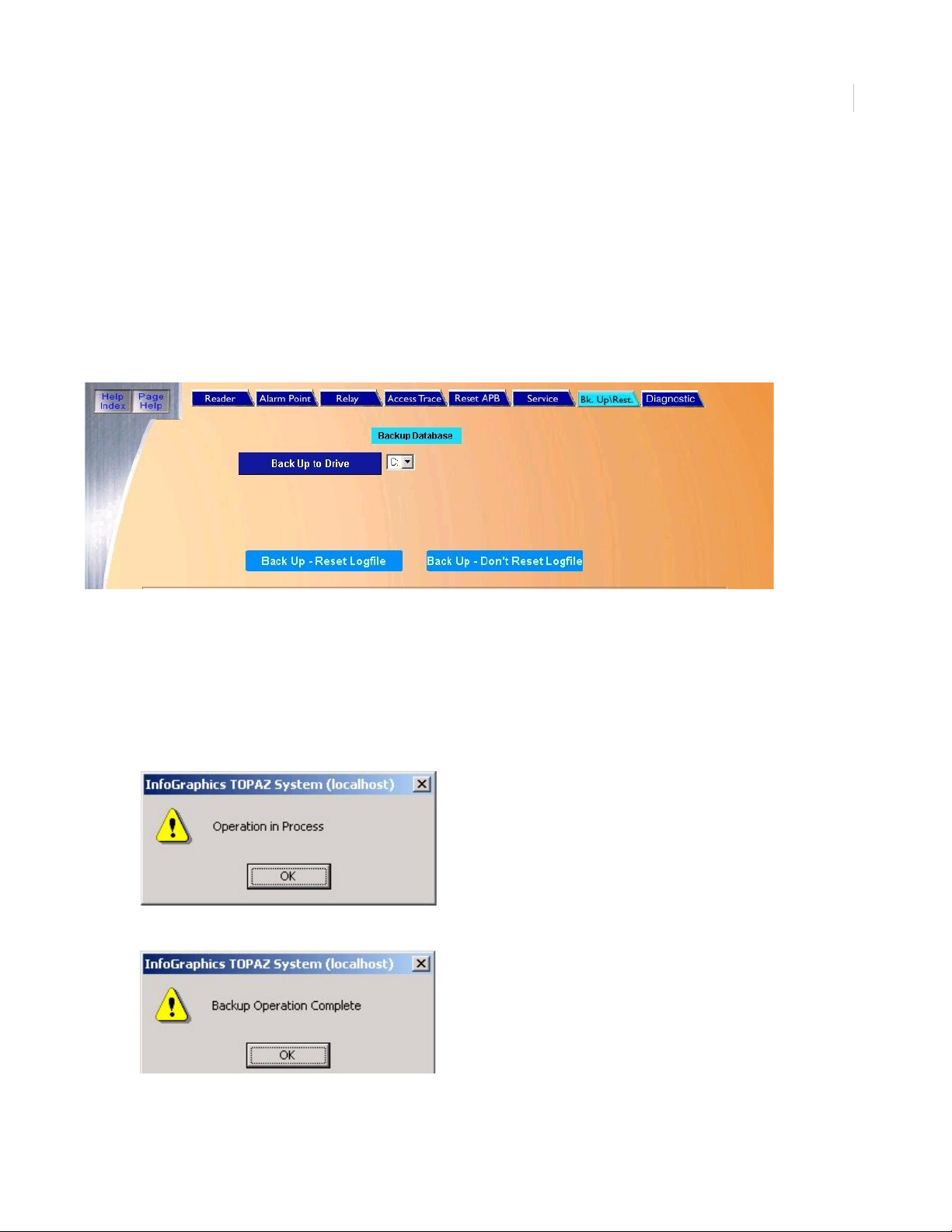
Chapter 1
Getting Started
Upgrading from Version 1.4.5 or earlier
Because versions before 1.4.6 used a different installer and a different default installation directory, it
is necessary to perform the following steps:
Note: Before starting Topaz make sure that “Microsoft Internet Explorer 6.0 provided by GE” has been installed using
the Topaz CD and the wizard has been run to complete the installation. If you have IE 6.0 already installed on your
computer, check if the title bar states “Microsoft Internet Explorer provided by GE”. If not, you must install the
Virtual Machine that is located on the CD. For more information, see Installing Virtual Machine on page 8.
1. Before installing the new software, perform a complete Backup of the system. Navigate to
the Control tab and select Back Up\Restore. The following page displays.
5
2. Select the Drive letter for the location where the files are to be backed up from the dropdown list of available drives. (C: E: F: etc.).
3. After the selection has been made, click Back Up - Don’t Reset Logfile to start the backup
process.
Note: We recommend when you backup the system for an upgrade, that you do NOT reset the log. This allows the
current log to be imported into the new 1.4.7 version of Topaz making past events available.
A window displays Operation in Process, indicating that the backup has begun.
4. Click OK
Page 24
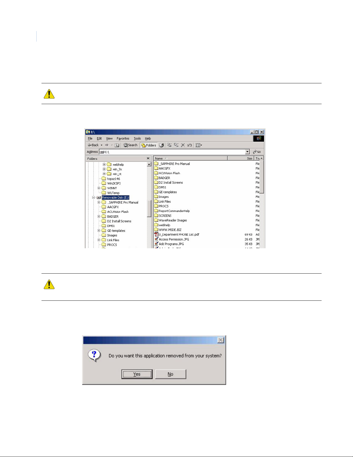
6
To pa z
User Manual
5. Once the backup is complete, the message “Backup Operation Complete” displays. Do not
log off or shut down Topaz until this message appears or the backup will be corrupted..
CAUTION: You must wait until the Backup Operation Complete dialog window displays before shutting down
Topaz. If you do not do this, the database will be corrupted and will not function.
6. Shut down Topaz and double-click the My Computer icon and browse to the location where
the backup was stored.
7. There should be five new folders: AACGFX, BADGER, DMS1, PROCS, and SCREENS.
These folders contain the backup. Delete the SCREENS folder and close this window.
CAUTION: You MUST delete the SCREENS folder. The SCREENS folder contains the old sysconfg.dat file. If this
folder is not deleted, when the database is imported into the updated version of Topaz, this older version will
overwrite the new sysconfg.dat and some features will not function.
8. To uninstall your existing version of Topaz, click the Start button and select Settings, then
Control Panel. When the Control Panel opens, double-click Add/Remove Programs.
9. Select Topaz and click the Change/Remove button.
Page 25
Chapter 1
Getting Started
10. Click Yes to confirm the removal of the older version of Topaz. When the program has been
removed, the following message displays.
11. Clic k Ok.
12. Insert the Topaz installation CD and install the new version of Topaz, as described in
Software Installation on page 8.
13. When the installation is complete, open Windows explorer or My Computer and navigate to
the folder:
C:\Program Files\GE\Topaz\Screens
14. Locate the file, sysconfig.dat, and move it to a temporary folder.
7
15. There are now two Topaz icons on your desktop. One of them is labeled Topaz the other one
is Topaz Server. From your desktop, double-click Topaz Server (not Topaz).
16. Log on as master.
17. Navigate to the Control tab and select Back Up/Restore.
18. Under Restore Database, select the drive letter C.
19. After the restore is complete, shut down Topaz and restart the computer.
20. After the computer is rebooted, log on to Windows explorer and remove the Topaz directory
from the C drive that was created in step 3.
21. Navigate to the temporary folder where you placed the file, sysconfig.dat, in step 14 and
replace it in the folder: C:\Program Files\GE\Topaz\Screens
22. From your desktop, double-click Topaz (not Topaz Server). Log on to Topaz using your
installer login and password.
Page 26

To pa z
8
User Manual
Software Installation
Before you Start Installing the Software
Note: Before starting Topaz make sure that “Microsoft Internet Explorer 6.0 provided by GE” has been installed using
the Topaz CD and the wizard has been run to complete the installation. If you have IE 6.0 already installed on your
computer, check if the title bar states “Microsoft Internet Explorer provided by GE”. If not, you must install the
Virtual Machine that is located on the CD. For more information see Installing Virtual Machine on page 8
Setup for Internet Explorer
1. From Window’s desktop, right-click the Internet Explorer Icon and select Properties. Do not
use a Short Cut Icon.
2. On the General tab, click Settings, select Every visit to the page, and click OK to save.
3. On the Connections tab, click LAN Settings and make sure Use a proxy server for your
LAN is NOT
unless a proxy is required. If a proxy is required, leave Use a proxy server for your LAN
checked, click Advanced..., and add the address of the Topaz server in the exceptions box.
selected. If it is selected, we recommend you uncheck the box and click OK,
4. On the Privacy tab, move the slide bar to Low, then click OK to save. Topaz uses session
cookies (no information is written to disk), which may also be enabled using the Privacy tab,
and clicking Advanced...
5. Click OK to save and exit Internet Explorer Properties.
This topic describes how to begin interacting with the Topaz System Software. The installation uses
default options.
The Auto configuration function may also be used to assist you in setting up the system.
Whenever possible power-up the system's peripheral devices before activating the server computer.
In this way, any errors or diagnostic messages display at the system's monitor or printer.
Note: If you use a workstation, the server should be running on the network before starting up the workstation.
The installation steps for a Server or Workstation are almost identical but are described separately.
The installation steps for a Server are described below.
The System Software comes on a CD (Compact Disk). The CD is used to load the Topaz application
onto the computer server and workstation.
If you are using Windows 2000 or XP, log on as the Administrator.
Installing Virtual Machine
The installer for virtual machine is located on the Topaz software CD.
1. Insert the CD and when the Install window opens, select Browse CD.
2. When the folders window displays, click the folder named IE6 to open it.
3. Locate the msjavx86.exe file and double-click the file name. The following install window
displays.
Page 27
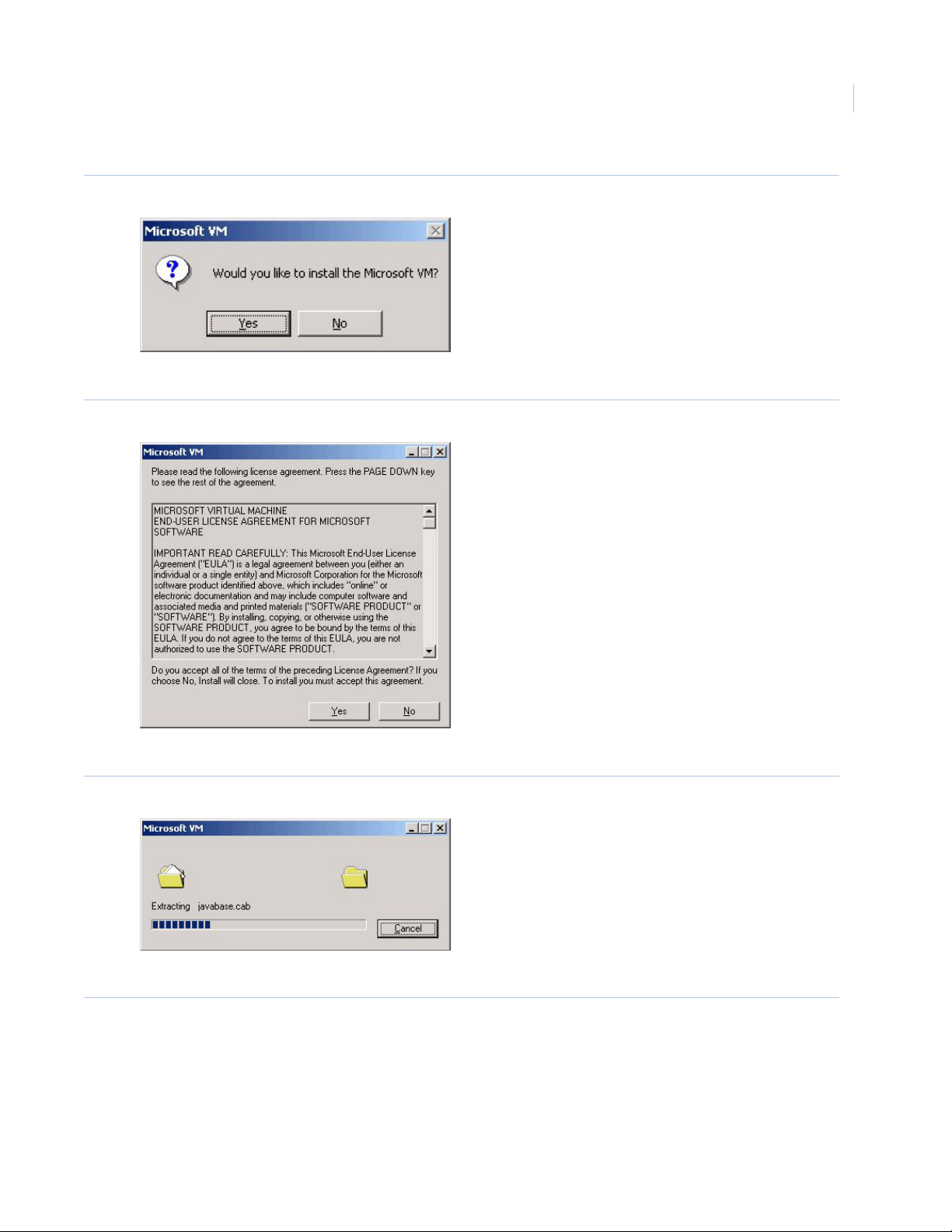
Figure 1. Microsoft VM
4. Click Yes. You do want to install the Virtual Machine.
Figure 2. Microsoft VM License Agreement
Chapter 1
Getting Started
9
5. Read the agreement and click Yes to begin the installation of the files.
Figure 3. Microsoft VM extracting
A progress bar shows the process of the installation.
Figure 4. Microsoft VM installation complete
Page 28
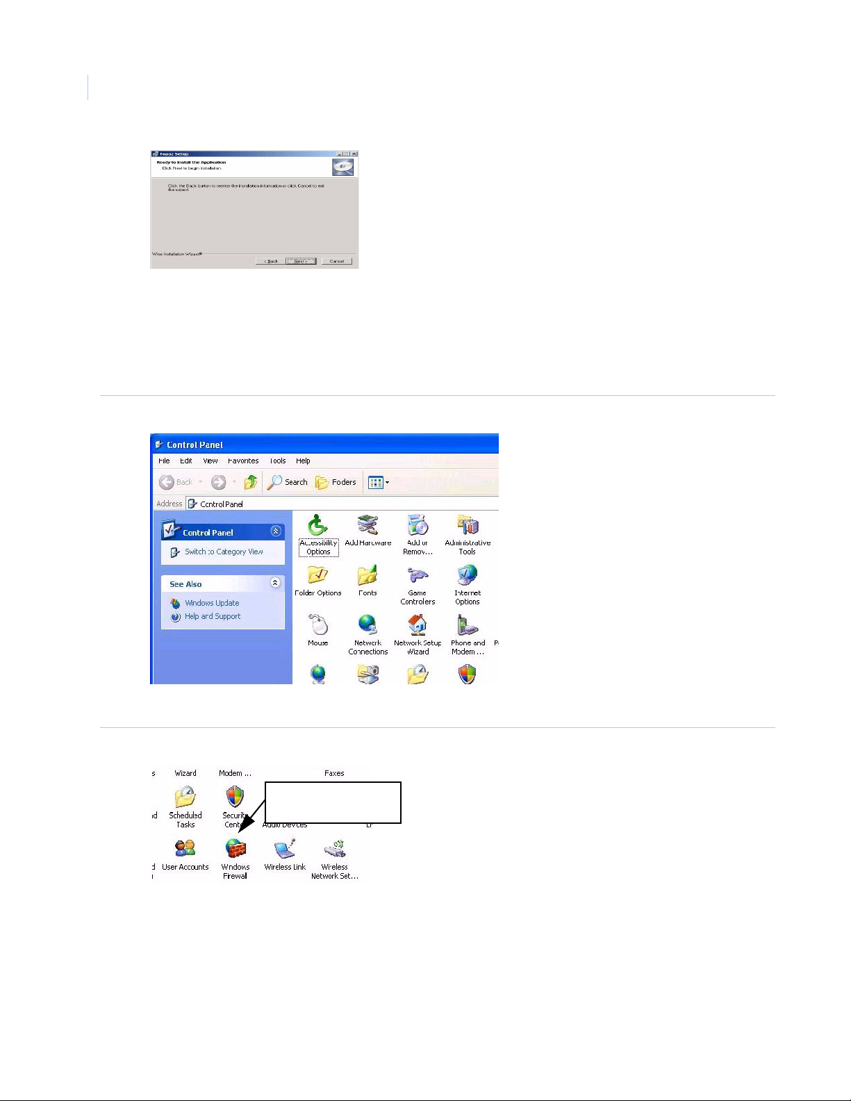
To pa z
Click this icon to open
the Firewall controls
10
User Manual
6. When “The installation is complete” message displays, click OK.
Setting XP sp2 Firewall
1. To open the Control Panel click Start > Settings > Control Panel
Figure 5. Control Panel
2. Double-click the Windows Firewall icon.
Figure 6. Windows Firewall
3. When Windows Firewall opens, click the Exceptions tab.
Page 29
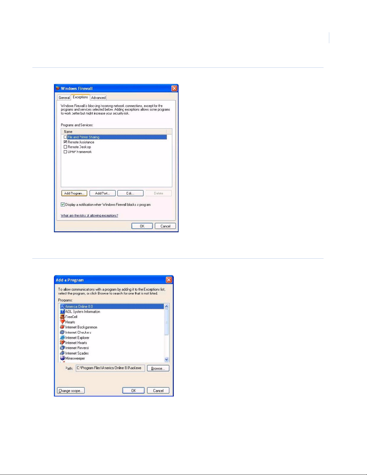
Figure 7. Exceptions tab
Chapter 1
Getting Started
11
4. Click Add Program to add two components of Topaz to the list of programs that may pass
through the Firewall.
Figure 8. Add Program
5. Using the Browse button, locate mp.exe. It is located in the folder where Topaz was
installed. The default location is C:\Program Files\GE\Topaz folder as shown below.
Page 30
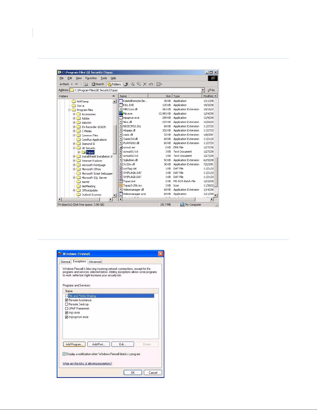
To pa z
12
User Manual
Figure 9. Default Topaz directory
6. Highlight mp.exe in the list and click Open to add it to the Add a Program window. Highlight
mp.exe in the Add a Program window and click OK.
7. Repeat steps 4. through 6. but this time add mpuprun.exe.
Figure 10.mpuprun.exe
Page 31

Chapter 1
Getting Started
8. The program now appears in the Programs and Services section of the Exceptions tab. Make
certain that the check box beside it contains a checkmark. Click OK to close the Firewall
properties.
Installing a Host PC Server
Note: The installation steps for a server are described below. The installation steps for a Workstation are described
under “Hardware”, then “Workstation”, and then “Add a Workstation” elsewhere in this manual.
Make sure you are logged in as the Administrator so you have the correct rights to install software.
Insert the Topaz Installation CD into the CD drive. If Auto Insert Notification is enabled for your CD
drive, the Install Menu provides a list as shown below.
If the Install Menu does not appear within one minute, follow this procedure:
1. Open Windows Explorer.
2. Double-click the drive letter for the CD drive.
3. In the root directory, double-click the file start.bat.
13
The Topaz Install screen displays.
Note: Before installing Topaz make sure that “Microsoft Internet Explorer 6.0 provided by GE” has been installed
using the Topaz CD and the wizard has been run to complete the installation. If you have IE 6.0 already installed
on your computer check if the title bar states “Microsoft Internet Explorer provided by GE”. If not, you must install
the Virtual Machine that is located on the CD. For more information see Installing Virtual Machine on page 8
Figure 11.Topaz Installation CD
1. Click Install Topaz to start the installation setup.
Page 32

To pa z
14
User Manual
Figure 12.Topaz files extracting
2. If this is the first time Topaz has been installed on your computer and the Microsoft .NET
Framework is not installed, the Wise Installation Wizard dialog window shown above
displays. Extracting and installing the .NET framework may take several minutes. Please wait
while the Hourglass progress icon rotates. When the framework is completed, the Topa z
Installation Wizard begins. If the .NET framework is already installed on your machine, it
proceeds directly to the Welcome to the Topaz Installation Wizard dialog window.
Figure 13.Topaz Setup: Installation Wizard
3. Click Next to continue.
Page 33

Figure 14.Topaz Setup: License Agreement
Chapter 1
Getting Started
15
The next window is the End User License Agreement. Read it then select I accept the
license agreement. The Next button becomes available once the agreement is accepted.
Click Next to continue.
Figure 15.Topaz Setup: User Information
4. The next window asks you to enter User Information. Type the name of the user in to the
Full Name field and the name of the organization into the Organization field. Select the radio
button beside Anyone who uses this computer. This is used to permit the system to
communicate with and respond to the Video Recorder. Click Next to continue.
Page 34

To pa z
16
User Manual
Figure 16.Topaz Setup: Destination Folder
This dialog window determines were the Topaz files are stored on the system. If you do
not want to use the default directory, you may follow this procedure:
a. Click the Browse button and the Browse for Folder window displays.
Figure 17.Browse for Folder
b. If you prefer to use a different directory, such as “Program Files”, select the desired
location for the Topaz software (such as c:\Program Files\Topaz) and click OK, then Next.
Page 35

Figure 18.Topaz Setup: Type of Installation
Chapter 1
Getting Started
17
5. This dialog window determines the type of installation. Are you installing the Server? Click the
radio button next to Topaz Server. Also consider whether remote workstations (those not
resident on the server computer itself) are used. If other computers are used as workstations,
click the radio button next to Yes, I want to add workstations. If you are installing a
workstation, select Topaz Workstation. For more information see How to install a workstation
on page 207.
Note: You must install Topaz on the server computer before installing it on any workstation computer.
Figure 19.Topaz Setup: Ready to Install the Application
6. If you satisfied with your settings, click Next to start installing the system.
Page 36

To pa z
18
User Manual
Figure 20.Topaz Setup: Updating System
The wizard uploads the required files and installs them onto the computer. During the
process, a progress bar displays.
Figure 21.Topaz Setup: Finish
7. When all files have been installed, the Topaz has been successfully installed dialog
window displays. Click Finish to continue with the installation of several video files. These
files are installed whether or not you are using Video.
Page 37

Figure 22.NVR Codec Installer
8. Click OK to install the Video files.
Figure 23.Warning
Chapter 1
Getting Started
19
Note: If a warning window displays that certain files already exist, click Yes to continue. When the dialog window asks
whether to replace all files with the same name without questions, click Yes.
Figure 24.Specify Directory
9. This dialog window appears if you selected Yes, I want to add workstations in step 5. Click
OK and another Browse window appears. Select where the Workstation.hta file should be
saved. This file is used when installing a workstation on another computer. Make certain that
the location selected is accessible by the workstation computers. After selecting the location
click OK.
Figure 25.Operation Complete
10. The dialog window indicates that the file was written successfully. Now wait a few seconds
and the Sentinel Driver installation wizard starts.
Page 38

To pa z
20
User Manual
Figure 26.Sentinel System Driver: Welcome
Note: If this is the first time you have installed Topaz on this computer, you should follow the remaining steps. If this is an
update, you may cancel out of the Sentinel Driver wizard.
11. Clic k Next to install the sentinel drivers.
Figure 27.Sentinel System Driver: Ready to Install
12. Remove all software sentinel keys from the USB port before continuing. Click Install to
continue.
Note: The USB software sentinel key is provided with the Topaz system when you order it. This dongle is required for
Topaz to work properly. If this is an upgrade, you may have a serial sentinel key. This will work and does not need
to be replaced with a USB dongle. It also does not need to be removed during this process.
Page 39

Figure 28.Sentinel System Driver: License Agreement
Chapter 1
Getting Started
21
13. Select I accept the terms in the license agreement, and the Next button becomes
available. Click Next to continue.
Figure 29.Sentinel System Driver: Setup Type
14. Select Complete, then Click Next to continue.
Page 40

To pa z
22
User Manual
Figure 30.Sentinel System Driver: Ready to Install
15. Remove USB sentinel keys before continuing, then Click Install. A screen with a progress
bar displays while the Sentinel Driver files are installed.
Figure 31.Sentinel System Driver: Install Completed
16. Click Finish.
17. You are now returned to the desktop and the following message displays.
Page 41

Getting Started
Figure 32.Warning
18. You must restart your PC for the Topaz software to be activated. Click Yes to reboot your
system.
This ends the installation steps for a server. To add a workstation, see Workstation Page on
page 204.
To start Topaz, double-click the Topaz icon on your desktop.
Chapter 1
23
Page 42

24
To pa z
User Manual
Page 43

Chapter 2 Using Topaz
This chapter describes how to begin using the Topaz system software. The
installation uses default options so you do not have to make decisions or
selections.
In this chapter:
Start Up. . . . . . . . . . . . . . . . . . . . . . . . . . . . . . . . . . . . . . . . . . . . 26
Help . . . . . . . . . . . . . . . . . . . . . . . . . . . . . . . . . . . . . . . . . . . . . . 26
Startup, Log-on, & Navigating. . . . . . . . . . . . . . . . . . . . . . . . . . . 28
Page 44

To pa z
26
User Manual
Start Up
Note: Before starting Topaz, make sure Internet Explorer 6.0 or later was installed from the Topaz CD and the wizard
was run to complete the installation of IE, or Topaz will not operate properly.
The Auto configuration function may also be used to assist you in setting up the system.
Whenever possible, power-up the system's peripheral devices (field panels, readers, etc.) before
activating the server computer. In this way, any errors or diagnostic messages display at the
system's monitor or printer.
Note: If you use a workstation, the server should be running on the network before starting up the workstation.
Help
A major feature of Topaz is its Help section. Help is designed to assist you in real time on any part of
Topaz operations. This enhancement reduces your need to refer to written documentation and
reduces training time for new users.
Two Help buttons are located in the top left corner of each of the browser pages.
• Help Index - This button opens a content sub-window that enables you to locate topics from
the whole Help system by using the Table of Contents, Index, or Search functions.
• Page Help - This button opens a content sub-window that enables you to easily locate topics
covered on the currently selected browser window only. However, while using the Page Help
you may also click the Word SHOW button in the top left corner of the help page. This opens
the Global Help as a sub-window on the left side of the help page allowing you to access all
Help topics.
Navigating the Help Table of Contents
The Table of Contents structure follows the navigation hierarchy of Topaz. On the left side, the Table
of Contents displays.
Each closed book represents a branch of the tree, such as .
When you move the pointer over a book title, it underlines the Title. Clicking on the underlined title to
the right of the Book, opens that Book to display Pages (such as Cardholder Database Reports) in
the Book, and possibly more Books, as shown below:
You can click a Page, such as Recall All Events to go to the Recall All Events
Help page, as shown below:
Page 45

Figure 33.Sample Help page
Chapter 2
Using Topaz
27
Page 46

To pa z
28
User Manual
Startup, Log-on, & Navigating
Startup
After the Topaz software has been properly installed, double-click the Topaz icon on the Windows
desktop to startup the Topaz program.
After a brief initialization period, the log-on window shown below appears on your computer screen.
Log-on Window
Following the System initialization, the Workstation Log-on Window fills the monitor.
Figure 34.Workstation Log on window
To log-on to Topaz, place the mouse pointer in the box labeled Operator ID, click, and type your
Operator ID. Then move the pointer to the box labeled Password. Click and type your password.
Note: If this is a new system you may use the default Operator ID of “master” with no password. Neither the Operator ID
nor the Password is case sensitive. You may change the default password by following the procedures in the
section Operators Setup Page on page 161.
Page 47

Chapter 2
Using Topaz
Now, click Enter to complete your log-on to the Topaz System.
Starting Topaz the First Time Topaz is Started
The following applies only if you are using the Topaz Software for the first time. If this is not the first
time, and you wish to use Auto Configuration, see Auto Configuration Setup Page on page 252.
After clicking Enter, the following message displays.
Figure 35.Auto configuration
29
To have Topaz automatically configure the software and hardware, click OK. For more details see
Topaz Quick Start on page 30 and Auto Configuration on page 31.
If you do not wish to auto configure your system, click Cancel and the standard workstation browser
navigation page displays as shown in Server/Workstation Display on page 35.
Page 48

To pa z
30
User Manual
Topaz Quick Start
When you startup Topaz, the QuickStart displays as shown below.
Figure 36.Topaz QuickStart
QuickStart consists of seven (7) pages of information on the Topaz System and how to get it set up
easily and quickly.
QuickStart stays active in the foreground even if you click a button to access a Topaz screen. To see
more of the background Topaz screen, click and drag the QuickStart page by the menu bar (at the
top). You may also “minimize” QuickStart by clicking on its minimize button in the upper right corner
of the QuickStart window, or click anywhere outside of the QuickStart window. Once minimized, you
can open QuickStart at any time by clicking on the QuickStart button in the Navigation Bar in the left
side of the main Topaz window.
You can navigate through QuickStart by:
• Click the underlined links.
• Use the scrollbar on the right of the window.
• Click the Next Page >>
and << Previous page links.
To close QuickStart, click the in the upper right corner of the QuickStart window or click the Click
here link.
You can open QuickStart at any time by clicking on the QuickStart button in the Navigation Bar in the
left side of the main Topaz window.
Page 49

Chapter 2
Using Topaz
All Topaz buttons in the QuickStart may also be clicked to access that part of the Topaz software.
Subjects covered in the QuickStart are:
• Programming Guide
• Auto Configuration
• Batch Card Entry
• Suggested System Setup Flow Chart
•Setup
• Hardware
• Cards
• Other menus you should become familiar with
• An Introduction to the Topaz Access Control System
Auto Configuration
Auto Configuration is a unique software feature that automates the systems setup of hardware and
cardholder programming efforts. All the installer or end-user needs to do is log-on, and Topaz
automatically detects and defines all field devices connected to each port on the computer. Topaz
also defines a default value for all device, system and cardholder data. Such pre-defined and preconfigured data includes the creation of basic reader access groups, time intervals, time schedule,
holidays, activation date, cardholder access group assignment, reader, alarm point defaults, default
alarm definitions, and alarm message text, as well as the physical hardware hierarchy and its
graphical “tree” representation.
31
The Topaz software initiates polling on demand by user command as described below, of the file
server's maximum five (5) serial communication ports and one (1) LAN port. It records an inventory
of all port communication interfaces (that is, serial card, modem, LAN card, and CCTV switcher) and
all their downstream “devices” (for example, ACUs, Readers, Alarm Points, Relay Outputs, System
Alarms [device off-line, tamper, battery low], Workstation, and CCTV Switch).
Initiation of the Auto Configuration Feature
You can start Auto Configuration by either of the following ways:
• If this is a new Topaz installation, without any communication ports or hardware devices
configured, and you click the Topaz desktop icon to start Topaz, and then enter your log-on id
and password, Auto Configuration starts automatically. You must have the proper password,
since access to Auto Configuration is password protected.
Note: You must start Topaz from the desktop icon. Logging off and logging back on again does not start Auto
Configuration.
If you are using dialup or a LAN connection, some manual configuration is required, such as the LAN IP address,
or phone number.
Once you configure a port or device, Auto Configuration no longer starts automatically.
However, you can still run Auto Configuration manually by the next method.
• If you are running Topaz and have the appropriate permissions, you can click the Hardware
button on the left and then the Auto Configuration button on the menu on the right.
Page 50

To pa z
32
User Manual
An Auto Configuration sequence may also be initiated from the Auto Configuration Home screen for
any or all selected devices listed in both the “Configured” and “Not Found” boxes.
Starting Auto Configuration displays the following dialog box:
If you select Cancel, you may continue with manual programming of the system. If you select OK,
the following message displays along with an hourglass in place of the mouse pointer:
Click OK to continue.
Topaz starts the Auto Configuration process to detect and configure the hardware. The process may
take a few minutes. If you have COM ports, the following message displays:
Click OK to continue.
You may click to select one or more ports you wish to Auto Configure. You may de-select highlighted
ports by clicking the Clear button or you may leave this page without further changes being recorded
by clicking on any of the buttons in the main tool bar on the left side of the screen.
Once you have selected the ports, press the Configure button, the system performs an automatic
configuration to find new devices or changes to the system on those highlighted ports.
The message “Operation Complete” displays. Click OK to continue.
The left side of the screen displays devices that have been either: (1) detected as physically
connected to the server, but have not been programmed/configured or, (2) they have been
programmed but are currently not connected.
The Auto Configuration Home screen displays the entire network of field devices: found-andconfigured, found-and-not-configured, and configured-but-not-found. On the right side of the screen,
all devices are displayed in a dynamic “Tree” formation, with Graphical Icon representations of the
Page 51

Chapter 2
Using Topaz
various device types (for example, workstation, ACU, reader, alarm point, CCTV switch, and relay
output), and with the following text description colors:
Found - not Configured Green
Connected - not Found Red
Found and Configured Black
The following is an example of what an Auto Configuration screen might look like:
Figure 37.Sample Auto Configuration screen
33
Page 52

To pa z
34
User Manual
Default Device Names
After Auto Configuration has been completed, the devices have numeric names, for example,
Reader 2-1-3 is Host Port two (2), Field Panel address one (1), Reader number three (3). You may
want to rename the devices with your own descriptive names. For more detailed information see the
chart below.
Table 1. Default Device Names
Example Typ e COM # ACU Polling # Reader/Alarm# Alarm Type
Field Panel
Reader
Reader Alarm
Alarm
Area
Panel Alarms
Input Module
Output Module
Device 1-0 Device 1 0
RDR 1-0-0 RDR 1 0 0
RDR 1-0-0 FO RDR 1 0 0 FO (Forced Open)
Alarm 1-0-0 Alarm 1 0 0
Area 1-0-0 Area 1 0 0
Example Type Device # Remote Module Port # Address Alarm Type
ACU 1 -TAMPER ACU 1 TAMPER
RIM 1-1-7-OL RIM 1 1 7 OL (Offline)
RRM 1-1-5-OL RRM 1 1 5 OL (Offline)
For more details on Auto Configuration see Auto Configuration Setup Page on page 252.
Note: Aside from auto configuring your system and specifically for day-to-day system hardware navigation and editing,
Topaz incorporates a separate device tree page. At any time you can click the Device Tree button in the main tool
bar to navigate to the stand-alone device tree.
Device Tree
The Device Tree is a dynamic “Tree” representation of the entire system’s hardware, from the
server’s communication ports, to all field hardware including workstation field panels (ACURT2/RT4).
Page 53

Server/Workstation Display
Figure 38.Browser navigation page
Chapter 2
Using Topaz
35
The Topaz interface (shown above) is divided into 3 sections: Main Browser Window on page 44,
System Navigation Menu on page 36, and the Alt Menu on page 37.
Page 54

To pa z
36
User Manual
System Navigation Menu
Topaz’s Main Navigation Menu is on the left side of the main
Operator Screen. Use the mouse pointer to click the icons or
buttons to navigate through the system. The main navigation
buttons on the left of the Operator Screen and the Alarm Queue
window at the bottom of the screen are available at all times
while any page of the Topaz software displays.
The Alt Menu button displays the System Navigation Menu in a
multiple level (tree) format. See Alt Menu on page 37.
The Device Tree button displays the device tree at any time.
See Device Tree on page 257.
The Quick Start button calls up the quick start page to give you
a short overview of the system. See Topaz Quick Start on
page 30.
Page 55

Chapter 2
Using Topaz
Alt Menu
Click the Alt Menu button to view the System Navigation Menu in a multiple level (tree) format.
37
Press the ‘+’ button to expand the branch you want to view. Then, click on the page name (for
example, ‘Photo’) to bring up the ‘Employee Card Photo’ page in the main portion of the window.
Click on the ‘-’ button to collapse a branch of the menu. Selecting another branch's ‘+’ sign also
collapses a viewed branch.
Alarm Queue Window
The Alarm Queue window at the bottom of the main Operator Screen is shown below.
Page 56

To pa z
38
User Manual
The Alarm Queue window displays alarms as they occur in RED. The color of the text for the alarm
shows its status. The table below defines the meaning of the colors.
Table 2. Alarm Queue window colors
Color Status
Red Device in alarm
Green Secure
Orange An access event, for example, access denied
Purple Trouble condition (short circuit, circuit fault, etc.)
If there are currently more events in the queue than can be shown in the window at one time, a
scrollbar appears at the right side of the window. The scrollbar allows you to scroll through all alarm
events in the queue.
To remove an alarm from the queue, you must first acknowledge it and then clear it, as described
below.
If you have the Video Option, the alarm event has the word video in the information text. When you
select an alarm with video, the Video button becomes available to the left of the queue.
Figure 39.Alarm Queue window
When an alarm is activated, video is recorded and the clip is linked to that alarm event. As long as
the alarm point remains active, this is the only video clip that is linked to that alarm event. If the alarm
point is secured but has not been cleared from the queue, and an second event activates the same
alarm point, the new alarm event produces a new video clip of the second triggering event. However,
if the alarm has not been cleared from the Alarm Queue, the only video that can be viewed from the
alarm queue is the first video associated with that alarm point. The later video clips have to be
accessed from the Event Queue. See Video Option on page 49
For any alarm in the queue that is linked to the Color Graphics MAP feature, you can triple-click that
alarm or click MAP to bring up the Color Graphics map assigned to it. For more details on Color
Graphics, see Color Graphics Maps on page 295.
Acknowledging an Alarm Event
To acknowledge an Alarm event, click the text of the alarm to be acknowledged so it is highlighted.
Click ACK and the Alarm Details page shown below displays. The alarm sound continues until all
alarms in the queue have been acknowledged.
Page 57

Figure 40.Alarm Details
Chapter 2
Using Topaz
39
The Alarm Details page contains the following information.
Current State The state of the alarm.
Priority The priority assigned to the alarm during alarm point setup.
Alarm Type The alarm type assigned to the alarm during alarm point setup.
Description The description assigned to the alarm during alarm point setup.
Instructions The instruction message text assigned during Alarm Option Instructions setup.
Acked By The name of the operator logged on to the system when the event was
acknowledged.
Alarm Name The name assigned to the alarm during alarm point setup.
Date/Time The date and time the alarm event occurred.
Device Name The name assigned to ACU field panel the point is attached to.
Area The area assigned to the alarm during alarm point setup.
Comments Comments typed in by the operator (optional).
Click ACK to acknowledge the alarm. The name of the operator currently logged on to the system is
recorded in the Acked By field.
Note: The only field on the Alarm Detail page that can be changed or entered at anytime is Comments.
To close the Alarm Details window, click the X in the upper right corner of the window.
Page 58

To pa z
40
User Manual
Alarm Details Page Auto Display
To stop the Alarm Details page from automatically displaying, right-click anywhere inside the alarm
queue window and the following message displays.
Figure 41.Disable alarm details window
Click OK to stop the auto display feature.
Each time you now acknowledge an alarm, the color of the text changes to indicate that the alarm
has been acknowledged, but the alarm details page is not displayed.
You can still call up the Alarm Details page by clicking Detail or by double-clicking on the text of the
alarm inside the alarm queue window.
To start the Alarm Details page automatic display again, right-click anywhere inside the alarm queue
window and the following message displays.
Figure 42.Enable alarm details window
Click OK and the Alarm Details page again automatically displays each time you acknowledge an
alarm.
Color Graphics Not Ready Message
If you click MAP or triple-click an alarm in the Alarm Queue Window, which is linked to Color
Graphics, the Color Graphics map is displayed. For more details on Color Graphics, see Color
Graphics Maps on page 295.
If you do not see a MAP button, Color Graphics has not been configured for the workstation. To
enable Color Graphics:
1. Click Hardware on the left side of the main screen.
2. Select Workstation.
3. Under Workstation, select the name of your workstation. The name should appear in the
Workstation Name field.
4. Select Alarm Graphics by clicking in the check box.
5. Click Save/Add.
6. Click Refresh Alarm Queue to show the MAP button.
Page 59

Chapter 2
Using Topaz
Now you can click once to select an alarm event in the Alarm Queue Window, double-click to call
up the alarm details, or click MAP (or triple-click the alarm text) to call up the alarm color graphics.
41
If you have Color Graphics active but do not
queue window, make sure you do not triple-click
want to bring it up, when you select an alarm in the
the alarm.
Access Events
Access events are also logged in the Alarm Queue Window, for example, when access is denied.
To see more details on an access event, double-click anywhere on the access event in the Alarm
Queue window. The Access Details page displays as shown below.
Figure 43.Access Events Details page
Page 60

To pa z
42
User Manual
The Access Details page contains the following information.
Message The message assigned to the event during Reader Event setup.
Description The description assigned to the reader during Reader setup.
Badge Number The whole badge number, including company code, facility code, and card number
assigned to the cardholder.
Cardholder NameThe name of the cardholder assigned to the badge during Cards setup.
Instructions The instruction message text assigned during Alarm Point Option setup.
Reader Name The name of the reader used for this access event by the cardholder, assigned to
the reader during Reader setup.
Date/Time The date and time the access event occurred.
Device Name The name assigned to ACU field panel to which the reader is attached.
Area The name assigned to the security area under Security Area setup.
Acked By The name of the operator logged on to the system when the alarm was
acknowledged.
Comments Comments by the operator (optional).
Note: The only field on the Access Detail page that can be changed or entered at anytime is Comments.
To close the Access Details window, click the X in the upper right corner of the window.
Alarm Control Buttons
ACK The Acknowledge button is used to acknowledge the alarm. Select the alarm in
the alarm queue and click the button. The name of the operator currently logged
on to the system is recorded in the Acked By field.
CLEAR Alarm EventThe CLEAR button allows the operator to clear alarms. After an acknowledged
alarm has returned to normal condition, the color of the text turns to green and
the event may be cleared from the Alarm Queue window. To clear an alarm from
the Alarm Queue window, click the alarm to highlight it and then click the
CLEAR button.
DETAIL The DETAIL button displays a sub window with the details for the alarm that is
currently selected in the Alarm Queue.
MAP
The MAP button allows you to call up the available maps for alarms. However,
to access this Map feature, under Hardware – Workstation, you must have
Alarm Graphics selected. For more details see Color Graphics Maps on
page 295.
Page 61

Chapter 2
Using Topaz
Video The Video button allows you to call up the camera that was linked to the alarm
event that is highlighted in the alarm queue. Click the Video button and the
Video window displays as shown below.
When you click View Event, the window changes to the clip of the event. This
shows the alarm event starting at the moment the alarm occurred. To see the
moments leading up to the alarm click Reverse. See Video Option on page 49
for more information and an example of a Video Clip window.
Note: There may be a delay of 30-40 seconds after an alarm event occurs before the clip
becomes available by clicking View Event. Click the button once and the clip begins as
soon as it is available.
If you want to print a picture of the live feed, click Print.
To resume watching the live feed click Start.
43
To Return to the Live Video feed, click View Live and the live video screen
returns.
Page 62

To pa z
44
User Manual
System Control Buttons
These four buttons are located above the alarm queue below the main screen area.
REFRESH ALARM
QUEUE
When this button is clicked, the alarm queue is “refreshed” or “repainted”,
to re-display the image. If active alarms disappear from the queue, click
this button to retrieve them.
LOG OFF When this button is clicked, you are logged off the system. Before you can
take any further action on the Topaz system, you must first log back in with
a valid Operator ID and Password.
REFRESH MAIN FRAME When this button is clicked, the current main screen is “refreshed” or
“repainted”, to re-display the image.
TOPAZ SHUTDOWN When this button is clicked, the following message displays:
If you wish to continue shutting down the Topaz application, click OK.
Topaz shuts down and exits to the Windows desktop.
Note: If you are working at a Topaz workstation, the TOPAZ SHUTDOWN button only
stops the local software application. It does not shutdown the server. If you want
to stop the server, click this button on the Server machine.
Main Browser Window
The third section of the Main browser page is the larger portion of the
screen as shown in part on the left.
The main portion of the Main browser page has a set of silver
navigation buttons that duplicate the Main System navigation buttons at
the left side of the screen. As you move the mouse pointer over the
buttons, they change color slightly. If the left button is clicked while the
button is changed, it navigates to that section of the Topaz System.
You may use either set of buttons to navigate to the selected section of
the Topaz system.
Page 63

Chapter 2
Using Topaz
Navigating Sections of the System
Topaz has 7 basic navigation sections:
•Events
• Cardholder
• Control
•Status
• Reports
•Setup
• Hardware
Each browser page is an independent area. A frame is a section of a browser page. What happens in
one frame may or may not affect the information in another. The frames are different sizes. If more
information is available than can be displayed in the frame, scrollbars appear at the right side or the
bottom of the frame. Scroll up and down or left to right with the bar(s) to display all information.
Navigation Bar Structure
45
Topaz is a browser-based system, enabling you to use the mouse pointer to click icon buttons to
navigate through the system. You can click one of the buttons, or on any of the main buttons
on the left side of the navigation bar, to access any of the main sections of the software.
Tab Buttons
At times additional pages are made available by clicking the tab buttons from the navigation toolbar
at the top of each page, as shown below for Setup - Time Sched.
At times additional tab buttons appear after clicking on one of the top-level buttons in the navigation
bar, as shown below for Alarm Options, to show Instructions and Categories:
The main navigation buttons on the left of the screen and in the Alarm Queue window at the bottom
of the screen are available at all times while any page of Topaz is selected.
Page 64

To pa z
46
User Manual
Shutting Down the Software
The following is the recommended method to shut down the software and its peripheral devices. To
prevent loss of data, follow these procedures in the order listed. If your system includes optional
hardware, refer to the equipment's documentation and follow the manufacturer’s instructions.
CAUTION: Once you have shut down the Topaz workstation, all on-line processing stops at the workstation. If the
Topaz Server is powered down, it will not enunciate any alarm reports or access requests. Depending on your
current security hardware, access control decisions may then be handled by the controller (ACU) in the field.
You should have a contingency plan in effect to monitor alarms manually while the Topaz Server is off-line. You
must take whatever precautions necessary to protect the safety of the personnel and equipment in your facility.
Procedure
1. Start from any Topaz System page.
2. Click TOPAZ SHUTDOWN in the bottom right corner of the screen. The message “Are you
sure that you want to shut down the system?” displays. Click OK.
3. The Topaz System program closes and returns to the Windows desktop.
At this point you can start another application or continue to shut down the Windows operating
system in the recommended manner.
CAUTION: Shutting down the Topaz program at the server terminates all communications to the field devices.
Alarms and events will no longer report to the server until the program is restarted and a download is initiated.
Although the alarms and events are stored at the local field panel (ACU) until the server is back on-line, the
amount of data stored is determined by the on-board memory of these devices.
Page 65

Chapter 3 Events
The Events page lists all event that occur in the system. This includes
everything from successful or failed startup processes to alarms.
In this chapter:
Events Page . . . . . . . . . . . . . . . . . . . . . . . . . . . . . . . . . . . . . . . . 48
Page 66

To pa z
Video Clip
Button
48
User Manual
Events Page
The Events page is opened as an independent browser page that appears as an overlay onto the
existing browser page.
Figure 44.Events page
This Events window shows all system events (alarm, system, device, and access events) as they
occur. An event contains information that the system's server records to its database. Each event is
given a sequential event number and a description. However, depending on how event processing is
set up, not all events are displayed and some event numbers appear to be skipped over.
To close the Events window click the X in the right top corner of the window to return to the existing
Main System browser.
The system updates this window constantly, but for the most part you will not see the status change
in this window often, unless there are new events.
If the video option is activated, this page may also contain events that are linked to a video clip. The
video clip can be accessed by opening the Detailed Event Window
Detailed Event Window
More details of each event can be instantly displayed by clicking on the event text inside the queue.
A Detailed Event window displays in a pop-up window. This contains further details of the event.
When finished with the Detailed Event window, click the X in the upper right corner of the window to
close it.
Figure 45.Detailed Event window.
Page 67

Chapter 3
Events
Video Option
If the event has a Video Clip associated with it, the Video button (shown above) appears. To access
the video clip, click Video. The Video opens in another window and plays the clip. The clip begins to
play ten (10) seconds before the point where the event was began. To see what happened before the
event, click Reverse to play the clip backwards.
Figure 46.Video clip
49
The control buttons are similar to those on a DVR:
Fast Reverse
Play in Reverse
Pause
Play Forward
Fast Forward
Page 68

To pa z
50
User Manual
If you have found a frame of an event that you want to print, click Print. The image is printed on the
Report Printer.
To see what is happening at the camera that recorded the event clip, click View Live.
When you have finished viewing the video clip, click Close Window to return to the Event Details
window.
CAUTION: Do not close this window using the X in the upper corner. This can cause Topaz to lose communication
with the video. Always click the Close Window button to close the window.
Page 69

Chapter 4 Cards
The Cards page allows you to add Cardholders and configure their access
privileges or photo ID.
In this chapter:
Cards . . . . . . . . . . . . . . . . . . . . . . . . . . . . . . . . . . . . . . . . . . . . . 52
Card Setup Page . . . . . . . . . . . . . . . . . . . . . . . . . . . . . . . . . . . . 53
Access Page. . . . . . . . . . . . . . . . . . . . . . . . . . . . . . . . . . . . . . . . 57
Photo ID Page . . . . . . . . . . . . . . . . . . . . . . . . . . . . . . . . . . . . . . 60
Masking Page. . . . . . . . . . . . . . . . . . . . . . . . . . . . . . . . . . . . . . . 65
Information Page . . . . . . . . . . . . . . . . . . . . . . . . . . . . . . . . . . . . 68
Custom Fields Page . . . . . . . . . . . . . . . . . . . . . . . . . . . . . . . . . . 69
Batch Add Page . . . . . . . . . . . . . . . . . . . . . . . . . . . . . . . . . . . . . 70
Batch Delete Page . . . . . . . . . . . . . . . . . . . . . . . . . . . . . . . . . . . 73
Page 70

To pa z
52
User Manual
Cards
The Cards button navigates to the following pages, allowing you to add Cardholders and configure
their Access Privileges, Photo ID, etc.
Card Setup Page on page 53
Access Page on page 57
Photo ID Page on page 60
Masking Page on page 65
Information Page on page 68
Custom Fields Page on page 69
These functions are accessed through the navigation bar buttons at the top of the Cards page.
To navigate to the Cards pages, click the Cards button on the left side of the browser window. The
following page displays.
Figure 47.Cards.
You can select a function to view or edit by clicking on the button at the top of the window.
The Cardholder Search window on the right continues to be displayed while navigating through the
Cardholder button pages. The only window that changes when the navigation buttons at the top are
selected is the area in the center of the screen.
Page 71

Card Setup Page
The Card Setup page allows you to add, recall, modify or delete cardholders.
Figure 48.Cards: Card Setup
Chapter 4
Cards
53
The Card Setup page contains the following information.
Cardholder Name Enter the Cardholder Name of up to 12 of characters for “First” name, 1 character for “MI” (not
required), and 15 characters for “Last” name. The Cardholder Name is a required field.
Note: You must know the encoded number of the card including the company and facility codes
before continuing. The number is listed on a document which was included with the card
when shipped, unless you requested custom cards with the card number printed on the
back of the card.
Card Number Enter the Card Number of up to 10 digits. The Card Number is a required field
Note: The Card Number is the only field that may NOT be repeated for the same Facility
(Company Code plus Facility Code). You can have two identical Card Numbers as long as
the Facilities are different.
Facility Code Select the Facility Code by clicking on the down arrow and selecting from the list of Facility Codes.
To configure a Facility Code, click the link arrow to the left of the field to open the Facility Code
configuration page. When you have completed the configuration, close the page by clicking Save.
Employee Number This field is optional and can be a maximum of 12 alphanumeric characters.
Card Stamp Number This is optional and can be a maximum of 8 numeric characters. The number is printed on the back
of the card. If you request it, the number is also the card number (and the encoded card number).
However, to be used as the Card Number, the Card Stamp Number must be entered into the Card
Number field.
.
Page 72

To pa z
54
User Manual
Card Status The Card Status defaults to Valid, meaning that the card is a usable card in the system.
Click on the down arrow to select other options:
• Lost (card is denied access)
• Stolen (card is denied access)
• Inactive (card is denied access)
• Terminated (card is denied access)
The status of these options indicates to the system that the card is not valid and to deny access
under any circumstances.
Issue Level The Issue Level only applies to magnetic stripe cards and is the number of times this card number
has been issued (given to a single Employee). A card may be reissued if the Employee reported his
or her card lost or stolen. Click the down arrow and select from the list of forty-nine (49) issue levels.
Save/Add Click to save the cardholder information to the database.
After clicking Save, one of three messages appears.
• If “Operation Complete” displays, no further changes are needed.
• If “Duplicate Record” displays, then the Card Number has been repeated. Use a new Card
Number and try saving again.
• If “Operation Failed” displays, then a required field was not entered (Card Number or other
field). Enter the required information and try saving again.
Note: If Photo Badging is being used, once the picture of the employee is added on the Photo ID
page, it displays in the top right corner of the page.
Clear At any point, if you wish to clear the entered information, click Clear.
CAUTION: Clicking Clear before clicking Save deletes newly entered data.
How to add a new cardholder
1. Click Clear to clear any existing data from the fields.
2. Enter the information on the Card Setup page for the new cardholder.
3. Once all data for the new cardholder has been entered, click Save/Add. The message,
“Operation Complete” displays.
How to recall a cardholder
There are five ways to recall a cardholder in the database. The default is by Name. You can select a
different filter by moving the mouse pointer to the Search by button. The drop-down list displays
allowing you to select one of four (4) other options. As the mouse pointer is moved over the search
fields, they change color. When the desired field is highlighted, click the left mouse button to select it.
Recall By: • Name (default)
• Card Number
• Serial Number
• Employee Number
• Vehicle License
Page 73

Recall by Name
• In the Enter Cardholder window, as you start typing the name of the cardholder, the list
highlights the name in the list. For example, if “m” is typed, then “Martin, Jean” is highlighted
in the scrolling Select Cardholder window. If this is the cardholder you are looking for, click
the highlighted name in the Select Cardholder window. The data window fills in with Jean
Martin's data.
Chapter 4
Cards
55
• You may also scroll through the Select Cardholder list in the window. When the desired
cardholder name is located, click the name of the cardholder. The data window fills in with the
cardholder's data that you just clicked on.
Page 74

To pa z
56
User Manual
• At the bottom of the Select Cardholder window the Record Last Changed indicates the last
date any changes or modifications were made to the current cardholder record being
displayed.
Note: It may be necessary to use the scrollbar on the right side of the cardholder page to move the window up to show
the Record Last Changed date.
Using the other Search By filters
1. Select [filter] that you want to use from the Search By button.
2. The Select Cardholder window now contains all cards in the system with the [selected filter]
information displayed.
3. Begin typing the first digits of the desired information and the first card matching the typed
information is highlighted. When the correct card is highlighted, click the highlighted card.
The employee information fills the page.
Note: When searching by Serial Number, the numbers that appear in the Select Cardholder field are the numbers that
were entered in the Card Stamp Number field on the Cards>Setup page.
How to modify a cardholder
1. Follow the Recall Cardholder procedure to recall a cardholder record to be modified.
2. Make the desired changes to any field except the card number.
3. Once all changes for the cardholder have been made, click Save/Add. The message
“Operation Complete” appears.
How to delete a cardholder
1. Locate the cardholder to delete.
2. Once the cardholder record is found and the database record is displayed, click Delete.
3. A message “Are you sure that you want to delete this record?” displays. Click OK to continue.
4. The message “Operation Complete” should be displayed indicating that the cardholder has
been deleted from the database.
5. The cardholder's record is now deleted from the database and the cardholder's name has
been removed from the Selected Cardholder list on the right side of the screen.
Page 75

Chapter 4
Cards
Access Page
The Access Privileges page allows you to configure security areas and access groups.
While viewing any Cards page, click the Access tab button at the top of the window. The navigation
button turns a lighter blue and the Access page displays as shown below.
Figure 49.Cards: Access
57
The Access page contains the following information.
Activation Date This is the date the card becomes active, with a default of today’s date as retrieved from the
server. This is not necessarily the same as the date the card was entered into the Topaz system.
For example, you can enter a batch of cards that will become effective next week. The format of
the date may be selected in Setup - Site Settings. A full calendar can be displayed and used to
select this date by clicking the Calendar button.
Deactivation Date This is the date the card is no longer authorized for use and access is denied. The default is 20
years from the Activation date. A full calendar can be displayed and used to select this date by
clicking the Calendar.
Page 76

To pa z
58
User Manual
Executive APB Override This field only applies if Anti-Passback is first enabled under Setup - Site Settings. You can do this
immediately by selecting the link arrow to the left side of Executive APB Override to go directly to
the Site Settings page. Under Anti-Passback, you can select Enable to activate the Anti-Passback
feature for this site.
In addition, you must select cardholders and security areas under Control, Reset APB.
There are two options for Executive APB Override
• Deny Access - If APB is violated, the system denies access to the area and generates an
access denied alarm. This is the normal selection for most cardholders, otherwise AntiPassback has little value.
• Grant Access - If APB is violated, the system allows access to the area, provided the
cardholder is authorized for entry to that area during that time, etc. Executive APB Override
applies only to Anti-Passback conditions. It does not override other access rules. This will still
trigger an alarm.
For more information, see Appendix C, Anti-Passback.
PIN Code The PIN Code is the Personal Identification Number or password (maximum number of digits is 4)
that the cardholder uses at the keypad for access. If the PIN is less than 4 digits, then leading
zeros must be entered. For example, if the PIN is 23 and the PIN code is set for 4 digits, you must
enter 0023 at the card reader. You can also use the asterisk after the number, for example, 23*.
If keypads are not enabled on the Reader Setup Page, then no PIN Code is required.
The small icon to the right of the PIN Code field is a PIN Code generator.
Available Security AreasSelect the Security Areas that the cardholder is authorized to access. Do this by clicking on the
name of the Security Area listed in the Available Security Areas window.
Available Access
Groups
Note: If the same group of security areas is to be assigned to a number of cardholders, you
may want to take advantage of configuring the group of security areas as an Access
Group. Refer to “Available Access Groups” to add the access group to the cardholder. Go
to Access Group Page on page 172 to configure a new Access Group.
• Click the right arrow to add the selected security area to the Selected Security Areas window.
Repeat this step until all desired security areas are added to the Selected Security Areas
window. Up to eight (8) security areas may be selected.
• To remove a selected area from the Selected Security Areas window, click the security area
name to remove and click the left arrow.
• If the desired Security Area is not available and you need to configure one, click the link arrow
to the left of Available Security Areas. This opens the Security Area configuration page. Once
you have completed the configuration, close the page by clicking Save. This returns you to
the Access page.
• To select the Access Groups that the cardholder is authorized to access, click the name of the
Access Group listed in the Available Access Groups window and click the right arrow to add
the access group to the Selected Access Groups window. Repeat this step until all desired
access groups are added to the Selected Access Groups window. Up to eight (8) access
groups may be selected.
• To remove a selected area from the Selected Access Groups window, click the access group
name to remove and click the left arrow.
• If the desired Access Group is not available and you need to configure one, click the link
arrow to the left of Available Access Group. This opens the Access Group configuration page.
Once you have completed the configuration, close the page by clicking Save. This returns
you to the Access page.
Page 77

Chapter 4
Cards
59
Security Area Time
Schedule
Authorized for
Conditional Unlock
Save When configuration of the Access Page is complete, click Save to save the cardholder record.
The Security Area Time Schedule defines the times during which the cardholder has access to
certain Security Areas or Access Groups.
Click the name of the area or group, then from the Security Area Time Schedule drop-down list
select the time for authorization. Repeat until all areas or groups have a time schedule.
If the desired Time Schedule is not available and you need to configure one, click the link arrow to
the left of Security Area Time Schedule. This opens the Time Schedule configuration page. Once
you have completed the configuration, close the page by clicking Save. This returns you to the
Access page.
This field works in conjunction with readers that are configured to Conditionally Unlock during a
time schedule. When this option is selected, the door does not unlock until a designated
cardholder accesses the area after the start of the unlock Time Schedule.
Example: The lobby reader door is configured to conditionally unlock at 07:00 (7am). At 7 a.m. the
door allows cardholders to access the lobby, but remains locked to Non-Cardholders until a
cardholder that is Authorized for Conditional Unlock accesses the lobby reader.
After clicking Save, one of the following messages appears.
• If “Operation Complete” is displayed, then no further changes are needed.
• If “Operation Failed” is displayed, then a required field was not entered. Enter the field and try
again.
Page 78

To pa z
60
User Manual
Photo ID Page
Introduction to Photo Badging
The Photo Badging facility is available as standard software in all versions of the Topaz Series
system.
The server or workstation configured as an enrollment station requires special hardware as
described below. The verification station, which does not have the capability to take photos or print
badges, needs no special hardware for the display of photos or badges.
The Topaz Photo Badging Software gives you a full Badge Design package with multi-layer design
tools, a full editing package including copy, paste, automatic centering, and full drag and drop
capabilities. The design package also includes snap to grid facilities, automatically scalable fonts
with auto kerning, and landscaping badge templates, an extensive color palette with individual color
design facilities, and a full badge design check and test print capability.
It includes a sophisticated photo capture facility, providing vertical and horizontal photo centering
controls, brightness, contrast, color, intensity and hue controls for the photo image, and a multi frame
capture which allows you to chose the best image to be included on the badge.
The system allows you to enter text, signatures, and database information directly from the
cardholder database, and to print bitmaps, photos, and text based on conditions set for any of the
fields in the Cardholder record.
The Topaz Photo Badging software can be used with a range of industry standard dye sublimation
printers, like the Eltron P310-C direct connect printer. The software also supports double-sided
printing, automatic magnetic stripe encoding, and use of hologram overlays.
Once the required video hardware is available in the system, the software provides you with a
complete set of tools and facilities necessary to design and print photo ID badges and all other
functions outlined above.
For additional hardware requirements and options for each photo-badge enrollment station, see
System Requirements on page 3.
Enabling Photo Badging
The Photo ID page is the badging and photo page, which enables you to take/import photos, assign
a badge template, and print the badge, etc.
Before you can use the Photo ID features, you must have Photo Badging selected on the
Hardware – Workstation page.
To enable Photo Badging:
1. Select the Hardware button on the left side of the main screen.
2. Select Workstation.
3. Under Workstation, select the name of your workstation.
4. Select Photo Badging by clicking in the check box.
5. Click Save.
Page 79

While viewing any Cards page, click the Photo ID tab button. The following page displays.
Figure 50.Cards: Photo ID
Chapter 4
Cards
61
The Photo ID page contains the following information.
Display Badge To display a badge, you must first select a cardholder from the Select Cardholder window. Then click
Display Badge. The photo (if available) for that cardholder appears in the top right corner of the screen
and the full badge for that cardholder appears in the large Badge Preview window.
Take Photo Verify that the correct cardholder’s record is displayed before taking the photo. Then click Take Photo.
Note: A video card (if camera is not USB) and camera are required before you can take a photo. Also,
make sure the color and resolution for your monitor is set to 1024x768 and 16 bit High Color.
See How to take a photo on page 62.
Importing Photo Importing a photo allows you to display and use a digital photo file instead of a live photo. The imported
photo should not exceed 200k in size.
.See How to import a photo on page 63.
Print Badge To print the badge for the selected cardholder, click Print Badge. The badge displays in a full window.
Then the Print dialog box displays.
See How to print a badge on page 64.
Design Badge To access the badge design utility, click Design Badge.
A new window for designing badges is presented. For more details on designing a badge template, see
Badge Design on page 267.
Badge TemplateFrom the drop-down list of pre-designed badge templates select the template for the currently selected
cardholder.
Note: To create a new badge template,
designing a badge template.
see Badge Design on page 267 for a complete user guide on
Page 80

To pa z
62
User Manual
Save Once all Photo Badging data for the cardholder has been entered, click Save.
After clicking Save one of the following messages appears:
• If “Operation Complete” is displayed, then no further changes are needed.
• If “Duplicate Record” is displayed, then the Card Number has been repeated. Try a new number.
• If “Operation Failed” is displayed, then a required field was not entered. Enter the field and try again.
Clear At any point if you wish clear to clear the entered information, click Clear.
How to take a photo
1. Verify that the correct cardholder’s record is displayed before taking the photo.
2. Then click Take Photo.
Note: A video card (if camera is not USB) and camera are required before you can take a photo. Also, make
sure the color and resolution for your computer’s monitor is set to 1024x768 and 16 bit High Color.
The cardholder’s image appears in the live video screen in the upper right of the new
screen shown below. To the right and below the live video image are adjustment bars in
scroll bars, which you may use to center the subject in the screen area. You may also
adjust the Zoom bar to adjust how the image fills the screen.
To the lower left of the live video image is an area that displays the current photograph (if
any) in the cardholder database for that subject. In the left upper part of the screen are
the adjustment bars that you can use to control the Brightness, Contrast, Saturation,
and Hue. As you adjust these controls, the live image changes accordingly.
3. To take a photo, click the Click button and the photograph appears in one of the four screen
spaces at the bottom of the screen, starting at the left box. Each time you click the Click
button, another photograph is added to the four screen spaces at the base of the screen. As
the photos are taken they are added from left to right. You do not have to take four photos.
Page 81

Chapter 4
Cards
4. To select which photograph is to be used on the badge, move the mouse over the selected
photograph in one of the four photo boxes at the bottom of the screen and click the left mouse
button. This displays the newly selected photo in the Current Photo box above. Click OK to
the left of the Current Photo to save this image into the cardholder database.
5. If you changed any of the video adjustments (Brightness, Contrast, etc.), a dialog box
appears asking you if the new settings should be saved. If you select Yes, these new
adjustments are saved for use with the photo of the next cardholder. If you select No, the
original settings are restored for the next cardholder. With either answer, the photo is saved
to the cardholder database and screen reverts to the Card database screen.
6. At anytime, you can click Cancel and the screen reverts to the Card database screen.
The Configure button allows you to adjust the aspect ratio of the image. Sometimes the
image saved to the badge warps slightly distorting the appearance of the cardholder. If
this happens, you can adjust the aspect using the slider on the pop-up window.
63
The driver you are using for the cameras appears in the Driver to use drop-down list.
How to import a photo
Importing a photo allows you to display and use a digital photo file instead of a live photo. The
imported photo should not exceed 200k in size.
1. Start by clicking Browse to the right of the Photo File Name field.
The Choose File window opens.
Page 82

To pa z
64
User Manual
2. You may browse to select any folder. Sample photos are stored under Badger / Photos.
3. Locate the “jpg” file to import and click Open.
The name of the file appears in the Photo File Name field.
4. Click Import Photo to display that image in the upper right corner of the screen.
How to print a badge
Note: The first time you print a badge, you must first select a printer from within the Badge Design program.
Before printing the badge, you may wish to preview it to make sure it is correct by clicking Display
Badge.
To print the badge for the selected cardholder:
1. Click Print Badge.
The badge displays in a full window. Then the Print dialog box displays.
2. Click Yes to print.
If you do not have the proper equipment for printing badges, an error message like this
displays:
3. Click OK to continue.
The message “Operation Complete” displays.
4. Click OK to continue.
Page 83

Chapter 4
Cards
Masking Page
The Masking page allows you to select the Security Areas that the cardholder is authorized to Mask/
Unmask. “Masking” means turning off the alarm for that Security Area and “Unmasking” means
turning the alarm back on.
While viewing any Cards page, click the Masking tab button at the top of the window. The following
page displays:
Figure 51..Cards: Masking
65
Only Security Areas where masking is allowed are listed.
Configuring a Security Area for Masking
To mask any alarms, the cardholder must first be allowed into the Security Area. If you want to
configure an area for masking that does not appear in the list of Available Masking Areas (on the
Cards – Masking screen), click the link arrow to the left of the Available Masking Areas field. This
brings up an additional window showing the Security Area page, as shown below:
Page 84

To pa z
66
User Manual
Figure 52.Security Area.
Click the name under Security Areas that you want to allow Keypad Masking. That name appears in
the Security Area Name field on the right.
On this screen, select Keypad Masking Allowed. Repeat this process for all Security Areas in
which you want to allow Keypad Masking.
When you are done, click Save/Add to save your changes and return you to the Masking page.
The areas that you configured for Keypad Masking Allowed now appear in the list of Available
Masking Areas on the Cards – Masking screen. You can then select those areas to allow keypad
masking.
Note: If a security area has Keypad Masking Allowed checked, the cardholder cannot gain access to the area until the
area is Masked.
How to add an area for masking
1. To select the Masking Area that the cardholder is authorized to Mask/Unmask, click the name
of the area listed in the Available Masking Areas window and click the right arrow to add the
Masking Area to the Selected Masking Areas window. Repeat this step until all desired
Masking Areas are added to the Selected Masking Areas window.
2. To remove a selected area from the Selected Masking Areas window, click the Masking Area
name to remove and click the left arrow. This moves the area back into the Available Masking
Areas window.
3. Once all Masking data for the cardholder has been selected, click Save.
Page 85

Chapter 4
Cards
4. After clicking Save one of the following messages appears.
• If “Operation Complete” is displayed, then no further changes are needed.
• If “Operation Failed” is displayed, then a required field was not entered. Enter the field
and try again.
At any point if you wish to clear the entered information click Clear.
CAUTION: Do not click Clear before clicking Save or newly entered data will be lost.
How to use keypad masking
Keypad Masking allows the cardholder to mask / unmask the alarms associated with a security area
by using their PIN as described below.
67
Keypad Masking requires three conditions to be set, in the following order
:
1. Select the area under Setup – Security Area to allow Keypad Masking.
2. To mask any alarms, the cardholder must first be allowed access into that Security Area.
Under Cards – Access, select the cardholder, then the area under Available Security Areas
and move that area to the Selected Security Areas column.
3. The cardholder must have that Masking Security area selected. Under Cards – Masking,
move the area from Available Masking Areas to Selected Masking Areas.
4. Click Save.
To use the keypad to mask (unsecure) an area
, the cardholder/user must enter the PIN + 20 to mask
the alarm. For example, if the PIN is 1023, the cardholder must enter 1043 to mask that security
area. The alarms will be turned off and the door will unlock.
Note: If a security area has Keypad Masking Allowed checked, the cardholder cannot gain access to the area until the
area is Masked.
If one cardholder unmasks that alarm, anyone with access to that area can enter. The alarm will be
off.
To secure the area
, an authorized cardholder/user must enter the PIN + 10 to unmask the alarm. For
example, if the PIN is 1023, the cardholder must enter 1033 to unmask that security area. The
alarms will then be set (on).
Note: If an alarm associated with the area being unmasked is active at the time you are attempting to unmask the area,
the request is denied. All alarms associated with the security area must be secure before an unmask request is
granted.
Page 86

To pa z
68
User Manual
Information Page
The Information page contains additional detailed information on the cardholder. The information in
these fields is optional.
To navigate to the Information page, from any page within the Cards pages click the Information
tab button at the top of the screen. The following page displays.
Figure 53.Cards: Information
The maximum number of characters for each field is shown below.
Field Name Max Characters
Hire Date N/A
Social Security # 11
Department 8
Phone Extension 6
Supervisor 32
Emergency Contact 32
Emergency Phone # 12
Contact Relationship 16
Vehicle License # 10
Stat e 2
For the Hire Date field, a full calendar can be displayed by clicking on the Calendar icon.
Enter all desired information on the cardholder and click Save.
Page 87

Chapter 4
Cards
At any point if you wish to clear the entered information, click Clear.
CAUTION: Do not click Clear before clicking Save or newly entered data will be lost.
Custom Fields Page
The Custom Fields page contains eleven (11) additional fields you may custom configure for
additional cardholder information not already available on the Information Page.
To navigate to the Custom Fields page, from any page within the Cards pages click the Custom
Fld. tab button at the top of the screen. The following page displays:
Figure 54.Cards: Custom Fields.
69
• User Field 1 - 4 can contain a maximum of 24 alphanumeric characters.
• User Field 5 - 8 can contain a maximum of 16 alphanumeric characters.
• User Field 9 - 11 can contain a maximum of 12 alphanumeric characters.
The titles or names for these fields are optional and can be configured on the Custom Fields Page on
page 177.
Clicking on the link to the left of the first field name on the screen above opens a new window
allowing you to configure the field names. After making changes, click Save to close the window. You
are returned to the Custom Fields page to continue entering cardholder information.
Page 88

To pa z
70
User Manual
In the Cardholder Custom Fields window add any additional information for the currently selected
cardholder to all desired fields and click Save.
At any point if you wish to clear the entered information, click Clear.
CAUTION: Clicking Clear before clicking Save will delete newly entered data.
Batch Add Page
The Batch Add Page allows you to add a maximum of 250 cards at one time. All cards being added
must be configured for the same Deactivation Date, Company/Facility Code, list of Security Areas
and/or Groups, and Time Schedules assigned to the areas/groups.
To navigate to the Batch Add page, from any page within the Cards pages click the Batch tab
button at the top of the screen. When you have completed using the Batch Add function, click the
Card # button to access the other page buttons.
Figure 55.Cards: Batch Add
Page 89

Chapter 4
Cards
The Batch Add page contains the following information.
Company/Facility Code Enter up to 4 numbers for the Company Code in the first field that is encoded on the cards being
added, and then enter up to 4 numbers for the Facility Code in the second field.
Start at Card Number Enter up to 10 digits for the starting card number.
Stop at Card Number Enter up to 10 digits for the ending card number. This range of cards (up to a maximum of 250
cards) is added to Topaz. For example, if the starting card number is 136001 and the Stop at
Number is 136250, then 250 cards are added to the system.
An alternative method of entering the Start at Card Number and Stop at Card Number is to use
readers to enter the card number range.
See How to enter the card number range using a reader on page 72.
Starting Card Stamp
Number
Starting Employee
Number
Deactivation Date Select the date that all cards being added to the system will be deactivated. The default date is 20
Available Security
Areas / Selected
Security Areas
Available Access
Groups / Selected
Access Groups
Security Area Time
Schedule
Clear At any point if you wish to clear the entered information, click Clear.
Enter up to 8 digits for the Starting card Stamp Number. This would be the number on the back of
the first card being added to the system.
Note: The Card Stamp Number is incremented one number at a time. For example, if you enter
5299 for the starting number and you are adding 100 cards, then the Card Stamp number
on the first card is 5299 and the last card is 5398.
Enter up to 12 alphanumeric characters for the Starting Employee Number to be added to the
system. The employee number is incremented by one for each card added to the system.
years from the current date. A calendar is available by clicking the Calendar icon.
• To select the Security Areas that all the cards being added are authorized to access, click the
name of the Security Area listed in the Available Security Areas window.
• Click the right arrow to add the selected security area to the Selected Security Areas window.
Repeat this step until all desired security areas are added to the Selected Security Areas
window. Up to eight (8) security areas per card may be selected.
• To remove a selected area from the Selected Security Areas window, click the security area
name to remove and click the left arrow.
• If the desired Security Area is not available and you need to configure one, click the link arrow
to the left of Available Security Areas. This opens the Security Area configuration page. Once
you have completed the configuration, close the page by clicking Save.
• To select the Access Groups that all cards being added are authorized to access, click the
name of the Access Group listed in the Available Access Groups window.
• Click the right arrow to add the access group to the Selected Access Groups window. Repeat
this step until all desired access groups are added to the Selected Access Groups window.
You can use up to eight (8) access groups per card.
• To remove a selected area from the Selected Access Groups window, click the access group
name to remove and click the left arrow.
• If the desired Access Group is not available and you need to configure one, click the link arrow
to the left of Available Access Group. This opens the Access Group configuration page. Once
you have completed the configuration, close the page by clicking Save.
The Security Area Time Schedule defines the times during which the cards have access to certain
Security Areas or Access Groups.
To set up a Security Area Time Schedule, see How to set up a Security Area time schedule on
page 72.
71
Page 90

To pa z
72
User Manual
How to enter the card number range using a reader
An alternative method of entering the Start at Card Number and Stop at Card Number is the
following:
1. Leave the Start at Card Number and Stop at Card Number fields blank.
2. Take the first and last cards in the batch to any reader attached to the system.
3. Swipe the first card and the last card.
4. Return to the computer with the Batch Add Page showing. The card numbers display in those
fields.
This method is useful if you have a reader close by and/or the card numbers are not stamped on the
cards. Some firms order cards with the encoded card numbers different from the numbers stamped
on the cards for security reasons. They may use an offset value (for example, the card number is 10
more than the card stamp number) or a formula to determine the offset value, making it more difficult
for anyone to gain access who has a card and does not know the card number.
How to set up a Security Area time schedule
1. Click the name of the area or group, then from the Security Area Time Schedule drop-down
list select the time for authorization. Repeat until all areas or groups have a time schedule.
2. If the desired Time Schedule is not available and you need to configure one, click the link
arrow to the left of Security Area Time Schedule. This opens the Time Schedule
configuration page. Once you have completed the configuration, close the page by clicking
Save.
3. When you have finished configuring the Batch Add Page, click Batch Add. The message
“Operation Complete” appears indicating the number of cards that were added to the system.
Figure 56.Operation Complete
4. If not, the message advises you which field has been left out. For example, if you left the Start
at Card Number blank, the following message displays:
Figure 57.Starting Card Number required
Page 91

Chapter 4
Cards
Batch Delete Page
The Batch Delete page allows you to delete a range of cards in one easy step.
To navigate to the Batch Delete page, from any page within the Cards pages click the Batch tab
button at the top of the screen. Then click the Batch Delete tab button. When you have completed
using the Batch function, click the Card # button to access the other page buttons.
Figure 58.Cards: Batch Delete
73
The Batch Delete page contains the following information.
Facility Code Name From the drop-down list, select the name of a facility code you want to use.
If the desired Facility Code Name is not available and you need to configure one, click the link arrow
to the left. This opens the Facility Code configuration page. Once you have completed the
configuration, close the page by clicking Save.
Start at Card Number Enter the first card number to be deleted.
Stop at Card Number Enter the last card number to be deleted. This range of cards (up to a maximum of 250 cards) is
deleted from Topaz.
CAUTION: Remember that all cards between the Start and Stop numbers are also deleted!
Clear At any point, if you wish to clear the entered information, click Clear.
Batch Delete When you are sure that you have the correct card numbers selected to be deleted, click Batch
Delete.
The message “Operation Complete” appears indicating the number of cards that were deleted from
the system. If not, the message advises you which field has been left out.
Card # When you have completed using the Batch function, click the Card # button to access the other page
buttons.
Page 92

74
To pa z
User Manual
Page 93

Chapter 5 Control
This chapter includes information about using the Control button, which
allows you to control readers, alarm points, and access trace, reset antipassback, perform service functions, and back up / restore the Topaz
System databases.
In this chapter:
Overview. . . . . . . . . . . . . . . . . . . . . . . . . . . . . . . . . . . . . . . . . . . 76
Reader Control Page . . . . . . . . . . . . . . . . . . . . . . . . . . . . . . . . . 77
Alarm Point Control Page . . . . . . . . . . . . . . . . . . . . . . . . . . . . . . 79
Relay Control Page . . . . . . . . . . . . . . . . . . . . . . . . . . . . . . . . . . 81
Access Trace Page. . . . . . . . . . . . . . . . . . . . . . . . . . . . . . . . . . . 83
Reset APB Page (Anti-Passback) . . . . . . . . . . . . . . . . . . . . . . . 85
Service . . . . . . . . . . . . . . . . . . . . . . . . . . . . . . . . . . . . . . . . . . . . 87
Panel Page . . . . . . . . . . . . . . . . . . . . . . . . . . . . . . . . . . . . . . . . . 87
Database Page. . . . . . . . . . . . . . . . . . . . . . . . . . . . . . . . . . . . . . 90
Back Up\Restore Database Page. . . . . . . . . . . . . . . . . . . . . . . . 93
Diagnostic Settings Page . . . . . . . . . . . . . . . . . . . . . . . . . . . . . . 95
Page 94

To pa z
76
User Manual
Overview
The following pages are available through the main Control page.
• Reader Control Page on page 77
• Alarm Point Control Page on page 79
• Relay Control Page on page 81
• Access Trace Page on page 83
• Reset APB Page (Anti-Passback) on page 85
• Database Page on page 90
• Back Up\Restore Database Page on page 93
• Diagnostic Settings Page on page 95
To navigate to the Control page, click the Control button in the left main toolbar. The following
screen displays.
Figure 59.Control
Each of the seven options above may be selected by clicking the corresponding button on the
right side of the screen.While viewing any one of the Control screens, you can refresh the screen by
clicking the tab for the screen again.
Page 95

Chapter 5
Control
Reader Control Page
The Reader Control page allows you to check the status of any configured reader in the system and
send manual commands to them such as unlock, lock, etc.
To navigate to the Reader Control page, from any page within the Control pages click the Reader
tab button at the top of the screen, or from the main control page click the Reader button on the right
side of the screen. The following page displays.
Figure 60.Reader Control page
77
Page 96

To pa z
78
User Manual
The Reader Control page contains the following information:
Status The top portion of the window under Status lists all pre-configured Readers.
To check the status of any Reader, scroll through the list until the name of the Reader is located. The
color of the text shows the status of the reader. The table below defines the meaning of the colors
Black System Control
Red Unlocked
(Not shown) Momentary Unlock
Green Locked
Magenta Offline
Control The Control portion of the window allows you to send commands to one of the pre-defined readers in
the list under Reader Control.
Reader Control To send commands to a reader, select the name from the pre-configured list of readers. Do this by
scrolling through the list and clicking on the desired name.
System Control Places the Reader back to the mode that the door is set for at the current time as predetermined by
the system's configuration.
Lock Door Locks the Reader controlled door. The door remains locked until another command is sent either by
the operator, time schedule, or linked condition, etc. to change the door to another state. It does not
respond to an authorized cardholder.
Unlock Door Unlocks the door. The door remains unlocked until another command is sent either by the operator,
time schedule, etc. to change the door to another state.
Momentary Unlock Unlocks the door. The door remains unlocked for the configured unlock time. At the end of the unlock
time the door returns to its prior state
How to control a Reader
1. To send a command to a Reader, first select one of the pre-defined readers in the bottom
portion of the window in the list under Reader Control. Scroll through the list and click the
name of the Reader to send the command to.
2. Click the desired command button located below the Reader list. The possible commands
that may be sent are System Control, Lock Door, Unlock Door, or Momentary Unlock.
After clicking one of the above, a message “Operation Complete” displays. If the ACU
controller is not communicating with the PC, then the message “Device Offline” displays.
3. Click OK to continue.
The color of the reader name changes in the Status window to reflect the current command
sent.
Page 97

Chapter 5
Control
Alarm Point Control Page
The Alarm Point Control page allows you to mask, unmask, or check the status of the Alarm Input
Points and Security Areas.
To navigate to the Alarm Point Control page, from any page within the Control pages click the
Alarm Point tab button at the top of the screen, or from the main control page click the Alarm Point
button on the right side of the screen. The following page displays.
Figure 61.Alarm Point Control page
79
Page 98

To pa z
80
User Manual
The Alarm Point Control page contains the following information:
Status The top portion of the window under Status lists all pre-configured alarm points.
To check the status of any Alarm Point or Security Area scroll through the list until the name of the
Alarm Point or Security Area is located. The color of the name in the list determines its current status.
Blue Masked
Green Secure
Red Alarm
Peach Open
Peach Short
Peach Ground
Peach Circuit Fault
Magenta Offline
Control The Control portion of the window allows you to mask or unmask a Security Area or Alarm Input
Point.
Security Area To Mask or Unmask a Security Area, select the name from the pre-configured list of Security Area
names. Do this by scrolling through the list and clicking on the desired name.
Alarm Input Point To Mask or Unmask an Alarm Input Point, select the name from the pre-configured list of Alarm Input
Point names. Do this by scrolling through the list and clicking on the desired name.
Note: Only the alarm points that were configured as maskable appear in the list.
Mask Click to mask the Security Area or Alarm Input Point, as desired.
Unmask Click to unmask the Security Area or Alarm Input Point, as desired.
How to Mask/Unmask a Security Area or Alarm Input Point
1. To Mask or Unmask a Security Area or Alarm Input Point, select the name from the preconfigured list of Security Area names or Alarm Input Point names located in the bottom of
the window under the Control portion of the window. Do this by scrolling through the list and
clicking on the desired name.
2. Click the Mask or Unmask button to mask or unmask the Security Area or Alarm Input Point,
as desired.
After clicking one of the above, a message “Operation Complete” displays. If the ACU
controller is not communicating with the PC, then the message “Device Offline” displays.
3. Click OK to continue.
Page 99

Chapter 5
Control
Relay Control Page
The Relay Control page allows you to control and check the status of relays and groups of relays.
Relays are sometimes referred to as Output Points.
To navigate to the Relay Control page, from any page within the Control pages click the Relay tab
button at the top of the screen, or from the main control page click the Relay button on the right side
of the Main Control screen. The following page displays.
Figure 62.Relay Control page
81
Page 100

To pa z
82
User Manual
The Relay Control page contains the following information:
Status The top portion of the window under Status lists all pre-configured relays.
To check the status of a Relay, scroll through the Status List in the upper portion of the
window. The color of the name shows its status as follows:
Green De-energized
Red Energized
(Not shown) Pulse Output
Magenta Offline
Control To control or change the status of a Relay Point, scroll through the list of Relay Output
Points.
Relay Output Point Click the name of the Relay to control.
Energize Output This command activates or turns ON the relay until another command is sent by the
operator, time schedule, or linked condition, to change the relay to another condition.
De-energize Output This command de-activates or turns OFF the relay until another command is sent by the
operator, time schedule, or linked condition, to change the relay to another state.
Pulse Output This command activates or turns ON the relay. The relay remains activated or ON for less
than one second and then de-activates.
How to control or change the status of a Relay Point
1. To control or change the status of a Relay Point, scroll through the list of Relays in the lower
portion of the window under Control.
2. Click the name of the Relay to control.
3. Once the name is selected (highlighted), click the desired function, Energize, De-energize, or
Pulse.
After clicking one of the above, a message “Operation Complete” displays. If the ACU
controller is not communicating with the PC, then the message “Device Offline” displays.
4. Click OK to continue.
 Loading...