

Page 1
U.S.
T 855 536 3573
F 561 998 6224
Asia
T 65 6424 7932
F 65 6424 7978
Australia
T 61 3 9239 1200
F 61 3 9239 1299
Canada
T 800 267 6317
F 613 737 5517
EMEA
T 48 58 326 22 40
F 48 58 326 22 41
Latin America
T 503 589 8614
F 561 994 6572
www.utcfireandsecurity.com
© 2012 UTC Fire & Security. All rights reserved.
UTC Fire & Security, 9 Farm Springs Road,
Farmington, CT 06034-4065, USA
Transition Series
Multi-Technology Access Readers
Description
Transition™ multi-technology card readers feature
simultaneous compatibility with multi-vendor 125 kHz
Proximity, Mifare (ISO 14443A), and Vicinity (ISO 15693)
credential technologies—all in one reader. With this
remarkable technology combination, security
administrators can now deploy the Transition readers into
new or existing facilities.
Figure 1. Multi-technology Readers
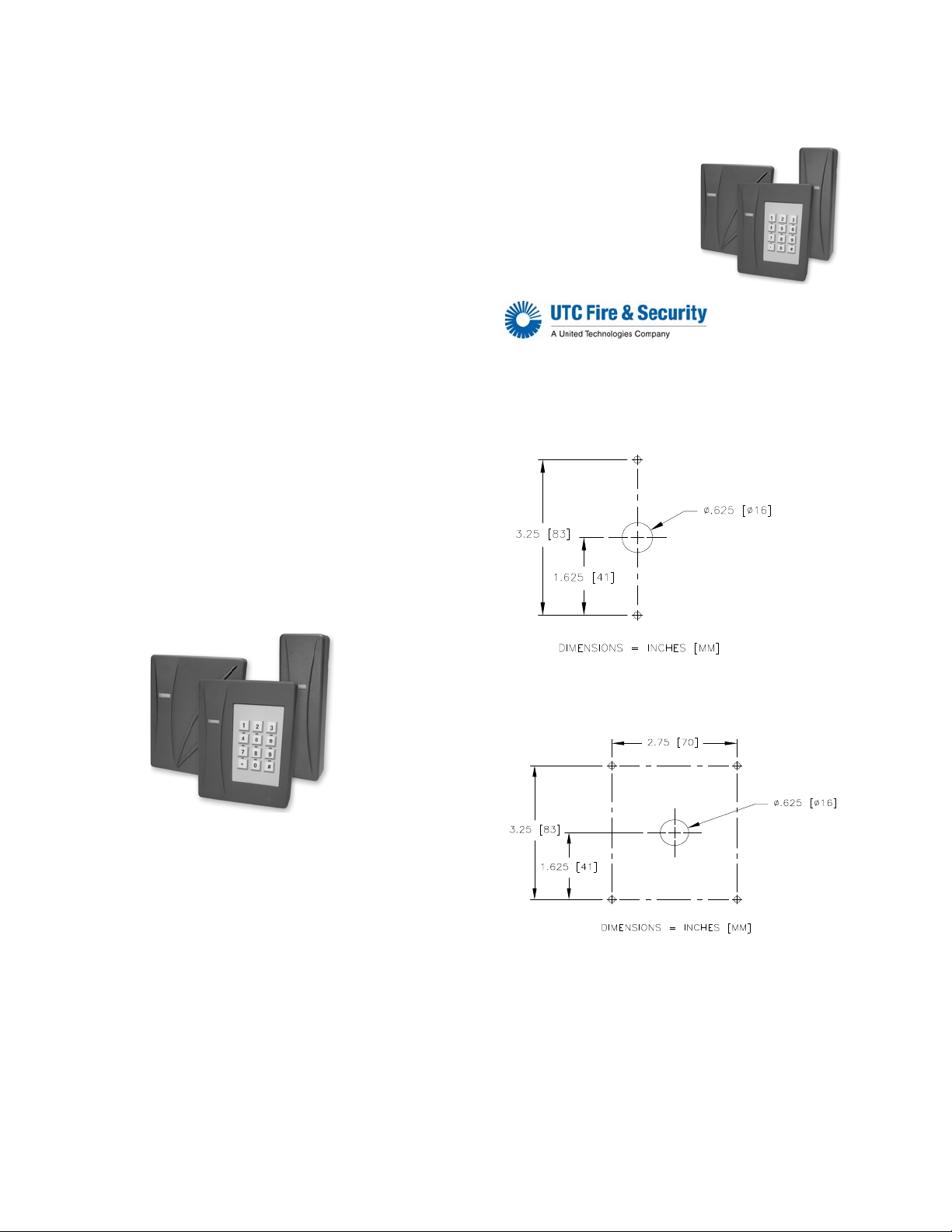
Mounting the Reader
All models of the multi-technology series readers can be
mounted using a U.S. single-gang electrical box or
directly to a wall.
1. Find a suitable mounting position on the door frame
or wall.
Note: For out of doors or wet locations, it is recommended that the gasket provided be installed on the
base as shown in Figure 5.
2. If mounting directly to the wall, use one of the
following methods:
2a. Drill two vertical mounting holes from 3.25”
(83
cm) to 4.891” (125 cm) apart on the mounting
surface of the door frame or wall.
Figure 2. Direct wall mounting
2b. Models 520/525 can be mounted using a second
pair of vertical mounting holes, horizontally
spaced 2.75” (70 cm) from the first pair.
Figure 3. T520/525 Direct wall mounting alternative
3. Drill one 0.625” (15.87 mm) diameter hole in wall for
the pigtail wire connection.
4. Follow the Cable Connection Chart to connect the
reader to the field panel and external door
equipment.
5. Mount the base plate to the wall using the supplied
screws.
6. Install gasket if required, see Figure 5.
7. Install the top cover to the reader base. The base
plate and top cover guides should be aligned, so the
connectors seat correctly.
Page 2
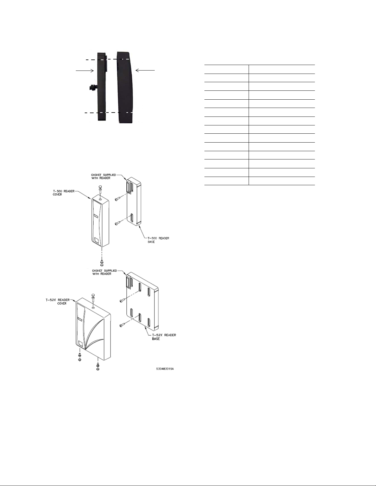
Figure 4. Aligning base plate and top cover
Base plate
Top cover
8. Verify the connection is secure and install the
security screws on the top and bottom of the
reader.
9. Cover the exposed screws with the rubber
lugs provided.
p
Figure 5. Gasket detail
Chart (below) to correctly match the color of
each wire.
Color Signal
Red 6 to 16 VDC
Black Ground
Green Data 0
White Data 1
Orange Green LED Control
Brown Red LED Control
Yellow Beeper Control
Gray Door DI
Pink REX DI
Ta n Tamper Output
Blue Hold
Purple Reserved
........ Drain Wire
2. Use a DC Power source between 6-16 VDC.
3. Verify the reader is properly grounded by
aching the ground wire to an earth ground
att
connection at the power supply or field panel
end of the cable. Connect reader’s drain wire
to the cable shield. Connect shield wires at the
field panel. The recommended cable gauge is
18-gauge to 22-gauge. Check with the cable
supplier to determine the best choice for the
application and installation distance.
Connecting the Cable
1. The readers are supplied with a 12-conductor
cable pigtail with drain wire. Connect the pigtail
to the host panel. Use the Cable Connection
Testing the Reader
1. Power up the reader. Verify the power-on self
test
LED/beep sequence:
- green LED flashes; two short beeps
yellow LED flashes; three short beeps
-
- red LED flashes.
- yellow LED flashes.
2. Verify the yellow LED is on continously
ind
icating the reader is ready.
3. Present a badge that has been properly
enrolled
in the system. Verify the yellow LED
flashes and a short beep is heard.
Removing the Cover
1. Remove all security screws.
2. Pull cover off the base. Refer to Figure 4 on
page 2.
Page 3

Keypad Configuration Card
Cable Distance
Max. @ 12 VDC
AWG
200 ft. (60.96 m) 22
300 ft. (91.44 m) 20
500 ft. (152.4 m) 18
1. Place the reader in tamper mode by briefly
removing and replacing the reader’s cover
while the power is on. The reader stays in
tamper mode for 60 seconds (minimum) after
power is applied or the cover is replaced.
2. Present the keypad configuration card within
ne minute. The LED turns green and a short
o
triple-beep indicates the reader is ready to
configure.
3. Enter the keypad entry within five seconds.
e chart below to identify the correct
Use th
keypad entry.
non-
Mode/Keypad entry Setting UTC
1 * followed by 0
(Factory default
setting)
2 * followed by 1 6 bits per key, no
3 # followed by 3
keys
(0 to 9 only)
4 1 followed by 1
key
(0 to 9 only)
5 1 followed by * 4 bits per key, no
6 1 followed by # 4 bits per key, no
For non-UTC keypad configurations, contact Sales
eering/Pre-Sales Support for assistance.
Engin
8 bits per key, no
fering.
buf
fering.
buf
26 bits output
tom
cus
configuration.
(Contact Sales
Engineering/Pre-
s Support for
Sale
assistance.)
4 bits per key, no
p
arity, up to 9
keys buffered.
arity, up to 10
p
keys buffered.
arity, up to 11
p
keys buffered.
UTC
FCC Compliance
The FCC requires the following statement: This
reader uses radio frequency energy and has been
tested, and complies with the limits of FCC testing.
Changes, modification, or disregard of proper
installation and instructions not expressly approved
by UTC Fire & Security, and is strictly prohibited by
the FCC and could void the user’s authority to
operate the equipment.
Specifications
Colors Black, Charcoal, Light gray
Power supply Linear DC recommended
Power usage T-500: 210 mA @ 12 VDC
Voltage range 6 - 16 VDC
Temperature range
Cable distance to
anel
p
Read Range
(Distances may vary
depend
environment.)
Wiegand output Proximity 4002 (40-bit)
Tamper output Open Collector
Regulatory
appr
standards
ISO Standards Mifare ISO 14443A
UL evaluation for UL Listed Installations:
a. -25°F to 125°F (-32°C to 52°C)
b. Model T-500W
b
ing on
ovals and
Vicinity: up to 4.5" (11.43 cm)
Model T-520W and T-525W
Proximity, HID Proximity, and Vicinity: up to 4.5"
1.43 cm)
(1
The voltage specification for this reader is 6—16
VDC, although 12 VDC or greater is recommended
for better performance and cable run distances.
T-520/T-525: 130 mA @ 12 VDC
a
-31°F to 149°F (-35°C to 65°C)
Proximity Perfect cards are not
supported
reader.
Model T-500W:
- Proximity: up to 3.5" (8.89 cm)
- HID Proximity: up to 3.5" (8.89 cm)
- Mifare: up to 1" (2.54 cm)
Ultralight cards not supported
- Vicinity: up to 5" (12.7 cm)
Model T-520W and T-525W:
- Proximity: up to 5" (15.24 cm)
- HID Proximity: up to 5" (15.24 cm)
- Mifare
Ultralight cards not supported
- Vicinity: up to 5" (12.7 cm)
Mifare 4002 (40-bit)
Vicinity 5502 (55-bit)
UL 294, CE, and FCC (part 15)
Vicinity ISO 15693
by the Transition Series
: up to 1" (2.54 cm)
Page 4

Ordering information
Product Part Number
T-500W (Black; Mullion mount; Wiegand
outpu
t) *
T-520W (Black; 1-Gang US mount; Wiegand
outpu
t) *
T-525W (Black; 1-Gang US mount; Keypad;
Wiegand output
T-500W (Charcoal; Mullion mount; Wiegand
t) *
outpu
T-520W (Charcoal;1-Gang US mount;
Wiegand output
T-525W (Charcoal; Gang US mount; Keypad;
Wiegand output
T-500W (Light gray; Mullion mount; Wiegand
t) *
outpu
T-520W (Light gray; 1-Gang US mount;
Wiegand output
T-525W (Light gray; 1-Gang US mount;
ad; Wiegand output) *
Keyp
Single Gang Mount plate (Black; 1-Gang US
mounting plate for
Single Gang Mount plate (Charcoal; 1-Gang
US moun
Single Gang Mount plate (Light gray; 1-Gang
US moun
Dual Gang Mount plate (Black; 2-Gang US
mounting plate for
Dual Gang Mount plate (Charcoal; 2-Gang US
mounting plate for
Dual Gang Mount plate (Light gray; 2-Gang
US moun
* Installation wrench (Required) 385001001
) *
) *
) *
) *
model T-500)
ting plate for model T-500)
ting plate for model T-500)
models T-52x)
models T-52x)
ting plate for models T-52x)
430209006
430210006
430211006
430209005
430210005
430211005
430209004
430210004
430211004
470677002
470677003
470677001
521228001
521227001
521226001
Copyright © 2012, UTC Fire & Security. All rights
reserved.
The Transition series reader name and logo are
demarks of UTC Fire & Security. Other trade names
tra
used in this document may be trademarks or registered
trademarks of the manufacturers or vendors of the
respective products.
Document number: 460618001K - November 2012
 Loading...