

Page 1
SuperBus 2000 Phone Interface/Voice Module
Installation Instructions
Product summary
The SuperBus 2000® Phone Interface/Voice (PIV) Module
provides phone and voice functions for the Concord™ ,
Concord 4™, and Concord Express™ (v4) panels.
The PIV module allows installers and users to control a panel
— either on-site or from a remote location — through any
touch-tone telephone. Using an onboard digital voice chip, the
system announces status messages through each phone and
speaker connected to the module.
The PIV module also provides phone control for Concord
panels with single or multiple partitions. For multiple partitions,
a module can be used for each partition and connected to a
separate phone line.
The module communicates with the panel through a series of
bus connections and may be powered by the panel or an
auxiliary 12V DC power supply with backup battery.
SuperBus 2000 vs. SuperBus
SuperBus 2000 panels auto-address module unit numbers.
When the panel is powered, a unique device ID number (preprogrammed at the factory) is automatically learned by the
panel. Potential identical unit number conflicts and the need to
manually set DIP switches are eliminated.
Older SuperBus panels can communicate with the PIV module
by manually setting the module’s DIP switches.
SuperBus 2000 Panels
Concord (v2.0-later)
•
• Concord 4
• Concord Express (v4)
SuperBus Panels
Concord (v1.0-1.6)
•
Features
The PIV module includes the following features:
• User-adjustable, speaker volume control.
• On/Off hook detection.
• Extensive 220-plus word vocabulary.
• In-panel cabinet or optional wall mounting.
• Compatibility with Concord panels (v1.0-1.6).
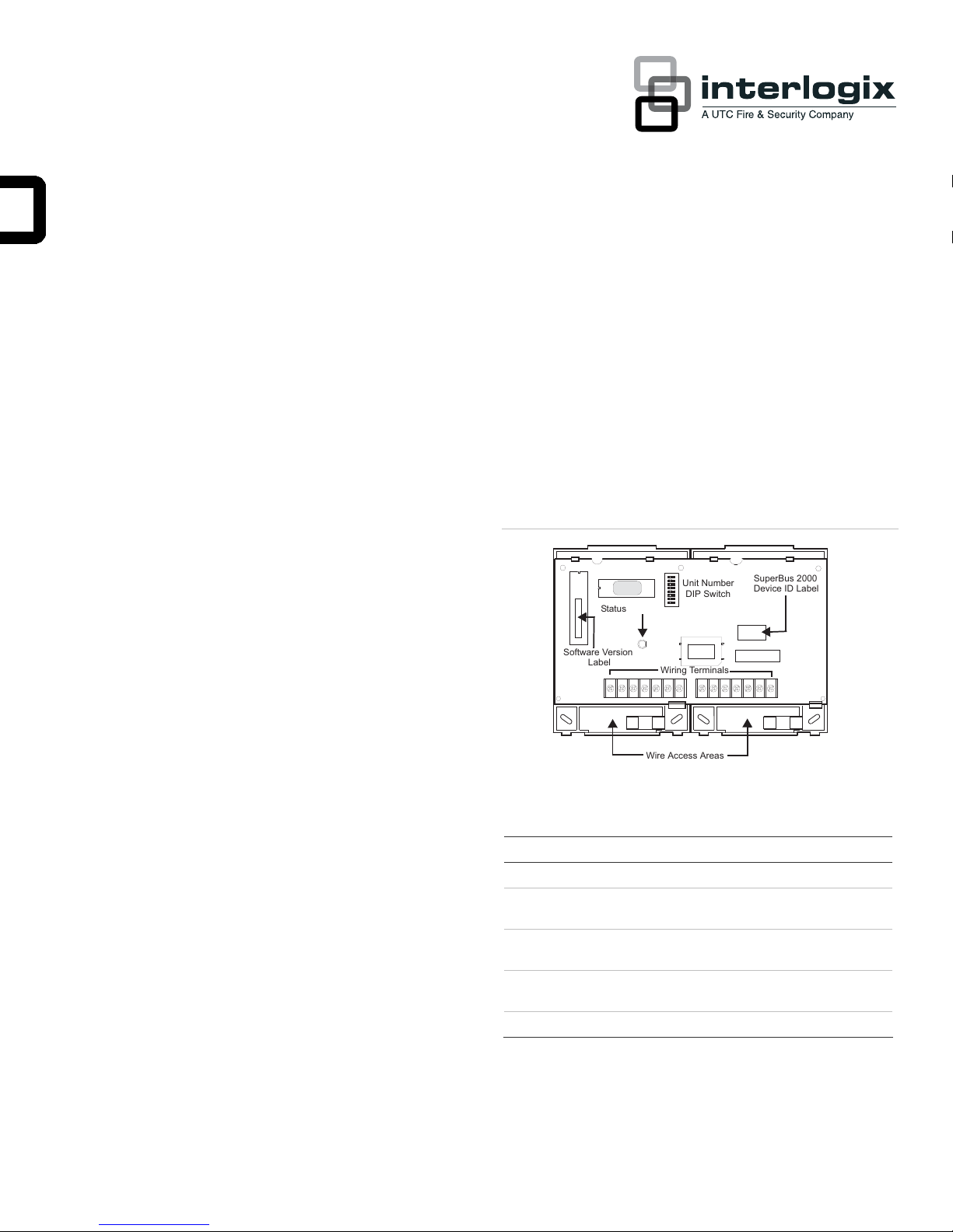
Figure 1: PIV module components
Unit Number
Status LED
Label
Software Version
Table 1: Module component descriptions
Component Function
Status LED Indicates normal panel bus communications.
Unit number DIP
switches
Wiring terminals Provides panel, speaker, and phone
SuperBus 2000 device
ID number label
Software version label Identifies installed module software versions.
DIP Switch
Wiring Terminals
Wire Access Areas
Used to manually set SuperBus unit
numbers.
connections.
Identifies SuperBus 2000 device ID numbers.
SuperBus 2000
Device ID Label
Installation guidelines
P/N 466-1516-01 • REV C • 07APR11 1
When installing the PIV module, use the following guidelines:
Page 2
• Concord systems can accommodate one PIV module per
partition. For multiple partition installations, each module
must be connected to a separate phone line and speaker.
• Give your customer the ability to unplug their system by
connecting the phone line with an RJ-31X jack. This
ensures your customer can unplug the system in cases of
malfunction where they must also use the phone.
• Mount the module inside the panel cabinet or use the
optional plastic wall-mount housing (part no. 60-800).
• Use four-conductor, 22-gauge or larger diameter stranded
wire to connect the module to the panel.
• Install the module inside the panel cabinet or as close to
the cabinet as possible.
• Set each bus module with different bus unit numbers
(must be manually set for Concord panels v1.0-1.6).
• Remember that the module draws a maximum 600 mA
from the panel’s power supply.
• When using panel power to supply bus or hardwired
devices, do not exceed the panel’s total power output.
Refer to specific panel Installation Instructions for further
detail.
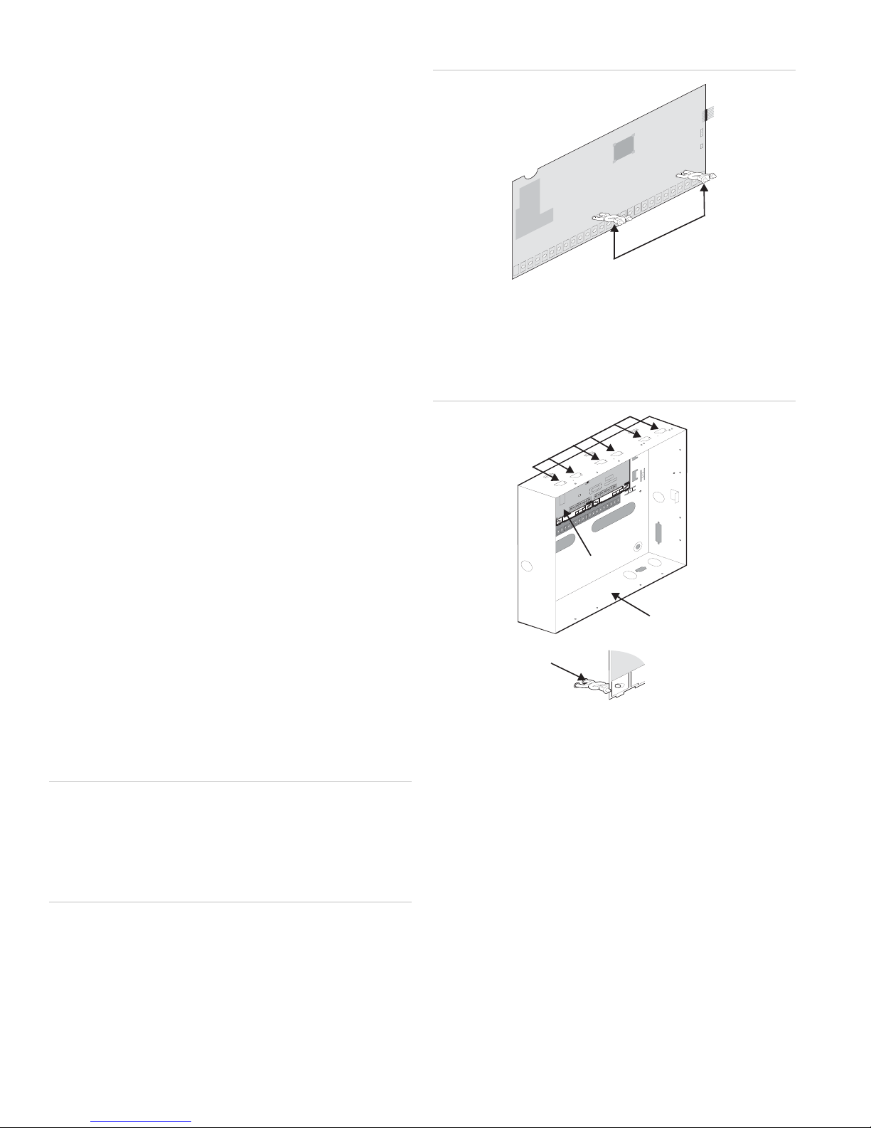
Figure 2: Installing support standoffs
Support
Standoffs
3. On the panel cabinet, slide the top of the backplate on to
the module’s center and top-left mounting clips (see
Figure 3 below).
Figure 3: Mounting the module inside a panel cabinet
Module Mounting
Clips (6)
Tools and supplies
• Slotted screwdrivers
• 3/8”-drive drill and drill bits
• Wire cutter/stripper
• Screws and anchors (included)
• Optional plastic housing (60-800, not included)
• Four-conductor, 22-gauge or larger stranded wire
• RJ-31X Phone Jack (not included)
• DB-8 Cord (included with Concord cabinet)
• Support standoffs (included with Concord cabinet)
Installation
When installing the PIV module, mount the module inside a
panel cabinet or on a wall.
Caution: To prevent damage to the panel or module, remove
the panel’s AC power transformer and disconnect the backup
battery before installation.
You must be free of static electricity when handling electronic
equipment. Touch a grounded metal surface before touching a
circuit board.
Card on Module
Back Plates
Panel Cabinet
(Cover not shown)
Support
Standoff
4. Raise the backplate assembly until it rests on the cabinet’s
left wall tab and the standoffs align with the backplate’s
lower holes (see detail in Figure 3 above).
ing the Module with Optional Plastic Housing:
Mount
1. Loosen cover screws and remove cover (see Figure 4 on
page 3).
Mounting the Module in a Concord Panel Cabinet:
1. Remove panel AC power and disconnect the backup
battery.
2. Install support standoffs (see Figure 2 below).
2 SuperBus 2000 Phone Interface/Voice Module Installation Instructions
Page 3
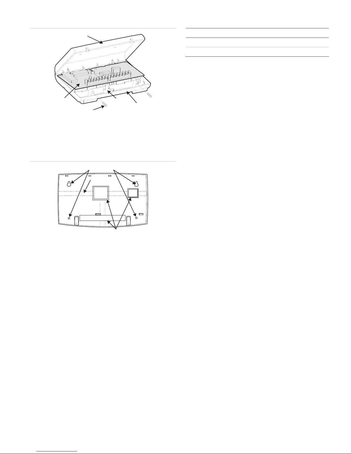
4: Removing cover screws and cover
Figure
Cover
Circuit
Card
Cover Screws (2)
Card
Latch (2)
Backplate
Table 2: Maximum wire lengths (module to panel)
Wire gauge Maximum wire length
18 120 feet
22 40 feet
2. Run a two-conductor, 22-gauge or larger diameter
stranded wire from the module to the speaker.
3. Run a four-conductor, 22-gauge or larger diameter
stranded wire from an RJ-31X jack location to the
telephone protector block.
Installing an RJ-31X Phone Jack
2. Place the backplate at the desired location. Check for
levelness and mark the mounting holes (see Figure 5
below).
Figure 5: Mounting hole locations
Mounting Holes
Wire Channels (3)
Wire Access (3)
3. Drill for mounting holes and install anchors. Next, secure
the backplate to the wall with screws.
4. Drill holes for wires at a wire access location (see Figure 5
above).
5. Remove the circuit board from the original backplate.
6. Install the circuit board on the housing backplate and
gently press the bottom of the board until it snaps into
place under the card latches (see Figure 4 above).
Wiring
Wiring the PIV module requires you to perform the following:
• Run wires for power, bus, speaker, and phone
connections.
• Install an RJ-31X jack for phone line connections.
• Wire connections for Concord system modules.
1. For power and bus connections, run a four-conductor, 22gauge or larger diameter stranded wire from the module to
the panel (refer to Table 2 for maximum wire lengths).
Review the following guidelines prior to installing an RJ-31X
phone jack:
• Do not mount an RJ-31X jack (CA-38A in Canada) more
than five feet away from the panel.
• Connect the panel to a standard (analog) phone line.
Ensure the analog line provides 48V DC and can increase
from 89V to 130V DC while the line is in use.
Note: Concord panels cannot be used on a digital or PBX
phone line. These line types are designed only for digital
devices that operate on 5V DC and higher. Because
Concord panels use analog modems and not digital
converters, adapters, or interfaces, the panel is unable to
use these line types.
• To establish line seizure in Partition 1, install an RJ-31X
phone jack on the home phone line so that the panel is
ahead of all other phones and devices. This allows the
panel to seize the phone line in case of an alarm, even if
the phone is in use or off the hook.
Note: The PIV module does not seize the line during an
alarm.
• If an analog line is not available, contact a
telecommunications specialist and request an analog line
from a phone switch (PBX mainframe) or a 1FB (standard
business line).
Note: Connecting the panel to a PBX-system analog line
prevents access from a home phone. However, you may
access the panel from an off-site phone.
1. Run a four-conductor cable from the TELCO protector
block to the jack location (see
2. Connect a cable end to the phone jack (see
A in Figure 6 on page 4).
B in Figure 6
on page 4).
At the TELCO protector block, remove the home phone
3.
line and splice it to the four-conductor cable’s black and
white wires (see
C in Figure 6 on page 4).
SuperBus 2000 Phone Interface/Voice Module Installation Instructions 3
Page 4

4. Connect the four-conductor’s green and red wires to the
protector block’s TIP (+) and RING (-) posts (see
D in
Figure 6 below).
Wiring - phone line
Note: All partitions must be wired to separate phone lines.
Figure 6: Connecting an RJ-31X jack to a home phone line
BRN
GRN
K
BLAC
Tel co Pr ot ec tor
GREEN
BLACK
GREEN
GREEN
TIP
RJ-31X
JACK
B
Block
(+)
D
C
RING
(-
)
GRY
RED
RED
WHITE (OR YELLOW)
RE
)WOLLEY
ETIHW
DER
RO(
D
A
RJ-31X
Phone Line
Wire Run
Home
Phone
Lines
Partition 1
Figure 8: Wiring the PIV module to a phone line (partition 1)
Phone Interface/Voice
Module Terminal Strip 1
Phone Interface/Voice
Module Terminal Strip 2
DB-8 Cord
Plug
All other partitions
Figure 9: Wiring the PIV module to a phone line (all other
partitions)
Wiring Connections for Concord Panels
Wiring a Concord system requires you to wire for power, bus,
speaker, and phone lines. Refer to the figures shown below for
wiring designated partitions.
Caution: To prevent damage to the panel, or module, remove
the panel’s AC power transformer and disconnect the backup
battery prior to wiring.
Wiring - Power and Bus
All partitions
Figure 7: Wiring the PIV module to panel power and Bus terminals
Phone Interface/Voice
Module Terminal Strip 1
Phone Interface/Voice
Module Terminal Strip 2
Phone Interface/Voice
Module Terminal Strip 2
DB-8 Cord
Plug
Wiring - speakers
Note: Do not connect speakers to the panel if terminals 7 and
8 are connected to PIV terminals 8 and 9 ( see Figure 10 on
e 5).
pag
Panel Terminals
4 SuperBus 2000 Phone Interface/Voice Module Installation Instructions
Page 5

Partition 1
Concord Panels (v1.0–1.6)
Figure 10: Wiring a speaker to a PIV module (partition 1)
Phone Interface/Voice
Module Terminal Strip 1
Not Used
Hardwire Interior
Speaker (60-528)
Phone Interface/Voice
Module Terminal Strip 2
Panel
Terminals
Speaker
All other partitions
Figure 11: Wiring a speaker to the PIV module (all other partitions)
Phone Interface/Voice
Module Terminal Strip 1
Phone Interface/Voice
Module Terminal Strip 2
A module can be set to any unit number (0-15) using the
module DIP switches. If no other bus modules are installed in a
system, the default setting (0) can be used.
If using one module per partition, the lower unit number is
assigned to Partition 1; the higher unit number is assigned to
Partition 2.
Note: Because unit numbers for Concord RF receivers are
factory set to 15, do not use this unit number setting.
Setting DIP Switches
On the module, locate the DIP switches (see Figure 1 on page
1). Next, set the desired unit number from 0 to 15 (see
Figure 12 below) before you turn the power on.
Note: DIP s
Figure 12: Unit number DIP switch settings
witches 1–4 are not used and must be set to OFF.
ADDRESS 0
ON
1234
ADDRESS 3
ON
1234
567
567
8
8
ADDRESS 1
ON
1
234567
ADDRESS 4
ON
1
34
2
56
7
8
8
ADDRESS 2
ON
1
3
2
ADDRESS 5
ON
1
234567
4
567
8
8
Hardwire Interior
Speaker (60-528)
Not Used
Setting the Module Unit Number
In order to ensure proper communication, each panelconnected bus module must have a different unit number.
Concord (v2.0-later), Concord 4, and Concord
Express (v4) Panels
For Concord (v2.0-later), Concord 4, and Concord Express
(v4) panels, unit numbers are automatically learned by the
panel after the system receives power. If using one module per
partition, the panel automatically assigns each module a
partition number.
ADDRESS 6
ON
1234
ADDRESS 9
ON
1234
ADDRESS 12
ON
1234
567
567
567
8
8
8
ADDRESS 7
ON
1234
ADDRESS 10
ON
1
34
2
ADDRESS 13
ON
1
34
2
56
56
56
7
7
7
8
8
8
ADDRESS 8
ON
1
34
2
ADDRESS 11
ON
1
234567
ADDRESS 14
ON
1
234567
56
8
7
8
8
ADDRESS 15--Do not use in Concord RF systems.
ON
1234
567
8
Power Up and Bus Communication
When powering the system or verifying bus communications,
follow the procedures listed below:
Note: To enter program mode and verify unit numbers, you
must connect an alphanumeric touchpad to the Concord panel.
1. Verify all wiring at the panel and module is correct.
2. Connect the panel’s backup battery and plug in the AC
power transformer.
SuperBus 2000 Phone Interface/Voice Module Installation Instructions 5
3. Verify the module’s status LED is on.
Page 6

• If desired, enter program mode to verify if a unit number
exists and that the module is in the correct partition (see
specific panel Installation Instructions for further detail).
Changing Module Unit Numbers — Concord (v1.0–
1.6)
Note: When a module unit number changes, you must
disconnect and reconnect the panel’s AC power transformer
and backup battery.
To avoid conflicts between a bus device and the panel,
consider the following guidelines:
• When possible, assign alphanumeric touchpad unit
numbers prior to all other panel programming.
• Set all unit numbers before powering the system and
entering Program Mode.
1. Remove the panel’s AC power transformer and disconnect
the backup battery.
Troubleshooting
Table 3: PIV troubleshooting
Problem Action/Solution
The status LED is off. 1. Check for proper wiring connections.
2. Ensure the panel’s AC power transformer
is plugged in and the backup battery is
connected.
3. Verify the panel recognizes the module
(see panel Installation Instructions).
4. If the LED remains off, replace the module.
The status LED
remains lit but does
not flash.
The module has a
random, inconsistent
behavior.
1. Verify the panel recognizes the module
(see panel Installation Instructions).
2. Check for proper wiring connections.
3. If the LED fails to flash, replace the
module.
1. Check for proper wiring connections.
2. Verify the panel recognizes the module
(see panel Installation Instructions).
2. Change the module DIP switch setting (see Figure 12).
Remember settings must be different from other bus
devices.
3. Connect the panel’s backup battery and plug in the AC
power transformer. The panel automatically scans all bus
devices and learns any new settings.
Note: If the panel has learned a unit number that is not
assigned a bus device, the system may indicate a bus
failure. To clear a bus failure, enter Program Mode, locate
the unused unit number and press D to delete. Refer to
specific panel Installation Instructions for further detail on
deleting bus devices.
4. Exit Program Mode. The touchpad and bus devices
operate properly and all bus failures are cleared.
Programming and Testing
For complete programming, operating, and testing information,
refer to specific panel Installation Instructions and Owner’s
Manual.
Table 4: Phone troubleshooting
Problem Action/Solution
After wiring an RJ-31X
jack or connecting a
DB-8 cord, the on-site
phone has no dial
tone.
A constant dial tone
prevents dial-out on
home phones.
Table 5: Speaker troubleshooting
Problem Action/Solution
The speakers do not
produce sound.
The speakers
announce the wrong
partition.
The speakers
announce status
messages but do not
sound alarms.
1. Wait two minutes and try again. The panel
may be busy reporting to a central station.
2. Disconnect the panel DB-8 cord from the
RJ-31X jack. If the phone fails to work, the
problem is in the phone wiring.
3. Check RJ-31X jack and TELCO block
wiring. If necessary, replace the RJ-31X jack.
4. Check DB-8 cord connections at the panel
and RJ-31X jack. If necessary, replace the
cord.
1. One or more polarity-sensitive phones
exists on-site. On the RJ-31X jack, reverse
the phone wires connected to the brown and
gray wire terminals.
1. Ensure speakers are properly wired.
2. Ensure the PIV module works correctly.
3. Verify the module is located in the correct
partition (see panel Installation Instructions).
4. If the condition remains, replace speakers.
1. Verify the module is located in the correct
partition (see panel Installation Instructions).
1. Alarm is in Partition 2 and speaker is
connected to panel terminals 7 and 8.
2. Ensure the speaker is wired properly.
3. Ensure the PIV module works correctly.
4. Because terminals 7 or 8 may be shorted
to GND, the speaker output may have shut
down. Disconnect and reconnect panel AC
power and backup battery.
6 SuperBus 2000 Phone Interface/Voice Module Installation Instructions
Page 7

Specifications
Compatibility Concord (v2.0-later), Concord 4, and
Concord Express (v4) panels
Power requirement 12V DC nominal (10V minimum); 600 mA
maximum draw from panel.
Operating temperature 32° to 140°F (0° to 60°C)
Storage temperature -30° to 140°F (-34° to 60°C)
Max. relative humidity 90%, non-condensing
Dimensions 5.5” x 8.0” x 1.5” (H x W x D)
Regulatory information
Manufacturer UTC Fire & Security Americas Corporation, Inc.
1275 Red Fox Rd., Arden Hills, MN 55112-6943,
USA
UL listings UL 985 Household Fire Warning System Units
UL 1023 Household Burglar Alarm System Units
Notices
FCC Part 15 Class B
This equipment has been tested and found to comply with the
limits for a Class B digital device, pursuant to part 15 of the
FCC Rules. These limits are designed to provide reasonable
protection against interference in a residential installation.
This equipment generates, uses, and can radiate radio
frequency energy and, if not installed and used in accordance
with the instructions, may cause harmful interference to radio
communications. However, there is no guarantee that
interference will not occur in a particular installation.
If this equipment does cause harmful interference to radio or
television reception, which can be determined by turning the
equipment off and on, the user is encouraged to try to correct
the interference by one or more of the following measures:
The REN is used to determine the maximum number of
devices that may be connected to your telephone line. In most
areas, the sum of all device RENs should not exceed five (5.0).
REN for this device: 0.4
If this equipment causes harm to the telephone network, the
telephone company may temporarily disconnect your service. If
possible, you will be notified in advance. When advance notice
is not practical, you will be notified as soon as possible. You
will also be advised of your right to file a complaint with the
FCC.
Your telephone company may make changes in its facilities,
equipment, operations, or procedures that could affect the
proper operation of your equipment. You will be given advance
notice in order to maintain uninterrupted service.
If you experience trouble with this equipment, please contact
the company that installed the equipment for service and repair
information. The telephone company may ask you to
disconnect this equipment from the network until the problem
has been corrected or you are sure that the equipment is not
malfunctioning.
This equipment may not be used on coin service provided by
the telephone company. Connection to party lines is subject to
state tariffs.
Contact information
www.utcfireandsecurity.com or www.interlogix.com
For customer support, see www.interlogix.com/customer-
support
Copyright © 2011 UTC Fire & Security. All rights reserved.
• Reorient or relocate the receiving antenna.
• Increase the separation between the equipment and
receiver.
• Connect the affected equipment and the panel receiver to
separate outlets, on different branch circuits.
• Consult the dealer or an experienced radio/TV technician
for help.
FCC Part 68
This equipment complies with part 68 of the FCC Rules. Located on
this equipment is a label that contains, among other information, the
FCC registration number and the ringer equivalence number (REN) for
this equipment. If requested, this information must be provided to the
telephone company.
SuperBus 2000 Phone Interface/Voice Module Installation Instructions 7
 Loading...