

Page 1

SuperBus 2000 2X16 LCD Alphanumeric
Touchpad Installation Instructions
Product summary
The SuperBus® 2000 2x16 LCD (liquid crystal display)
Alphanumeric Touchpad lets you control all programming and
operation of a compatible security system (see “Specifications”
on page 4). The 2-line, 16-character display provides
messag
The touchpad includes police, fire, and auxiliary panic buttons
that can be activated anytime.
A built in speaker provides alarm sounds, status sounds, and
button-press beeps.
es to indicate the current system status.
Installation guidelines
• Mount the touchpad in an environmentally controlled area
32 to 120°F (0 to 49°C).
• When mounting the touchpad, allow at least 4¼ inches on
the left side for the Quick Guide slide-out card.
• For Concord
be connected to the panel. For Concord systems (all
software versions) up to 16 bus devices can be connected
to the panel.
• For Concord systems with software versions 1.0–1.6, each
bus device must have a different unit number setting to
operate correctly. The touchpad unit number is factory set
to 001. For Concord panels with software version 2.0 or
later and Concord Express panels, bus unit numbers are
assigned automatically.
• Table 1 below describes the power used by the touchpad.
™
Express systems, up to 4 bus devices can
Table 2: Maximum touchpad wire lengths
Wire Gauge (Unshielded
or Shielded)
18 750 feet
22 300 feet
Maximum wire length between
touchpad and panel
Tools and equipment needed
• 4-conductor, 22- or 18-gauge wire
• Screwdriver
• Drill/bits
• #6 screws and anchors (included)
• Panhead screws for a gang box installation
• Saw or utility knife for cutting wallboard
Installing the mounting plate
The touchpad can be installed on a wall or electrical gang box,
either single- or dual-gang.
1. Separate the mounting plate from the touchpad by
pressing the tab at the bottom and sliding the mounting
plate down (see Figure 1 below).
Figure 1: Separating touchpad from mounting plate
Lift and Pull
Mounting Plate
Tab
Tab
Table 1: Touchpad power usage
Current (mA) Condition
90 Maximum alarm current
57 Typical operation
12 Standby current (no AC power)
• Do not exceed the maximum available power when using
panel power for bus devices and hardwire detectors (see
the specific panel Installation Instructions for maximum
available power).
• Table 2 below describes the maximum wire lengths
allo
wed between the touchpad and panel.
P/N 466-17
12 • REV D • January 2011 1
2. Place the mounting plate on the wall and mark the four
mounting holes (see Figure 2 on page 2). Be sure to leave
a 4¼-inc
Guide slide-out card.
3. Insert anchors at the marked locations where studs are
not present.
h clearance on the left side to allow for the Quick
Page 2
T
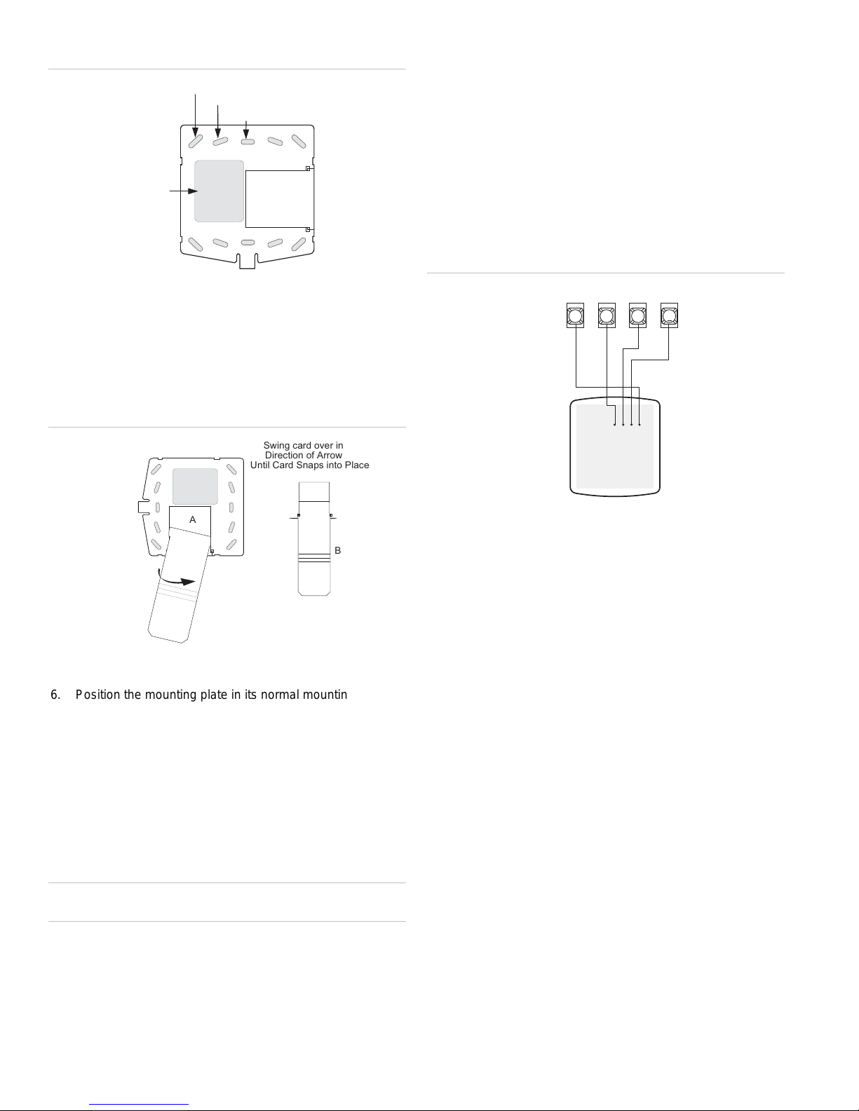
2: Mounting holes
Figure
Wire Access Area
Wall Mounting Holes (4)
Dual-Gang Mounting Holes (4)
Single-Gang Mounting Holes (4)
Wiring
Wiring consists of connecting the touchpad to the panel
terminals.
1. Disconnect the panel transformer and backup battery.
2. Run a 4-conductor, 18- to 22-gauge wire from the panel to
the touchpad location.
3. Splice the 4-conductor cable wires to the red, black,
green, and white wires located on the back of the
touchpad.
4. Connect the touchpad wiring to the panel terminals as
shown in Figure 4 below.
4. Looking at the back side of the mounting plate, turn it so
the tab is on the left and position the Quick Guide slideout card into the slots on back of the mounting plate (see
A in Figure 3 below). Make sure the card is unfolded and
the “Z
ones” section is facing you.
5. Slide the card in the direction of the arrow in Figure 3
below (A) until it snaps into the position shown in (B).
Figure 3: Inserting the Quick Guide Slide-Out card
Swing card over in
Direction of Arrow
Until Card Snaps into Place
A
B
6. Position the mounting plate in its normal mounting position
(tab at the bottom) and fold the card toward you at all
three scored lines. The “Zones” section should be facing
you and the folds should create a tab to slide the card in
and out.
7. Align the mounting plate wall-mount holes with the wall
anchors and secure the back-plate to the wall using the
screws provided.
OR If installing the back-plate on an electrical gang box,
line up the appropriate gang box holes on the mounting
plate with the gang box holes and secure the back-plate to
the gang box using the screws provided.
Caution: Do not over tighten screws or the back plate may
bend and prevent the touchpad from mounting properly.
8. For wall-mounted installations, cut a hole in the wall in the
wire access area of the mounting plate to pull your cable
through for wiring.
Figure 4: Wiring touchpad to panel terminals
+12V
A
BUS
B
6
NEERG/A SUB
GND/BLACK
BUS B/WHITE
BACK OF
OUCHPAD
GND
3 4 5
+12V/RED
Attaching the Touchpad to the Mounting Plate
Align the four slots on the touchpad with the four tabs on the
mounting plate and slide the keypad down until you hear the
latch on the mounting plate click into place.
Power Up
After making all wiring connections from the touchpad to the
panel, you are ready to power up the panel. Upon power up,
the panel scans the bus for connected devices and
automatically learns the unit number of each bus device.
Note: If you plan on installing systems with no alphanumeric
touchpads, it is recommended that you keep an alphanumeric
touchpad with you, specifically for programming. This touchpad
can be quickly connected and disconnected from the header
pins on the lower portion of the panel circuit board, as
described later in this document.
To power up the panel and verify bus communication:
1. Verify that all wiring between the panel and touchpad is
correct.
Note: If the touchpad does not display the date and time,
see “Troubleshooting” on page 4.
Connect the panel battery and plug in the panel
2.
transformer. Alphanumeric touchpads should show a date
and time display.
Connecting the touchpad for system programming only
or installations that don’t include an alphanumeric touchpad
F
as a permanent part of the system, you can connect one for
2
SuperBus 2000 2X16 LCD Alphanumeric Touchpad Installation Instructions
Page 3

system programming to the Programming Touchpad Header
on the panel.
To do this you must first connect a Programming Touchpad
Cable (60-791) to the touchpad wires (see Programming
Touchpad Cable Installation Instructions—466-1604, included
with the cable). Then, use the appropriate procedure for
connecting the touchpad.
To connect a programming touchpad to a Concord
press or Concord panel with software version 2.0 or
Ex
later:
1. With the panel powered up, connect the cable to the
Programming Touchpad Header (see Figure 5 below).
Figure 5: Connecting a programming touchpad
Programming
Touchpad
Cable (60-791)
2. Activate the service touchpad by pressing 8 + CODE + 0 +
2.
3. Enter program mode by pressing 8 + installer/dealer
CODE + 0 + 0 and program the panel using the panel
documentation.
4. When programming is completed, simply disconnect the
programming touchpad.
To connect a programming touchpad to a Concord panel
ith software versions 1.0–1.6:
w
1. Disconnect AC and backup battery power.
2. Connect the cable plug to the panel Programming
Touchpad Header pins (see Figure 5 above).
3.
Reconnect the AC and backup battery power. The
touchpad briefly displays ***********,
SCANNING BUS DEVICES, then shows a time and date
display.
Note: If the touchpad does not respond as described in step 3,
there may be a bus conflict. To correct this, change the
touchpad unit number as described in the section “Changing
the Touchpad Unit Number.”
Removing the programming touchpad from Concord
p
anels with software versions 1.0–1.6:
To prevent a trouble condition, you must delete the
programming touchpad unit number from Concord panel
memory before disconnecting it.
1. After programming is completed, return to the
ACCESSORY MODULES menu, then press É. The
display should read BUS DEVICES.
2. Press É. The display shows the lowest unit number and its
device name.
3. Press A or B until the display shows the programming
touchpad unit number.
4. Press D to delete the device and its unit number from
panel memory. The display shows:
UNIT - TYPE
14-NONE
5. Exit program mode and disconnect the programming cable
from the panel header.
Testing
Caution: Contact the Central Monitoring Station before
activating any alarms, to avoid dispatching local police and fire
departments.
Test the touchpad by arming/disarming the system, activating
the touchpad panics, bypassing sensors, and by turning chime
and lights on/off to verify correct operation. Refer to the panel
documentation for system operating instructions.
Adjusting Display
The touchpad display can be adjusted for easier viewing to
help compensate for lighting conditions in the touchpad
location. The brightness adjustment lightens or darkens the
background. The contrast adjustment lightens or darkens the
text.
To adjust display brightness:
Enter user programming mode by pressing 9 + user,
1.
partition, or system master CODE. The display shows
SYSTEM MENU, then TIME AND DATE
(Concord panels with software versions 1.0–1.6 display
USER CODES.)
2. Press B until the display shows OPTIONS, then press É.
The display shows DOWNLOADING ON/OFF (current
setting).
3. Press B until the display shows TOUCHPAD
BRIGHTNESS 2 (default setting).
4. Enter a setting from 0 (darkest background) to 3 (brightest
background), then press É.
5. The display flashes the entered selection, then stops after
pressing É and displays the new setting and brightness
level.
6. Exit user programming mode by entering:
Ç + 0 + 0 + É for Concord panels with software
versions 2.0 or later
or
Ç + 7 + É for Concord panels with software versions 1.0–
1.6.
To adjust display contrast:
Enter configuration mode by pressing the D and 6 buttons
1.
together for at least two seconds. The display shows DA
nnn.
SuperBus 2000
2X16 LCD Alphanumeric Touchpad Installation Instructions 3
Page 4

2. Press and release the 1 and 2 buttons together
repeatedly, until the desired contrast level is displayed.
3. Press Ç and the display briefly shows DONE, then shows
the time and date.
Troubleshooting
Table 3 below describes what to do if the touchpad does not
operate correctly.
Table 3: Troubleshooting
Problem Action/Solution
Touchpad doesn’t
power up (no display
and no beeps when
buttons are pressed).
Touchpad display
appears blank, but
beeps sound when
buttons are pressed.
Touchpad display
shows a flashing *,
indicating a trouble
condition and system
doesn’t respond to
commands from
touchpad.
Check for correct wiring connections at
touchpad and panel terminals.
Make sure panel battery is connected
correctly and that the panel transformer is
plugged in.
Make sure panel transformer is not plugged
into an electrical outlet controlled by a
switch. Relocate transformer to an
unswitched outlet location, if necessary.
Check the touchpad display contrast setting.
It may be set to 0 (no display).
Check for correct bus wiring connections
(green and white wires) at touchpad and
panel terminals.
Make sure touchpad unit number is set to a
different number than all other bus devices.
If necessary, change the touchpad unit
number (see procedure on this page).
(Concord panels with software versions 1.0-
1.6 only.)
4. Press Ç to exit from the configuration mode.
Note: If the new touchpad unit number was previously
learned by the panel, communication between the
touchpad and the panel begins immediately. However, if
the new touchpad unit number has never been learned by
the panel, continue with step five.
5. Force the panel to scan bus devices as follows:
For systems where this is the only installed touchpad,
remove panel AC and battery power, then re-apply power.
For systems with more than one touchpad, go to another
system touchpad and enter 8 + installer/dealer CODE + 0
+ 1. The display shows SCANNING BUS DEVICES, then
a time and date display.
The touchpad and all other bus devices should operate
correctly and any bus failures should be cleared.
Note: If the panel still indicates a bus failure the panel may
have previously learned a unit number that is no longer used
by any bus device. See the specific panel Installation
Instructions for more information on deleting unused unit
numbers.
Specifications
Compatibility Concord, Concord Express, Concord Ultra
Panels
Power requirements 12 VDC nominal (see Table 1 on page 1 for
more information)
Operating temperature 32 to 120°F (0 to 49°C)
Humidity 70% relative, non-condensing
Dimensions 5.0 x 4.5 x 0.75 in. (L x W x D)
Installation Wall mount
Changing the Touchpad Unit Number (Concord
Panels with Software Version 1.0-1.6 Only)
Use the following guidelines when changing device unit
numbers to avoid communication conflicts between bus
devices and the panel:
• All bus devices with DIP switches (LED Touchpads,
ESMs, HIMs, etc.) must be set to the desired unit number
before applying power and entering program mode.
• Whenever possible, assign touchpad unit numbers before
all other panel programming.
To change the touchpad unit number:
At the touchpad, press and hold the D and 6 buttons
1.
together for at least 2 seconds. The display should show
DA n, where n is the touchpad current unit number (000 -
015).
Note: At this time, the touchpad is in configuration mode
and no longer communicating to the panel. The system
may immediately indicate a bus failure. Ignore the failure
and continue with the procedure. The bus failure will clear
after successfully changing the touchpad unit number.
2. Press É. The display shows ENTER _.
3. Enter the desired three digit unit number (000 - 015), then
press É. The display shows DA n, where n is the new
touchpad unit number.
Note: Do not use unit number 15 in Concord RF systems.
Regulatory information
Manufacturer UTC Fire & Security Americas Corporation, Inc.
1275 Red Fox Rd., Arden Hills, MN 55112-6943,
USA
UL listings UL 985 Household Fire Warning System Units
UL 1023 Household Burglar-Alarm System Units
UL1610 Central Station Burglar-Alarm Units
(Commercial Burglary)
Note: See specific panel Installation Instructions
for complete UL installation requirements for the
system you are installing
Contact information
For contact information, see www.utcfireandsecurity.com or
www.interlogix.com.
For technical support, toll-free: 888.437.3287 in the US
including Alaska, Hawaii, Puerto Rico, and Canada. Outside
the tool-free area, contact your dealer.
Copyright © 2011 Interlogix, a UTC Fire & Security Company.
All rights reserved.
4 SuperBus 2000 2X16 LCD Alphanumeric Touchpad Installation Instructions
 Loading...