

Page 1

Simon XT Talking Touchscreen Installation
Sheet
Description
The Simon XT Talking Touch Screen (models 60-924-RF-TS
and 60-924-RF-TS-N without power supply) features a color
3.5 inch LCD screen with a graphical user interface designed
to control basic functionality of the Simon XT (v1.3 or later) and
Simon XTi control panels. Up to four touch screens can be
learned (programmed) into each Simon XT or XTi panel.
The touch screen provides a convenient option for the
following system operations:
• Arm the system (doors, windows, and motion sensors).
• Disarm the system.
• Activate a panic alarm to call the central monitoring station
in a nonmedical emergency.
• Check system status.
• Turn system controlled lights on or off (depending on your
system configuration).
• Lock and unlock system-controlled door locks (depending
on your system configuration).
• Hear voice feedback of the status of the Simon XT or XTi
control panel.
• Always do a sensor test before attaching the touch screen
to the wall.
• Do not wrap the antenna into the backplate. Follow the
instructions to install the antenna into the wall.
Sensor naming
Please use the following as a guide when naming sensors:
• Sensor names must have the word “window” or “door”
from the text library to interact with the touch screen Doors
and Windows icons on the Main screen.
• The Motion icon is controlled by sensors that are
programmed into the following groups: 15, 17, 18, 20, 28,
32.
• The Property icon is controlled by the following sensors:
• All sensors learned into Group 43.
• Sensors that are not named “window” or “door”.
• Sensors not learned into the Motion groups.
• Sensors that are named keyfob or keychain.
To program (learn) the touch screen into the Simon XT
panel:
1. Press the down arrow button on the panel and scroll to
Installation
Use the following guidelines when adding this touch screen to
the Simon XT or XTi system:
• The touch screen should be the last sensor programmed
(learned) into the panel.
• Program (learn) the touch screen into the panel as a
sensor.
• Program touch screens using sensor groups 00, 01, 04,
05, 06, or 07.
• The touch screen will work best if mounted greater than 3
ft. (approximately 1 m) from the Simon XT panel.
• Avoid mounting the touch screen directly behind the
Simon XT or XTi panel on the opposite side of the wall.
P/N 466-2400 • REV D • 25FEB13 1
System Programming.
2. Press OK.
The panel displays
3. Enter the installer access code and press OK.
4. Scroll to Sensors and press OK.
5. When the panel displays
The panel blinks
next available zone number). You can enter a different
zone number if desired.
6. On the touch screen:
A. Press the Settings button.
B. Press the Down arrow until the Clear and Enroll
button appears.
Enter Code.
Learn Sensor, press OK.
Trip Sensor nn (where nn is the
Page 2
C. Press the Clear and Enroll button. The touch screen
should indicate it is waiting for enrollment.
7. On the panel, you can now program the group number
(00, 01, 04, 05, 06, or 07) and press OK.
8. On the panel, press the Up or Down arrow to select a
name for the touch screen and press OK. (Refer to the
Simon XT installation instructions for programming sensor
text.)
You can select something simple, such as “Touch Pad”, or
use additional descriptors, such as “Bedroom Touch Pad”.
The touch screen will indicate enrollment success or
failure.
Note: During install mode, it is normal for the four blue
LEDs on the panel to blink as this indicates the panel is
updating the touch screen status. Do not leave program
mode if you have modified sensor information or are
downloading a company logo while the four blue arming
LEDs on the panel are blinking (this may disrupt
configuration).
9. To verify that the touch screen is programmed (learned),
press the Status button on the panel repeatedly to leave
system programming and return to normal panel
operation.
10. Press the Settings button on the touch screen and press
the Hear button.
The touch screen should announce the panel arming level
and status, such as Disarmed System Okay.
To program (learn) the touch screen into the Simon XTi
panel:
1. On the Simon XTi panel, press the
right corner of the touchscreen.
2. From the Status & Settings screen, press
the Programming option and press ENTER.
icon in the bottom
to scroll to
3. On the panel, you can now program the group number
(00, 01, 04, 05, 06, or 07) by pressing EDIT next to Sensor
Group.
4. On the panel, select a name for the touch screen by
pressing EDIT next to Sensor Name.
You can select something simple, such as “Touch Pad”, or
use additional descriptors, such as “Bedroom Touch Pad”.
The touch screen will indicate enrollment success or
failure.
Note: Do not leave program mode if you have modified
sensor information or are downloading a company logo,
this may disrupt configuration).
5. To verify that the touch screen is programmed (learned),
press the Close button on the panel repeatedly to leave
system programming and return to normal panel
operation.
6. Press the Settings button on the touch screen and press
the Hear button.
The touch screen should announce the panel arming level
and status, such as Disarmed System Okay.
Refer to your Simon XTi panel documentation for other
programming options.
Note: If you would like this touch screen operation to be code
protected, you can enable this feature by following these steps:
1. Select the Settings menu.
2. Scroll to “Code Required Access” and select Yes.
With code required access, not all icons will be displayed.
Sensor test
The touch screen is sensitive to its orientation to the control
panel. For that reason, we recommend you test the touch
screen before you mount it on the wall.
1. Enter the dealer or installer code and press OK.
2. From the Programming screen, press SENSORS.
3. From the Sensors screen, press LEARN SENSORS. the
panel displays the Edit Sensor screen.
2. On the touch screen:
A. Press the Settings button.
B. Press the Down arrow until the Clear and Enroll
button appears.
C. Press the Clear and Enroll button. The touch screen
should indicate it is waiting for enrollment.
2 Simon XT Talking Touchscreen Installation Sheet
To test the touch screen with the Simon XT (v1.4) panel:
In the Setting menu, press the Test button under RF Test. If
less than three bars appear, see “To relocate the touch
screen:” on page 3.
To test the touch screen with the Simon XT (v1.3) panel:
1. Make sure the panel is disarmed.
2. Press the down arrow button on the panel and scroll to
System Programming.
3. Press OK.
4. When the panel displays
appropriate code and press OK.
Enter Code, enter the
Page 3

5. Scroll until the panel displays Sensor Test, press OK
to start the sensor test.
2. Increase the distance from the original position. Retest
until an acceptable location is found.
The panel will prompt you to trip each sensor one at a
time.
6. To trip the touch screen, press the Emergency button.
You can follow the panel voice prompting to test the
sensors in any order. You should hear the panel beep the
number of packets received. The panel will also display
the number of packets received. If you do not hear 6 to 8
panel beeps, see “To relocate the touch screen:” below.
To test the touch screen with the Simon XTi panel:
1. Make sure the panel is disarmed.
2. Access the System Tests screen through the Status &
Settings screen by pressing ENTER next to
PROGRAMMING.
3. Enter the access code and press OK.
4. Press SYSTEM TESTS.
5. Press SENSOR TEST.
6. All learned in sensors will be displayed on this screen.
Press
to scroll through the pages).
7. To trip the touch screen, press the Emergency button.
You should hear the panel beep the number of packets
received. The panel will also display the number of
packets received. If you do not hear 6 to 8 panel beeps,
see “To relocate the touch screen:” below.
8. Press Close repeatedly to exit.
You should also perform the following to validate the touch
screen installation:
1. Arm the panel and verify that the panel and touch screen
indicate that the panel is armed.
2. Wait 10 minutes and verify that you do not get a “loss of
connection” message and that the RF icon is not red.
We recommend that you test the touch screen after all
programming is completed and whenever a touch screen
related problem occurs.
To verify communication between the panel and the touch
screen, exit programming mode and then press the System
Status icon on the touch screen. The touch screen should
announce the correct system status.
3. Mount the touch screen in the new location (see Figure 1
on page 4).
Note: If you cannot get the touch screen to trip, test a known
good touch screen at the same location. If the replacement
touch screen functions, contact UTC Fire & Security for repair
or replacement of the faulty touch screen.
To mount the touch screen:
1. Remove the touch screen from the mounting base by
inserting a small screwdriver into the slot on the bottom of
the touch screen (see Figure 1 on page 4).
2. Hold the base on the wall at the mounting location and
mark the mounting holes, antenna drop, and power drop.
3. Drill 1/8 inch holes into the wall for plastic anchors at the
mounting hole locations. Cut both the antenna and power
wire drop openings to the size of the opening in the base.
4. Push the two plastic anchors into the drilled holes and
tighten screws within a ¼ inch of the anchors.
5. Feed the power supply plug through the power wire
opening.
6. Hang the base over the screws, level, and tighten the
screws.
7. Load four AAA batteries into the battery compartment on
the back of the touch screen.
8. Plug the power into the back of the touch screen, and
secure the power wire to the loop with the tie wrap
provided.
9. Feed the antenna wire from the back of the touch screen
through the rectangular wire drop opening in the wall.
10. Angle the top of the touch screen into the hooks on the top
of the base. Start feeding the power cable through the wire
drop, and swing the bottom of the touch screen into the
lower part of the base until you hear it click.
11. When choosing the AC outlet for the power supply, make
sure the outlet is not controlled by a switch.
Note: If necessary, use a soft cloth to clear smudges on the
screen; do not use glass cleaner on the screen.
To relocate the touch screen:
1. Test the touch screen a few inches from the original
position.
Simon XT Talking Touchscreen Installation Sheet 3
Page 4
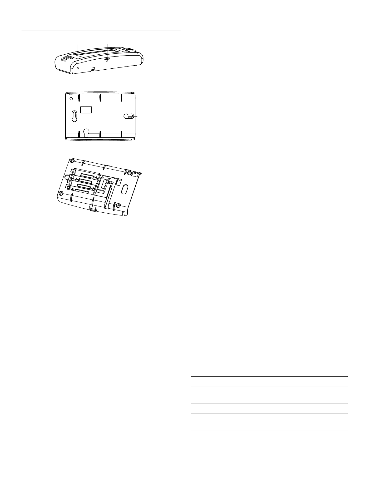
Figure 1: Mounting
Mounting
hole
Opening slotReset button
Antenna wire opening
Mounting
hole
3. Briefly disconnect the AC power (this will clear the battery
fault).
4. Reconnect AC power.
Note: If AC power is lost and batteries are not present or are
depleted, the touch screen will not power up until AC power is
restored (even if new batteries are installed).
Reset button
The Reset button is located on the bottom left side of the touch
screen mounting plate (see Figure 1 above). To power cycle
the touch screen, use a toothpick to depress the recessed
Reset button.
Power wire opening
Power plug-in
Power wire loop
Batteries
Operation
Refer to the Simon XT Touch Screen Quick Operation Guide
for basic touch screen operation information. Refer to the panel
documentation for complete Simon XT and XTi programming
and operation information.
Setting the clock
You can set the touch screen clock by setting the clock on the
Simon XT or XTi panel.
Battery replacement
Note: Do not press the Reset button while in programming
mode.
Clear operation
If the Simon XT or XTi panel is connected to an online service,
some information (such as a dealer logo) can be stored in the
touch screen memory. To erase touch screen memory and
restore to factory default, simply relearn the touch screen into
the panel again. The learn in process begins by clearing the
touch screen memory. To keep memory clear, learn the touch
screen into a Simon XT or XTi panel that has no online service
supported.
Troubleshooting
• If your touch screen fails to enroll, go to the Simon XT
panel, delete that touch screen from the panel, and then
repeat the enroll procedure.
• If the touch screen chime does not announce the zone
name completely, it is likely due to the zone information
not being sent to the touch screen during installation. To
correct the problem, delete the touch screen and relearn
the touch screen again.
When the touch screen batteries are low, the touch screen will
display the red battery icon on the Home and Settings screens.
Note: We recommend that you replace the batteries once a
year and after any significant power outage.
1. Remove the touch screen from the mounting plate by
inserting a small screwdriver into the slot on the bottom of
the touch screen.
2. Replace all batteries being sure to follow the polarity
instructions (see “Specifications ” below for recommended
batteries).
Avoid touching the touch screen face while you are
• Red text on the Door Lock page indicates an open door or
a door that is not monitored.
Specifications
Compatibility Simon XT (version 1.3 and later), Simon XTi
Power Input 100-240 VAC, 250 mA
Output 6 VDC, 500 mA
Batteries Four 1.5 V, Alkaline, AAA
Dimensions (W × H ×
D)
Color White
5.5 × 3.6 × 1.1 in. (140 × 92 × 28 mm)
replacing the batteries.
4 Simon XT Talking Touchscreen Installation Sheet
Page 5

Operating environment
Temperature
Relative humidity
32 to 104°F (0 to 40°C)
0 to 90% noncondensing
Regulatory information
FCC This device complies with part 15 of the FCC rules. Operation
is subject to the following conditions:
1. This device may not cause harmful interference.
2. This device must accept any interference received,
including interference that may cause undesired operation.
Changes or modifications not expressly approved by the
party responsible for compliance could void the user’s
authority to operate the equipment.
FCC ID: B4Z-924-2WTTS
IC: 1175C-9242WTTS
This product has been investigated and approved by ETL for
use as a supplementary keypad for the Simon XT system.
Contact information
www.utcfireandsecurity.com or www.interlogix.com
For customer support, see www.interlogix.com/customer-
support
© 2013 UTC Fire & Security Americas Corporation, Inc.
Interlogix is part of UTC Climate Controls & Security, a unit of
United Technologies Corporation. All rights reserved.
Simon XT Talking Touchscreen Installation Sheet 5
 Loading...