

Page 1

POC2052-4P-1CX PoE
Over Coaxial Extender User
Manual
P/N
1073393-EN • REV A • ISS 27FEB18
Page 2
Copyright
©
Interlogix is part of UTC
Corporation
Trademarks and patents
Trade names used in this document may be trademarks or registered trademarks of the
manufacturers or vendors of the respective products.
Manufacturer
Interlogix
2955 Red Hill Avenue, Costa Mesa, CA 92626
A
UTC Fire & Security B.V.
Kelvinstraat 7, 6003 DH Weert, The Netherlands
Version
This document applies to
FCC compliance
This device complies with part 1
two conditions: (1) This device may not cause harmful interference, and (2) this device
must accept any interference received, including interference that may cause undesired
operation.
nce
Class A:
A digital device, pursuant to part 15 of the FCC Rules. These limits are designed to
provide reasonable protection against harmful interference when the equipment
operated in a commercial environment. This equipment generates, uses, and can radiate
radio frequency energy and, if not installed and used in accordance with the instruction
manual, may cause harmful interference to radio communications. Operation of t
equipment in a residential area is likely to cause harmful interference in which case the
user will be required to correct the interference at his own expense.
Canada
This Class A digital apparatus complies with CAN ICES
Cet appar
(A)/NMB
ACMA compliance
Notice!
radio interference in which case the user may be required to take adequat
Certification
EU directives
This product and
comply therefore with the applicable harmonized European standards listed under the
EMC Directive 2014/30/EU, the RoH
2012/19
as unsorted municipal waste in the European Union. For proper recycling, return this
product to your local supplier upon the purchase of equival
dispose of it at designated collection points. For more information see:
www.recyclethis.info.
Product warnings and
disclaimers
THESE PRODUCTS ARE INTENDED FOR SALE TO AND INSTALLATION BY
QUALIFIED PROFESSIONALS. UTC FIRE & SECURITY
ASSURANCE THAT ANY PERSON OR ENTITY BUYING ITS PRODUCTS,
INCLUDING ANY “AUTHORIZED DEALER” OR “AUTHORIZED RESELLER”, IS
PROPERLY TRAINED OR EXPERIENCED TO CORRECTLY INSTALL FIR
SECURITY RELATED PRODUCTS
For more information on war
check
Contact information and
manuals
For contact information go to:
To get translations for this and other product manuals go to:
www.firesecurityproducts.com
FCC complia
2018 United Technologies Corporation.
Climate, Controls & Security, a unit of United Technologies
. All rights reserved.
-5923, USA
uthorized EU manufacturing representative:
POC2052-4P-1CX.
5 of the FCC Rules. Operation is subject to the following
This equipment has been tested and found to comply with the limits for a Class
is
his
-003 (A)/NMB-3 (A).
eil numérique de la classe A est conforme à la norme CAN ICES-003
-3 (A).
This is a Class A product. In a domestic environment this product may cause
e measures.
- if applicable - the supplied accessories too are marked with "CE" and
/EU (WEEE directive): Products marked with this symbol cannot be disposed of
.
www.firesecurityproducts.com/policy/product-warning/ or scan the QR code:
ranty disclaimers and product safety information, please
www.interlogix.com or www.firesecurityproducts.com.
.
S Directive 2011/65/EU.
ent new equipment, or
CANNOT PROVIDE ANY
E AND
Page 3

Content
Important information 2
Chapter 1 Introduction 3
Package contents 3
Chapter 2 Hardware description 4
Physical dimensions 4
Front panel 4
LED indicators 5
Product specifications 7
Chapter 3 Installation 11
Installation precautions 11
Chapter 4 Application diagram 14
Point to multi-point 14
Multi-point to multi-point 16
Applications of POC252-1CXP-1T or POC switch with coaxial
cable 17
Appendix A Networking connection 21
POC2052-4P-1CX PoE Over Coaxial Extender User Manual 1
Page 4

Important information
Limitation of liability
To the maximum extent permitted by applicable law, in no event will UTCFS be liable
for any lost profits or business opportunities, loss of use, business interruption, loss of
data, or any other indirect, special, incidental, or consequential damages under any
theory of liability, whether based in contract, tort, negligence, product liability, or
otherwise. Because some jurisdictions do not allow the exclusion or limitation of liability
for consequential or incidental damages the preceding limitation may not apply to you.
In any event the total liability of UTCFS shall not exceed the purchase price of the
product. The foregoing limitation will apply to the maximum extent permitted by
applicable law, regardless of whether UTCFS has been advised of the possibility of
such damages and regardless of whether any remedy fails of its essential purpose.
Installation in accordance with this manual, applicable codes, and the instructions of the
authority having jurisdiction is mandatory.
While every precaution has been taken during the preparation of this manual to ensure
the accuracy of its contents, UTCFS assumes no responsibility for errors or omissions.
Advisory messages
Advisory messages alert you to conditions or practices that can cause unwanted
results. The advisory messages used in this document are shown and described below.
WARNING: Warning messages advise you of hazards that could result in injury or loss
of life. They tell you which actions to take or to avoid in order to prevent the injury or
loss of life.
Caution: Caution messages advise you of possible equipment damage. They tell you
which actions to take or to avoid in order to prevent damage.
Note: Note messages advise you of the possible loss of time or effort. They describe
how to avoid the loss. Notes are also used to point out important information that you
should read.
2 POC2052-4P-1CX PoE Over Coaxial Extender User Manual
Page 5

Chapter 1
Introduction
The description of the IFS POC2052-4P-1CX model is as follows:
4-port 10/100TX PoE Extender
Unless specified, the term “POC extender” mentioned in this user manual refers to the
POC2052-4P-1CX.
Package contents
Open the box of the industrial PoE+ switch and carefully unpack it. The box should
contain the following items:
The POC extender × 1
DIN rail kit x 1
Wall mounting kit x 1
If any of these are missing or damaged, contact your dealer immediately. If possible,
retain the carton including the original packing materials for repacking the product in
case there is a need to return it to us for repair.
3 POC2052-4P-1CX PoE Over Coaxial Extender User Manual
Page 6
Chapter 2
Hardware description
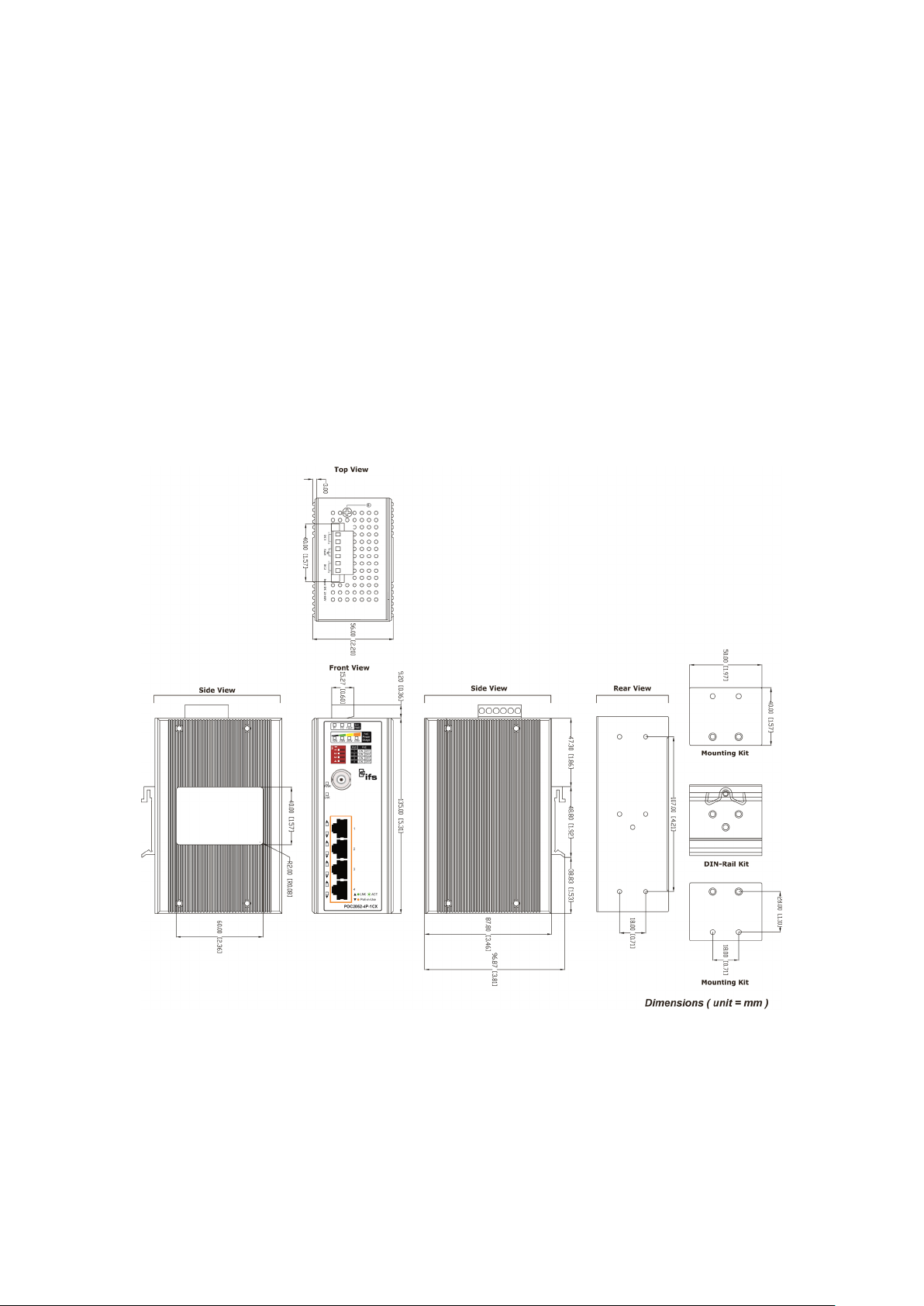
Physical dimensions
Dimensions (W x D x H): 135 x 87.8 x 56 mm
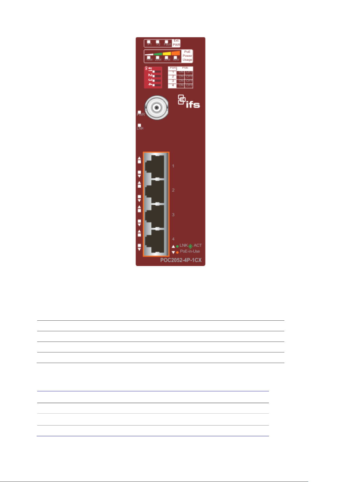
Front panel
The front panel of the POC extender consists of 1BNC female/RJ45 connector and four
10/100BASE-TX RJ45 ports. The LED indicators are also located on the RJ45 ports of
POC extender.
4 POC2052-4P-1CX PoE Over Coaxial Extender User Manual
Page 7
Chapter 2: Hardware description
LED
P
P
F
LED indicators
External power supply
Color Function
1 Green Lit: indicates that the power input 1 has power.
2 Green Lit: indicates that the power input 2 has power.
ault Red Lit: indicates that either power 1 or power 2 has no power.
PoE usage
LED Color Function
10 W Green Lit: indicates the power usage is ≧ 10 W.
20 W
Green Lit: indicates the power usage is ≧ 20 W.
30 W Green Lit: indicates the power usage is ≧ 30 W.
POC2052-4P-1CX PoE Over Coaxial Extender User Manual 5
Page 8

Chapter 2: Hardware description
40 W Green Lit: indicates the power usage is ≧ 40 W.
POC interface
LED Color Function
Green Lit: indicates the port has successfully connected to the
LNK/ACT
1000 Orange Lit: indicates the port has successfully connected to the
network at 10/100/1000 Mbps.
Blinking: indicates that the switch is actively sending or
receiving data over that port.
network at 1000 Mbps.
Off: indicates that the link through that port has successfully
connected to the network at 10/100 Mbps.
Per 1000X SFP slot (shared with port 9 to port 10)
LED Color Function
Green Lit: indicates the port has successfully connected to the
LNK/ACT
1000 Orange Lit: indicates the port has successfully connected to the
network at 1000 Mbps.
Blinking: indicates that the switch is actively sending or
receiving data over that port.
network at 1000 Mbps.
Off: indicates that the link through that port is not
established.
Upper panel
The upper panel of the POC extender consists of one terminal block connector within
two DC power inputs.
PoE DIP switch indication
The POC extender provides an adjustable switch that can be used to control the
operation of the PoE output.
6 POC2052-4P-1CX PoE Over Coaxial Extender User Manual
Page 9

Chapter 2: Hardware description
Port 1
Port 2
Port 3
Port 4
Hardware Specifications
Etherne
ON (default) Port-1 PoE Enable
OFF Port-1 PoE Disable
ON (default) Port-2 PoE Enable
OFF Port-2 PoE Disable
ON (default) Port-3 PoE Enable
OFF Port-3 PoE Disable
ON (default) Port-4 PoE Enable
OFF Port-4 PoE Disable
Note: For example, to stop the remote powered device of port 1, turn the switch OFF to
stop the output power.
Caution: When the PoE function of any ports are turned off, per port output will not
enhance the output capacity.
Product specifications
Copper Ports Four 10/100BASE-TX RJ45 auto-MDI/MDI-X
PoE Injector Ports
Functionality
PoE Standards
Compliance
Four ports with 802.3at/af PoE injector function
with Port-1 to Port-4
Four DIP switches to control PoE output on or
off with Port-1 to Port-4
IEEE 802.3at Power over Ethernet Plus/ PSE
POC2052-4P-1CX PoE Over Coaxial Extender User Manual 7
t Interface
PoE Type End-span
52 VDC, PoE output depends on POC Injector
PoE Power output
Cabling
or POC Switch
52 VDC, 30 W per port (External DC input )
Ethernet : 10BASE-T: 2-pair UTP Cat.3, 4, and
5
Ethernet : 100BASE-TX: 2-pair UTP Cat.5, 5e,
and 6
Page 10

Chapter 2: Hardware description
Long Reach PoE
Interface
LED Indicator
Installation
Dimensions (W x
D x H)
Weight
Maximum Distance 100 m
Maximum Frame size 1522 bytes
One BNC female
Connectivity
Long Reach PoE over Coaxial PD (Powered
Device)
Power Input 44~ 56 VDC
Power Pin
Assignment
BNC center pole: DC+
BNC shield: DC-
Coaxial cable: 75 ohm
Cabling
RG-6/U cable, less than12Ω/1000 ft
RG-59/U cable, less than 30Ω/1000 ft.
Max. 200 m with PoE+ output (656 ft.)
Maximum Distance
Long Reach Ethernet
Standard
Max. 400 m with PoE output (1,312 ft.)
Max. 1000 m without PoE output (3,280 ft.)
IEEE 1901
Modulation Type Wavelet-OFDM
Security 128-bit AES encryption
Frequency Band 2 ~ 28 MHz
Encryption AES 128-bit
With power over coaxial input:
POC Compatibility
POC252-1CXP-1T – 1-Port POC Injector
POC2502-8CXP-2T-2S – 8-Port POC Switch
POC2502-16XP-2T-2S – 16-Port POC Switch
8 POC2052-4P-1CX PoE Over Coaxial Extender User Manual
3 x LED for External
power supply:
4 x LED for PoE Usage: Green: 10 W/20 W/30 W/40 W
2 x LED for Long
Reach PoE In:
2 x LED for each RJ45
interface (Port-1 and
Port-4)
DIN rail kit and wall mount kit
135 x 87.8 x 56 mm
644 g
Green: DC Power 1
Green: DC Power 2
Red: Power Fault
Green: PWR
Green: LNK
Green: 10/100 Mbps LNK/ACT
Orange: PoE-in-use
Page 11

Chapter 2: Hardware description
Power
Requirements
Power
Consumption/
Dissipation
Alarm
Enclosure
Standards Conformance
Standards
Compliance
Regulatory
Compliance
Stability
Environment
Temperature
Humidity
Performance
Coaxial
Pe
44~56 VDC power over coaxial input
DC 24~48 V, redundant power with polarity reverses protection function
130 W/446BTU (Ethernet with PoE Full Loading)
One relay output for power failure. Alarm relay current carry ability: 1A @
24 VDC
Aluminum metal case
IEEE 802.3 Ethernet/10BASE-T
IEEE 802.3u Fast Ethernet/100BASE-TX
IEEE 802.3x Full-Duplex Flow Control
IEEE 802.3at Power over Ethernet Plus
FCC Part 15 Class A, CE
IEC60068-2-32 (free fall)
Testing
IEC60068-2-27 (anti-shock)
IEC60068-2-6 (anti-vibration)
Operating: -20~70°C
Storage: -20~70°C
Operating: 5~95% (non-condensing)
Storage: 5~95% (non-condensing)
rformance
802.3af/at PoE Total Output Capability
Distance
Data
rate(Upload/
Download)
Remote
POC power
through
BNC W/56
VDC IN
Remote
POC power
by
POC25028CXP-2T
200 m 91/88 Mbps 21 W 21 W 120 W
400 m 89/87 Mbps 18.4 W 18 W 120 W
600 m 83/81 Mbps 16 W 14 W 120 W
800 m 68/69 Mbps 12 W 11 W 120 W
1000m 57/60 Mbps 8.5 W 8 W 120 W
Local DC
power
through
terminal
block
POC2052-4P-1CX PoE Over Coaxial Extender User Manual 9
Page 12

Chapter 2: Hardware description
Item No.
1
2
3
4
5
6
7
8
9
10
11
12
13
14
15
16
Item No.
1
2
3
4
5
6
7
8
9
RG-59 bare copper coaxial cable specs
Cable Length (FT.)
200 22.0 22.0
400 22.0 22.0
600 22.1 22.0
800 21.1 21.1
1000 20.2 20.1
1200 19.3 19.1
1400 18.9 18.1
1600 17.4 16.9
1800 16.8 15.7
2000 15.6 14.4
2200 14.4 13.8
Maximum PoE Output (W) From
POC252-1CXP-1T POC2502-16CXP-1T-2S
2400 12.9 12.7
2600 12.3 11.4
2800 11.7 10.6
3000 9.6 9.6
3300 8.6 8.4
RG-59 copper-clad steel coaxial cable specs
Cable Length (FT.)
200 22.0 22.0
400 22.0 22.0
600 22.1 22.0
800 21.1 21.1
1000 20.2 20.1
1200 19.3 19.1
Maximum PoE Output (W) From
POC252-1CXP-1T POC2502-16CXP-1T-2S
1400 18.9 18.1
1600 17.4 16.9
1800 16.8 15.7
10 POC2052-4P-1CX PoE Over Coaxial Extender User Manual
Page 13

Chapter 3
Installation
This section describes the installation and functionalities of the POC extender’s
components. Basic knowledge of networking is assumed. Please read this chapter
completely before continuing.
Note: Before installation, consider the distance and Watt value demand for PD devices.
The POC extender output capacity and upload/download performance depends on the
length of the coaxial and UTP cables.
Note: When the remote PD's total power consumption is higher than the POC
extender's PoE power budget, the device will reboot and the LED Indicators will flash
continuously. Remove UTP cables from the RJ45 ports to avoid malfunctioning of the
POC extender.
Installation precautions
The POC extender supports two ways as power source to inject 802.3af/at PoE to
remote standard PDs.
• Remote POC power from POC injector/switch over coaxial/UTP cable.
• Local DC power from power supply through the POC extender’s terminal block.
Remote power by coaxial cable
When installing POC PoE over coaxial injector, it only can work with the POC2052-4P1CX POC extender. Confirm that other non-PoE equipment is not connected with the
coaxial cable. When you connect the coaxial cable to a coax-LAN converter, CCTV
camera, and so on, it might damage the other equipment.
Caution: After the power over coaxial injector is enabled, the center pin of the coaxial
cable is with electricity. Please do not touch the center pin.
POC2052-4P-1CX PoE Over Coaxial Extender User Manual 11
Page 14

Chapter 3: Installation
Note: Interlogix IFS power over coaxial injectors or switches have a warning sticker,
including the POC252-1CXP-1T and POC2502-8CXP-2T products.
Remote power by UTP cable
When installing the POC PoE over UTP injector, it only can work withthe POC
extender. Please confirm that other non-PoE equipment is not connected with the UTP
cable. If it is connected with the standard Ethernet equipment, it might cause damage.
Local power
To increase the PoE power budget of the POC extender, use an external DC power
supply. The 6-contact terminal block connector on the upper panel of POC extender is
used for two DC redundant power inputs. Follow the steps below to insert the power
wires.
Note: When the user is connected with an external power supply, the POC extender
will give priority to the external power supply of the POC injector or switch when the
data is transmitted to the POC extender.
Caution: When performing any of the procedures, such as inserting the wires or
tightening the wire-clamp screws, ensure that the power is OFF to avoid electric shock.
1. Insert positive/negative DC power wires into contacts 1 and 2 for DC Power 1, or 5
and 6 for DC Power 2.
2. Tighten the wire-clamp screws to prevent the wires from loosening.
12 POC2052-4P-1CX PoE Over Coaxial Extender User Manual
Page 15

Chapter 3: Installation
1 2 3 4 5 6 Power 1
Fault
Power 2
- + -
+
Note:
1. The wire gauge for the terminal block should be in the range of 12 to 24 AWG.
2. The DC power input range is 24 to 48 VDC.
Wiring the fault alarm contact
The fault alarm contacts are in the middle of the terminal block connector as the picture
shows below. Inserting the wires, the POC extender detects the fault status of the
power failure and then forms an open circuit. The following illustration shows an
application example for wiring the fault alarm contacts. Wires are inserted into the fault
alarm contacts.
Note:
1. The wire gauge for the terminal block should be in the range of 12 to 24 AWG.
2. Alarm relay circuits accept uo to 24 V, max. 1 A currents.
POC2052-4P-1CX PoE Over Coaxial Extender User Manual 13
Page 16

Chapter 4
Application diagram
The POC extender is designed to extend IP Ethernet transmission and inject power
simultaneously into a remote 802.3af/at PoE compliant powered device (PD) beyond
the 100 meters distance limit of Ethernet. The solution works in pairs for point to point
and point to multipoint connectivity.
The POC extender supports two ways for a power source to inject 802.3af/at PoE to
remote standard PDs.
• Remote POC power from the POC injector/switch over coaxial cable.
• Local DC power from the power supply through the POC extender terminal block.
In the following application topologies, users can find the suitable way to extend the
distance and power on the remote PDs.
Point to multi-point
Remote POC power through BNC/RJ45 with DC 56 V input or local power with an
external DC input (DC 24~48 V).
POC2052-4P-1CX PoE Over Coaxial Extender User Manual 14
Page 17

Chapter 4: Application diagram
POC252-1CXP-1T to POC2052-4P-1CX
POC2052-4P-1CX PoE Over Coaxial Extender User Manual 15
Page 18

Chapter 4: Application diagram
Multi-point to multi-point
Remote power POC power through BNC with DC 56 V input or local power with
wxternal DC input (DC 24~48 V).
POC2502-8CXP-2T-2S to POC2052-4P-1CX
16 POC2052-4P-1CX PoE Over Coaxial Extender User Manual
Page 19

Chapter 4: Application diagram
Functions
Power Input
Power Output
Applications of POC252-1CXP-1T or POC switch with coaxial cable
One POC252-1CXP-1T with PoE power input and one POC2052-4P-1CX with PoE power output
The POC injector is powered via IEEE 802.3at/af PoE. An IEEE 802.3at/af compliant
PoE PD will automatically be powered by the POC extender via UTP.
POC252-1CXP-1T POC injector POC2052-4P-1CX POC extender
RJ45 with 802.3at/af PoE input BNC with DC power over coaxial input
BNC with DC power over coaxial
output
RJ45 with 802.3at/af PoE output
Installation instructions
1. Connect the POC injector (POC252-1CXP-1T) and POC extender to the ends of
the BNC terminated coaxial cable.
2. Stick the “Warning Sticker” on the coaxial cable.
3. Connect a Cat5/6 UTP cable to the POC252-1CXP-1T and an IEEE 802.3at
compliant PoE switch or PoE injector. If the PoE switch or PoE injector is powered
on already, then the PWR LED of POC252-1CXP-1T and the POC extender should
illuminate immediately.
4. Connect a Cat5/6 UTP cable to the POC extender and an IEEE 802.3at/af
compliant PoE IP camera or PoE wireless AP.
WARNING: The POC252-1CXP-1T accepts IEEE 802.3at equipment for optimal power
injection. Other non-standard PoE power devices may cause the POC252-1CXP-1T to
malfunction.
POC2052-4P-1CX PoE Over Coaxial Extender User Manual 17
Page 20

Chapter 4: Application diagram
Functions
Power Input
Power Output
One POC252-1CXP-1T with 48 to 56 V power adapter and one POC2052-4P-1CX with PoE power output
The POC injector is powered via the external adapter. The IEEE 802.3at/af compliant
PoE PD will automatically be powered by the POC extender via UTP.
POC252-1CXP-1T POC injector POC2052-4P-1CX POC extender
Power adapter with 48~56V DC in.
POC252-1CXP-1T accepts up to
120 W external power input
BNC with DC power over coaxial
output
BNC with DC power over coaxial input
RJ45 with 802.3at/af PoE output
Installation instructions
1. Connect the POC injector (POC252-1CXP-1T) and POC extender to the ends of
the BNC terminated coaxial cable.
2. Stick the “Warning Sticker” on the coaxial cable.
3. Connect a Cat5/6 UTP cable to the POC252-1CXP-1T and a non-PoE switch or
workstation.
4. Connect a 48~56 VDC power adapter to the POC252-1CXP-1T power socket. The
PWR LED of the POC252-1CXP-1T and POC extender should illuminate
immediately
5. Connect a Cat5/6 UTP cable to the POC extender and an IEEE 802.3at/af
compliant PoE IP camera or PoE wireless AP.
Note:
1. PoE output capacity is based on different DC power input / PoE input.
18 POC2052-4P-1CX PoE Over Coaxial Extender User Manual
Page 21

Chapter 4: Application diagram
Functions
Power Input
Power Output
2. The POC252-1CXP-1T has two power input options; only one mode is available at
one time. PoE power input cannot be used if power input of DC 52 V or 56 V is
selected.
One POC2502-8CXP-2T-2S with AC power input and one POC extender with PoE power output
The POC switch is powered via the AC power. The IEEE 802.3at/af compliant PoE PD
will automatically be powered by the POC extender via UTP.
POC2502-8CXP-2T-2S POC switch POC2052-4P-1CX POC extender
Power cord with AC 100~240V,
50/60Hz, auto-sensing
BNC with DC power over coaxial
output
BNC with DC power over coaxial input
RJ45 with 802.3at/af PoE output
Installation instructions
1. Connect the POC switch and POC extender to the ends of the BNC terminated
coaxial cable.
2. Connect a 100~240 VAC power cord to POC switch power socket. The PWR LED
of the POC switch should illuminate immediately.
3. The POC managed switch is configured DISABLED for the Long Reach PoE
function as default. You must enable the Long Reach PoE function for all POC ports
from the WebUI.
POC2052-4P-1CX PoE Over Coaxial Extender User Manual 19
Page 22

Chapter 4: Application diagram
Functions
Power Input
Power Output
4. After enabling the POC function of the POC switch from the WebUI, the PWR LED
of POC2052-4P-1CX should illuminate immediately.
5. Connect a Cat5/6 UTP cable to the POC extender and an IEEE 802.3at/af
compliant PoE IP camera or PoE wireless AP.
Note:
1. PoE output capacity is based on different DC power input / PoE input.
2. The POC252-1CXP-1T has two power input options; only one mode is available at
one time. PoE power input cannot be used if power input of DC 52 V or 56 V is
selected.
One POC2502-8CXP-2T-2S and one POC extender with PoE power output
POC2502-8CXP-2T-2S POC switch POC2052-4P-1CX POC extender
Power cord with AC 100~240V,
50/60Hz, auto-sensing
BNC with DC power over coaxial
output
External DC 24~48V power input
RJ45 with 802.3at/af PoE output
WARNING: After the power over coaxial injector is enabled, the center pin of the
coaxial cable has electricity. Please do not touch the center pin.
20 POC2052-4P-1CX PoE Over Coaxial Extender User Manual
Page 23

Pin number
1
2
3
4, 5
6
7, 8
Appendix A
Networking connection
RJ45 pin assignments
10/100Mbps, 10/100BASE-TX
MDI MDI-X PoE
Tx + (transmit) Rx + (receive) Positive (VCC+)
Tx - (transmit) Rx - (receive) Positive (VCC+)
Rx + (receive) Tx + (transmit) Negative (VCC-)
Not used Not used
Rx + (receive) Tx + (transmit) Negative (VCC-)
Not used Not used
RJ45 cable pin assignments
The standard RJ45 receptacle/connector:
There are eight wires on a standard UTP/STP cable and each wire is color-coded. The
following shows the pin allocation and the color of the straight cable and crossover
cable connection:
POC2052-4P-1CX PoE Over Coaxial Extender User Manual 21
Page 24

1 2 3 4 5 6 7 8
1 2 3 4 5 6 7 8
1 2 3 4 5 6 7 8
1 2 3 4 5 6 7 8
Straight Cable SIDE 1 SIDE 2
SIDE 1 1 = White / Orange
2 = Orange
3 = White / Green
4 = Blue
5 = White / Blue
6 = Green
7 = White / Brown
SIDE 2
8 = Brown
1 = White / Orange
2 = Orange
3 = White / Green
4 = Blue
5 = White / Blue
6 = Green
7 = White / Brown
8 = Brown
Crossover Cable SIDE 1 SIDE 2
SIDE 1 1 = White / Orange
2 = Orange
3 = White / Green
4 = Blue
5 = White / Blue
6 = Green
7 = White / Brown
SIDE 2
8 = Brown
1 = White / Green
2 = Green
3 = White / Orange
4 = Blue
5 = White / Blue
6 = Orange
7 = White / Brown
8 = Brown
Ensure that connected cables are with the same pin assignment and color as the above
diagram before deploying the cables into the network.
22 POC2052-4P-1CX PoE Over Coaxial Extender User Manual
 Loading...