

Page 1

P/N 1079525 (EN) • REV A • ISS 05JUN13 1
PIR Camera Reference
Manual
Content
Contact information 1
Introduction 1
ATS1238 expander 4
Wireless PIR camera 5
Troubleshooting 6
Programming menus specific for PIR camera 7
Basic user commands 13
User menus 14
Camera diagnostics 16
Walk tests 16
Contact information
For contact information, see www.utcfireandsecurity.com or www.interlogix.com.
For customer support, see www.utcfssecurityproducts.eu.
Copyright © 2013 UTC Fire & Security Americas Corporation, Inc. All rights
reserved.
Introduction
This manual explains how to install, commission, program, and use wireless PIR
cameras together with Advisor Advanced systems.
A wireless PIR camera is a wireless PIR detector with a camera built-in. The
camera can be programmed to take pictures in case of activation of associated
zones, conditional filters, as well as by manual activation or remote requests.
After an alarm the associated pictures are sent to a central station via IP/GPRS.
Pictures can also be viewed from configuration software.
Page 2
2 PIR Camera Reference Manual
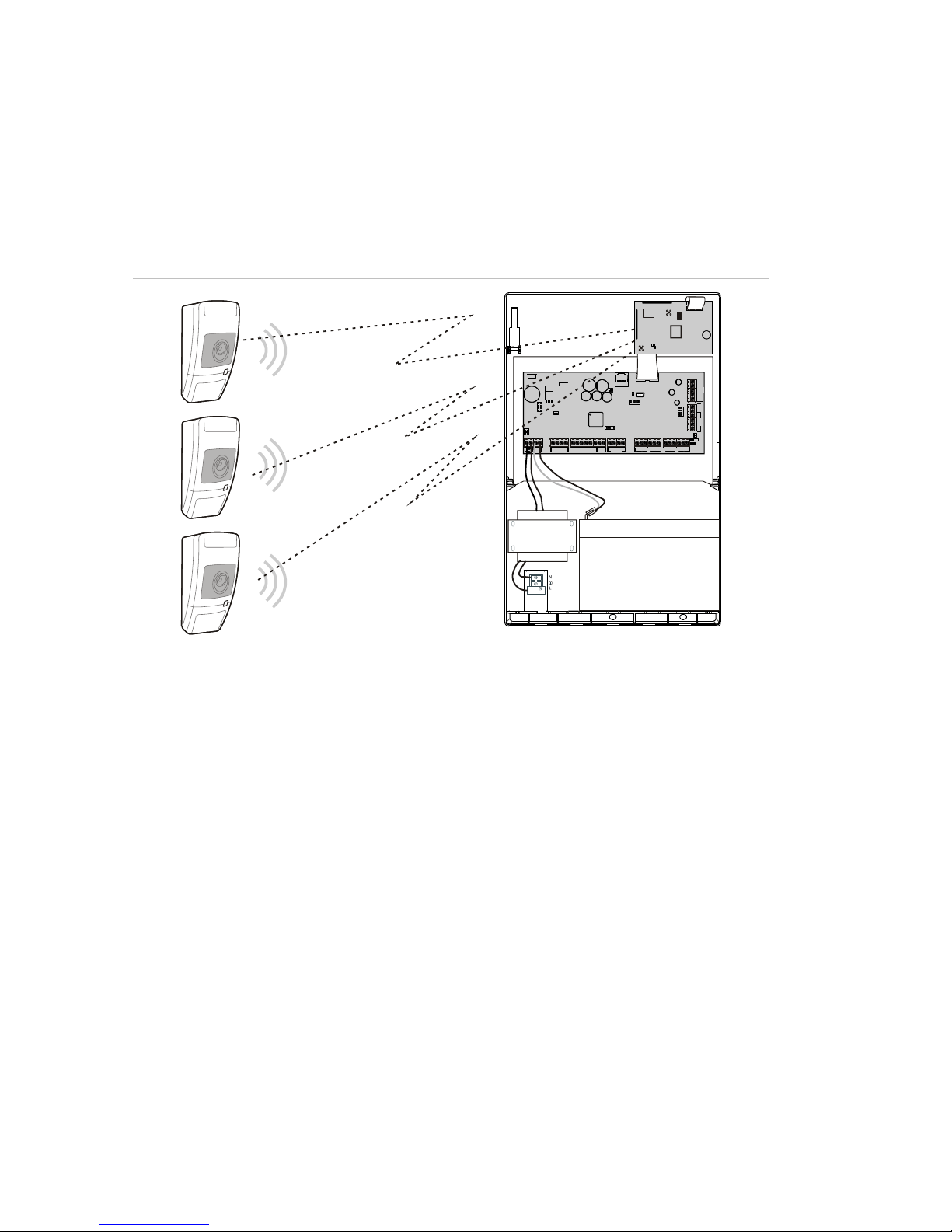
System structure
An Advisor Advanced system can have one ATS1238 wireless PIR camera
expander mounted inside of the panel housing, and connected to the MI bus.
See “ATS1238 expander” on page 4 for details.
The system with a wireless PIR camera expander can have up to 8 wireless PIR
cameras programmed.
Figure 1: System structure
Camera activation
The system with a wireless PIR camera expander can have up to 8 wireless PIR
cameras programmed. Each camera can be activated in case of the following
events:
• Activation of one of 4 assigned zones. Zones are assigned in menu “4.3.n.2
Pics by zone” on page 11.
In this case camera event type depends on the zone type. See “Camera
event types” on page 3.
• Activation of a condition filter. The event type is defined for the programmed
filter. See “4.3 Cameras” on page 10.
• Activation of a standard reporting event. See “4.3.n.4 Pics by rep ev” on page
12.
• User command.
• Remote request from configuration software.
The number and the quality of pictures taken depend on the camera event type.
See “Programming menus” on page 7 for details.
Rx
Tx
IP
USB
MI
IP
CON23
CON19
CON12
LK2
CON13
USB
T1
T2
LK3
S3 S4 S5
+
+
S1 C+S2 C T C
+
+
- -
1 C 2 3 C 4 5 C 6 7 C 8
~~+
-
AC
BATT
LC-OUTPUTS
HC-OUTPUTS SIR TMP
AUX POWER
INPUTS
Ax/R1
B/TA/R
EARTH
CTD-
D+
0V
+12V
COMMS
TAMPER
PSTN
ATS1238
ATS1000A
ON
123 4
MI-BUS
MI-BUS
HDR-ANT2
LDRM-ANT1
HDR-ANT1
LDRM-ANT2
( )6
Page 3

PIR Camera Reference Manual 3
Camera event types
There are the following camera event types available.
• Burglar alarm. Generated by alarm, entry/exit, access, 24 H, firedoor and
keybox type zones.
• Fire alarm. Generated by fire zones.
• Panic alarm. Generated by panic zones.
• Medical alarm. Generated by medical zones.
• Tamper alarm. Generated by tamper zones.
• Fault. Generated by technical, transmission fault, aux mains fault and aux
battery fault type zones.
• Custom type 1. Generated by conditional filters of this type.
The types are assigned to conditional filters.
• Custom type 2. Generated by conditional filters of this type.
Event type details are listed in Table 1 below.
Table 1: Camera events and reporting codes
Event type
Activated by zone type [1]
SIA code [2]
Burglar alarm
1. Alarm, 2. Entry/Exit 1, 3. Access, 6. 24H, 13. Fire door,
16. Key box, 18. Entry/Exit 2
BA
Fire alarm
4. Fire
FA
Panic alarm
5. Panic
PA
Medical alarm
10. Medical
MA
Tamper alarm
7. Tamper
TA
Fault
11. Technical, 12. Transmission path fault, 14. Aux mains
fault, 15. Aux batt fault
UA
Custom type 1
Not allowed [3]
Selectable
Custom type 2
Not allowed [3]
Selectable
[1] Zones of particular types do not activate camera. These are 8. Exit terminator, 9. Keyswitch,
17. Eng. reset. When an assigned zone is one of the listed types, it is ignored when active.
[2] If the camera has been activated by a standard reporting event, another event caused by
camera activation does not occur.
Detailed codes and subevent values are described in Advisor Advanced Programming
Manual.
[3] Custom type events can only be activated by condition filters.
Each of these types can be configured in “2.2.2.n.4.09.1 Pic settings” on page 7.
Depending on camera event type, the camera can be programmed to take a
single picture or a series of pictures, in low or high resolutions.
Page 4
4 PIR Camera Reference Manual
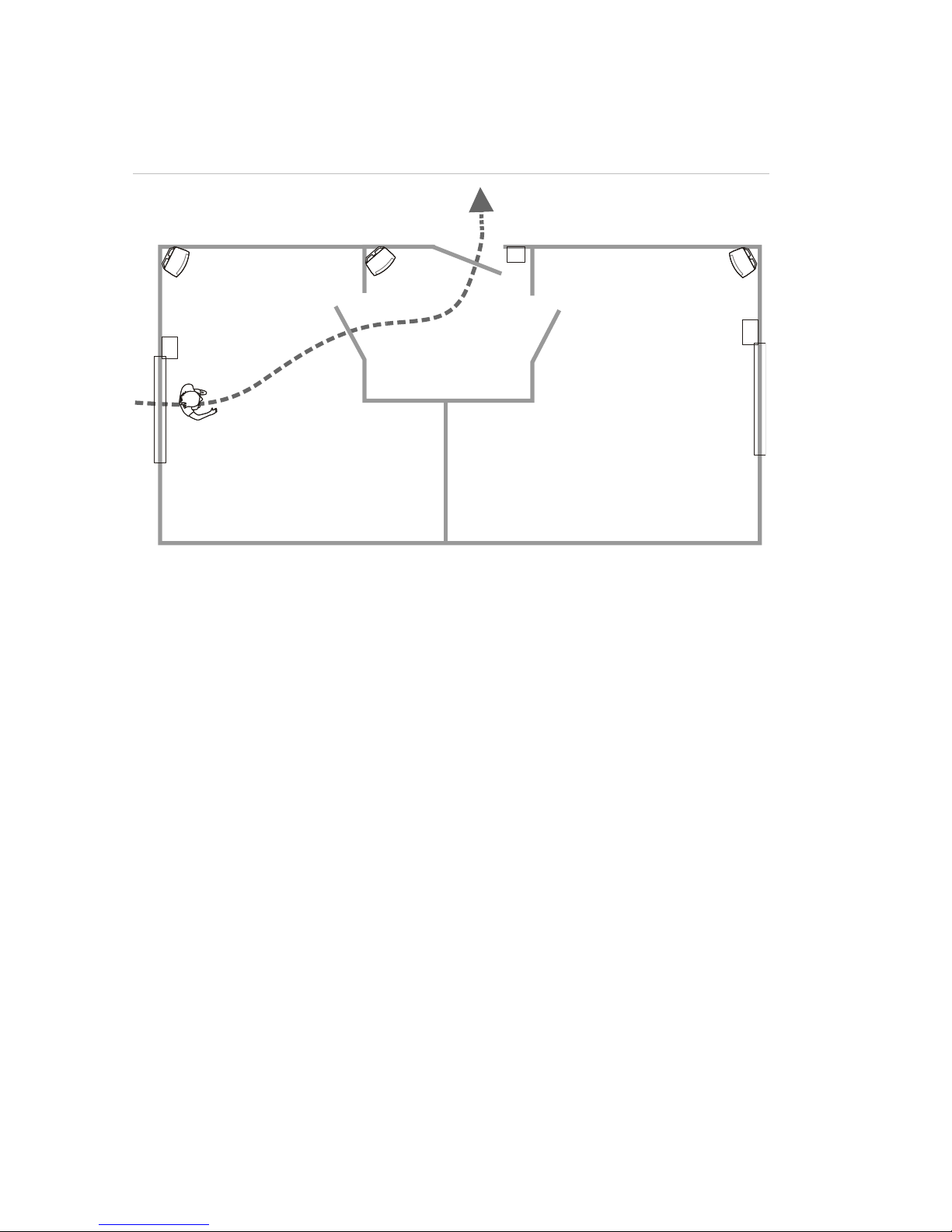
Application example
Figure 2 below shows an example of wireless PIR camera application.
Figure 2: Application example
(1) Intrusion zone 3, PIR camera 3
(2) Access zone 2, PIR camera 2
(3) Entry/exit zone 1, door contact
(4) Intrusion zone 5, PIR camera 5
(5) Intrusion zone 4, door/window sensor
(6) Intrusion zone 6, door/window sensor
In the example above, camera 3 (item 1) is activated not only by built-in PIR
camera, but also by zones 4 (item 5) and 2 (item 2). This makes possible taking
pictures of the intruder escape path.
ATS1238 expander
PIR Camera expands Advisor Advanced control panel inputs with 868 MHz AM
wireless transmitter sensors.
ATS1238 also supports wireless PIR cameras. For intrusion alarm events the
868 MHz AM connection is used. The additional camera video verification
functionality uses the 2.4 GHz connection.
Fob buttons can be programmed to set and unset premises, or to control relays.
For example, a fob can be used to open and close a garage door remotely.
ATS1238 supports maximum 8 wireless PIR cameras and sensors (total of 32)
and 16 fobs. ATS1238 expands the panel with 32 zones.
Note: Only one ATS1238 can be connected to the control panel. Install ATS1235
expanders to increase number of sensors and fobs.
ATS1238 requires the following ATS Advanced control panel firmware versions:
MR_022.022.0110 or later.
(1) (2)
(3)
(4)
(5)
(6)
Page 5

PIR Camera Reference Manual 5
The wireless expander is powered from the Advisor Advanced control panel MI
bus.
Installation
ATS1238 is mounted inside Advisor Advanced large plastic housing.
WARNING: Electrocution hazard. To avoid personal injury or death from
electrocution, remove all sources of power and allow stored energy to discharge
before installing or removing equipment.
Refer to ATS1238 Advanced Wireless DGP Installation Sheet for details on
installation and address setting.
Programming
The ATS1238 expander is programmed using the Advisor Advanced control
panel programming menu. Refer to Advisor Advanced Programming Manual for
details.
To activate the expander, use the Devices submenu of the Advisor Advanced
programming menu. See “Programming menus” on page 7 for details.
Wireless PIR camera
Description
A wireless PIR camera is a wireless PIR detector with a camera built-in. The
camera can be programmed to take pictures in case of activation of associated
zones, conditional filters, as well as by manual activation or remote requests.
See “Camera activation” on page 2 for more details.
Installation
The PIR camera is intended to be mounted on walls but can also be mounted on
ceilings by using a mounting bracket.
Use the following guidelines to determine the best location to install the PIR
camera.
• Mount the PIR camera so the expected movement of an intruder is across the
detection pattern.
• Mount the PIR camera at a stable surface at a height between 1.8 m and
3.0 m from the floor.
• Do not mount the PIR camera within 0.5 m of metallic objects or within 1.5 m
of fluorescent lights.
• Do not place objects in front of the PIR camera that may prevent a clear line
of sight.
• Place PIR cameras at least 1 m apart from each other.
Avoid potential causes of instability, such as:
• Direct sunlight on the detector
Page 6

6 PIR Camera Reference Manual
• Heat sources within the detector field of view
• Strong air draughts onto the detector
• Animals in the field of view
• Obscuring the detector field of view with large objects, such as furniture
We recommend that the PIR camera is regularly walk tested and checked at the
control panel.
Programming
Wireless PIR camera is programmed using the Advisor Advanced programming
menu.
How to program a camera:
1. Program the wireless PIR camera expander. See “ATS1238 expander” on
page 4 for more details.
2. Program a wireless PIR camera as a wireless PIR detector. See
“Programming menus specific for PIR camera” on page 7 for more details.
If the detector is programmed successfully, the appropriate camera is created
automatically. The created camera number is equal to the zone number of the
wireless PIR detector.
3. Program the camera options. See “4.3 Cameras” on page 10.
4. Assign zones to the camera. Choose up to four zones. The camera is useful if
its field of view covers these zones or possible burglar escape paths from
there.
By default, the first assigned zone is the zone of the wireless detector built in
the configured wireless PIR camera.
5. If necessary, program conditional event filters that activate the camera.
6. If necessary, program reporting events that activate the camera.
Troubleshooting
Camera busy message
Camera busy message may appear when a camera or a wireless expander do
not respond to a request because one the following operations is currently in
progress:
• Erasing picture memory on the wireless expander
• Running RSSI test
• Running RF diagnostic test
• Running range test
• Setting camera mode (for example, unsetting the system
• Taking pictures according to other request
• Running walk test
• Learning in camera
• Updating current state (occurs for 2 to 3 s every 17 minutes)
Page 7

PIR Camera Reference Manual 7
Solution: repeat the request after a delay of a few seconds.
Camera error message
Camera error message appears due to one of the following states:
• Processing another request for longer than 20 s (for example, reporting
pictures for previous request for this camera)
• Communication failed
Solutions:
• Repeat the request in a few minutes
• Verify power supply
• Verify communication quality
See also “Camera diagnostics” on page 16.
Programming menus specific for PIR camera
2.1 Installed remote devices
>Rkp R--x--- Exp m--?---
The Installed remote devices screen shows the status of all connected remote
keypads (1 to 8) and expanders (1 to 7).
The following statuses are shown if an ATS1238 expander is connected to the MI
bus:
• M: ATS1238 is online and configured (polled)
• m: ATS1238 is online, but not configured (new)
• c: ATS1238 is online, but its address is in conflict with another expander
To configure an expander shown as “m”, press Enter. Otherwise, solve the
connection problem.
2.2.2.n.4.09 Pic options
1>Pic settings
>>>
This menu is specific for systems with wireless PIR camera expanders.
2.2.2.n.4.09.1 Pic settings
1>Burglar set.
>>>
The menu allows you to configure photo recording options separately for the
following camera event types:
• Burglar alarms
• Fire alarms
• Panic alarms
• Medical alarms
Page 8

8 PIR Camera Reference Manual
• Tamper alarms
• Faults: Device faults and technical alarms
• Custom type 1: User programmable type 1
• Custom type 2: User programmable type 2
See also “Camera event types” on page 3.
2.2.2.n.4.09.1.1 Burglar settings
1>Pic amount
1
Enter the BA settings menu to configure picture settings for burglar alarms.
2.2.2.n.4.09.1.1.1 Pic amount
1 Pic amount
>1<
Set the number of pictures taken after an event of the selected type occurs.
Allowed range is 1 to 30. The delay between pictures is set in “2.2.2.n.4.09.1.1.2
Frame rate” below.
2.2.2.n.4.09.1.1.2 Frame rate
2 Frame rate
>500 ms<
The menu defines a frequency of taking pictures on an event of the selected
type.
The menu is only available if “2.2.2.n.4.09.1.1.1 Pic amount” above value is
larger than 1.
The allowed values are 500 ms, 1 s, 5 s, 15 s, 60 s.
2.2.2.n.4.09.1.1.3 Pic quality
3 Pict quality
>QVGA<
The option defines resolutions of pictures taken upon an event of the selected
type. The following options are available:
• QVGA: 320 x 240 pixels
• VGA: 640 x 480 pixels
• QVGA and VGA: Two pictures at once, one in low resolution, and one in high.
2.2.2.n.4.09.1.2 Fire settings
2.2.2.n.4.09.1.3 Panic settings
2.2.2.n.4.09.1.4 Medical settings
2.2.2.n.4.09.1.5 Tamper settings
Page 9

PIR Camera Reference Manual 9
2.2.2.n.4.09.1.6 Fault settings
See “2.2.2.n.4.09.1.1 Burglar settings” on page 8.
2.2.2.n.4.09.1.7 Custom type 1
2.2.2.n.4.09.1.8 Custom type 2
Custom types are used with condition filters for camera activation.
See “2.2.2.n.4.09.1.1 Burglar settings” on page 8.
2.2.2.n.4.09.2 Show pic mem
Pictures: 12
Left sp for: 123
Free SP: 3,0MB
Total SP: 4,0MB
The informational screen shows a pictures number currently stored in the
wireless PIR camera expander as well as available memory.
2.2.2.n.4.09.3 Pic auto deletion
3 Pic auto del
>1 day<
The value defines whether the pictures stored in the wireless PIR camera
expander will be deleted automatically after a chosen period of time (in days).
The allowed range is 1 to 120 days. 0 or Off mean that pictures are never deleted
automatically. Users must control the available memory and remove pictures
manually.
2.2.2.n.4.09.4 Delete pics
4 Delete pics
>Cancel<
Choose OK and press Enter to remove all stored pictures from the wireless PIR
camera expander.
4.1.0 Add zone
To add a wireless PIR camera, follow these steps.
1. Select zone location.
1>Expander 1
2 Expander 2
2. Choose Sequential mode and press Enter.
Learn mode
>Sequential<
Page 10

10 PIR Camera Reference Manual
3. Choose an input number.
Input number
> 2<
4. Remove the PIR camera from mounting plate to activate it.
INFO
Tamper RF 1
If an error occurs, the keypad shows an error message and beeps seven times.
Example:
ERROR
RF duplicate
The error can occur, for example, when you try to learn a device, which is
already programmed in the wireless expander. See “Camera unregistering”
below for details.
Next you are asked if you want to edit the new zone.
Edit zone?
>No<
Chose Yes and press Enter to edit zone settings.
You are also asked to edit settings of the created camera.
Edit camera?
>No<
If the device is programmed successfully, the keypad beeps twice.
Camera unregistering
Note: Once learned, the PIR camera cannot be learned on another wireless
expansion without prior unregistering from a previous expansion. To unregister
the PIR camera, revert it to the factory settings by following these steps:
1. Remove the PIR camera from mounting plate.
2. Insert factory setting jumper.
3. Remove batteries.
4. Wait 10 seconds.
5. Insert batteries.
6. Wait approximately 3 seconds until the PIR camera powers up.
7. Remove the factory setting jumper and mount the PIR camera.
After that, the PIR camera is defaulted and ready for learning in.
4.3 Cameras
17>Camera 17
18 Camera 18
The menu allows you to configure camera modules in wireless PIR cameras.
Page 11

PIR Camera Reference Manual 11
4.3.n Select camera
1>Camera name
Camera 17
Select an appropriate camera to configure.
4.3.n.1 Camera name
1 Camera name
>Camera 17 <
Enter camera name.
4.3.n.2 Pics by zone
1>Zone 17
2 Zone 2
Choose 1 to 4 zones that can trigger the camera when active.
By default, the first zone assigned is the zone with PIR detector of this wireless
PIR camera.
Choose a zone position to assign a zone, or an existing zone to remove it from
the associated zone list.
4.3.n.3 Pics by filter
1>Filter 1
>>>
Additionally to the zones listed in “4.3.n.2 Pics by zone” above, there can be up
to two condition filters that also trigger the camera.
4.3.n.3.m Select filter
1>Filter 1
Not used
Select one of two filters to configure.
4.3.n.3.m.1 Choose filter
00>Not used
01 Internal sire
Choose a filter that activates the selected camera.
4.3.n.3.m.2 Event type <n>
2 Event type 1
>Burglar<
Define a type of the condition filter chosen in “4.3.n.3.m Select filter” above.
The available filter types are listed in “Camera event types” on page 3.
Page 12

12 PIR Camera Reference Manual
4.3.n.3.m.3 Report as
3 Report as
>Not used<
If the filter has a custom type, it is necessary to assign a reporting event, which
occurs when the filter becomes active.
Notes
• After you leave this menu, the event is shown as a reporting code in SIA
format.
• Only particular reporting events are available.
4.3.n.4 Pics by rep ev
1>Rep. event 1
Not used
The camera can be also triggered by a selected reporting event.
4.3.n.4.m Select event
1 Rep. event 1
>Not used<
Select one of two reporting events to configure.
Choose an event that activates the selected camera.
Notes
• After you leave this menu, the event is shown as a reporting code in SIA
format.
• Only particular reporting events are available.
4.3.n.5 Isolated
5 Isolate
>No<
When the camera is isolated, it does not take pictures. Also, pictures cannot be
sent to the panel.
4.3.n.6 Max pics 24h
6 Max pics 24h
>Infinity<
Maximum picture number defines how many pictures can be taken by the
camera during 24 hours period of set or unset state.
The counter is reset when the area changes its set state.
The allowed range is 1 to 999, or 0 (infinity), which means unlimited number of
pictures.
If the limit is reached, the camera switches off and an appropriate event is
recorded in the log.
Page 13

PIR Camera Reference Manual 13
4.3.n.7 Remote pics
7 Remote pics
>Yes<
If remote picture triggering is enabled, you can take a picture remotely, using
configuration software.
4.3.n.8 Test pic to CS
1>CS 1
------------
The command allows you to take picture and send it to a selected central station.
Choose a central station to send the picture.
Calling CS 1...
Transmitting
The current picture transmission status is shown in the bottom line of the screen.
9.1.n.4.4 Vid dest port
4 Vid dest port
>9000<
The destination port is used to send the pictures to a host.
9.1.n.4.5 Encryption
5 Encryption
>No<
If the Encryption option is set to Yes, the pictures are sent encrypted with AES
algorithm.
9.3.n.10 Max Pics 24h
10 Max Pics 24h
> <
You can limit the maximum number of pictures sent to users via GPRS or IP
transmission path during a 24-hour period.
If the limit is reached, further picture requests are denied by the system and an
appropriate event is recorded in the log.
There is no limit for pictures if this value is set to 0.
Basic user commands
The following main commands are available in Advisor Advanced user menu:
• Isolate camera. See “1.2.n.4 Isolate” on page 14.
• Allow remote camera control. See “1.2.n.6 Remote pics“ on page 14.
• Take picture. See “1.2.n.7 Test pic to CS” on page 15.
• Delete pictures. See “1.3 Delete pics” on page 15.
• Perform a walk test. See “8.2 Walk test” on page 15.
Page 14

14 PIR Camera Reference Manual
• Take a picture with a fob. Ensure the fob is programmed for making picture by
using an appropriate condition filter. See “4.3.n.3 Pics by filter” on page 11.
For more information, see Advisor Advanced Programming Manual.
User menus
The following commands are available in Advisor Advanced user menu:
1.2 Camera menu
17>Camera 17
18 Camera 18
Use camera menu to take pictures manually.
Select an appropriate camera.
1.2.n Select camera
4>Isolate
No
Select an appropriate camera to configure.
1.2.n.4 Isolate
4 Isolate
>No<
When the camera is isolated, it does not take pictures. Also, pictures cannot be
sent to the panel.
1.2.n.5 Max pics 24h
5 Max pics 24h
>Infinity<
Maximum picture number defines how many pictures can be taken by the
camera during 24 hours period of set or unset state.
The counter is reset when the area changes its set state.
The allowed range is 1 to 999, or 0 (infinity), which means unlimited number of
pictures.
If the limit is reached, the camera switches off and an appropriate event is
recorded in the log.
1.2.n.6 Remote pics
09 Remote pics
>Yes<
If remote picture triggering is enabled, you can take a picture remotely, using
configuration software.
Page 15

PIR Camera Reference Manual 15
1.2.n.7 Test pic to CS
1>CS 1
------------
The command allows you to take picture and send it to a selected central station.
Choose a central station to send the picture.
Calling CS 1...
Transmitting
The current picture transmission status is shown in the bottom line of the screen.
1.3 Delete pics
1>Expander 1
------------
Delete all pictures from the wireless PIR camera expander.
Select expander, then select OK and press Enter to remove all pictures from the
selected expander.
8.2 Walk test
Walk test
in progress
Walk test allows the user to test all detectors in the selected areas.
To perform the walk test:
1. Enter the menu.
The display lists all zones to be tested.
1>Zone 1
Need Active
2. Walk along all detection points and make sure the detector is activated either
by walking in front of it or by opening a door or window.
Each activated zone is removed from the list on the display.
3. Return to the keypad and verify the result.
If the test is passed, the following message is displayed:
Walk test OK
Press Enter
Otherwise, there still is a list of untested zones. Contact the installer if you are
unable to pass the walk test.
See “Walk test” on page 16 for more details.
Page 16

16 PIR Camera Reference Manual
Camera diagnostics
The following menus are available for camera diagnostics:
• RF signal diagnostics. See “1.2.1.3 RF RSSI test” below.
• Camera range test. See “1.2.1.5 Camera range test” below.
1.2.1.3 RF RSSI test
1>Expander 1
2 Expander 5
Select the input location first.
Enter the physical input number on this location. The screen shows LDR data. .
Zone 1
-44dBm [IIII ]
Press Right to toggle between LDR and HDR receiver data, or wait 2 seconds for
the screen to scroll automatically.
Zone 1
QI=50% [III ]
For more information on the communication quality, refer to the appropriate
wireless expander manual.
1.2.1.5 Camera range test
17 Camera 17
18 Camera 18
Range test allows you to verify wireless PIR camera signal reception.
Select a camera to activate range test.
Camera 17
In range test
In this mode, selected wireless PIR cameras show the reception quality with
alarm LED colour:
• Green: Good signal
• Orange: Medium signal
• Red: Weak signal
The LED follows the weakest communication link of LDR and HDR.
For more information on the communication quality, refer to the appropriate
wireless PIR camera expander manual.
Walk test
During walk test wireless PIR camera indicator performs the following functions:
• PIR activation results in 3 seconds red indication.
• Trouble results in 3 seconds orange indication.
Page 17

PIR Camera Reference Manual 17
During walk test pictures are taken and sent to the ATS1238 expander. Installer
can review the pictures afterwards via configuration software.
The detector does not enter the 3 minute sleep mode during walk test.
Page 18

18 PIR Camera Reference Manual
 Loading...