

Page 1

NS4702-24P-4X Managed
Switch User Manual
P/N 1073388-EN • REV A • ISS 08FEB18
Page 2

Copyright
©
2018 United Technologies Corporation.
Interlogix is part of UTC
Corporation
Trademarks and patents
Trade names used in this document may be trademarks or registered trademarks of the
manufacturers or vendors of the respective products.
Manufacturer
Interlogix
2955 Red Hill Avenue, Costa Mesa, CA 92626
Authorized EU manufacturing representative:
UTC Fire & Security B.V.
Kelvinstraat 7, 6003 DH Weert, The Netherlands
Version
This document applies to
FCC compliance
This device complies with part 15 of the FCC Rules. Operation is subject to the following
two conditions: (1) This device may not cause harmful interference, and (2) this device
must accept any interference received,
operation.
FCC compliance
Class A: This equipment has been tested and found to comply with the limits for a Class
A digital device, pursuant to part 15 of the FCC Rules. These limits are designed to
provide
operated in a commercial environment. This equipment generates, uses, and can radiate
radio frequency energy and, if not installed and used in accordance with the instruction
manual,
equipment in a residential area is likely to cause harmful interference in which case the
user will be required to correct the interference at his own expense.
Canada
This Class A
Cet appareil numérique de la classe A est conforme à la norme CAN ICES
(A)/NMB
ACMA compliance
Notice!
radio interference in which case the user may be required to take adequate measures.
Certification
EU directives
This product and
comply therefore with the applicable
EMC Directive 2014/30/EU, the RoHS Directive 2011/65/EU.
2012/19
Products marked with this symbol cannot be disposed of
as unsorted municipal waste in the European Union. For proper
product to your local supplier upon the purchase of equivalent new equipment, or
dispose of it at designated collection points. For more information see:
www.recyclethis.info.
Product warnings and
disclaimers
THESE PRODUCTS ARE
QUALIFIED PROFESSIONALS. UTC FIRE & SECURITY CANNOT PROVIDE ANY
ASSURANCE THAT ANY PERSON OR ENTI TY BUYING ITS PRODUCTS,
INCLUDING ANY “AUTHO RIZED DEALER” OR “AUTHORIZED RESELLER”, IS
PROPERLY TRAINED OR EXPERIENCED
SECURITY RELATED PRODUCTS
For more information on warranty disclaimers and product safety information, please
check
Contact information and
manuals
For contact information go to:
To get translations for this and other product manuals go to:
www.firesecurityproducts.com
Climate, Controls & Security, a unit of United Technologies
. All rights reserved.
NS4702-24P-4X.
-5923, USA
including interference that may cause undesired
reasonable protection against harmful interference when the equipment is
may cause harmful interference to radio communications. Operation of this
digital apparatus complies with CAN ICES-003 (A)/NMB-3 (A).
-003
-3 (A).
This is a Class A product. In a domestic environment this product may cause
- if applicable - the supplied accessories too are marked with "CE" and
harmonized European standards listed under the
/EU (WEEE directive):
recycling, return this
INTENDED FOR SALE TO AND INSTALLATION BY
.
www.firesecurityproducts.com/policy/product-warning/ or scan the following code:
www.interlogix.com or www.firesecurityproducts.com.
.
TO CORRECTLY INSTALL FIRE AND
Page 3

Content
Important information 3
Chapter 1 Introduction 4
Package contents 4
Product description 5
Product features 13
Product specifications 17
Chapter 2 Installation 20
Hardware description 20
Chapter 3 Switch management 29
Requirements 29
Management access overview 29
Administration console 30
Web management 32
SNMP-based network management 32
Smart discovery utility 33
Chapter 4 Web configuration 34
Main web page 35
System 36
DHCP server 63
UDLD 74
Simple Network Management Protocol (SNMP) 76
Port management 88
Link aggregation 97
VLAN 105
Spanning Tree Protocol (STP) 132
Multicast 149
Quality of Service (QoS) 174
Access Control Lists (ACL) 199
Authentication 212
Security 247
MAC address table 264
LLDP 268
Network diagnostics 282
Loop protection 286
RMON 288
Ring 297
Power over Ethernet (PoE) 310
Port identification 324
LCD 324
NS4702-24P-4X Managed Switch User Manual 1
Page 4

Chapter 5 Switch operation 326
Address table 326
Learning 326
Forwarding and filtering 326
Store-and-forward 326
Auto-negotiation 327
Chapter 6 PoE overview 328
What is PoE? 328
PoE system architecture 328
Chapter 7 Troubleshooting 330
Appendix A Networking connection 331
Glossary 333
2 NS4702-24P-4X Managed Switch User Manual
Page 5

Important information
Limitation of liability
To the maximum extent permitted by applicable law, in no event will UTCFS be liable
for any lost profits or business opportunities, loss of use, business interruption, loss of
data, or any other indirect, special, incidental, or consequential damages under any
theory of liability, whether based in contract, tort, negligence, product liability, or
otherwise. Because some jurisdictions do not allow the exclusion or limitation of liability
for consequential or incidental damages the preceding limitation may not apply to you.
In any event the total liability of UTCFS shall not exceed the purchase price of the
product. The foregoing limitation will apply to the maximum extent permitted by
applicable law, regardless of whether UTCFS has been advised of the possibility of
such damages and regardless of whether any remedy fails of its essential purpose.
Installation in accordance with this manual, applicable codes, and the instructions of the
authority having jurisdiction is mandatory.
While every precaution has been taken during the preparation of this manual to ensure
the accuracy of its contents, UTCFS assumes no responsibility for errors or omissions.
Advisory messages
Advisory messages alert you to conditions or practices that can cause unwanted
results. The advisory messages used in this document are shown and described below.
WARNING: Warning messages advise you of hazards that could result in injury or loss
of life. They tell you which actions to take or to avoid in order to prevent the injury or
loss of life.
Caution: Caution messages advise you of possible equipment damage. They tell you
which actions to take or to avoid in order to prevent damage.
Note: Note messages advise you of the possible loss of time or effort. They describe
how to avoid the loss. Notes are also used to point out important information that you
should read.
NS4702-24P-4X Managed Switch User Manual 3
Page 6

Chapter 1
Introduction
The IFS NS4702-24P-4X 24-port 10/100/1000Mbps 802.3at PoE + 4-Port 10G SFP+
managed switch with hardware layer 3 IPv4/IPv6 static routing comes with a multi-port
gigabit ethernet switch, SFP fiber optic connectibility, and robust layer 2 features. The
description of this model is as follows:
L2+ 24-port 10/100/1000Mbps 802.3at PoE
+ 4-port 10G shared SFP+
Managed switch with hardware layer 3 IPv4/IPv6 static routing
Unless specified, the term “managed switch” mentioned in this user manual refers to
the NS4702-24P-4X.
Package contents
Open the box of the managed switch and carefully unpack it. The box should contain
the following items:
The managed switch × 1
RJ45 to RS232 cable x 1
Rubber feet x 4
Two rack-mounting brackets with attachment screws x 1
Power cord x 1
SFP dust-proof cap x 4
If any of these are missing or damaged, contact your dealer immediately. If possible,
retain the carton including the original packing materials for repacking the product in
case there is a need to return it to us for repair.
Note: User manuals and install guides are available for download from
www.interlogix.com.
4 NS4702-24P-4X Managed Switch User Manual
Page 7
Chapter 1: Introduction
Product description
PoE+ managed switch with advanced L2+/L4 switching and security
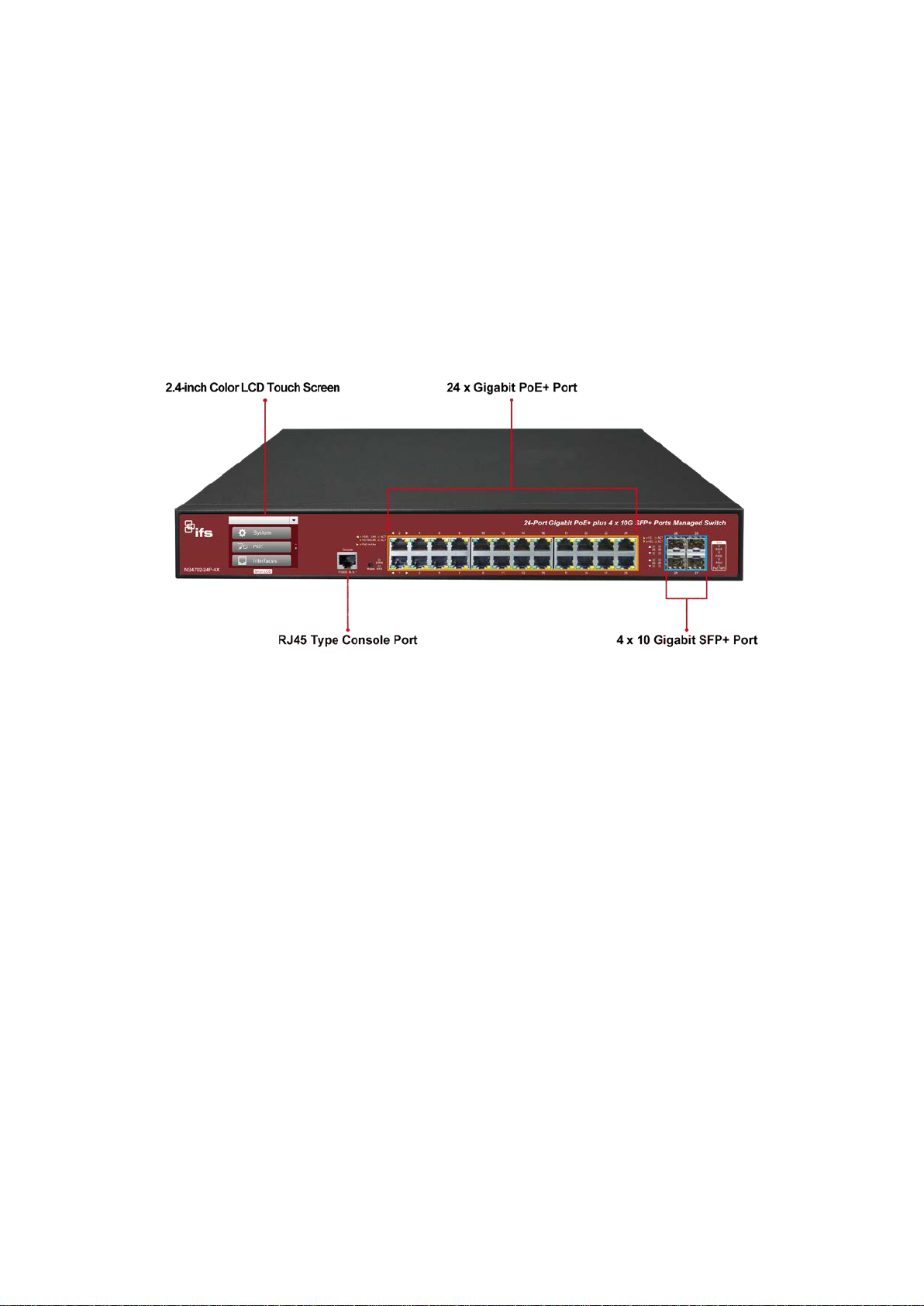
The NS4702-24P-4X is a cost-optimized, 1.25U, Gigabit PoE+ Managed Switch with an
LCD Touch Screen featuring intelligent PoE functions to improve the availability of
critical business applications. The managed switch provides IPv6/IPv4 dual stack
management and a built-in L2+/L4 Gigabit switching engine along with 24
10/100/1000BASE-T ports featuring 30 W PoEat and four additional 10 gigabit SFP+
ports. With a total power budget of up to 400 W for different kinds of PoE applications,
the managed switch provides a quick, safe, and cost-effective PoE+ network solution
for small businesses and enterprises.
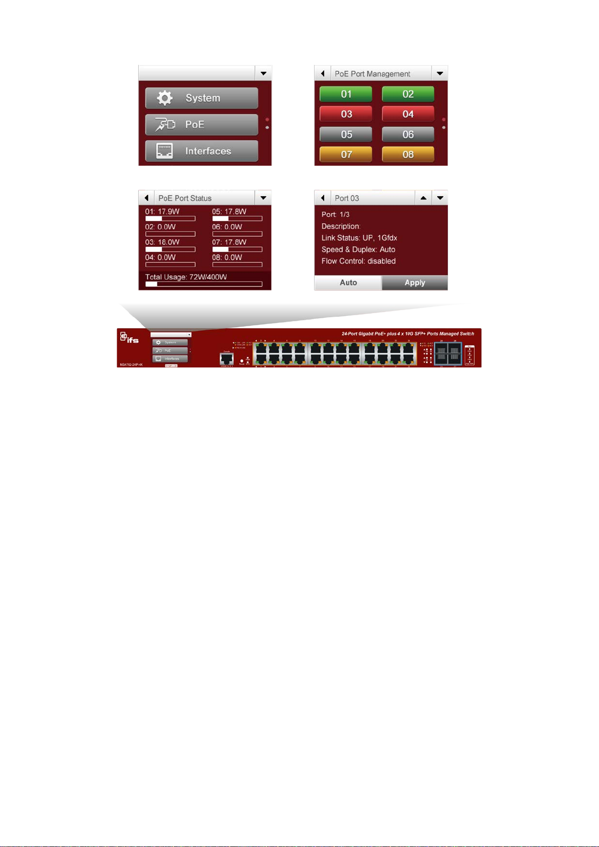
Smart and Intuitive LCD Control
The smart LCD PoE managed switch provides an intuitive touch panel on its front panel
that facilitates the Ethernet PoE PD (powered device) management that greatly
promotes management efficiency in large-scale networks such as enterprises, hot els,
shopping malls, government buildings, and other public areas. They also feature the
following special management and status functions:
• IP address, VLAN and QoS configuration
• PoE management and status
• Port management and status, and SFP information
• Troubleshooting: cable diagnostic and remote IP ping
• Maintenance: reboot, factory default and save configuration
NS4702-24P-4X Managed Switch User Manual 5
Page 8
Chapter 1: Introduction
Built-in unique PoE functions for powered devices management
As a managed PoE switch for surveillance, wireless, and VoIP networks, the NS470224P-4X features the following special PoE management functions:
• PD alive check
• Scheduled power recycling
• PoE schedule
• PoE usage monitoring
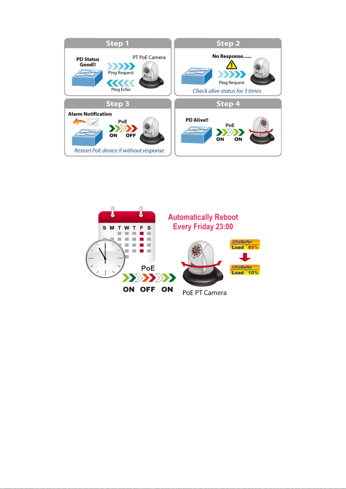
Intelligent powered device alive check
The managed switch can be configured to monitor connected PD status in real time via
a ping action. After the PD stops working and responding, the managed switch
resumes the PoE port power and puts the PD back to work. The managed switch
greatly enhances the network reliability through the PoE port resetting the PD’s power
source and reducing the administrator management burden.
6 NS4702-24P-4X Managed Switch User Manual
Page 9
Chapter 1: Introduction
Scheduled power recycling
The managed switch permits each of the connected PoE IP cameras or PoE wireless
access points to reboot at a specified time each week. This reduces the chance of IP
camera or AP crashes resulting from buffer overflow.
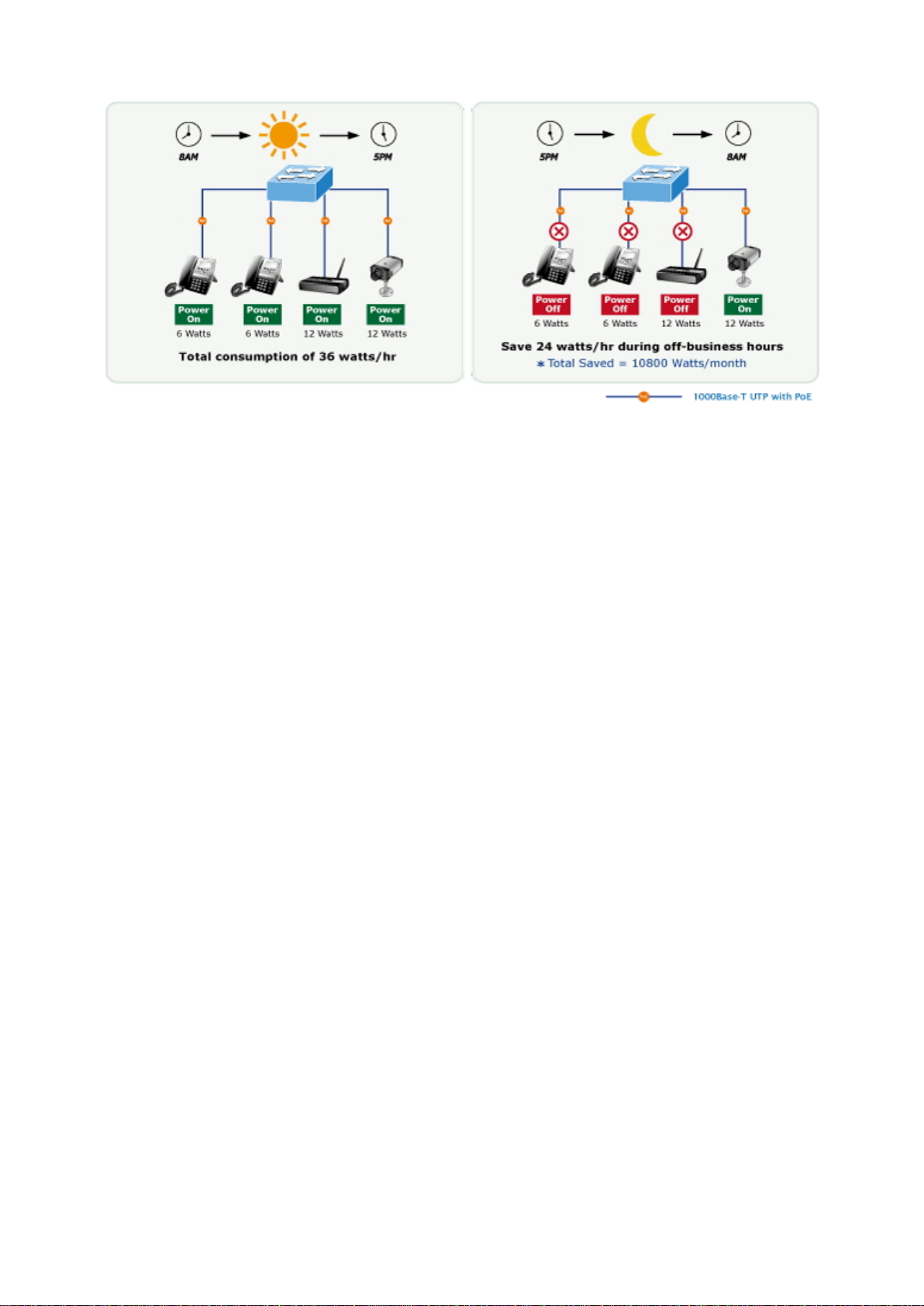
PoE schedule for energy saving
Under the trend of energy saving worldwide and contributing to environmental
protection, the managed switch can effectively control the power supply in addition to
its capability of provideing high Watt power. The “PoE schedule” function helps you to
enable or disable PoE power feeding for each PoE port during specified time intervals,
and is a powerful function to help SMBs or enterprises save power and money. It also
increases security by powering off PDs that should not be in use during non-business
hours.
NS4702-24P-4X Managed Switch User Manual 7
Page 10
Chapter 1: Introduction
PoE usage monitoring
Using the power usage chart in the web management interface, the managed s witc h
allows the administrator to monitor the status of the power usage of the connect ed PDs
in real time, thus enhancing the management efficiency of the facilities.
Cost-effective 10 Gbps uplink capacity
10G Ethernet is a big leap in the evolution of Ethernet. The four 10G SFP+ slots of the
managed switch support dual-speed 10GBASE-SR/LR or 1000BASE-SX/LX, meaning
the administrator has the flexibility to choose a suitable SFP/SFP+ transceiver
according to the transmission distance or the transmission speed required to extend the
network efficiently. This enables SMB networks to achieve the m aximum performance
of 10Gbps in a cost-effective way since the 10GbE interface usually available in a layer
3 switch but layer 3 switch could be too expensive for SMBs.
Environment-friendly, variable fan design for silent operation
The managed switch features a 19-inch metal housing, a low noise design, and an
effective ventilation system. It supports smart fan technology that automatically controls
the speed of the built-in fan to reduce noise and maintain the temperature of the PoE
switch for optimal power output capability. The managed switch operates reliably,
stably, and quietly in any environment without affecting performance.
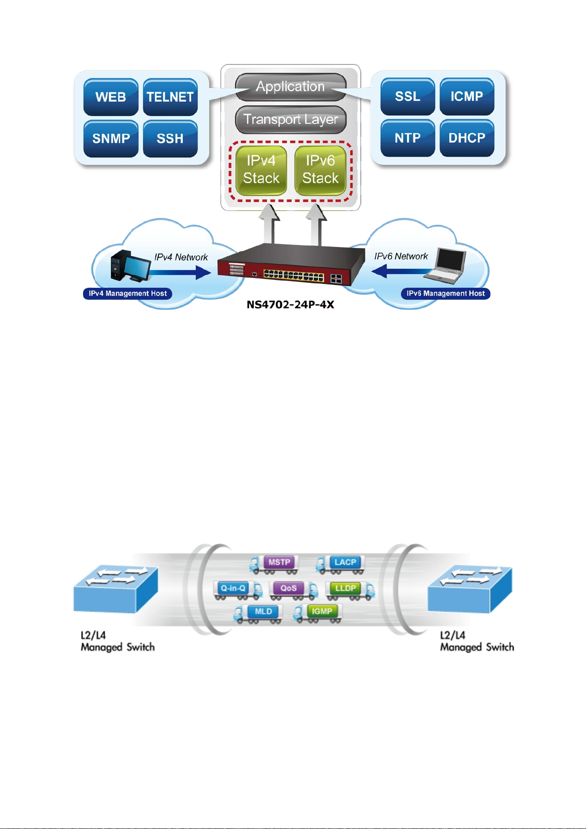
Solution for IPv6 networking
With the IPv6/IPv4 dual stack and other management functions with user-friendly
interfaces, the managed switch is the best choice for IP surveillance, VoIP, and
wireless service providers to deploy the IPv6 network. More importantly, t hey help
SMBs upgrade their network infrastructures to the IPv6 era without any monetary
investment.
8 NS4702-24P-4X Managed Switch User Manual
Page 11
Chapter 1: Introduction
IPv4/IPv6 VLAN routing for secure and flexible management
To help customers stay on top of their businesses, the managed switch not only
provides ultra high transmission performance and excellent layer 2 technologies, but
also a IPv4/IPv6 VLAN routing feature that allows cross over of different VLANs and
different IP addresses for the purpose of having a highly secured, flexible management
and simpler networking application.
Robust layer 2 feature
The managed switch can be programmed for advanced switch management functions
such as dynamic port link aggregation, Q-in-Q VLAN, Multiple Spanning Tree Protocol
(MSTP), layer 2 to layer 4 QoS, bandwidth control, and IGMP / MLD snooping. The
managed switch allows the operation of a high-speed trunk combining multipl e ports. It
consists of a maximum of 14 trunk groups with four ports for each group, and also
supports fail-over.
Powerful security
The managed switch offers a comprehensive layer 2 to layer 4 Access Control List
(ACL) for enforcing security to the edge. It can be used to restrict network access by
denying packets based on source and destination IP address, TCP/UDP ports, or
defined typical network applications. Its protection mechanism also comprises 802.1x
NS4702-24P-4X Managed Switch User Manual 9
Page 12
Chapter 1: Introduction
port-based and MAC-based user and device authentication. With the private VLAN
function, communication between edge ports can be prevented to ensure user privacy.
Enhanced security and traffic control
The managed switch also provides DHCP snooping, IP source gua rd, and dynamic
ARP inspection functions to prevent IP snooping from attack and discard ARP packets
with invalid MAC addresses. The network administrator can now construct highlysecure corporate networks using considerably less time and ef for t than before.
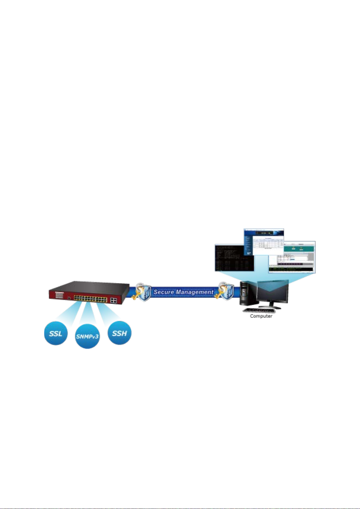
User-friendly secure management
For efficient management, the managed switch is equipped with console, web, and
SNMP management interfaces. With the built-in web-based management int erf ace, the
managed switch offers an easy-to-use, platform-independent management and
configuration facility. The managed switch supports standard Simple Network
Management Protocol (SNMP) and can be managed by any management software
based on the standard SNMP v1 or v2 protocol. For reducing product learning time, the
managed switch offers Cisco-like command via Telnet or console port, and the
customer doesn’t need to learn new commands from these switches. Moreover, the
managed switch offers secure management remotely by supporting SSH, SSL, and
SNMP v3 connections where the packet content can be encrypted at each session.
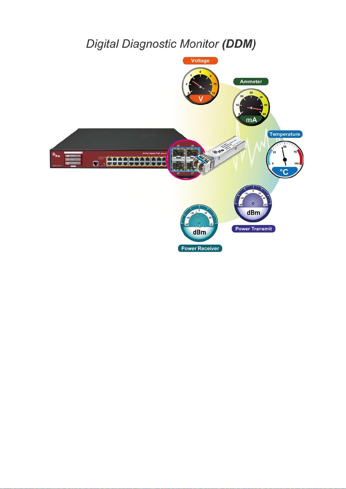
Intelligent SFP diagnostic mechanism
The managed switch series supports a SFP-DDM (Digital Diagnostic M onit or ) function
that can easily monitor real-time parameters of the SFP and SFP+ transceivers, such
as optical output power, optical input power, temperature, laser bias current, and
transceiver supply voltage.
10 NS4702-24P-4X Managed Switch User Manual
Page 13
Chapter 1: Introduction
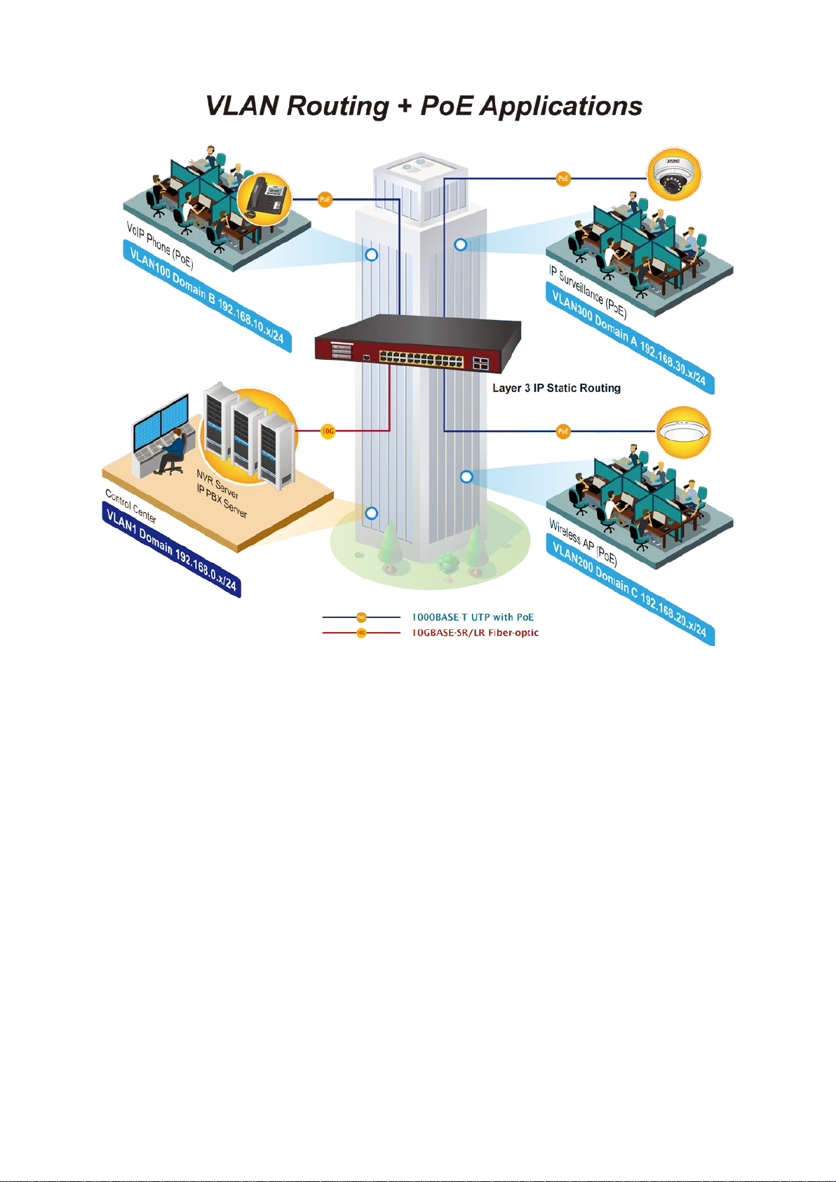
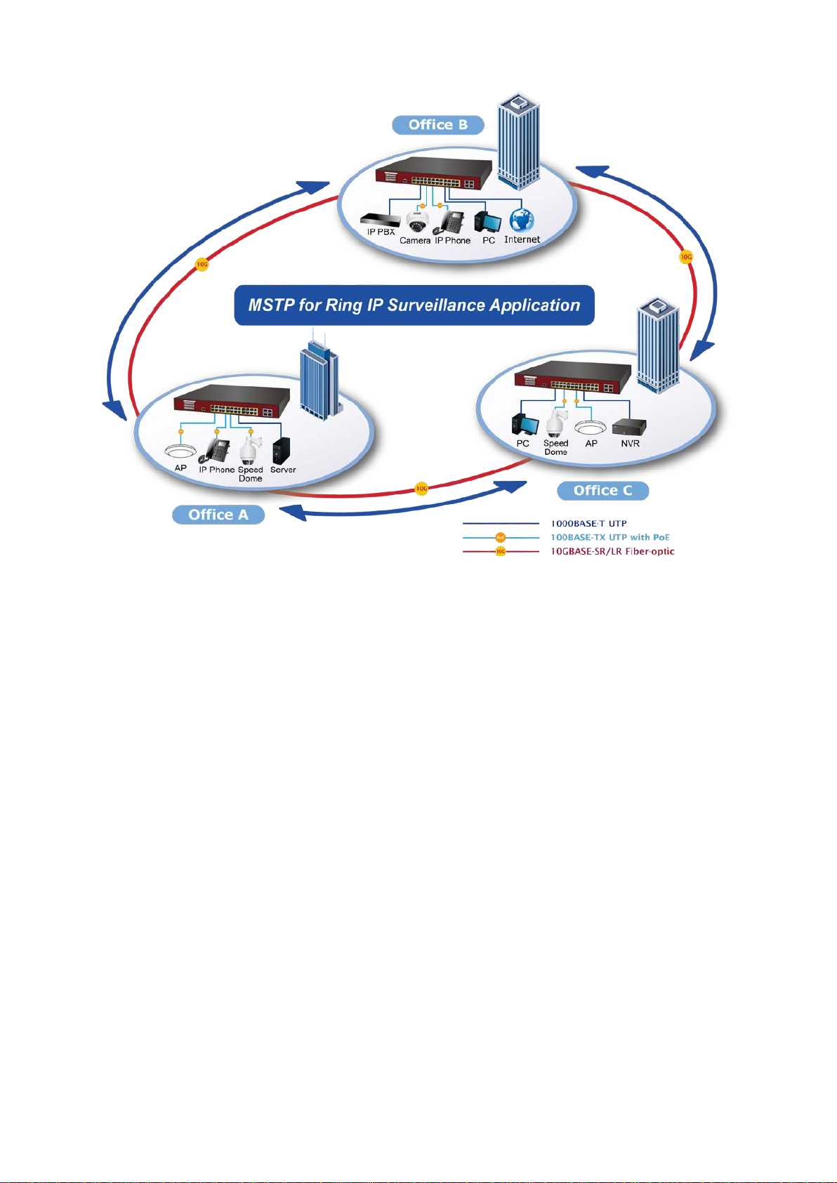
Applications
Layer 2+ VLAN static routing application
The managed switch features IEEE 802.3at PoE+ that combines up to 30 W of power
output per port, and a PoE budget of up to 400 W which can deploy up to 24 PoE PD
devices. It also features a built-in, robust IPv4/IPv6 layer 3 traffic static routing protocol
to ensure reliable routing between VLANs and network segments. The routing protocols
can be applied by VLAN interface with up to 32 routing entries.
NS4702-24P-4X Managed Switch User Manual 11
Page 14
Chapter 1: Introduction
Multiple Spanning Tree Protocol with PoE IP office solution for SMBs and workgroups
The managed switch features strong, rapid self-recovery capability t o prevent
interruptions and external intrusions. It incorporates Multiple Span ning Tr ee Pr ot oc ol
(802.1s MSTP) into the customer’s automation network to enhance system reliability
and uptime. Adopting the IEEE 802.3af/802.3at PoE standard, the managed switch can
directly connect with any IEEE 802.3at PoE end-nodes like PTZ (Pan, Tilt & Zoom)
network cameras and speed dome cameras. The managed switch can easily help
enterprises with the available network infrastructure to build wireless AP, IP camera,
and VoIP systems where power can be centrally controlled.
12 NS4702-24P-4X Managed Switch User Manual
Page 15
Chapter 1: Introduction
Product features
Physical port
• 24-port 10/100/1000BASE-T gigabit RJ45 copper ports with 24-port IEEE802.3af /at
PoE+ injector.
• Four 10GBASE-SR/LR SFP+ slots, compatible with 1000BASE-SX/LX/BX SFP.
• RJ45 console interface for basic switch management and setup.
Power over Ethernet
• Complies with IEEE 802.3at Power over Ethernet Plus/end-span PSE.
• Backward compatible with IEEE 802.3af Power over Ethernet.
• Up to 24 ports of IEEE 802.3af/IEEE 802.3at devices powered.
• Supports PoE power up to 30 W for each PoE port.
• Auto detects powered device (PD).
• Circuit protection prevents power interference between ports.
• Remote power feeding up to 100 meters.
• PoE management:
• Total PoE power budget control
NS4702-24P-4X Managed Switch User Manual 13
Page 16

Chapter 1: Introduction
• Per port PoE function enable/disable
• PoE admin-mode control
• PoE port power feeding priority
• Per PoE port power limitation
• PD classification detection
• Temperature threshold control
• PD alive check
• PoE schedule
Layer 2 features
• Prevents packet loss with back pressure (half-duplex) and IEEE 802.3x pause
frame flow control (full-duplex).
• High performance of Store-and-Forward architecture and runt/ CRC filtering
eliminates erroneous packets to optimize the network bandwidth.
Storm control support:
• Broadcast / Multicast / Unknown-Unicast
Supports VLAN
• IEEE 802.1Q tagged VLAN
• Up to 255 VLANs groups out of 4094 VLAN IDs
• Provider bridging (VLAN Q-in-Q) support (IEEE 802.1ad)
• Private VLAN Edge (PVE)
• Protocol-based VLAN
• MAC-based VLAN
• Voice VLAN
• Management VLAN
Supports STP
• STP, IEEE 802.1D Spanning Tree Protocol
• RSTP, IEEE 802.1w Rapid Spanning Tree Protocol
• MSTP, IEEE 802.1s Multiple Spanning Tree Protocol, spanning tree by VLAN
• BPDU Guard
Supports link aggregation
• IEEE 802.3ad Link Aggregation Control Protocol (LACP)
• Cisco ether-channel (static trunk)
• Maximum 14 trunk groups, up to four ports per trunk group
14 NS4702-24P-4X Managed Switch User Manual
Page 17

Chapter 1: Introduction
• Up to 80Gbps bandwidth (full duplex mode).
Provides port mirror (many-to-1)
Port mirroring to monitor the incoming or outgoing traffic on a particular port
Loop protection to avoid broadcast loops
Layer 3 IP routing features
• Supports a maximum of 32 software static routes and route summarization.
Quality of Service
• Ingress shaper and egress rate limit per port bandwidth control
• Eight priority queues on all switch ports
• Traffic classification:
- IEEE 802.1p CoS
- TOS / DSCP / IP Precedence of IPv4/IPv6 packets
- IP TCP/UDP port number
- Typical network application
• Strict priority and Weighted Round Robin (WRR) CoS policies
• Supports QoS and In/Out bandwidth control on each port
• Traffic-policing policies on the switch port
• DSCP remarking
Multicast
• Supports IGMP snooping v1, v2, and v3
• Supports MLD snooping v1 and v2
• Querier mode support
• IGMP snooping port filtering
• MLD snooping port filtering
• Multicast VLAN Registration (MVR) support
Security
• Authentication
− IEEE 802.1x Port-Based / MAC-Based network access authentication
− Built-in RADIUS client to co-operate with the RADIUS ser v er s
− TACACS+ login users access authentication
− RADIUS / TACACS+ users access authentication
• Access Control List (ACL)
NS4702-24P-4X Managed Switch User Manual 15
Page 18

Chapter 1: Introduction
− IPv4 / IPv6 IP-based ACL
− MAC-based ACL
• Source MAC / IP address binding
• DHCP snooping to filter distrusted DHCP messages
• Dynamic ARP inspection discards ARP packets with invalid MAC addresses to IP
address binding.
• IP source guard prevents IP spoofing attacks.
• IP address access management to prevent unauthorized intruders.
Management
• IPv4 and IPv6 dual stack management
• Switch management interfaces:
− Console / Telnet Command Line Interface
− Web switch management
− SNMP v1, v2c, and v3 switch management
− SSH / SSL secure access
− 2.4-inch color LCD touch screen
• User privilege levels control
• Built-in Trivial File Transfer Protocol (TFTP) client
• System maintenance
- Firmware upload/download via HTTP / TFTP
- Dual images
- Reset button for system reboot or reset to factory default
• Four RMON groups (history, statistics, alarms, and events)
• IPv6 IP address / NTP / DNS management and ICMPv6
• BOOTP and DHCP for IP address assignment
• DHCP relay
• DHCP Option 82
• NTP (Network Time Protocol)
• Link Layer Discovery Protocol (LLDP) and LLDP-MED
• Smart discovery utility for deploy management
• Network diagnostic
− ICMPv6/ICMPv4 remote ping
− Cable diagnostic technology provides the mechanism to detect and report
potential cabling issues
16 NS4702-24P-4X Managed Switch User Manual
Page 19

Chapter 1: Introduction
Hardware Specification
Copper
24
SFP
Four 10GBASE
Compatible with 1000BASE
Console Port
1 x RS
Switch Architecture
Store
Switch
128
Throughput
95.23
Address Table
16
Share
32M bits
Flow Control
IEEE 802.3x
Back pressure for
Jumbo Frame
10
Reset Button
< 5 seconds: System reboot
>
LED
System
PoE Ethernet Interfaces
Ethernet Interfaces
1/10G SFP+ Interfaces
Dimensions (W x D x H)
440 x
Weight
4.64
Power
Max.
Power Requirement
AC
ESD Protection
6K VDC
• SMTP/Syslog remote alarm
• SNMP trap for interface Link Up and Link Down notification
• System log
• Smart fan with speed control
Product specifications
s
Ports
+ Slots
Fabric
d Data Buffer
10/ 100/1000BASE-T RJ45 auto-MDI/MDI-X ports
-SR/LR SFP+ interfaces (Port-25 to Port-28)
-SX/LX/BX SFP transceiver
-232 to RJ45 serial port (115200, 8, N, 1)
-and-Forward
Gbps / non-blocking
Mpps @ 64 bytes
K entries, automatic source address learning and aging
pause frame for full-duplex
half-duplex
K bytes
5 seconds: Factory Default
:
SYS (Green)
AC/PWR (Green)
Fan1/2/3 Alert (Red)
PoE PWR Alert (Red)
(Port-1 to Port-24):
PoE In-use (Orange)
(Port-1 to Port-24):
1000 LNK/ACT (Green), 10/100 LNK/ACT (Orange)
(Port-25 to Port-28):
1G (Green), 10G (Orange)
Consumption
NS4702-24P-4X Managed Switch User Manual 17
300 x 56 mm, 1.25U height
kg
488 W / 1665.13 BTU
100~240 V, 50/60 Hz, 7 A
Page 20

Chapter 1: Introduction
Fan Three smart fans
Power over Ethernet
PoE Standard
IEEE 8
PoE Power Supply Type
End
PoE Power Output
Per
Power Pin Assignment
End
PoE Power Budget
400
PoE Ability PD @
24
PoE Ability PD @
24
PoE Ability PD @
13
Layer 2
Port
Po
Auto
Flow
Port Status
Display each port’s
negotiation status, trunk
Port Mirroring
TX / RX / both
Many
VLAN
802.1Q tagged
Q
Private VLAN
MAC
Protocol
Voice VLAN
MVR (Multicast VLAN Registration)
U
Link Aggregation
IEEE
1
Spanning Tree Protocol
IEEE 802.1D Spanning Tree Protocol
IEEE 802.1w Rapid Spanning Tree Protocol
IEEE 802.1s Multiple Spanning Tree Protocol
QoS
Traffic classification based,
8
–
–
–
–
IGMP Snooping
IGMP (v1/v2
IGMP
MLD Snooping
MLD (v1/v2)
7 watts
15 watts
30 watts
Management Functions
Configuration
02.3af/802.3at PoE PSE
-span
port 54 VDC, 30 W (max.)
-span: 1/2(-), 3/6(+)
W (max.)
units
units
units
rt disable / enable
-negotiation 10/100/1000Mbps full and half duplex mode selection
control disable/enable
speed duplex mode, link status, flow control status, auto-
status
-to-1 monitor
-based VLAN
-in-Q tunneling
Edge (PVE)
-based VLAN
-based VLAN
p to 255 VLAN groups, out of 4095 VLAN IDs
802.3ad LACP/static trunk
4 groups with four ports per trunk
(STP)
(RSTP)
(MSTP)
strict priority and WRR
-level priority for switching
Port number
802.1p priority
802.1Q VLAN tag
DSCP/ToS field in IP packet
18 NS4702-24P-4X Managed Switch User Manual
/v3) snooping, up to 255 multicast groups
querier mode support
snooping, up to 255 multicast groups
Page 21

Chapter 1: Introduction
MLD querier mode support
Access Control List
IP
Up to
Bandwidth Control
Per port bandwidth control
–
–
Layer 3 Functions
IP Interfaces
Max
Routing Table
Max
Routing Protocols
IPv4
IPv6 software
Management
Basic Management Interfaces
Consol
Secure Management
Interface
SSH, SSL, SNMP v3
SNMP MIBs
RFC
RFC
RFC
RFC
RFC
RFC
RFC
Standards Conformance
Regulation Compliance
FCC Part 15 Class A, CE
Standards Compliance
IEEE
IEEE
IEEE
IEE
IEEE 802.3ae 10Gb/s Ethernet
IEEE 802.3x flow
IEEE 802.3ad port trunk with LACP
IEEE 802.1D Spanning Tree Protocol
IEEE 802.1w Rapid Spanning Tree Protocol
IEEE 802.1s Multiple Spanning Tree Protocol
IEEE 802.1p Class of Service
Environment
Operating
Temperature:
Relative Humidity:
Storage
Temperature:
Relative Humidity:
s
-based ACL / MAC-based ACL
256 entries
Ingress: 100 Kbps~1000 Mbps
Egress: 100 Kbps~1000 Mbps
imum of eight VLAN interfaces
imum of 32 routing entries
software static routing
static routing
e, Telnet, web browser, SNMP v1, v2c
-1213 MIB-II
-1493 Bridge MIB
-1643 Ethernet MIB
-2863 Interface MIB
-2665 Ether-Like MIB
-2819 RMON MIB (Group 1, 2, 3 and 9)
-2737 Entity MIB
NS4702-24P-4X Managed Switch User Manual 19
802.3 10BASE-T
802.3u 100BASE-TX/100BASE-FX
802.3z Gigabit SX/LX
E 802.3ab Gigabit 1000T
control and back pressure
0 to 50°C
5 to 95% (non-condensing)
-10 to 70°C
5 to 95% (non-condensing)
Page 22
Chapter 2
Installation
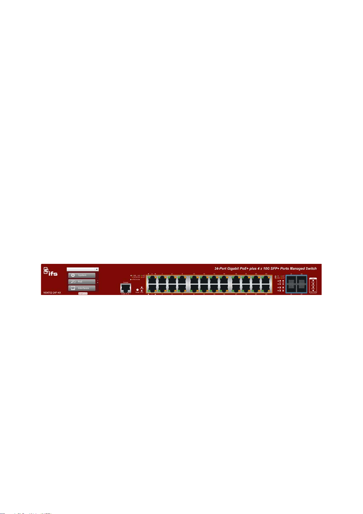
This section describes the hardware features and installation of the managed swit ch on
the desktop or rack mount. For easier management and control of the managed switch,
familiarize yourself with its display indicators, and ports. Front panel illustrations in this
chapter display the unit LED indicators. Before connecting any network device to the
managed switch, please read this chapter completely.
Hardware description
Switch front panel
Gigabit TP interface
10/100/1000BASE-T copper, RJ45 twisted-pair: Up to 100 meters.
10 gigabit SFP slots
10BASE-SR/LR mini-GBIC slot, SFP (Small Factor Pluggable) transceiver module
supports from 300 meters (multi-mode fiber) up to 10 kilometers (single-mode fiber).
Console port
The console port is a RJ45 port connector and an interface for directly connecting a
terminal. Through the console port, the managed switch provides diagnostic infor mation
including the IP address setting, factory reset, port management, link status, and
system setting. The included DB9 to RJ45 console cable connects to the console port
on the device. After making the connection, users can run any terminal emulation
program (Hyper Terminal, ProComm Plus, Telix, Winterm, and so on) to enter the
startup screen of the device
20 NS4702-24P-4X Managed Switch User Manual
Page 23

Chapter 2: Installation
Reset button presse
< 5 seconds: S
> 5 seconds: F
LED
P
SYS
FAN 1
FAN 2
FAN 3
PoE PWR
Reset button
Located on the right of the front panel, the reset button is designed to reboot the
managed switch without turning the power off and on. The following is the summary
table of the reset button functions:
d and released Function
ystem reboot Reboots the managed switch
actory default Resets the managed switch to factory default
configuration. The managed switch then
reboots and loads the default settings as
shown below:
Default Username: admin
Default Password: admin
Default IP address: 192.168.0.100
Subnet mask: 255.255.255.0
Default Gateway: 192.168.0.254
LED indicators
The front panel LEDs indicate port link status, data activity, and system power.
System/alert
Color Function
WR Green Lit: indicates that the managed switch has power.
Green
Red Lit: indicates that FAN1 is down.
Red Lit: indicates that FAN2 is down.
Red Lit: indicates that FAN3 is down.
Red Lit: indicates that the PoE power is down.
Lit: indicates that the firmware upgrade is complete.
Blinking: indicates that a firmware upgrade is in progress.
10/100/1000BASE-T interfaces (port 1 to port 24)
LED Color Function
Green Lit: indicates the port has successfully connected to the
network at 1000 Mbps.
Blinking: indicates that the switch is actively sending or
Ethernet
Orange Lit: indicates the port has successfully connected to the
PoE Orange Lit: indicates the port is providing DC in-line power.
receiving data over that port.
network at 100 Mbps or 10 Mbps.
Blinking: indicates that the switch is actively sending or
receiving data over that port.
Off: indicates that the connected device is not a P oE
Powered Device (PD)..
NS4702-24P-4X Managed Switch User Manual 21
Page 24

Chapter 2: Installation
1/10BASE-SR/LR SFP+ interfaces (port 25 to port 28)
LED Color Function
10G Orange Lit: indicates the port has successfully connected to the
network at 10 Gbps.
Blinking: indicates that the switch is actively sending or
receiving data over that port.
1000 Green Lit: indicates the port has successfully connected to the
network at 1000 Mbps.
Blinking: indicates that the switch is actively sending or
receiving data over that port.
Switch rear panel
The rear panel of the managed switch contains an AC inlet power socket that accepts
input power from 100 to 240 VAC, 50-60 Hz.
AC power receptacle
For compatibility with electrical supplies in most areas of the world, the managed
switch’s power supply automatically adjusts to line power in the range of 100-240 VAC
and 50/60 Hz.
Plug the female end of the power cord firmly into the receptacle on the rear panel of the
managed switch and the other end of the power cord into an electrical outlet and then
power it on.
Note: The device is a power-required device, meaning it will not work until it is powered
on. If your network needs to be active at all times, consider using a UPS (Uninterrupted
Power Supply) for the device to help to prevent network data loss or networ k downtime.
In some areas, installing a surge suppression device may also help to protect the
managed switch from an unregulated surge or current to the switch or the power
adapter.
Installing the switch
This section describes how to install and make connections to the managed switch.
Read the following topics and perform the procedures in the order presented.
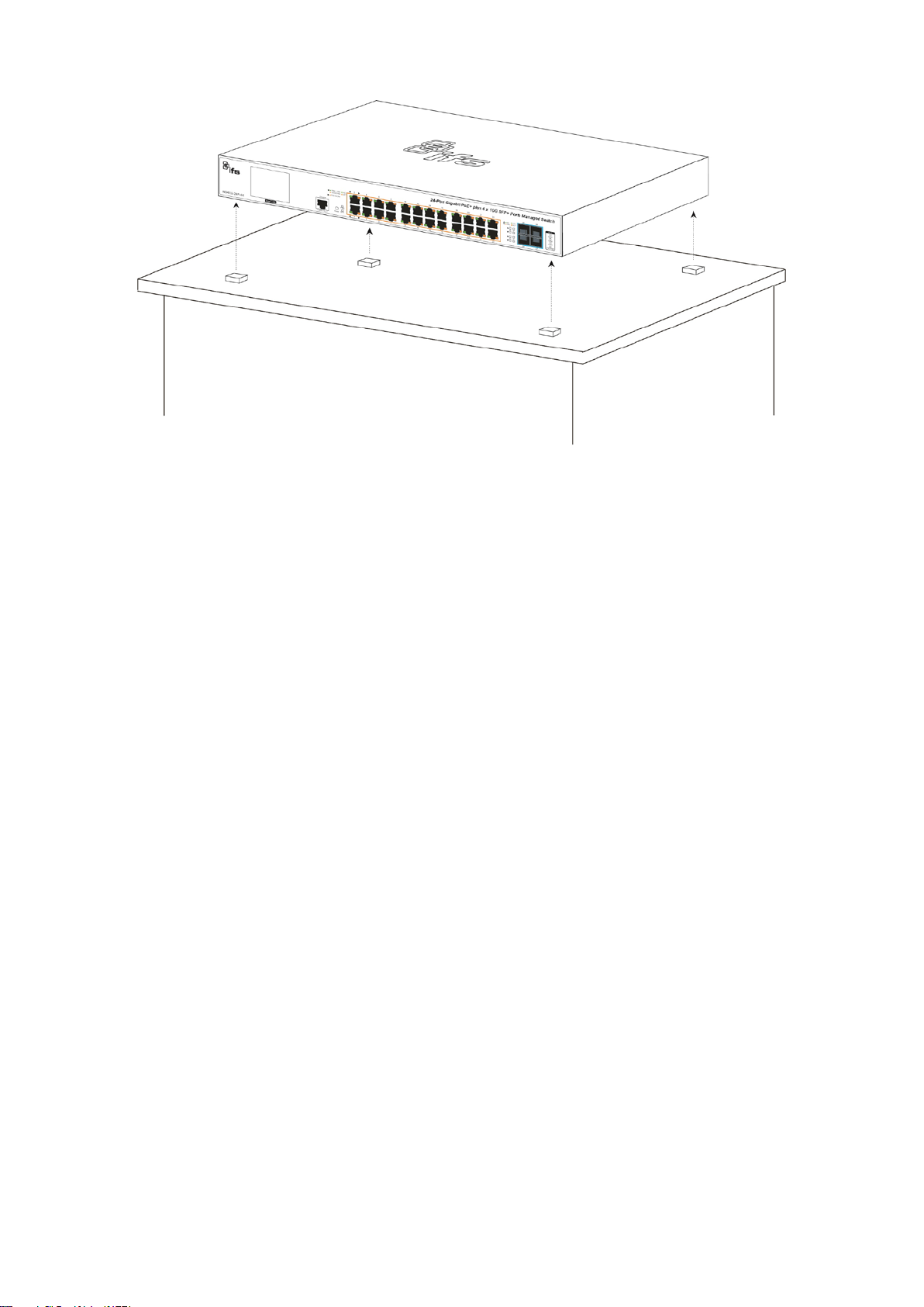
To install the managed switch on a desktop or shelf:
1. Attach the rubber feet to the recessed areas on the bottom of the managed switch.
2. Place the managed switch on the desktop or the shelf near an AC power source, as
shown below:
22 NS4702-24P-4X Managed Switch User Manual
Page 25
Chapter 2: Installation
3. Keep enough ventilation space between the managed switch and the surrounding
objects.
Note: When choosing a location, please keep in mind the environmental restrictions
indicated in “Product specifications” on page 17.
4. Connect one end of a standard network cable to the 10/100/1000 RJ45 ports on the
front of the managed switch and the other end of the cable to the network devices
such as printer servers, workstations or routers.
Note: Connection to the managed switch requires UTP Category 5 network cabling
with RJ45 tips. For more information, see Appendix A “Networking connection” on
page 331.
5. Connect one end of the power cable to the managed switch.
6. Connect the power plug of the power cable to a standard wall outlet.
7. When the managed switch receives power, the power LED illuminates solid green.
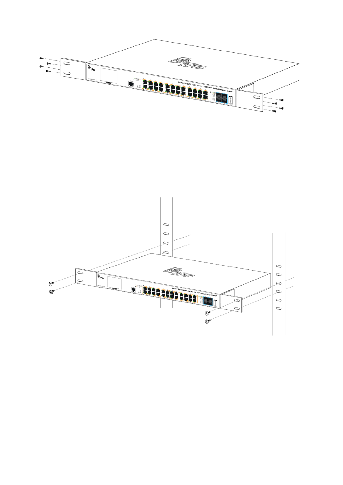
Rack mounting
To install the managed switch in a 19-inch standard rack:
1. Place the managed switch on a hard, flat surface with the front panel positioned
towards the front side.
2. Attach the rack-mount bracket to each side of the managed switch with the supplied
screws as shown below.
NS4702-24P-4X Managed Switch User Manual 23
Page 26
Chapter 2: Installation
Caution: You must use the screws supplied with the mounting brackets. Damage
caused to the parts by using incorrect screws will invalidate the warranty.
3. Secure the brackets tightly.
4. Follow the same steps to attach the second bracket to the opposite side.
5. After the brackets are attached to the managed switch, use suitable screws to
securely attach the brackets to the rack, as shown below.
6. Follow steps 4 through 7 under “To install the managed switch on a desktop or
shelf” in this section to connect the network cabling and supply power to the
managed switch.
Installing the SFP/SFP+ transceiver
SFP/SFP+ transceivers are hot-pluggable and hot-swappable. They can be plugged in
and removed to/from any SFP/SFP+ port without having to power down the managed
switch (see below).
24 NS4702-24P-4X Managed Switch User Manual
Page 27
Chapter 2: Installation
Approved Interlogix SFP transceivers
The managed switch supports both single mode and multi-mode SFP transceiver s. The
following list of approved Interlogix SFP transceivers is valid as of the time of
publication:
Part #
Fiber
Connector
# of
Fibers
Fiber
Type
Max
Distance
Wave
Length
Optical
Budget
(dBm)
Optical
Power
(dBm)
Receiver
Sensitivity
(dBm)
Operating
Temperature
Twisted Pair SFP 1000Base TX
S30-RJ RJ 45 1 Cat5e
Fast Ethernet 100Base FX
S20-2MLC2 LC 2
S25-2MLC2 LC 2
Fast Ethernet 100Base LX
S20-2SLC20 LC 2
S25-2SLC20 LC 2
Fast Ethernet 100Base BX
S20-1SLC/A20
LC 1
Multimode
Multimode
Single
Mode
Single
Mode
Single
Mode
100M
(328 ft.)
2 km
(1.2 mi.)
2 km
(1.2 mi.)
20 km
(12 mi.)
20 km
(12 mi.)
20 km
(12 mi.)
1310 nm 12 -20 ~ -14 -32
1310 nm 12 -20 ~ -14 -32
1310 nm 19 -15 ~ -8 -34
1310 nm 19 -15 ~ -8 -34
1310 /
1550 nm
18 -14 ~ -8 -32
0 to +50°C
(32 to 122°F)
0 to +50°C
(32 to 122°F)
-40 to +75°C
(-40 to
167°F)
0 to +50°C
(32 to 122°F)
-40 to +75°C
(-40 to 167°F)
0 to +50°C
(32 to 122°F)
S25-1SLC/B20
Gigabit Ethernet 1000Base SX
NS4702-24P-4X Managed Switch User Manual 25
LC 1
Single
Mode
20 km
(12 mi.)
1550 /
1310 nm
18 -14 ~ -8 -32
-40 to +75°C
(-40 to 167°F)
Page 28

Chapter 2: Installation
Part #
S30-2MLC LC 2
S35-2MLC LC 2
OM1 Multimode fiber @ 200/500 MHz-km
OM2 Multimode fiber @ 500.500 MHZ-km Laser Rated for GbE LANs
S30-2MLC-2 LC 2
OM3 Multimode fiber @ 2000/500MHz-km Optimized got 850 nm VCSELs
Gigabit Ethernet 1000 Base LX
S30-2SLC10
S35-2SLC10
Fiber
Connector
LC 2
LC 2
# of
Fibers
Fiber
Type
Multimode
Multimode
Multimode
Single
Mode
Single
Mode
Max
Distance
220/550 m
(720 /
1800 ft.)
220/550 m
(720 /
1800 ft.)
2 km
(1.2 mi.)
10 km
(6.2 mi.)
10 km
(6.2 mi.)
Wave
Length
850 nm 7.5 -9.5 ~ -1 -17
850 nm 7.5 -14 ~ -8 -17
1310 nm 10 -9 ~ -1 -19
1310 nm 18 -9.5 ~ -3 -20
1310 nm 18 -9.5 ~ -3 -20
Optical
Budget
(dBm)
Optical
Power
(dBm)
Receiver
Sensitivity
(dBm)
Operating
Temperature
0 to +50°C
(32 to 122°F
-40 to +75°C
(-40 to 167°F)
0 to +50°C
(32 to 122°F)
0 to +50°C
(32 to 122°F)
-40 to +75°C
(-40 to 167°F)
S30-2SLC30
S35-2SLC30
Gigabit Ethernet 1000 Base ZX
S30-2SLC70
S35-2SLC70
Gigabit Ethernet 1000 Base BX
S30-1SLC/A10
S30-1SLC/B10
S30-1SLC/A20
LC 2
LC 2
LC 2
LC 2
LC 1
LC 1
LC 1
Single
Mode
Single
Mode
Single
Mode
Single
Mode
Single
Mode
Single
Mode
Single
Mode
30 km
(18.6 mi.)
30 km
(18.6 mi.)
70 km
(43 mi.)
70 km
(43 mi.)
10 km
(6.2 mi.)
10 km
(6.2 mi.)
20 km
(12 mi.)
1310 nm 18 -2 ~ +3 -23
1310 nm 18 -2 ~ +3 -23
1550 nm 19* -15 ~ -8 -34
1550 nm 19* -15 ~ -8 -34
1310 /
1490 nm
1490 /
1310 nm
1310 /
1490 nm
11 -9 ~ -3 -20
11 -9 ~ -3 -20
15 -8 ~ -2 -23
0 to +50°C
(32 to 122°F)
-40 to +75°C
(-40 to 167°F)
0 to +50°C
(32 to 122°F)
-40 to +75°C
(-40 to 167°F)
0 to +50°C
(32 to 122°F)
0 to +50°C
(32 to 122°F)
0 to +50°C
(32 to 122°F)
S30-1SLC/B20
Gigabit Ethernet 1000 Base BX
S30-1SLC/A60
26 NS4702-24P-4X Managed Switch User Manual
LC 1
LC 1
Single
Mode
Single
Mode
20 km
(12 mi.)
60 km
(37 mi.)
1490 /
1310 nm
1310 /
1490 nm
15 -8 ~ -2 -23
24 0 ~ +5 -24
0 to +50°C
(32 to 122°F)
0 to +50°C
(32 to 122°F)
Page 29

Chapter 2: Installation
Part #
S30-1SLC/B60
10GBase-SR SFP+
S40-2MLC LC 2
*OM3 Multimode fiber @ 2000/500MHz-km Optimized got 850 nm VCSELs maximum distance of 300m.
10GBase-LR SFP+
S40-2SLC10
* Note: High Power Optic. There must be a minimum of 5 dB of optical loss to the fiber for proper operation.
Fiber
Connector
LC 1
LC 2
# of
Fibers
Fiber
Type
Single
Mode
Multimode
Single
Mode
Max
Distance
60 km
(37 mi.)
300 m* 850 nm 10 -7.3 ~ -1 -11
10 km
(6.2 mi.)
Wave
Length
1490 /
1310 nm
1310 nm 15
Optical
Budget
(dBm)
24 0 ~ +5 -24
Optical
Power
(dBm)
-8.2 ~
+0.5
Receiver
Sensitivity
(dBm)
-12
Note: We recommend the use of Interlogix SFPs on the managed switch. I f you inser t
an SFP transceiver that is not supported, the managed switch will not recognize it .
Note: Ports 25 to 28 are a shared SFP+ slot that supports the 10 gigabit SFP+
transceiver and gigabit SFP transceiver.
Operating
Temperature
0 to +50°C
(32 to 122°F)
0 to +50°C
(32 to 122°F)
0 to +50°C
(32 to 122°F)
Before connecting the other managed switches, workstation, or media converter:
1. Make sure both sides of the SFP transceiver are with the same media type. For
example, 1000BASE-SX to 1000BASE-SX, 1000BASE-LX t o 1000BAS E-LX.
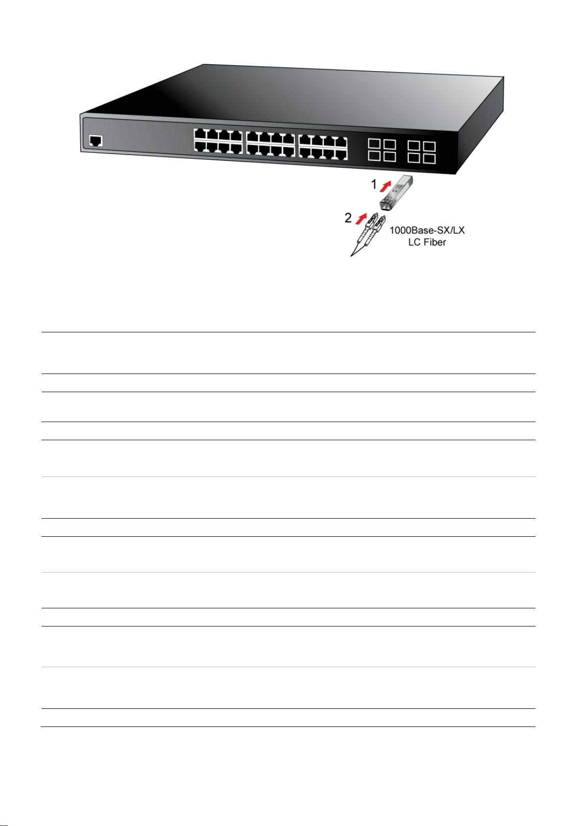
2. Check if the fiber-optic cable type matches the SFP transceiver model.
• To connect to 1000BASE-SX SFP transceiver, use the multi-mode fiber cable –
with one side being male duplex LC connector type.
• To connect to 1000BASE-LX SFP transceiver, use the single-mode fiber cable –
with one side being male duplex LC connector type.
To connect the fiber cable:
1. Attach the duplex LC connector on the network cable to the SFP/SFP+ transceiver.
2. Connect the other end of the cable to a device with the SFP/SFP+ transceiver
installed.
3. Check the LNK/ACT LED of the SFP/SFP+ slot on the front of the managed switch.
Ensure that the SFP/SFP+ transceiver is operating correctly.
4. Check the link mode of the SFP/SFP+ port if the link fails. Set the link mode to
“1000 Force” or “10G Force” so that it can work with certain fiber-NICs or media
converters if required. The default setting is 10G forced mode.
NS4702-24P-4X Managed Switch User Manual 27
Page 30
Chapter 2: Installation
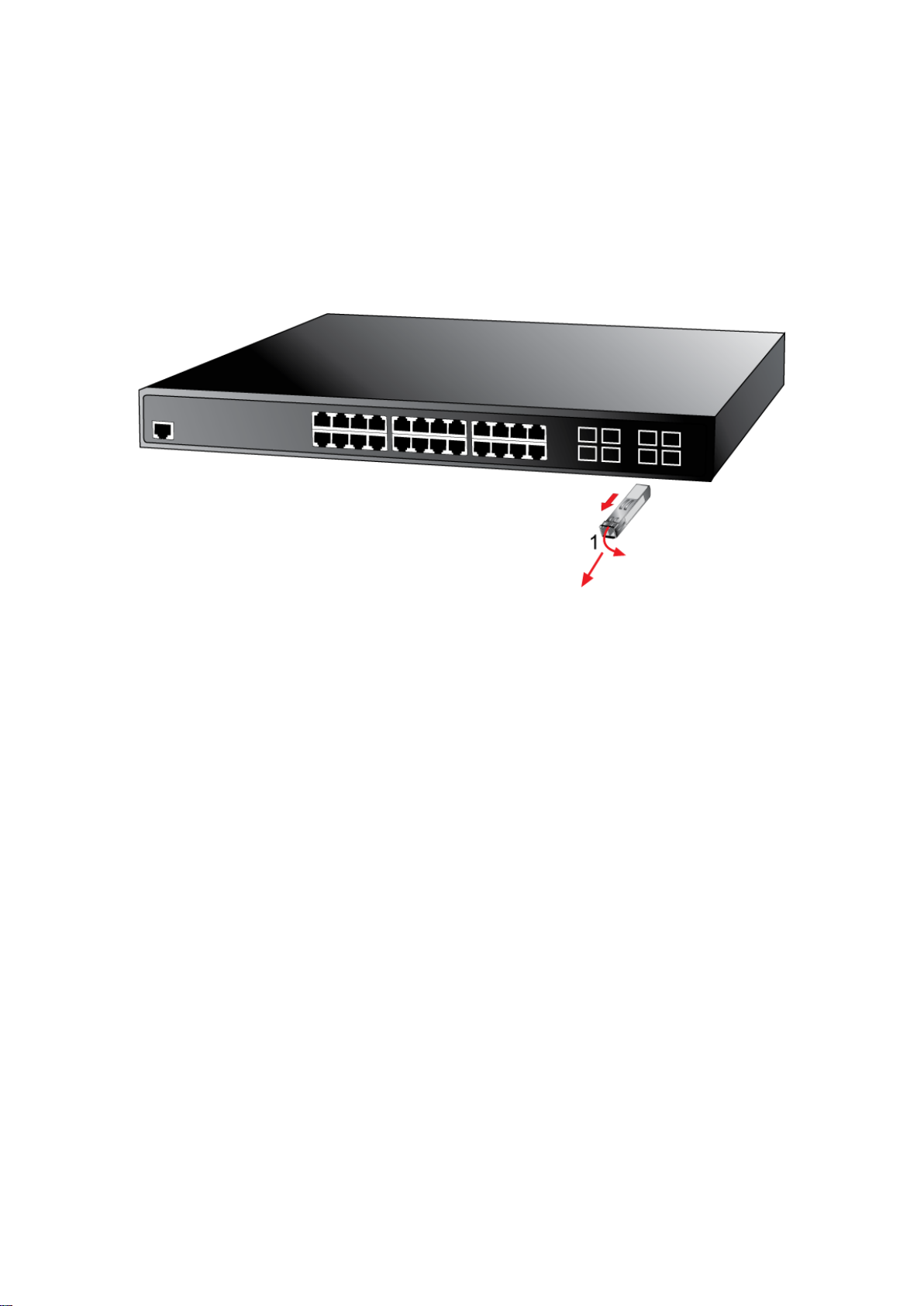
To remove the transceiver module:
1. Make sure there is no network activity by checking with the network administrator.
Or, through the management interface of the switch/converter (if available), disable
the port in advance.
2. Carefully remove the fiber optic cable.
3. Turn the lever of the transceiver module to a horizontal position.
4. Pull out the module gently through the lever.
Note: Never pull out the module without making use of the lever or the push bolts on
the module. Removing the module with force could damage the module and the
SFP/SFP+ module slot of the managed switch.
28 NS4702-24P-4X Managed Switch User Manual
Page 31

Chapter 3
Switch management
This chapter explains the methods that can be used to configure management acc ess
to the managed switch. It describes the types of management applications and the
communication and management protocols that deliver data between the management
device (workstation or personal computer) and the system. It also contains information
about port connection options.
Requirements
• Workstations must have Windows XP or later, Mac OS9 or later, Linux, UNIX , or
other platforms compatible with TCP/IP protocols.
• Workstations must have an Ethernet NIC (Network Interface Card) installed.
• Serial Port connection (Terminal). The workstation must have a COM Port (DB9 /
RS-232) or USB-to-RS-232 converter.
• Ethernet port connection. Use standard network (UTP) cables with RJ45
connectors.
• Workstations must have a web browser and Java runtime environment plug-in
installed.
Note: We recommend the use of Internet Explorer 11.0 or later to access the managed
switch.
Management access overview
The managed switch provides the flexibility to access and manage it using any or all of
the following methods:
• An administration console
• Web browser interface
• An external SNMP-based network management application
NS4702-24P-4X Managed Switch User Manual 29
Page 32

Chapter 3: Switch management
Method
Console
• Secure
W
• Most visually appealing.
SNMP agent
name).
The administration console and web browser interface support are embedded in the
managed switch software and are available for immediate use. The advantages of
these management methods are described below:
Advantages Disadvantages
eb browser
• No IP address or subnet needed.
• Text-based
• Telnet functionality and
HyperTerminal built into Windows
operating systems.
• Ideal for configuring the switch
remotely.
• Compatible with all popular
browsers.
• Can be accessed from any
location.
• Communicates with switch
functions at the MIB level.
• Based on open standards.
• Must be near the switch or use dial-up
connection.
• Not convenient for remote users.
• Modem connection may prove to be
unreliable or slow.
• Security can be compromised (hackers
need only know the IP address and
subnet mask).
• May encounter lag times on poor
connections.
• Requires SNMP manager software
• Least visually appealing of all three
methods.
• Some settings require calculations.
• Security can be compromised (hackers
need to only know the community
Administration console
The administration console is an internal, character-oriented, and comm and li ne us er
interface for performing system administration such as displaying statistics or changing
option settings. Using this method, you can view the administration console from a
terminal, a computer, or workstation connected to the managed switch's console
(serial) port.
30 NS4702-24P-4X Managed Switch User Manual
Page 33

Chapter 3: Switch management
Direct access
Direct access to the administration console is achieved by directly connecting a
terminal or a computer equipped with a terminal-emulation program ( s uch as
HyperTerminal) to the managed switch console (serial) port. When using this
management method, a straight DB9 RS-232 cable is required to connect the switch to
the computer. After making this connection, configure the terminal-emulation program
to use the following parameters:
These settings can be changed after log on, if required. This management method is
often preferred because the user can remain connected and monitor the system during
system reboots. Also, certain error messages are sent to the serial port, regardless of
the interface through which the associated action was initiated. A computer attachment
can use any terminal emulation program for connecting to the terminal serial port. A
workstation attachment under UNIX can use an emulator such as TIP.
NS4702-24P-4X Managed Switch User Manual 31
Page 34

Chapter 3: Switch management
Web management
The managed switch provides features that allow users to manage it from anywhere on
the network through a standard browser such as Microsoft Internet Explorer. After
setting up the IP address for the switch, you can access the managed switch's web
interface applications directly in the web browser by entering the IP addres s of t he
managed switch.
You can use a web browser to list and manage the managed switch configuration
parameters from one central location, just as if you were directly connected to the
managed switch's console port. Web management requires Microsoft Inter net Explorer
11.0 or later.
SNMP-based network managem ent
Use an external SNMP-based application to configure and manage the managed
switch, such as SNMP Network Manager, HP Openview Network Node Management
(NNM), or What’s Up Gold. This management method requires the SNMP agent on the
switch and the SNMP Network Management Station to use the same community string.
This management method uses two community strings: the get community string and
the set community string. If the SNMP Network Management Station only knows the set
community string, it can read and write to the MIBs. However, if it only knows the get
community string, it can only read MIBs. The default get and set community strings for
the managed switch are public.
32 NS4702-24P-4X Managed Switch User Manual
Page 35

Chapter 3: Switch management
Smart discovery utility
For easily listing the managed switch in your Ethernet environment, the Smart
Discovery utility included on the CD-ROM is an ideal solution.
To run the smart discovery utility:
1. Install the Smart Discovery Utility in the administrator PC.
2. Run the utility.
Note: If there are two or more LAN cards in the same administrator computer,
choose a different LAN card by using the “Select Adapter” tool.
3. Click the Refresh button for the currently connected devices in the discovery list :
4. This utility shows all necessary information from the devices, such as MAC address,
device name, firmware version and device IP subnet address. It can also assign
new password, IP Subnet address and description for the devices. After setup is
complete, click the Update Device, Update Multi, or Update All button:
• Update Device: Use the current setting on one single device.
• Update Multi: Use the current setting on multi-devices.
• Update All: Use the current setting on all devices in the list.
The same functions mentioned above also can be found in Option menu.
5. Selecting the Control Packet Force Broadcast check box allows you to assign a
new setting value to the Web Smart Switch under a different IP subnet address.
6. Click the Connect to Device button and the web login screen appears.
7. Click the Exit button to shut down the Smart Discovery Utility.
NS4702-24P-4X Managed Switch User Manual 33
Page 36

Chapter 4
Web configuration
This section introduces the configuration and functions of the web-based managem ent
interface for the managed switch.
About Web-based management
Web-based management of the managed switch supports Internet Explorer 7.0 or later,
and can be performed from any location on the network. It is based on Java Applets
with an aim to reduce network bandwidth consumption, enhance access speed, and
present an easy viewing screen.
Note: By default, IE 11.0 and above does not allow Java Applets to open sockets. The
user has to explicitly modify the browser setting to enable Java Applets to use network
ports.
The managed switch can be configured through an Ethernet connection when the
manager computer is set to the same IP subnet address as the managed switch.
For example, if the default IP address of the managed switch is 192.168.0.100, then the
administrator computer should be set at 192.168.0.x (where x is a number between 1
and 254, except 100), and the default subnet mask is 255.255.255.0.
If the default IP address of the managed switch has been changed to 192.168.1. 1 with
subnet mask 255.255.255.0 via the console, then the administrator computer should be
set at 192.168.1.x (where x is a number between 2 and 254) to do the relative
configuration on a manager computer.
NS4702-24P-4X Managed Switch User Manual 34
Page 37

Chapter 4: Web configuration
1. Main menu
2.
3. SFP/SFP+ port link status
4. Help
5.
To log into the managed switch:
1. Launch the Internet Explorer 7.0 or later web browser and type the factory default IP
address http://192.168.0.100 to access the web interface.
2. When the following login screen appears, type the default usernam e "admin" with
password “admin” (or the username and password you have changed via console)
to log into the main screen of the managed switch.
3. After typing the username and password, the main UI screen appears. The main
menu on the left side of the web page permits access to all the functions and status
provided by the managed switch.
Note: For security purposes, change and memorize the new password after this first
setup.
Main web page
This section describes how to use the managed switch’s web browser interface for
configuration and management.
Copper port link status
NS4702-24P-4X Managed Switch User Manual 35
Main screen
Page 38

Chapter 4: Web configuration
Panel display
The web interface displays an image of the managed switch’s ports. The mode can be
set to display different information for the ports, including Link up or Link down. Clicking
on the image of a port opens the Port Statistics page.
Port status is indicated as follows:
State Disabled Down Link
RJ45 Ports
SFP Ports
Main menu
Using the web interface, you can define system parameters, manage, and control the
managed switch and all its ports, or monitor network conditions. The administ r ator can
set up the managed switch by making selections from the main functions menu.
Clicking on a main menu item opens sub menus.
System
Use the System menu items to display and configure basic administrative details of the
managed switch. Under the System list, the following topics are provided t o c onf igur e
and view the system information. This list contains the followin g items:
36 NS4702-24P-4X Managed Switch User Manual
Page 39

Chapter 4: Web configuration
Item Function
System Information The managed switch system information is provided here.
IP Configuration Configures the managed switch-managed IPv4/IPv6 interface and IP routes
on this page.
IP Status This page displays the status of the IP protocol lay er. The status is defined
by the IP interfaces, the IP routes and the neighbou r cache (ARP cache)
status.
Users Configuration This page provides an overview of the current users. Currently the only way
to log in as another user on the web server is to close and reo pen the
browser.
Privilege Levels This page provides an overview of the privilege levels.
NTP Configuration Configure NTP server on this page.
Time Configuration Configure time parameter on this page.
UPnP Configure UPnP on this page.
DHCP Relay Configure DHCP Relay on this page.
DHCP Relay Statistics This page provides statistics for DHCP relay.
CPU Load This page displays the CPU load using an SVG graph.
System Log The managed switch system log information is provi ded here.
Detailed Log The managed switch system detailed log information is provided here.
Remote Syslog Configure remote syslog on this page.
SMTP Configuration Configure SMTP parameters on thi s page.
Web Firmware
Upgrade
TFTP Firmware
Upgrade
Save Startup Config This copies running-config to startup-config, thereby ensuring that the
Configuration
Download
Configuration Upload Upload files to the switch.
Configuration
Activate
Configuration Delete Delete the writable files stored in flash.
Image Select Configure active or alternate firmware on this page.
This page facilitates an update of the firmware controlling the managed
switch.
Upgrade the firmware via TFTP server
currently active configuration will be used at the next reboot.
Download the files to the switch.
Activate the configuration file present on the swit ch.
System Reboot You can restart the managed switch on this page. After restarting, the
managed switch will boot normally.
System information
The System Infomation page provides information on the current device such as the
hardware MAC address, software version, and system uptime.
NS4702-24P-4X Managed Switch User Manual 37
Page 40

Chapter 4: Web configuration
The page includes the following fields:
Item Function
Contact The system contact configured in SNMP > System Information.
Name The system name configured in SNMP > System Information.
Location The system location configured in SNMP > System Information.
MAC Address The MAC Address of this managed switch.
Power Status Indicated the type of power applied to the managed switch.
Temperature Indicates chipset temperature.
System Date The current (GMT) system time and date. The system time is obtained throug h the
configured NTP server, if present.
System Uptime The period of time the device has been operational.
Software Version The software version of the managed switch.
Software Date The date when the managed switch software was produced.
• Select the Auto-refresh check box to refresh the page automatically. Automatic
refresh occurs every three seconds.
• Click Refresh to refresh the page automatically. This will undo any changes m ade
locally.
IP configuration
This page includes the IP Configuration, IP Interface, and IP Routes. The configured
column is used to view or change the IP configuration. The maximum number of
interfaces supported is 128 and the maximum number of routes is 32.
38 NS4702-24P-4X Managed Switch User Manual
Page 41

Chapter 4: Web configuration
unicast (except linklocal) address of the DNS Server.
The current column is used to show the active IP configuration.
Object Description
IP
Configurations
Mode
Domain Name
Set the IP stack to act as a Host or a Router. In Host
mode, IP traffic between interfaces will not be rout ed. In
Router mode traffic is routed between all i nterfaces.
The name string of local domain where the device
belongs. Most queries for names within this domain c an
use short names relative to the local domain. The
system then appends the domain name as a suffix to
unqualified names.
For example, if the domain name is set as
'example.com' and you specify the PING destination by
the unqualified name as 'test', then the system will
qualify the name to be 'test.example.com'.
The following modes are supported:
No Domain Name – No domain name will be used.
Configured Domain Name – Explicitly specify the name
of local domain. Make sure the configured domain name
meets your organization's given domain.
From any DHCPv6 interfaces – The first domain name
offered from a DHCPv6 lease to a DHCPv6-enabled
interface will be used.
From this DHCPv6 interface – Specify from which
DHCPv6-enabled interface a provided domain nam e
should be preferred.
DNS Server
NS4702-24P-4X Managed Switch User Manual 39
This setting controls the DNS name resolution done by
the switch. There are four servers available for
configuration, and the index of the server present s t he
preference (less index has higher priority) in doing DNS
name resolution. The following modes are supported:
No DNS server – No DNS server will be used.
Configured IPv4 – Explicitly provide the valid IP v4
unicast address of the DNS Server in dotted decimal
notation. Make sure the configured DNS server is
reachable (e.g., via PING) for activating DNS service.
Configured IPv6 – Explicitly provide the valid IP v6
Page 42

Chapter 4: Web configuration
Make sure the configured DNS server is reachable (e.g. ,
this option is enabled, the system configures the IPv6
Object Description
via PING6) for activating DNS service.
From any DHCPv4 interfaces – The first DNS server
offered from a DHCPv4 lease to a DHCPv4-enabled
interface will be used.
From this DHCPv4 interface – Specify from which
DHCPv4-enabled interface a provided DNS se rver
should be preferred.
From any DHCPv6 interfaces – The first DNS server
offered from a DHCPv6 lease to a DHCPv6-enabled
interface will be used.
From this DHCPv6 interface – Specify from which
DHCPv6-enabled interface a provided DNS se rv er
should be preferred.
IP Address
DNS Proxy
Delete
VLAN
DHCPv4 Enabled
Fallback
Current
Lease
When DNS proxy is enabled, the system will relay DNS
requests to the currently configured DNS server, and
reply as a DNS resolver to the client devices on the
network.
Select this option to delete an existing IP interface.
The VLAN associated with the IP interface. Only ports in
this VLAN will be able to access the IP interface. This
field is only available for input when creating an new
interface.
Enable the DHCP client by selecting this check box. If
this option is enabled, the system will configure the I Pv4
address and mask of the interface using the DHCPv4
protocol. The DHCPv4 client will announce the
configured System Name as hostname to provide DN S
lookup
The number of seconds for trying to obtain a DHCP
lease. If this option is enabled, the system will conf i gure
the IPv4 address and mask of the interface using the
DHCPv4 protocol. The DHCPv4 client will announce t he
configured System Name as hostname to provide DNS
lookup.
For DHCP interfaces with an active lease, this column
shows the current interface address, as provided by the
DHCP server.
IPv4 Address
DHCPv6
40 NS4702-24P-4X Managed Switch User Manual
Mask Length
Enable Enable the DHCPv6 client by selecting this check box. If
Provides the IP address of this managed switch in
dotted decimal notation. If DHCP is enabled, this field
configures the fallback address. The field may be left
blank if IPv4 operation on the interface is not required, or
if no DHCP fallback address is required
The IPv4 network mask, in number of bits (prefix length).
Valid values are between 0 and 30 bits for a IPv4
address. If DHCP is enabled, this field configures t he
fallback address network mask. The field may be lef t
blank if IPv4 operation on the interface is not required, or
if no DHCP fallback address is required.
Page 43

Chapter 4: Web configuration
address of the interface using the DHCPv6 protocol.
Object Description
Rapid
Commit
Current
Lease
IPv6 Address
Mask Length
Enable the DHCPv6 Rapid-Commit option by selectin g
this check box. If this option is enabled, the DHCPv6
client terminates the waiting process as soon as a Reply
message with a Rapid Commit option is received. Thi s
option is only manageable when the DHCPv6 client is
enabled.
For DHCPv6 interface with an active lease, this column
shows the interface address provided by the DHCP v6
server.
Provides the IP address of this managed switch. A IPv6
address is in 128-bit records represented as eight f i el ds
of up to four hexadecimal digits with a colon separating
each field (:).For example, fe80::215:c5ff:fe03:4dc7. The
symbol :: is a special syntax that can be used as a
shorthand way of representing multiple 16-bit groups of
contiguous zeros; but it can appear only once.
The system accepts the valid IPv6 unicast address only,
except the IPv4-Compatible address and IPv4-Mapped
address. The field may be left blank if IPv6 operatio n on
the interface is not required.
The IPv6 network mask, in number of bits (prefix length).
Valid values are between 1 and 128 bits for a IPv6
address.
The field may be left blank if IPv6 operation on the
interface is not required.
IP Routes
Delete
Network
Mask Length
Gateway
Next Hop VLAN
Select this option to delete an existing IP route.
The destination IP network or host address of this ro ute.
Valid format is dotted decimal notationor a valid IPv6
notation. A default route can use the value 0.0.0.0 or
IPv6 :: notation.
The destination IP network or host mask, in number of
bits (prefix length). It defines how much of a network
address that must match in order to qualify for this rout e.
Valid values are between 0 and 32 bits respectively 128
for IPv6 routes. Only a default route will have a mask
length of 0 as it will match anything.
The IP address of the IP gateway. Valid format is dotted
decimal notation or a valid IPv6 notation. Gateway and
Network must be of the same type.
The VLAN ID (VID) of the specific IPv6 interface
associated with the gateway. The given VI D rang es from
1 to 4095 and will be effective only when the
corresponding IPv6 interface is valid.
If the IPv6 gateway address is link-local, it must specify
the next hop VLAN for the gateway. If the IPv6 gateway
address is not link-local, the system ignores the next hop
VLAN for the gateway.
NS4702-24P-4X Managed Switch User Manual 41
Page 44

Chapter 4: Web configuration
Buttons
• Click Add Interface to add a new IP interface. A maximum of 128 interfaces is
supported.
• Click Add Route to add a new IP route. A maximum of 32 routes is supported.
• Click Apply to apply changes.
• Click Reset to undo any changes made locally and revert to previously saved
values.
IP status
IP status displays the status of the IP protocol layer. The status is defined by the IP
interfaces, the IP routes, and the neighbour cache (ARP cache) status.
42 NS4702-24P-4X Managed Switch User Manual
Page 45

Chapter 4: Web configuration
By default, most groups’ privilege level 5 has read-onl y access and privilege level
The page includes the following fields:
Object Description
IP Interfaces Interface The name of the interface.
Type
Address The current address of the interface (of the given ty pe).
Status The status flags of the interface (and/or address ).
IP Routes
Neighbor Cache IP Address The IP address of the entry.
Network
Gateway The gateway address of this route.
Status The status flags of the route.
Link Address
The address type of the entry. This may be LINK or
IPv4.
The destination IP network or host address of thi s
route.
The link (MAC) address for which a binding to the IP
address given exists.
• Select the Auto-refresh check box to refresh the page automatically. Automatic
refresh occurs every three seconds.
• Click Refresh to refresh the page automatically. This will undo any changes m ade
locally.
Users configuration
This page provides an overview of the current users. Close and reopen the browser to
log in as another user on the web server. After setup is complete, click the Apply
button and log in to the web interface with the new user name and password. The
following appears:
This page includes the following fields:
Object Description
User Name The name identifying the user. This is also a link to Add/Edit User.
Privilege Level The privilege level of the user.
The allowed range is 1 to 15. If the privilege level valu e i s 15, i t can access all
groups (i.e., it is granted full control of the device). Other values need to refer to
each group privilege level. User privileges should be the same or great er than the
group privilege level to have access to that grou p.
NS4702-24P-4X Managed Switch User Manual 43
Page 46

Chapter 4: Web configuration
10 has read-write access. System maintenance (software upload, factory
Object Description
defaults, etc.) requires user privilege level 15.
Generally, privilege level 15 can be used for an admi nist rat or account, privilege
level 10 for a standard user account, and privilege lev el 5 for a guest account.
Buttons:
• Click Add New User to add a new user
Add/edit user
Add, edit, or delete a user in this page.
This page includes the following fields:
Object Description
User Name A string identifies the user name that this entry should bel ong to. The allowed
string length is 1 to 31. The valid user name is a combination of letters,
numbers, and underscores.
Password The password of the user. The allowed string length is 1 to 31.
Password (again) Type the user password agai n for confirmation.
Privilege Level The privilege level of the user.
The allowed range is 1 to 15. If the privilege level valu e is 15, it can access all
groups (i.e., it is granted full control of the device). But other values need to
refer to each group privilege level. User privileges should be the same or
greater than the group privilege level to have access to that group.
By default, most groups’ privilege level 5 has read-only access and privilege
level 10 has read-write access. System maintenance (software upload, factory
defaults, etc.) requires user privilege level 15.
Generally, privilege level 15 can be used for an admi nist rat or account,
privilege level 10 for a standard user account, and privilege level 5 for a guest
account.
Buttons
• Click Apply to apply changes.
• Click Reset to undo any changes made locally and revert to previously saved
values.
44 NS4702-24P-4X Managed Switch User Manual
Page 47

Chapter 4: Web configuration
• Click Cancel to undo changes and return to the Users Configuration page.
• Click Delete User to delete the current user. This function is not available for new
configurations (i.e., add new user).
After a new user is added, the new user entry appears in the Users Configuration page.
Note: If a password is forgotten after changing the default password, press the reset
button on the front panel of the managed switch for over 10 seconds and then release
it. The current settings, including VLAN, will be erased and the managed switch
restores to default mode.
Privilege levels
This page provides an overview of the privilege levels. After setup is complete, click the
Apply button and log in to the web interface with the new user name and password.
The following appears:
NS4702-24P-4X Managed Switch User Manual 45
Page 48

Chapter 4: Web configuration
This page includes the following fields:
Object Description
Group name The name identifies the privilege group. In most cases, a privilege level group
consists of a single module (e.g., LACP, RSTP, or QoS ), but a few of them
contain more than one. The following description d efines these privilege level
groups in detail:
System: Contact, Name, Location, Timezon e, Log.
Security: Authentication, System Access Management, P ort (contains Dot1x
port, MAC based and the MAC Address Limit), ACL, HTTPS, SSH, ARP
Inspection, and IP source guard.
IP: Everything except 'ping'.
Port: Everything except 'VeriPHY'.
Diagnostics: 'ping' and 'VeriPHY'.
Maintenance: CLI- System Reboot, System Restore Default, System
Password, Configuration Save, Configuration Load and Firmware Load. WebUsers, Privilege Levels and everything in Maintenance.
Debug: Only present in CLI.
Privilege Level Every privilege level group has an authorization level for the f ol l owing sub
groups:
Configuration read-only
Configuration/execute read-write
Status/statistics read-only
Status/statistics read-write (e.g., for clearing of statistics)
46 NS4702-24P-4X Managed Switch User Manual
Page 49

Chapter 4: Web configuration
contiguous zeros; but it can only appear once. It al so uses an IPv4 address
Buttons
• Click Apply to apply changes.
• Click Reset to undo any changes made locally and revert to previously saved
values.
NTP configuration
Configure NTP on this page. NTP is an acronym for Network Time Protocol, a network
protocol for synchronizing the clocks of computer systems. NTP uses UDP (data
grams) as a transport layer. You can specify NTP servers in this page.
This page includes the following fields:
Object Description
Mode Indicates the NTP mode operation. Possible modes are:
Enabled: Enable NTP mode operation. When enabling NTP mode operation,
the agent forwards and transfers NTP messages b etween the clients and the
server when they are not on the same subnet domain.
Disabled: Disable NTP mode operation.
Server# Provides the NTP IPv4 or IPv6 address of this switch. IPv6 address is in 128-
bit records represented as eight fields of up to four he xadecimal digits with a
colon separating each field (:).
Example: 'fe80::215:c5ff:fe03:4dc7'. The symbol '::' is a special syntax that
can be used as a shorthand way of representing multiple 16-bit groups of
NS4702-24P-4X Managed Switch User Manual 47
Page 50

Chapter 4: Web configuration
(for example, '::192.1.2.34').
Object Description
User Manually Allows the user to enable set up system time manually. System time will be
lost after system reboot since there is no battery to keep t i me running.
Year Allows the user to input year value. (it supports from 1970 to 20 37 only)
Month Allows the user to input month value. (1 to 12 month).
Day Allows the user to input day value. (1 to 31 days).
Hour Allows the user to input hour value. (00 to 23 hours).
Minute Allows the u ser to input minute value. (0 to 59 minutes).
Second Allows the us er to input second value. (0 to 59 seconds).
Buttons
• Click Apply to apply changes.
• Click Reset to undo any changes made locally and revert to previously saved
values.
Time configuration
A time zone is a region that has a uniform standard time for legal, commercial, and
social purposes. It is convenient for areas in close commercial or other communication
to maintain the same time, so time zones tend to follow the boundaries of countries and
their subdivisions. Configure the time zone on the Time Zone Configuration page.
48 NS4702-24P-4X Managed Switch User Manual
Page 51

Chapter 4: Web configuration
This page includes the following fields:
Object Description
Time Zone Lists various Time Zones worldwide. Select the appr opriat e Ti me Zone from
the drop-down list and click Save.
Acronym This is a user configurable acronym (up to 16 characters) used to identi fy the
time zone.
Daylight Saving
Time
Start Time Settings Week - Select the starting week number.
End Time Settings Week - Select the ending week number.
Offset Settings Enter the number of minutes (1 to 1440) to add during Daylight Savi ng T im e.
This is used to set the clock forward or backward acco rding to the
configurations set below for a defined Daylight Saving Time duration. Select
Disable to disable the Daylight Saving Time configurati on. S el ect Recurring
and configure the Daylight Saving Time duration to re peat the configuration
every year. Select Non-Recurring and configure the Daylight Sav ing Ti m e
duration for single time configuration. (Default: Disabled).
Day - Select the starting day.
Month - Select the starting month.
Hours - Select the starting hour.
Minutes - Select the starting minute.
Day - Select the ending day.
Month - Select the ending month.
Hours - Select the ending hour.
Minutes - Select the ending minute
Buttons
• Click Apply to apply changes.
• Click Reset to undo any changes made locally and revert to previously saved
values.
UPnP
UPnP is an acronym for Universal Plug and Play. The goals of UPnP are to allow
devices to connect seamlessly and to simplify the implementation of networks in home
(data sharing, communications, and entertainment) and corporate environments for
easy installation of computer components. Configure UPnP on the UPnP Configuration
page.
NS4702-24P-4X Managed Switch User Manual 49
Page 52

Chapter 4: Web configuration
This page includes the following fields:
Object Description
Mode Indicates the UPnP operation mode. Possible modes are:
Enabled: Enable UPnP mode operation.
Disabled: Disable UPnP mode operation.
When the mode is enabled, two ACEs are added automatically to trap UPnP
related packets to the CPU. The ACEs are automatical l y removed when the
mode is disabled.
Advertising
Duration
IP Address Mode IP addressing mode provides two ways to determine IP address assignment:
Static VLAN
Interface ID
The duration, carried in SSDP packets, is used to inform a control point or
control points how often it or they should receive a S SDP advertisement
message from this switch. If a control point doe s not rec ei ve any message
within the duration, it will think that the switch no longer exists. Due to the
unreliable nature of UDP, in the standard it is recommended that such
refreshing of advertisements to be done at less tha n one-half of the advertising
duration. In the implementation, the switch sen ds S SDP messages periodically
at the interval one-half of the advertising duratio n m inus 30 seconds. Valid
values are in the range 100 to 86400.
Dynamic: Default selection for UPnP. UPnP module helps users choosing the
IP address of the switch device. It finds the first available system IP address.
Static: The user specifies the IP interface VLAN for choosing the IP address of
the switch device.
The index of the specific IP VLAN interface. It wil l only be applied when IP
Addressing Mode is static. Valid configurable values ranges from 1 to 4095.
Default value is 1.
Buttons
• Click Apply to apply changes.
• Click Reset to undo any changes made locally and revert to previously saved
values.
50 NS4702-24P-4X Managed Switch User Manual
Page 53

Chapter 4: Web configuration
An example of how UpnP devices appear in My Network Places:
DHCP relay
DHCP Relay is used to forward and to transfer DHCP messages between the clients
and the server when they are not on the same subnet domain.
The DHCP option 82 enables a DHCP relay agent to insert specific information into a
DHCP request packets when forwarding client DHCP packets to a DHCP server and
remove the specific information from a DHCP reply packets when forwarding server
DHCP packets to a DHCP client. The DHCP server can use this information to
implement IP address or other assignment policies. Specifically, the option works by
setting two sub-options:
• Circuit ID (option 1). This sub-option should include information specific to which
circuit the request came in on.
• Remote ID (option 2). This sub-option is designed to carry inf ormation relat ing to the
remote host end of the circuit.
The definition of Circuit ID in the switch is four bytes in length and the format is
"vlan_id" "module_id" "port_no". The parameter of "vlan_id" is the first two bytes
representing the VLAN ID. The parameter of "module_id" is the third byte for the
module ID (in a standalone switch it always equals 0; in the switch it means switch ID).
The parameter of "port_no" is the fourth byte and it means the port number.
The remote ID is six bytes in length, and the value equals the DHCP relay agent’s MAC
address. Configure DHCP relay in the DHCP Relay Configuration page.
NS4702-24P-4X Managed Switch User Manual 51
Page 54

Chapter 4: Web configuration
This page includes the following fields:
Object Description
Relay Mode Indicates the DHCP relay mode operation. Pos sible modes are:
Enabled: Enable DHCP relay mode operation. When enabling DHCP relay
mode operation, the agent forwards and transfe rs DHCP messages between
the clients and the server when they are not on the same subnet domain and
the DHCP broadcast message won't flood due to security settings.
Disabled: Disable DHCP relay mode operation.
Relay Server Indicates the DHCP relay server IP address. A DHCP relay agent is used to
forward and transfer DHCP messages between the clients and the server
when they are not on the same subnet domain.
Relay Information
Mode
Relay Information
Policy
Indicates the DHCP relay information mode optio n operation. Possible modes
are:
Enabled: Enable DHCP relay information mode operation. When enabling
DHCP relay information mode operation, the agent inserts specific information
(option82) into a DHCP message when forwardin g to DHCP server and
removes it from a DHCP message when transferring t o DH CP cli ent. It only
works when DHCP relay operation mode is enabled.
Disabled: Disable DHCP relay information mode operation.
Indicates the DHCP relay information opti on pol icy . When enabling DHCP
relay information mode operation, if the agent receives a DHCP message that
already contains relay agent information, it will enforce the policy. This only
works when DHCP relay information operation mode is enabled. Options are:
Replace: Replace the original relay information when receiving a DHCP
message that already contains it.
Keep: Keep the original relay information when receiving a DHCP message
that already contains it.
Drop: Drop the package when receiving a DHCP message that al ready
contains relay information.
Buttons
• Click Apply to apply changes.
• Click Reset to undo any changes made locally and revert to previously saved
values.
DHCP relay statistics
This page provides statistics for DHCP relay.
52 NS4702-24P-4X Managed Switch User Manual
Page 55

Chapter 4: Web configuration
Server statistics:
Object Description
Transmit to Server The number of packets relayed from client to server.
Transmit Error The number of packets erroneously sent to clients.
Receive from Server The number of packets received from the server.
Receive Missing Agent
Option
Receive Missing Circuit ID The number of packets received with the Circuit ID option missing.
Receive Missing Remote ID The number of packets received with the Remote ID option missing.
Receive Bad Circuit ID The number of packets in which the Circuit ID option does not match
Receive Bad Remote ID The number of packets in which the Remote ID option does not
The number of packets received without agent information options.
with the known circuit ID.
match with the known Remote ID.
Client statistics:
Object Description
Transmit to Client The number of packets relay ed from server to client.
Transmit Error The number of packets erroneously sent to servers.
Receive from Client The number of packets received from the server.
Receive Agent Option The number of packets received with the relay agent information
option.
Replace Agent Option The number of packets received is replaced with the relay agent
information option.
Keep Agent Option The number of packets received is kept with the relay agent
information option.
Drop Agent Option The number of packets received is dropped with the relay agent
information option.
Buttons
• Select the Auto-refresh check box to refresh the page automatically. Automatic
refresh occurs every three seconds.
• Click Refresh to immediately refresh the page.
NS4702-24P-4X Managed Switch User Manual 53
Page 56

Chapter 4: Web configuration
• Click Clear to clear all statistics.
CPU load
This page displays the CPU load using an SVG graph. The load is measured as
average over the last 100 ms, 1 second, and 10 second intervals. The last 120 samples
are graphed, and the last numbers are displayed as text as well. To display the SVG
graph, the browser must support the SVG format. Consult the SVG Wiki for more
information on browser support as a plugin may be required.
Buttons
• Select the Auto-refresh check box to refresh the page automatically. Automatic
refresh occurs every three seconds.
Note: If the browser does not display anything on this page, download the A dobe SVG
tool and install it in the computer.
System log
The System Log Information page shows the managed switch system log information.
54 NS4702-24P-4X Managed Switch User Manual
Page 57

Chapter 4: Web configuration
The page includes the following fields:
Object Description
ID The ID (>= 1) of the system log entry.
Level The level of the system l og entry. The following level types are
supported:
Info: Information level of the system log.
Warning: Warning level of the system log.
Error: Error level of the system log.
All: All levels.
Clear Level Clears the system log entry level. The following level types are
supported:
Info: Information level of the system log.
Warning: Warning level of the system log.
Error: Error level of the system log.
All: All levels.
Time The time of the system log entry.
Message The message of the system log entry.
Buttons
• Select the Auto-refresh check box to refresh the page automatically. Automatic
refresh occurs every three seconds.
• Click Refresh to immediately refresh the page.
• Click Clear to clear all statistics.
• Click Hide to hide the selected log entries.
• Click Download to download the selected log entries.
• Click I<< to update the system log entries, starting from the first available entry ID.
• Click << to update the system log entries, ending at the last entry currently
displayed.
• Click >> to update the system log entries, starting from the last entry currently
displayed.
NS4702-24P-4X Managed Switch User Manual 55
Page 58
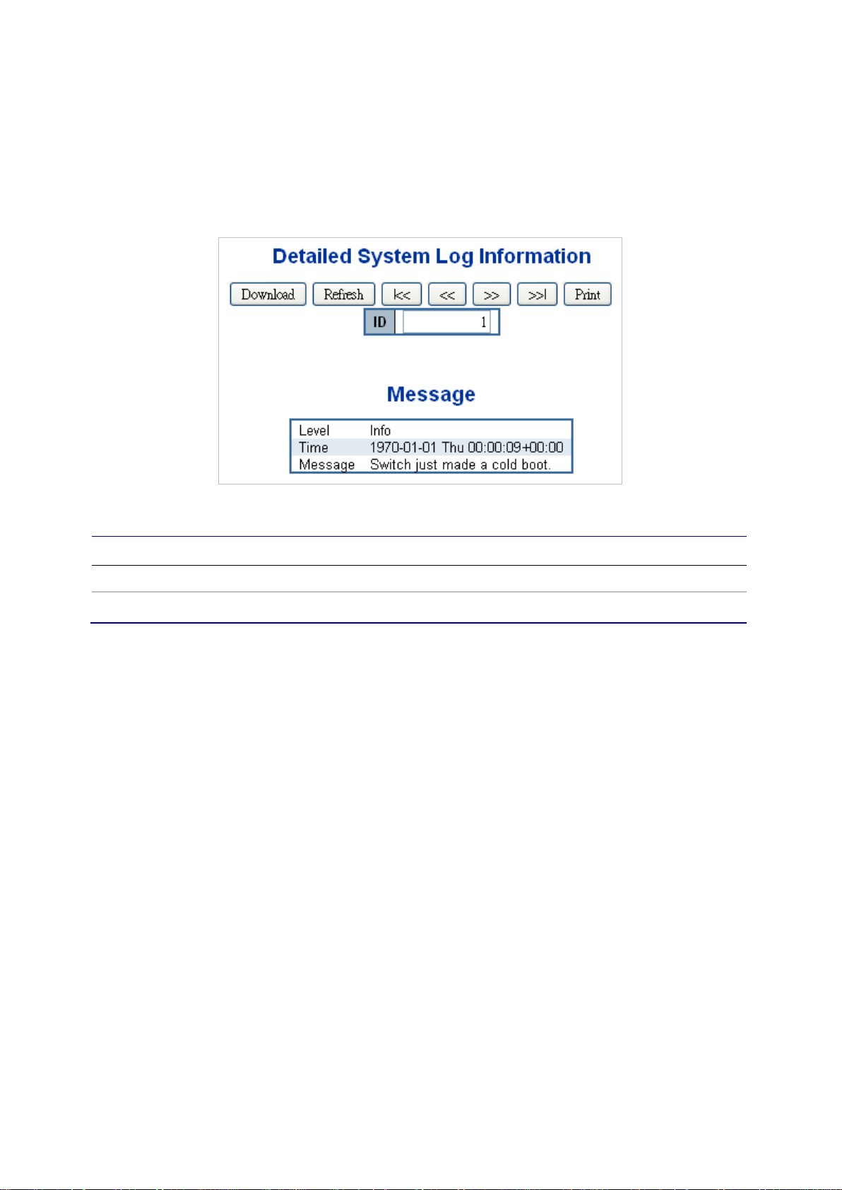
Chapter 4: Web configuration
• Click >>I to update the system log entries, ending at the last available entry ID.
Detailed log
The Detailed System Log Information page displays the managed switch system log
information details.
The page includes the following fields:
Object Description
ID The ID (>= 1) of the system log entry.
Message The message of the system log entry.
Buttons
• Click Download to download the system log entry to the current entry ID.
• Click Refresh to update the system log entry to the current entry ID.
• Click I<< to update the system log entries, starting from the first available entry ID.
• Click << to update the system log entries, ending at the last entry currently
displayed.
• Click >> to update the system log entries, starting from the last entry currently
displayed.
• Click >>I to update the system log entries, ending at the last available entry ID.
• Click Print to print the system log entry to the current entry ID.
Remote syslog
The System Log Configuration page displays the managed switch remote system log
information details.
56 NS4702-24P-4X Managed Switch User Manual
Page 59

Chapter 4: Web configuration
The page includes the following fields:
Object Description
Mode Indicates the server mode operation. When the mod e operation is
enabled, the syslog message is sent to the syslog ser ver. The syslog
protocol is based on UDP communication and recei ved on UDP port
514. The syslog server will not send acknowledgments back to
sender since UDP is a connectionless protocol and it does not
provide acknowledgments. The syslog packet is al ways sent out even
if the syslog server does not exist. Selections include:
Enabled: Enable remote syslog mode operation.
Disabled: Disable remote syslog mode operation.
Syslog Server IP Indicates the IPv4 host address of syslog server. If the switch
provides the DNS feature, it also can be a host name.
Syslog Level Indicates what kind of message is sent to the syslog server.
Selections include:
Info: Send information, warnings, and errors.
Warning: Send warnings and errors.
Error: Send errors.
Buttons
• Click Apply to apply changes.
• Click Reset to undo any changes made locally and revert to previously saved
values.
SMTP configuration
The SMTP Configuration page displays the managed switch SMTP configuration
details.
NS4702-24P-4X Managed Switch User Manual 57
Page 60

Chapter 4: Web configuration
The page includes the following fields:
Object Description
SMTP Mode Controls whether or not SMTP is enabled on the switch.
SMTP Server Type the SMTP server nam e or the IP address of the SMTP server.
SMTP Port Set the port number of SMTP service.
SMTP Authentication SMTP authentication is ena bl ed if selected. Authentication is required
when an email is sent.
Authentication User Name Type the user name for the SMTP server if Authent i cat i on i s Enable.
Authentication Password Type the password for the SMTP server if Authentication is Enable.
E-mail From Type the sender’s email address. This address is used for reply
emails.
E-mail Subject Type the subject/title of the email.
E-mail 1 To / E-mail 2 To Type the receiver’s email address.
Buttons
• Click test to send a test mail to the mail server to indicate if the account is available.
• Click Save to save changes.
• Click Reset to undo any changes made locally and revert to previously saved
values.
Web firmware upgrade
Update the managed switch firmware using the Firmware Upload page.
58 NS4702-24P-4X Managed Switch User Manual
Page 61

Chapter 4: Web configuration
To open the Firmware Upload page:
1. Click System > W eb Firmware Upgrade. The Firmware Upload page appears.
2. Click the Browse button on the main page. The file selection menu to choose
firmware appears.
3. Select the firmware file and then click Upload. The Software Upload Progress
displays the file with upload status.
4. After the software is uploaded to the system successfully, the following screen
appears. The system loads the new software after reboot.
Note: DO NOT Power OFF the managed switch until the update progress is
completed.
Note: Do not quit the Firmware Upgrade page without clicking the OK button after the
image is loaded. Otherwise, the system won’t apply the new firmware and the user has
to repeat the firmware upgrade process.
Save startup configuration
This function ensures that the current active configuration can be used after the next
reboot.
After clicking Save Configuration, the following screen appears.
NS4702-24P-4X Managed Switch User Manual 59
Page 62

Chapter 4: Web configuration
Configuration download
The managed switch stores its configuration in a number of text files in CLI format. The
files are either virtual (RAM-based) or stored in flash on the switch.
There are three system files:
• running-config: A virtual file that represents the currently active configuration on
the switch. This file is volatile.
• startup-config: The startup configuration for the switch, read at boot time.
• default-config: A read-only file with vendor-specific configuration. This file is read
when the system is restored to default settings.
It is also possible to store up to two other files and apply them to running-config,
thereby switching configuration.
The Download Configuration page permits the download of the running-config, startupconfig, and default-config system files to the switch.
Configuration upload
The Upload Configuration page permits the upload of the running-config and startupconfig to the switch.
60 NS4702-24P-4X Managed Switch User Manual
Page 63

Chapter 4: Web configuration
If the destination is running-config, the file will be applied to the switch configuration.
This can be done in two ways:
• Replace mode: The current configuration is fully replaced with the configuration in
the uploaded file.
• Merge mode: The uploaded file is merged into running-config.
If the file system is full (i.e., it contains the system files mentioned above plus two other
files), it is not possible to create new files unless an existing file is overwritten or
another is deleted first.
Configuration activate
The Activate Configuration page permits activation of the startup-config and defaultconfig files on the switch.
It is possible to activate any of the configuration files present on the switch, except for
running-config which represents the currently active configuration.
Select the file to activate and click Activate Configuration. This initiates the process of
completely replacing the existing configuration with that of the selected file.
NS4702-24P-4X Managed Switch User Manual 61
Page 64

Chapter 4: Web configuration
Configuration delete
The Delete Configuration page permits the deletion of the startup-config and defaultconfig files which are stored in Flash memory. If this is performed and the switch is
rebooted without a prior save operation, it effectively resets the switch to default
configuration.
Image select
This page provides information about the active and alternate (backup) firmware
images in the device, and allows you to revert to the alternate image. The web page
displays two tables with information about the active and alternate firmware images.
Note: If the active firmware image is the alternate image, only the "Active Image" table
is shown. In this case, the Activate Alternate Image button is also disabled.
Note:
1. If the alternate image is active (due to a corruption of the primary image or by
manual intervention), uploading a new firmware image to the device will activate
the primary image slot and use it instead.
2. The firmware version and date information may be empty for older firmware
releases. This does not constitute an error.
62 NS4702-24P-4X Managed Switch User Manual
Page 65

Chapter 4: Web configuration
The page includes the following fields:
Object Description
Image The flash index name of the firmware image. The name of primary
(preferred) image is image, the alternate image i s named image.bk.
Version The version of the firmware image.
Date The date when the firmware was produced.
Buttons
• Click Activate Alternate Image to use the alternate image. This button may be
disabled depending on the system state.
System reboot
The Restart Device page permits the device to be rebooted from a remote location.
After clicking the Yes button to restart, log in to the web interfac e about 60 seconds
later.
Buttons
• Click Yes to reboot the system.
• Click No to return to the Port State page without rebooting the system.
Note: You can also check the SYS LED on the front panel to identify whether of not the
system is loaded completely. If the SYS LED is blinking, then it is in the firmware load
stage; if the SYS LED light is on, you can use the web browser to log in to the managed
switch.
DHCP server
Mode
The DHCP Server Excluded IP Configuration page offers permits exclusion of IP
addresses for static IP address devices, such as servers or routesr. The DHCP server
will not allocate these excluded IP addresses to the DHCP client.
NS4702-24P-4X Managed Switch User Manual 63
Page 66

Chapter 4: Web configuration
The page includes the following fields:
Object Description
Delete Permits deletion of an IP range.
IP Range Defines the IP address range to be excluded. The first excluded IP
must be smaller than or equal to the second exclude d IP. If the IP
range contains only 1 excluded IP, input it to eit her one of the first
and second excluded IPs or both.
Buttons
• Click Add IP Range to add an IP range.
• Click Apply to apply changes.
• Click Reset to undo any changes made locally and revert to previously saved
values.
Pool
The DHCP Server Pool Configuration page manages DHCP pools. According to the
DHCP pool, the DHCP server will allocate IP addresses and deliver configuration
parameters to the DHCP client. Adding a pool and giving it a name creates a new pool
with a default configuration. If you want to configure all settings including type, IP
subnet mask, and lease time, click the pool name to go into the configuration page.
64 NS4702-24P-4X Managed Switch User Manual
Page 67
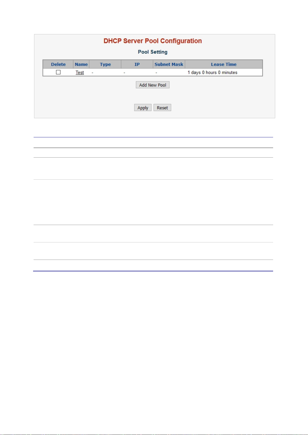
Chapter 4: Web configuration
The page includes the following fields:
Object Description
Delete Permits deletion of pool settings.
Name Configure the pool name that accepts all printable characters, except
white space. If you want to configure the detail sett i ngs, click the pool
name to go into the configuration page.
Type Indicates the pool type.
Network: The pool defines a pool of IP addresses to service more
than one DHCP client.
Host: the pool services for a specific DHCP client identified by client
identifier or hardware address.
If "-" appears, it means not defined.
IP Indicates the network number of the DHCP address pool.
If "-" appears, it means not defined.
Subnet Mask Indicates the subnet mask of the DHCP address pool.
If "-" appears, it means not defined.
Lease Time Indicates the lease time of the pool.
Buttons
• Click Add New Pool to add a new DHCP pool.
• Click Apply to apply changes.
• Click Reset to undo any changes made locally and revert to previously saved
values.
Click a pool name to configure DHCP pool settings on the DHCP Pool Configuration
page.
NS4702-24P-4X Managed Switch User Manual 65
Page 68

Chapter 4: Web configuration
66 NS4702-24P-4X Managed Switch User Manual
Page 69

Chapter 4: Web configuration
The page includes the following fields:
Object Description
Name Select a pool by pool name.
Pool Name Indicates the selected pool name.
Type Specifies the pool type.
Network: the pool defines a pool of IP addresses to service more
than one DHCP client.
Host: the pool services for a specific DHCP client identified by client
identifier or hardware address.
IP Indicates the specific network number of the DHCP address pool.
Subnet Mask DHCP option 1.
Specifies the subnet mask of the DHCP address pool.
Lease Time DHCP option 51, 58 and 59.
Specifies the lease time that allows the client to request a lease time
for the IP address. If all are 0's, then it means the lease time is
infinite.
NS4702-24P-4X Managed Switch User Manual 67
Page 70

Chapter 4: Web configuration
Specifies the vendor specific information according to the option 60
Object Description
Domain Name DHCP option 15.
Specifies a domain name that the client should use when resolving a
hostname via DNS.
Broadcast Address DHCP option 28.
Specifies the broadcast address in use on the client's subnet.
Default Router DHCP option 3.
Specifies a list of IP addresses for routers on the client's subnet.
DNS Server DHCP option 6.
Specifies a list of Domain Name System name servers available to
the client.
NTP Server DHCP option 42.
Specifies a list of IP addresses indicating NTP servers available to
the client.
NetBIOS Node Type DHCP option 46.
Specifies NetBIOS node type option to allow Netbios over TCP/IP
clients which are configurable as described in RFC 1 001/ 1002.
NetBIOS Scope DHCP option 47.
Specifies the NetBIOS over TCP/IP scope parameter for the client as
specified in RFC 1001/1002.
NetBIOS Name Server DHCP option 44.
Specifies a list of NBNS name servers listed in order of preference.
NIS Domain Name DHCP option 40.
Specifies the name of the client's NIS domain.
NIS Server DHCP option 41.
Specifies a list of IP addresses indicating NIS servers avai labl e to the
client.
Client Identifier DHCP option 61.
Specifies the client's unique identifier to be used when the pool is the
type of host. Select the type of client identifier at first.
None: client identifier is not specified yet.
Name: the type of client identifier is other than hardware.
MAC: the type of client identifier is MAC address.
Hardware Address Specifies the client's hardware (MAC) address to be used when the
pool is the type of host.
Client Name DHCP option 12.
Specifies the name of client to be used when the pool is the type of
host.
Vendor 1 Class Identifier DHCP option 60.
Specifies the identifier to be used by the DHCP client to optionally
identify the vendor type and configuration of a DHCP cli ent. The
DHCP server delivers the corresponding option 43 specific
information to the client that sends an option 60 vendor class
identifier.
Vendor 1 Specific
DHCP option 43.
Information
68 NS4702-24P-4X Managed Switch User Manual
Page 71

Chapter 4: Web configuration
vendor class identifier.
Object Description
Vendor 2 Class identifier DHCP option 60.
Specifies the identifier to be used by the DHCP client to optionally
identify the vendor type and configuration of a DHCP cli ent. The
DHCP server delivers the corresponding option 43 specific
information to the client that sends the option 60 vendor class
identifier.
Vendor 2 Specific
Information
Vendor 3 Class Identifier DHCP option 60.
Vendor 3 Specific
Information
Vendor 4 Class Identifier DHCP option 60.
Vendor 4 Specific
Information
DHCP option 43.
Specifies vendor specific information according to the option 60
vendor class identifier.
Specifies the identifier to be used by the DHCP client to optionally
identify the vendor type and configuration of a DHCP cli ent. The
DHCP server delivers the corresponding option 43 specific
information to the client that sends the option 60 vendor class
identifier.
DHCP option 43.
Specify vendor specific information according to the option 60 vendor
class identifier.
Buttons
• Click Apply to apply changes.
• Click Reset to undo any changes made locally and revert to previously saved
values.
Statistics
The DHCP Server Statistics page displays the database counters and the number of
DHCP messages sent and received by the DHCP server.
NS4702-24P-4X Managed Switch User Manual 69
Page 72

Chapter 4: Web configuration
The page includes the following fields:
Database counters
Displays the counters of various databases.
Object Description
Automatic Binding Number of bindings with network-type pools.
Manual Binding Number of bindings that the administrator assigns an IP address to a
client (host pool type).
Expired Binding Number of bindings in which the lease time expire d or they are
cleared from Automatic/Manual type bindings.
Binding counters
Displays the counters of various bindings.
Object Description
Automatic Binding Number of bindings with network-type pools.
Manual Binding Number of bindings that the administrator assigns an IP address to a
client (host pool type).
Expired Binding Number of bindings in which the lease time expire d or they are
cleared from Automatic/Manual type bindings.
70 NS4702-24P-4X Managed Switch User Manual
Page 73

Chapter 4: Web configuration
DHCP message received counters
Displays the counters of DHCP messages received by the DHCP server.
Object Description
Discover Number of DHCP DISCOVER messages received.
Request Number of DHCP REQUEST messages received.
Decline Number of DHCP DECLINE message s received.
Release Number of DHCP RELEASE messages received.
Inform Number of DHCP INFORM messages received.
DHCP message sent counters
Displays the counters of DHCP messages sent by the DHCP server.
Object Description
Offer Number of DHCP OFFER messages sent.
Ack Number of DHCP ACK messages sent.
Nak Number of DHCP NAK messages sent.
Buttons
• Select the Auto-refresh check box to refresh the page automatically. Autom atic
refresh occurs every three seconds.
• Click Refresh to refresh the page immediately.
• Click Clear to clear DHCP message received and sent counters.
Binding
The DHCP Server Binding IP page displays bindings generated for DHCP clients.
The page includes the following fields:
Binding IP address
Displays all bindings.
NS4702-24P-4X Managed Switch User Manual 71
Page 74

Chapter 4: Web configuration
Object Description
IP IP address allocated to the DHCP client.
Type Type of binding. Possible types are Automatic, Manual, Expired.
State St ate of binding. Possible states are Committed, Allocated, Expired.
Pool Name The pool that generates the binding.
Server ID Server IP address that services the binding.
Buttons
• Select the Auto-refresh check box to refresh the page automatically. Automatic
refresh occurs every three seconds.
• Click Refresh to refresh the page immediately.
• Click Clear Selected to clear the selected bindings. If the select ed binding is
Automatic or Manual, then it is changed to Expired. If the selected binding is
Expired, then it is freed.
• Click Clear Automatic to clear all automatic bindings and change them to Expired
bindings.
• Click Clear Manual to clear all manual bindings and change them to Expired
bindings.
• Click Clear Expired to clear all expired bindings and free them.
Declined IP
The DHCP Server Declined IP page displays declined IP addresses.
The page includes the following fields:
Declined IP address
Displays IP addresses declined by DHCP clients.
Object Description
Declined IP List of IP addresses declined.
72 NS4702-24P-4X Managed Switch User Manual
Page 75

Chapter 4: Web configuration
Buttons
• Select the Auto-refresh check box to refresh the page automatically. Automatic
refresh occurs every three seconds.
• Click Refresh to refresh the page immediately.
Detailed statistics
The DHCP Detailed Statistics page provides statistics for DHCP snooping. Note that
the normal forward per-port TX statistics are not increased if the incoming DHCP
packet is done by a L3 forwarding mechanism. Clearing the statistics on a specific port
may not affect global statistics since it gathers a different layer overview.
The page includes the following fields:
Object Description
RX and TX Discover The number of discover (option 53 wit h value 1) packets received and
transmitted.
RX and TX Offer The number of offer (option 53 with value 2) packets received and
transmitted.
RX and TX request The number of request (option 53 with value 3) packets received and
transmitted.
RX and TX Decline The number of decli ne (option 53 with value 4) packets received and
transmitted.
RX and TX ACK The number of ACK (option 53 with value 5) packets received and
transmitted.
RX amd TX NAK The number of NAK (option 53 with value 6) packets received and
transmitted.
RX and TX Release The number of release (option 53 with value 7) packets received and
transmitted.
RX and TX Inform The number of inform (option 53 with value 8) packets received and
transmitted.
NS4702-24P-4X Managed Switch User Manual 73
Page 76

Chapter 4: Web configuration
Object Description
RX and TX Lease Query The number of lease query (option 53 with value 10) packets
received and transmitted.
RX and TX Lease
Unassigned
RX and TX Lease Unknown The number of lease unknown (option 53 with value 12) packets
RX and TX lease Active The number of lease active (option 53 with value 13) packets
RX Discarded Checksum
Error
RX Discarded from
Untrused
The number of lease unassigned (option 53 with val ue 11) packets
received and transmitted.
received and transmitted.
received and transmitted.
The number of discarded packets where IP/UDP checksum is in
error.
The number of discarded packets that are coming from an untrusted
port.
Buttons
• Select the Auto-refresh check box to refresh the page automatically. Automatic
refresh occurs every three seconds.
• Click Refresh to refresh the page immediately.
• Click Clear to clear the counters for the selected por t .
UDLD
The UDLD Port Configuration page permits the user to inspect and change the current
Unidirectional Link Detection (UDLD) configurations.
74 NS4702-24P-4X Managed Switch User Manual
Page 77
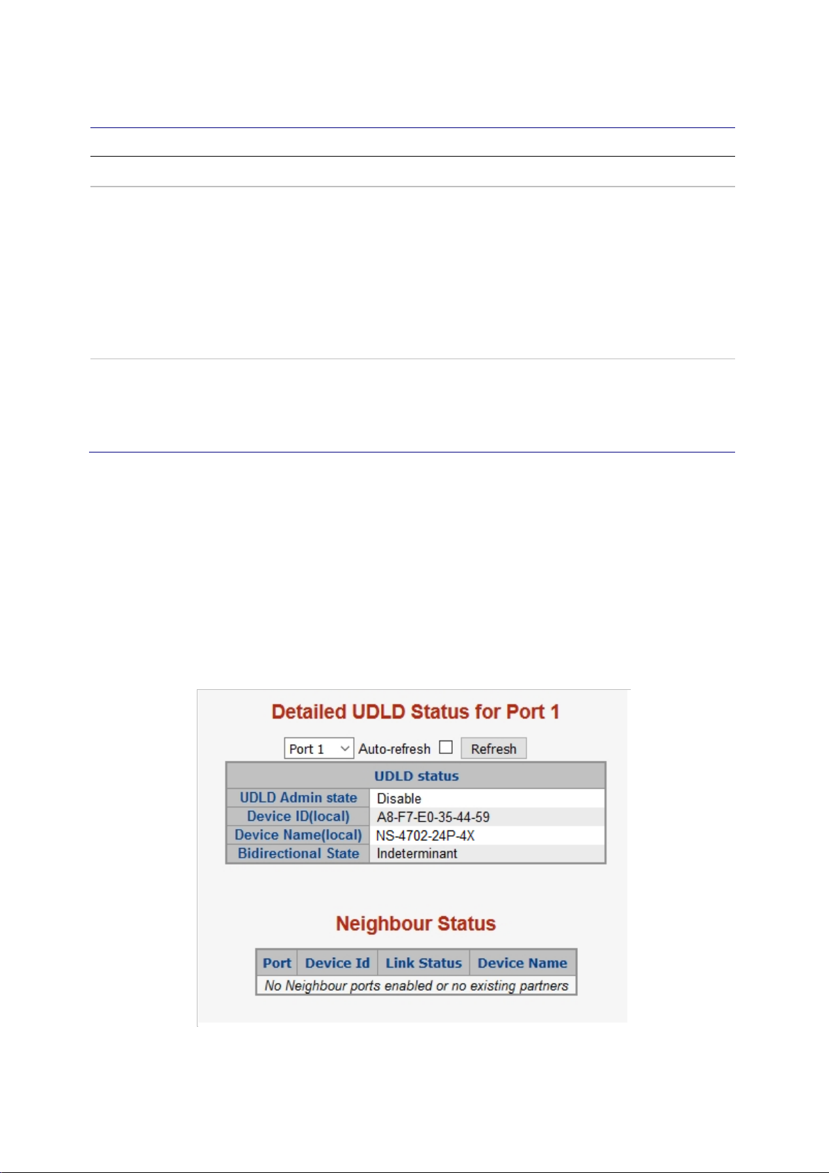
Chapter 4: Web configuration
The page includes the following fields:
Object Description
Port Port number of the switch.
UDLD Mode Configures the UDLD mode on a port. Sel ect i ons inlcude Disable,
Normal and Aggressive. Default mode is Disable.
Disable – In disabled mode, UDLD functionality doesn't exist on the
port.
Normal – In normal mode, if the link state of the port was determined
to be unidirectional, it will not affect the port state.
Aggressive – In aggressive mode, unidirectional detected ports will
get shut down. To bring back the ports up, disable UDLD on the
ports.
Message Interval Configures the period of time between UDLD probe messages on
ports that are in the advertisement phase and are determined to be
bidirectional. The range is from 7 to 90 seconds (def ault value is 7
seconds). Currently, the default time interval is supported due to lack
of detailed information in RFC 5171.
Buttons
• Click Save to save changes.
• Click Reset to undo any changes made locally and revert to previously saved
values.
UDLD status
The Detailed UDLD Status/Neighbor Status page displays the UDLD status of the
ports.
NS4702-24P-4X Managed Switch User Manual 75
Page 78

Chapter 4: Web configuration
UDLD port status
The page includes the following fields:
Object Description
UDLD Admin State The current port state of the logical port, Enabled if any of
state(Normal,Aggressive) is Enabled.
Device ID (Local) The ID of Device.
Device Name (Local) Name of the Device.
Bidirectional State The current state of the port.
Neighbor status
The page includes the following fields:
Object Description
Port The current port of the neighbor device.
Device ID The current ID of the neighbor device.
Link Status The current link status of the neighbor port.
Device Name Name of the neighbor device.
Buttons
• Select the Auto-refresh check box to refresh the page automatically. Automatic
refresh occurs every three seconds.
• Click Refresh to refresh the page immediately.
Simple Network Manageme nt Pr o t ocol (SNMP)
SNMP overview
The Simple Network Management Protocol (SNMP) is an application layer protocol that
facilitates the exchange of management information between network devices. It is part
of the Transmission Control Protocol/Internet Protocol (TCP/IP) protocol suite. SNMP
permits network administrators to manage network performance, find and solve networ k
problems, and plan for network growth.
An SNMP-managed network consists of the following:
• Network management stations (NMSs): Sometimes called consoles, these
devices execute management applications that monitor and control network
elements. Physically, NMSs are usually engineering workstation-caliber computers
with fast CPUs, megapixel color displays, substantial memory, and abundant disk
space. At least one NMS must be present in each managed environment.
76 NS4702-24P-4X Managed Switch User Manual
Page 79

Chapter 4: Web configuration
• Agents: Agents are software modules that reside in network elements. They collect
and store management information such as the number of error packets received by
a network element.
• Management information base (MIB): An MIB is a collection of managed objects
residing in a virtual information store. Collections of related managed objects are
defined in specific MIB modules.
• Network-management protocol: A management protocol is used to convey
management information between agents and NMSs. SNMP is the Internet
community's de facto standard management protocol.
SNMP operations
SNMP itself is a simple request/response protocol. NMSs can send multiple requests
without receiving a response.
• Get – Allows the NMS to retrieve an object instance from the agent.
• Set – Allows the NMS to set values for object instances within an agent.
• Trap – Used by the agent to asynchronously inform the NMS of some event. The
SNMPv2 trap message is designed to replace the SNMPv1 trap message.
SNMP community
An SNMP community is the group that devices and management stations running
SNMP belong to. It helps define where information is sent. The community name is
used to identify the group. An SNMP device or agent may belong to more than one
SNMP community. It will not respond to requests from management stations that do not
belong to one of its communities. SNMP default communities are:
• Write (private)
• Read (public)
Use the SNMP Menu to display or configure the managed switch's SNMP funct io n. This
section has the following items:
System Configuration Configure SNMP on this page.
Trap Destination
Configuration
Trap Source Configuration Configure SNMP trap source on this page.
NS4702-24P-4X Managed Switch User Manual 77
Configure SNMP trap on this page.
Page 80

Chapter 4: Web configuration
System Information The system information is provided here.
SNMPv3 Communities Configure SNMPv3 communities table on this page.
SNMPv3 Users Conf igure SNMPv3 users table on this page.
SNMPv3 Groups
SNMPv3 Views Configure SNMPv3 views table on this page.
SNMPv3 Access Configure S NMPv3 accesses table on this page.
Configure SNMPv3 groups table on this page.
SNMP system configuration
Configure SNMP on the SNMP System Configuration page.
The page includes the following fields:
Object Description
Mode Indicates the SNMP mode operation. Selections include:
Enabled: Enable SNMP mode operation.
Disabled: Disable SNMP mode operation.
Engine ID Indicates the SNMPv3 engine ID. The string must contain an even
number between 10 and 64 hexadecimal digits, but al l-zeros and all'F's are not allowed. Change of the Engine ID will clear all original
local users.
Buttons
• Click Apply to apply changes.
• Click Reset to undo any changes made locally and revert to previously saved
values.
78 NS4702-24P-4X Managed Switch User Manual
Page 81

Chapter 4: Web configuration
SNMP trap configuration
Configure the SNMP trap on the SNMP Trap Configuration page.
The page includes the following fields:
Object Description
Trap Config Indicates the trap configuration name. The allowed string length is 0
to 255, and the allowed content is ASCII characters from 33 to 126.
Trap Mode Indicates the SNMP trap mode operation. Selections include:
Enabled: Enable SNMP trap mode operation.
Disabled: Disable SNMP trap mode operation.
Trap Version Indicates the SNMP trap supported version. Sel ect i ons include:
SNMP v1: Set SNMP trap supported version 1.
SNMP v2c: Set SNMP trap supported version 2c.
SNMP v3: Set SNMP trap supported version 3.
Write Community Indicates the community write access string to permit access to the
SNMP agent. The allowed string length is 0 to 255, and the allowed
content is the ASCII characters from 33 to 126.
The field is applicable only when the SNMP version is SNMPv1 or
SNMPv2c. If the SNMP version is SNMPv3, the community string will
be associated with the SNMPv3 communities table. It provides more
flexibility to configure a security name than a SNMPv1 or SNMPv2c
community string. In addition to the community st ring, a particular
range of source addresses can be used to restrict the source subnet.
Trap Community Indicates the community access string when sending the SNMP trap
packet. The allowed string length is 0 to 255, and the al lowed content
is the ASCII characters from 33 to 126.
NS4702-24P-4X Managed Switch User Manual 79
Page 82

Chapter 4: Web configuration
Object Description
Trap Destination Address Indicates the SNMP trap destination address. It allows a valid IP
address in dotted decimal notation ('x.y.z.w') as well as a valid
hostname. A valid hostname is a string drawn from the alphabet (AZa-z), digits (0-9), dot (.), dash (-). Spaces are not allowed, the first
character must be an alpha character, and the first and last
characters must not be a dot or a dash.
Indicates the SNMP trap destination IPv6 address. IPv6 address is in
128-bit records represented as eight fields of up to f our hex adecimal
digits with a colon separating each field (:). For example,
'fe80::215:c5ff:fe03:4dc7'. The symbol ': :' is a special syntax that can
be used as a shorthand way of representing multiple 16-bi t groups of
contiguous zeros; but it can appear only once. It can also represent a
legally valid IPv4 address. For example, '::192. 1.2.34'.
Trap Destination Port Indicates the SNMP trap destination port. The SNMP agent sends an
SNMP message via this port. The port range is 1~65535.
Trap Inform Mode Indicates the SNMP trap inform mode operation. Selections include:
Enabled: Enable SNMP trap authentication failure.
Disabled: Disable SNMP trap authentication failure.
Trap Inform Timeout
(seconds)
Trap Inform Retry Times Indicates the SNMP trap inform retry times. The allowed range is 0 to
Trap Probe Security Engine
ID
Trap Security Engine ID Indicates the SNMP trap security engine ID. SNMPv3 sends traps
Trap Security Name Indicates the SNM P trap security name. SNMPv3 traps and informs
Indicates the SNMP trap inform timeout. The allowed range is 0 to
2147.
255.
Indicates the SNMPv3 trap probe security engine ID mode of
operation. Selections include:
Enabled: Enable SNMP trap probe security engine ID mode of
operation.
Disabled: Disable SNMP trap probe security engine ID mode of
operation.
and informs using USM for authentication and privacy. A unique
engine ID for these traps and informs is needed. When Trap Probe
Security Engine ID is enabled, the ID will be probed automatically.
Otherwise, the ID specified in this field is used. Th e st ring must
contain an even number (in hexadecimal format) with number of
digits between 10 and 64, but all zeros and all-'F's ar e not allowed.
using USM for authentication and privacy. A unique security name is
needed when traps and informs are enabled.
Buttons
• Click Apply to apply changes.
• Click Reset to undo any changes made locally and revert to previously saved
values.
SNMP system information
The switch system information is provided in the System Information Configuration
page.
80 NS4702-24P-4X Managed Switch User Manual
Page 83

Chapter 4: Web configuration
The page includes the following fields:
Object Description
System Contact The textual identification of the contact person for this managed node
and information on how to contact this person. The allowed string
length is 0 to 255, and the allowed content is the AS CI I characters
from 32 to 126.
System Name An administratively assign ed name for this managed node. By
convention, this is the node's fully-qualified dom ain name. A domain
name is a text string drawn from the alphabet (A-Za-z), digits (0-9),
minus sign (-). No space characters are permitted as part of a name.
The first character must be an alpha character. And the first or last
character must not be a minus sign. The allowed string length is 0 to
255.
System Location The physical location of this node (e.g., telephone closet, 3rd floor).
The allowed string length is 0 to 255, and the allowed content is the
ASCII characters from 32 to 126.
Buttons
• Click Apply to apply changes.
• Click Reset to undo any changes made locally and revert to previously saved
values.
Trap source configuration
Configure SNMP trap source configuration on the Trap Configuration page. You don’t
need to configure the subset OID if you want to apply this trap to the whole SNMP OID.
For example, if you want to apply a trap for any port “link down” or “link up,” then
configure them like as in the screen below. If you want to apply link up or link down to
one of ports, input the SNMP OID to the subset OID column. For example, if you want
apply a link down trap to port1, input “10000001” in the linkDown entry.
NS4702-24P-4X Managed Switch User Manual 81
Page 84

Chapter 4: Web configuration
The page includes the following fields:
Object Description
Delete Select the check box to delete the entry. It will be deleted during the
next save.
Name Indicates the name for the entry.
Type The filter type for the entry. Selections include:
included: An optional flag to indicate a trap is sent for the given trap
source is matched.
excluded: An optional flag to indicate a trap is not sent for the given
trap source is matched.
Subset OID The subset OID for the entry. The value depends on the trap name
type. For example, the ifIdex is the subset OID of li nkUp and
linkDown. A valid subset OID is one or more digital nu m bers (0-
4294967295) or asterisk(*) which are separated by dots(.). The first
character must not begin with an asterisk (*) and the m aximum of
OID count must not exceed 128.
Buttons
• Click Add New Entry to add a new community entry.
• Click Apply to apply changes.
• Click Reset to undo any changes made locally and revert to previously saved
values.
82 NS4702-24P-4X Managed Switch User Manual
Page 85

Chapter 4: Web configuration
SNMPv3 configuration
SNMPv3 communities
Configure SNMPv3 communities in the SNMPv3 Community Configuration page. The
entry index key is Community.
The page includes the following fields:
Object Description
Delete Select the check box to delete the entry. It will be deleted during the
next save.
Community Name Indicates the security name t o m ap the community to the SNMP
Groups configuration. The allowed string length is 1 to 32, and the
allowed content is ASCII characters from 33 to 126.
Community Secret Indicates the community secret (access string) to permit access us i ng
SNMPv1 and SNMPv2c to the SNMP agent. The allo wed string
length is 1 to 32, and the allowed content is ASCII characters from 33
to 126.
Source IP Indicates the SNMP access source ad dress. A particular range of
source addresses can be used to restrict the source subnet when
combined with the source mask.
Source Mask Indicates the SNMP access source address mask.
Buttons
• Click Add New Entry to add a new community entry.
• Click Apply to apply changes.
• Click Reset to undo any changes made locally and revert to previously saved
values.
SNMPv3 users
Configure SNMPv3 users on the SNMPv3 User Configuration page. The entry index
keys are Engine ID and User Name.
NS4702-24P-4X Managed Switch User Manual 83
Page 86

Chapter 4: Web configuration
The page includes the following fields:
Object Description
Delete Select Delete to delete the entry. It will be deleted during t he next
save.
Engine ID An octet string identifying the engine ID that thi s ent ry should belong
to. The string must contain an even number (in hexadecim al f ormat)
with a number of digits between 10 and 64, but all zeros an d all 'F 's
are not allowed. The SNMPv3 architecture uses t he Us er-based
Security Model (USM) for message security and the V i ew-based
Access Control Model (VACM) for access control. For the USM entry,
the usmUserEngineID and usmUserName are the entry's keys.
In a simple agent, usmUserEngineID is always the same as the
snmpEngineID value. The value can also take the value of the
snmpEngineID of a remote SNMP engine with which t hi s user can
communicate. In other words, if user engine ID eq ual system engine
ID then it is local user, otherwise it is a remote user.
User Name A string identifying the user name that this entry shoul d bel ong to.
The allowed string length is 1 to 32, and the allowed c ont ent is ASCII
characters from 33 to 126.
Security Level Indicates the security model that this entry should belong to.
Selections include:
NoAuth, NoPriv: None authentication and none priv acy .
Auth, NoPriv: Authentication and none privacy.
Auth, Priv: Authentication and privacy.
The value of the security level cannot be modified i f the entry already
exists. Ensure that the value is set correctly.
Authentication Protocol Indicates the authentication protocol that this entry should bel ong to.
Selections include:
None: None authentication protocol.
MD5: An optional flag to indicate that this user using M D5
authentication protocol.
SHA: An optional flag to indicate that this user using SHA
authentication protocol.
The value of security level cannot be modified if the entry already
exists. Ensure that the value is set correctly.
Authentication Password A string identifying the authentication pass phrase. For MD5
authentication protocol, the allowed string length is 8 to 32. For SHA
authentication protocol, the allowed string length is 8 to 40. The
allowed content is the ASCII characters from 33 to 126.
Privacy Protocol Indicates the privacy protocol that this entry should belong to.
Selections include:
None: None privacy protocol.
84 NS4702-24P-4X Managed Switch User Manual
Page 87

Chapter 4: Web configuration
DES: An optional flag to indicate that this user using DES
Object Description
authentication protocol.
AES: An optional flag to indicate that this user uses AE S
authentication protocol.
Privacy Password A string identify i ng the privacy pass phrase. The allowed string length
is 8 to 32, and the allowed content is the ASCII characters from 33 to
126.
Buttons
• Click Add New Entry to add a new user entry.
• Click Apply to apply changes.
• Click Reset to undo any changes made locally and revert to previously saved
values.
SNMPv3 groups
Configure SNMPv3 groups on the SMNPv3 Group Configuration page. The entry index
keys are Security Model and Security Name.
NS4702-24P-4X Managed Switch User Manual 85
Page 88

Chapter 4: Web configuration
The page includes the following fields:
Object Description
Delete Select Delete to delete the entry. It will be deleted during t he next
save.
Security Model Indicates the security model that this entry should belong to.
Selections include:
v1: Reserved for SNMPv1.
v2c: Reserved for SNMPv2c.
usm: User-based Security Model (USM).
Security Name A string identifying the security name that this entry should belong t o.
The allowed string length is 1 to 32, and the allowed c ont ent is the
ASCII characters from 33 to 126.
Group Name A string identifying the group name that this entry sho ul d bel ong to.
The allowed string length is 1 to 32, and the allowed c ont ent is the
ASCII characters from 33 to 126.
Buttons
• Click Add New Entry to add a new group entry.
• Click Apply to apply changes.
• Click Reset to undo any changes made locally and revert to previously saved
values.
SNMPv3 views
Configure SNMPv3 views table in the SNMPv3 View Configuration page. The entry
index keys are View Name and OID Subtree.
The page includes the following fields:
Object Description
Delete Select Delete to delete the entry. It will be deleted during t he next
save.
View Name A string identifies the view nam e that this entry should belong to. The
allowed string length is 1 to 32, and the allowed content is the ASCII
characters from 33 to 126.
View Type Indicates the view type that this entry should belong to. Selections
include:
included: An optional flag to indicate that this view subtree should be
included.
86 NS4702-24P-4X Managed Switch User Manual
Page 89

Chapter 4: Web configuration
excluded: An optional flag to indicate that t his view subtree should
Object Description
be excluded.
In general, if a view entry's view type is excluded, it should exist in
another view entry in which the view type is included and it's OID
subtree overrides the excluded view entry.
OID Subtree The OID defining the root of the subtree to add to the named view.
The allowed OID length is 1 to 128. The allowed string content is
digital number or asterisk (*).
Buttons
• Click Add New Entry to add a new view entry.
• Click Apply to apply changes.
• Click Reset to undo any changes made locally and revert to previously saved
values.
SNMPv3 access
Configure SNMPv3 access on the SNMPv3 Access Configuration page. The entry
index keys are Group Name, Security Model, and Security Level.
The page includes the following fields:
Object Description
Delete Select Delete to delete the entry. It will be deleted during t he next
save.
Group Name A string identifies the group name that this entry should bel ong to.
The allowed string length is 1 to 32, and the allowed c ont ent is the
ASCII characters from 33 to 126.
Security Model Indicates the security model that this entry should belong to.
Selections include:
any: Accepted any security model (v1, v2c, usm).
v1: Reserved for SNMPv1.
v2c: Reserved for SNMPv2c.
usm: User-based Security Model (USM)
Security Level Indicates the security model that this entry should belong to.
Selections include:
NoAuth, NoPriv: None authentication and none priv acy .
Auth, NoPriv: Authentication and none privacy.
Auth, Priv: Authentication and privacy.
NS4702-24P-4X Managed Switch User Manual 87
Page 90

Chapter 4: Web configuration
Object Description
Read View Name The name of the MIB view defining the MIB objects for which this
request may request the current values. The allowed string length is 1
to 32, and the allowed content is the ASCII characters from 33 to 126.
Write View Name The name of the MIB view defining the MIB objects for which this
request may potentially SET new values. The all owed string length is
1 to 32, and the allowed content is the ASCII characters f rom 33 to
126.
Buttons
• Click Add New Entry to add a new access entry.
• Click Apply to apply changes.
• Click Reset to undo any changes made locally and revert to previously saved
values.
Port management
Use the Port menu to display or configure the managed switch ports. This section has
the following items:
Port Configuration Configures port connection settings
Port Statistics Overview Lists Ethernet and RMON port statistics
Port Statistics Detail Lists Ethernet and RMON port statistics
SFP Module Information Displays SFP information
Port Mirror Sets the source and target ports for mirroring
Port configuration
Ports can be configured on the Port Configuration page.
88 NS4702-24P-4X Managed Switch User Manual
Page 91

Chapter 4: Web configuration
The page includes the following fields:
Object Description
Port This is the logical port number for this row.
Port Description Indicates the per port description.
Link The current link state is displayed graphically. Green indicates the
link is up and red is down.
Current Link Speed Provides the current link speed of the port.
Configured Link Speed Select any available link speed for the given switch port. Draw the
menu bar to select the mode.
Auto: Setup Auto negotiation for copper interface.
10Mbps HDX: Force sets 10Mbps/Half-Duplex mode.
10Mbps FDX: Force sets 10Mbps/Full-Duplex mode.
100Mbps HDX: Force sets 100Mbps/Half-Duplex mode.
100Mbps FDX: Force sets 100Mbps/Full-Duplex mode.
1Gbps FDX: Force sets 10000Mbps/Full-Duplex mode.
Disable: Shutdown the port manually.
Flow Control When Auto Speed is selected on a port, this section indicates t he
flow control capability that is advertised to the link partner. When a
fixed-speed setting is selected, that is what is used. The Current Rx
column indicates if pause frames on the port are obeyed, and the
Current Tx column indicates whether pause fra m es on the port are
transmitted. The Rx and Tx settings are determined by the result of
the last Auto-Negotiation.
Check the configured column to use flow control. This setting is
related to the setting for Configured Link Speed.
Maximum Frame Size Enter the maximum frame size allowed for the switch port, including
FCS. The allowed range is 1518 bytes to 9600 bytes.
NS4702-24P-4X Managed Switch User Manual 89
Page 92

Chapter 4: Web configuration
Object Description
Excessive Collision Mode Configure port transmit collision behavior.
Discard: Discard frame after 16 collisions (default).
Restart: Restart back off algorithm after 16 collisions.
Note: If setting each port to run at 100M full-, 100M half-, 10M full-, and 10M half-speed
modes, the auto-MDIX function will be disabled.
Buttons
• Click Apply to apply changes.
• Click Reset to undo any changes made locally and revert to previously saved
values.
• Click Refresh to refresh the page and undo all local changes.
Port statistics overview
The Port Statistics Overview page provides an overview of general traffic statistics for
all switch ports.
90 NS4702-24P-4X Managed Switch User Manual
Page 93

Chapter 4: Web configuration
The displayed counters are:
Object Description
Port The logical port for the settings contained in the same row.
Packets The number of received and transmitted packets per port.
Bytes The number of received and transmitted bytes per port .
Errors The number of frames received in error and the number of i ncomplete
transmissions per port.
Drops The number of frames discarded due to i ngress or egress congestion.
Filtered The number of received frames filtered by the forwarding process.
Buttons
• Click Download to download the Port Statistics Overview result as an Excel file.
• Click Refresh to refresh the page immediately.
• Click Clear to clear the counters for all ports.
• Click Print to print the Port Statistics Overview result.
• Select the Auto-refresh check box to enable an automatic refresh of the page at
regular intervals.
Port statistics detail
The Port Statistics Detail page provides detailed traffic statistics for a specific switch
port. Use the port select box to select which switch port details to display. The selected
port belongs to the current unit, as reflected by the page header. The displayed
counters are the totals for receive and transmit, the size counters for receive and
transmit, and the error counters for receive and transmit.
NS4702-24P-4X Managed Switch User Manual 91
Page 94

Chapter 4: Web configuration
The page includes the following fields:
Receive total and transmit total
Object Description
Rx and Tx Packets The number of received and transmitted (good and bad) packets
Rx and Tx Octets The number of received and transmitted (good and bad) bytes,
including FCS, but excluding framing bits.
Rx and Tx Unicast The number of received and transmitted (good and bad) unicast
packets.
Rx and Tx Multicast The number of received and transmitted (good and bad) multicast
packets.
Rx and Tx Broadcast The number of received and transmitted (good and bad) broadcast
packets.
Rx and Tx Pause A count of the MAC Control frames received or transmitted on this
port that has an opcode indicating a PAUSE operat i on.
Receive and transmit size counters
The number of received and transmitted (good and bad) packets split into categories
based on their respective frame sizes.
Receive and transmit queue counters
The number of received and transmitted packets per input and output queue.
92 NS4702-24P-4X Managed Switch User Manual
Page 95

Chapter 4: Web configuration
Receive error counters
Object Description
Rx Drops The number of frames dropped due to lack of receive buffers or
egress congestion.
Rx CRC/Alignment The number of frames received with CRC or alignment errors.
Rx Undersize The number of short 1 frames received with valid CRC.
Rx Oversize The number of long 2 frames received with valid CRC.
Rx Fragments The number of short 1 frames received with invalid CRC.
Rx Jabber The number of long 2 frames received with invalid CRC.
Rx Filtered The number of received frames filtered by the forwarding process.
1
Short frames are frames that are smaller than 64 bytes.
2
Long frames are frames that are longer than the configured maximum frame length for this port.
Transmit error counters
Object Description
Tx Drops The number of frames dropped due to output buffer congestion.
Tx Late/Exc. Coll. The number of frames dropped due to excessive or late collision s.
Buttons
• Click Refresh to refresh the page immediately.
• Click Clear to clear the counters for all ports.
• Select the Auto-refresh check box to enable an automatic refresh of the page at
regular intervals.
SFP module information
The managed switch supports SFP modules with the digital diagnostics monitoring
(DDM) function, which is also known as digital optical monitoring (DOM). You can
check the physical or operational status of an SFP module via the SFP Module
Information page. This page shows the operational status such as the transceiver type,
speed, wavelength, optical output power, optical input power, temperatur e, laser bias
current, and transceiver supply voltage in real time. You can also use the port number
hyperlinks to check the statistics on a specific interface.
NS4702-24P-4X Managed Switch User Manual 93
Page 96

Chapter 4: Web configuration
• 100Base-FX
The page includes the following fields:
Object Description
Type Displays the type of current SFP module. The possible types are:
• 10GBase-SR
• 10GBase-LR
• 1000Base-SX
• 1000Base-LX
Speed Displays the speed of the current SFP module. Different vendo rs’
SFP modules might show different speed information.
Wave Length(nm) Displays the wavelength of current SFP module. Use this column to
check if the wavelength values of two nodes are mat ched when the
fiber connection fails.
Distance(m) Displays the supported distance of the current SFP module.
Temperature(C)
– SFP DDM Module Only
Voltage(V)
– SFP DDM Module Only
Current(mA)
– SFP DDM Module Only
TX power(dBm)
– SFP DDM Module Only
Displays the temperature of the current SFP DDM module.
Displays the voltage of the current SFP DDM module.
Displays the Ampere of the current SFP DDM module.
Displays the TX power of the current SFP DDM module.
RX power(dBm)
– SFP DDM Module Only
Buttons
• Select the SFP Monitor Event Alert check box. The switch will be in accordance
94 NS4702-24P-4X Managed Switch User Manual
Displays the RX power of the current SFP DDM module.
with the Warning Temperature setting and allows users to record message out via
SNMP Trap.
Page 97

Chapter 4: Web configuration
• Click Apply to apply changes.
• Click Reset to undo any changes made locally and revert to previously saved
values.
• Click Refresh to refresh the page immediately.
• Select the Auto-refresh check box to enable an automatic refresh of the page at
regular intervals.
Port mirror
Configure port mirroring on the Mirror & RMirror Configuration Table page. This function
provides the monitoring of network traffic that forwards a copy of each incoming or
outgoing packet from one port of a network switch to another port where the packet can
be studied. It enables the manager to keep close track of switch performance and alter
it if necessary.
• To debug network problems, selected traffic can be copied, or mirrored, to a mirror
port where a frame analyzer can be attached to analyze the frame flow.
• The managed switch can unobtrusively mirror traffic from any port to a monitor port.
You can then attach a protocol analyzer or RMON probe to this port to perform
traffic analysis and verify connection integrity.
The traffic to be copied to the mirror port is selected as follows:
• All frames received on a given port (also known as ingress or source mirroring).
• All frames transmitted on a given port (also known as egress or destination
mirroring).
NS4702-24P-4X Managed Switch User Manual 95
Page 98

Chapter 4: Web configuration
Mirror port configuration
The page includes the following fields:
Object Description
Session ID Select a Session ID hyperlink to configure it.
Mode Enable/Disable the mirror or remote mirroring function.
Type Select the switch type.
VLAN ID The VLAN ID indicates where t he m onitor packet will copy to. The
default VLAN ID is 200.
Reflector Port The reflector port is a method to redirect the traffic to Remote
Mirroring VLAN. Any device connected to a port set as a reflector port
loses connectivity until the remote mirroring is di sabled.
In the stacking mode, you need to select the switch I D to select the
correct device.
If you shut down a port, it cannot be a candidate for a reflector port.
If you shut down the port which is a reflector port, the remote mirror
function will not work.
Note1: The reflector port needs to select only on Source s witch
type.
Note2: The reflector port needs to disable MAC Table learning
and STP.
Note3: The reflector port only supports on pure copper ports.
Note: For a given port, a frame is only transmitted once. It is therefore not possible to
mirror Tx frames on the mirror port. Because of this, the mode for the selected m ir ror
port is limited to Disabled or Rx only.
Buttons
• Click Apply to apply changes.
• Click Reset to undo any changes made locally and revert to previously saved
values.
96 NS4702-24P-4X Managed Switch User Manual
Page 99

Chapter 4: Web configuration
Link aggregation
Port Aggregation optimizes port usage by linking a group of ports together to form a
single Link Aggregated Group (LAG). Port aggregation multiplies the bandwidth
between the devices, increases port flexibility, and provides link redundancy.
Each LAG is composed of ports of the same speed, set to full-duplex operations. Ports
in a LAG can be of different media types (UTP/Fiber, or different fiber types), provided
they operate at the same speed.
Aggregated links can be assigned manually (Port Trunk) or automatically by enabling
Link Aggregation Control Protocol (LACP) on the relevant links.
Aggregated links are treated by the system as a single logical port. Specifically, the
aggregated link has similar port attributes to a non-aggregated port, including autonegotiation, speed, duplex setting, etc.
The managed switch supports the following aggregation links :
• Static LAGs (Port Trunk) – Force aggregated selected ports to be a trunk group.
• Link Aggregation Control Protocol (LACP) LAGs – LACP LAGs negotiate
aggregated port links with other LACP ports located on a different device. If the
other device ports are also LACP ports, the devices establish a LAG between them.
The Link Aggregation Control Protocol (LACP) provides a standardized means for
exchanging information between partner systems that require high speed redundant
links. Link aggregation permits grouping up to eight consecutive ports into a single
NS4702-24P-4X Managed Switch User Manual 97
Page 100

Chapter 4: Web configuration
dedicated connection. This feature can expand bandwidth to a device on the network.
LACP operation requires full-duplex mode (refer to the IEEE 802.3ad standard for
further details).
Port link aggregations can be used to increase the bandwidth of a network connection
or to ensure fault recovery. Link aggregation permits grouping up to four consecutive
ports into a single dedicated connection between any two managed switches or other
Layer 2 switches. However, before making any physical connections between devices,
use the link aggregation configuration menu to specify the link aggregation on t he
devices at both ends. When using a port link aggregation, note that:
• The ports used in a link aggregation must all be of the same media type (RJ45, 100
Mbps fiber).
• The ports that can be assigned to the same link aggregation have certain other
restrictions (see below).
• Ports can only be assigned to one link aggregation.
• The ports at both ends of a connection must be configured as link aggregation
ports.
• None of the ports in a link aggregation can be configured as a mirror source port
or a mirror target port.
• All of the ports in a link aggregation have to be treated as a whole when moved
from/to, added or deleted from a VLAN.
• The Spanning Tree Protocol will treat all the ports in a link aggregation as a
whole.
• Enable the link aggregation prior to connecting any cable between the switches
to avoid creating a data loop.
• Disconnect all link aggregation port cables or disable the link aggregation ports
before removing a port link aggregation to avoid creating a data loop.
It allows a maximum of 10 ports to be aggregated at the same time. The managed
switch supports Gigabit Ethernet ports (up to five groups). If the group is defined as a
LACP static link aggregationing group, then any extra ports selected are placed in a
standby mode for redundancy if one of the other ports fails. If the group is defined as a
local static link aggregationing group, then the number of ports must be the same as
the group member ports.
The aggregation code ensures that frames belonging to the same frame flow (for
example, a TCP connection) are always forwarded on the same link aggregation
member port. Reording of frames within a flow is therefore not possible. The
aggregation code is based on the following information:
• Source MAC
• Destination MAC
• Source and destination IPv4 address.
• Source and destination TCP/UDP ports for IPv4 packets
98 NS4702-24P-4X Managed Switch User Manual
 Loading...