

Interlogix NS3702-24P-4S-V2, NS3500-24T-4C Quick Installation Manual
© 2018 United Technologies Corporation. P/N 1073538-EN • REV A • ISS 05SEP18
Interlogix is part of UTC Climate, Controls & Security, a unit of United Technologies Corporation. All rights reserved. All trademarks are the
property of their respective owners. Specifications subject to change without notice.
NS3702-24P-4S-V2 Quick Installation Guide
Figure 1: NS3702-24P-4S-V2 Gigabit PoE Managed Switch
Package contents
Thank you for purchasing the NS3702-24P-4S-V2 IFS 24-port
Gigabit 802.3at PoE Managed Switch. The descriptions of this
model are as follows: 24-port 10/100/1000Base-T 802.3at PoE
with + 4-Port Shared SFP Managed Switch.
Unless specified, the term “managed switch” mentioned in this
quick installation guide refers to the NS3702-24P-4S-V2.
Open the box of the managed switch and carefully unpack it.
The box should contain the following items:
The managed switch × 1
RS232 cable × 1
Rubber feet × 4
SFP dust caps × 4
Two rack-mounting brackets with attachment screws × 1
Power cord × 1
If any of these are missing or damaged, contact your dealer
immediately. If possible, retain the carton including the original
packing materials for repacking the product in case there is a
need to return it to us for repair.
Requirements
The managed switch provides a remote login interface for
management purposes. The following equipment is necessary
for further management:
Workstations running Windows
®
XP / 2003 / Vista / 7 / 8 /
2008 / 10, MAC OS X or later, Linux, UNIX, or other
platforms are compatible with TCP/IP protocols.
Workstations are installed with Ethernet NIC (Network
Interface Card)
Serial port connection (Terminal)
The above workstations come with a COM Port (DB9)
or USB-to-RS232 converter.
The above workstations have been installed with a
terminal emulator, such as Hyper Terminal included in
Windows XP/2003.
Serial cable – One end is attached to the RS232
serial port, and the other end is attached to the
console port of the managed switch.
Ethernet port connection
Network cables – Use standard network (UTP) cables
with RJ45 connectors.
The above workstations have a web browser and
JAVA runtime environment plug-in installed.
Note: We recommend using Internet Explorer 11.0 or later to
access the managed switch. If the web interface of the
managed switch is not accessible, turn off the anti-virus
software or firewall and then try it again.
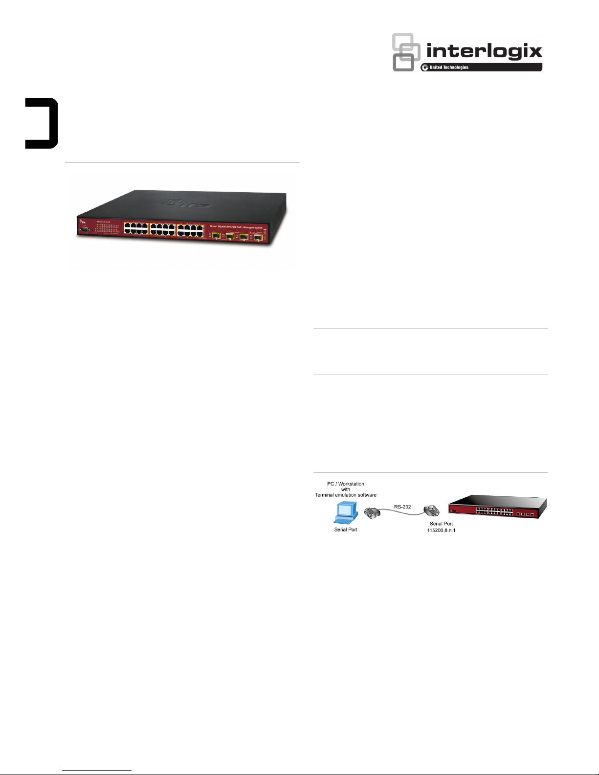
Terminal setup
To configure the system, connect a serial cable to a COM port
on a PC or notebook computer and to a serial (console) port on
the managed switch.
Figure 2: Console connectivity
A terminal program is required to make the software connected
to the managed switch. Windows' Hyper Terminal program
may be a good choice. The Hyper Terminal can be accessed
from the Start menu.
1. Click Start > Programs > Accessories > Hyper
Terminal.
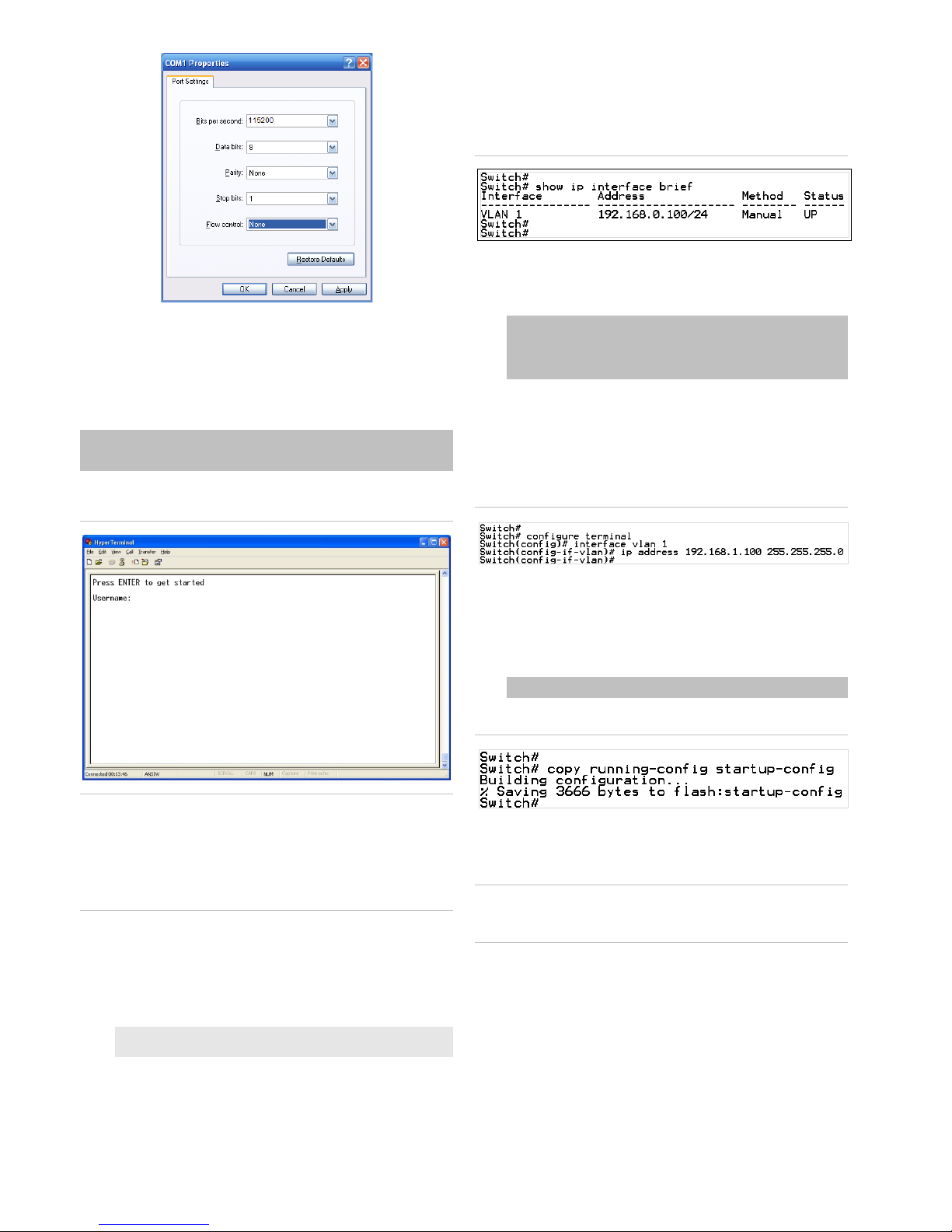
2. When the following screen appears, ensure that the COM
port is configured as shown below. Click OK when finished
with configuration.
2 / 4 P/N 1073538-EN • REV A • ISS 05SEP18
3. Log in to the console. After the terminal has been
connected to the device, power on the managed switch.
The terminal displays “running testing procedures”.
When the following dialog box in Figure 3 below appears,
type the factory default user name "admin" and password
“admin”.
User name: admin
Password: admin
Figure 3: Console login screen
Note:
1. For security purposes, change and memorize the new
password after this first setup.
2. Only commands in lowercase letters are accepted in the
console interface.
Configuring the IP address
The managed switch is shipped with the default IP address
shown below:
IP Address: 192.168.0.100
Subnet Mask: 255.255.255.0
To check the current IP address or modify a new IP address
for the managed switch, use the following procedures:
Display of the current IP Address
1. At the “#” prompt, type “show ip interface brief”.
2. The screen displays the current IP address.
Figure 4: IP information screen
Configuration of the IP address
3. At the “#” prompt, type the following command and press
Enter as shown in Figure 5.
Switch# configure terminal
Switch(config)# interface vlan 1
Switch(config-if-vlan)# ip address 192.168.1.100
255.255.255.0
The previous command would apply the following settings
for the managed switch.
IP Address: 192.168.1.100
Subnet Mask: 255.255.255.0
Figure 5: Configuring the IP address screen
4. Repeat step 1 to check if the IP address has changed.
Store the current switch configuration
5. At the “#” prompt, type the following command and press
Enter.
# copy running-config startup-config
Figure 6: Saving current configuration command screen
If the IP is successfully configured, the managed switch applies
the new IP address setting immediately. Access the web
interface of the managed switch through the new IP address.
Note: If unfamiliar with the console command or the related
parameter, type “help” in the console to obtain the Help
description.
Starting web management
The section describes how to start up the web management
function for the managed switch. Note that the managed switch
is configured through an Ethernet connection. Ensure that the
manager computer is set to the same IP subnet address.
For example, if the default IP address of the managed switch is
192.168.0.100, then the manager computer should be set to
 Loading...