


NS3702-24P-4S
User Manual
P/N 1072832 • REV 00.01 • ISS 14JUL14

r
y
Copyright © 2014 United Technologies Corporation
Interlogix is part of UTC Building & Industrial Systems,Inc. a unit of United
Technologies Corporation. All rights reserved.
Trademarks and
patents
Manufacture
Intended use
Certification
FCC compliance
The NS3702-24P-4S name and logo are trademarks of United Technologies.
Other trade names used in this document may be trademarks or registered
trademarks of the manufacturers or vendors of the respective products.
Interlogix
3211 Progress Drive, Lincolnton, NC 28092 USA
Authorized EU manufacturing representative:
UTC Climate Controls & Security B.V.,
Kelvinstraat 7, 6003 DH Weert, Netherlands
Use this product only for the purpose it was designed for; refer to the data sheet
and user documentation for details. For the latest product information, contact
your local supplier or visit us online at www.interlogix.com.
N4131
This equipment has been tested and found to comply with the limits for a Class
A digital device, pursuant to part 15 of the FCC Rules. These limits are
designed to provide reasonable protection against harmful interference when
the equipment is operated in a commercial environment. This equipment
ACMA compliance
Canada
European Union
directives
generates, uses, and can radiate radio frequency energy and, if not installed
and used in accordance with the instruction manual, may cause harmful
interference to radio communications.
You are cautioned that any changes or modifications not expressly approved b
the party responsible for compliance could void the user's authority to operate
the equipment.
Notice! This is a Class A product. In a domestic environment this product may
cause radio interference in which case the user may be required to take
adequate measures.
This Class A digital apparatus complies with Canadian ICES-003.
Cet appareil numérique de la classe A est conforme á la norme NMB-003du
Canada.
2004/108/EC (EMC Directive): Hereby, UTC Building & Industrial Systems, Inc.
declares that this device is in compliance with the essential requirements and
other relevant provisions of Directive 2004/108/EC.
Contact Information For contact information, see www.interlogix.com
www.utcfssecurityproducts.eu
.
2
or

TABLE OF CONTENTS
1. INTRODUCTION..................................................................................................................10
1.1 Packet Contents .........................................................................................................................................10
1.2 Product Description...................................................................................................................................11
1.3 How to Use This Manual............................................................................................................................14
1.4 Product Features........................................................................................................................................15
1.5 Product Specifications ..............................................................................................................................18
2. INSTALLATION ...................................................................................................................22
2.1 Hardware Description................................................................................................................................22
2.1.1 Switch Front Panel ..............................................................................................................................................22
2.1.2 LED Indications ...................................................................................................................................................23
2.1.3 Switch Rear Panel ...............................................................................................................................................25
2.2 Installing the Switch...................................................................................................................................26
2.2.1 Desktop Installation .............................................................................................................................................26
2.2.2 Rack Mounting.....................................................................................................................................................27
2.2.3 Installing the SFP Transceiver.............................................................................................................................28
3. SWITCH MANAGEMENT....................................................................................................32
3.1 Requirements..............................................................................................................................................32
3.2 Management Access Overview.................................................................................................................33
3.3 Administration Console.............................................................................................................................34
3.4 Web Management.......................................................................................................................................35
3.5 SNMP-based Network Management.........................................................................................................36
4. WEB CONFIGURATION......................................................................................................37
4.1 Main Web Page...........................................................................................................................................40
4.2 System.........................................................................................................................................................42
4.2.1 System Information..............................................................................................................................................43
3

4.2.2 IP Configuration...................................................................................................................................................44
4.2.3 IP Status ..............................................................................................................................................................46
4.2.4 Users Configuration .............................................................................................................................................47
4.2.5 Privilege Levels ...................................................................................................................................................51
4.2.6 NTP Configuration ...............................................................................................................................................53
4.2.7 Time Configuration ..............................................................................................................................................54
4.2.8 UPnP ...................................................................................................................................................................55
4.2.9 DHCP Relay ........................................................................................................................................................57
4.2.10 DHCP Relay Statistics .......................................................................................................................................59
4.2.11 CPU Load ..........................................................................................................................................................61
4.2.12 System Log........................................................................................................................................................62
4.2.13 Detailed Log ......................................................................................................................................................63
4.2.14 Remote Syslog ..................................................................................................................................................64
4.2.15 SMTP Configuration ..........................................................................................................................................66
4.2.16 Web Firmware Upgrade.....................................................................................................................................67
4.2.17 TFTP Firmware Upgrade ...................................................................................................................................68
4.2.18 Save Startup Config...........................................................................................................................................69
4.2.19 Configuration Download ....................................................................................................................................69
4.2.20 Configuration Upload.........................................................................................................................................70
4.2.21 Configuration Activate........................................................................................................................................71
4.2.22 Configuration Delete..........................................................................................................................................71
4.2.23 Image Select......................................................................................................................................................72
4.2.24 Factory Default ..................................................................................................................................................73
4.2.25 System Reboot ..................................................................................................................................................73
4.3 Simple Network Management Protocol....................................................................................................74
4.3.1 SNMP Overview ..................................................................................................................................................74
4.3.2 SNMP System Configuration ...............................................................................................................................76
4.3.3 SNMP Trap Configuration....................................................................................................................................78
4.3.4 SNMP System Information ..................................................................................................................................80
4.3.5 SNMPv3 Configuration ........................................................................................................................................81
4.3.5.1 SNMPv3 Communities ..............................................................................................................................81
4.3.5.2 SNMPv3 Users..........................................................................................................................................82
4.3.5.3 SNMPv3 Groups........................................................................................................................................84
4.3.5.4 SNMPv3 Views..........................................................................................................................................85
4.3.5.5 SNMPv3 Access........................................................................................................................................86
4.4 Port Management .......................................................................................................................................88
4

4.4.1 Port Configuration................................................................................................................................................88
4.4.2 Port Statistics Overview.......................................................................................................................................90
4.4.3 Port Statistics Detail.............................................................................................................................................91
4.4.4 SFP Module Information ......................................................................................................................................93
4.4.5 Port Mirror............................................................................................................................................................94
4.5 Link Aggregation........................................................................................................................................97
4.5.1 Static Aggregation................................................................................................................................................99
4.5.2 LACP Configuration...........................................................................................................................................101
4.5.3 LACP System Status .........................................................................................................................................104
4.5.4 LACP Port Status...............................................................................................................................................105
4.5.5 LACP Port Statistics...........................................................................................................................................106
4.6 VLAN..........................................................................................................................................................107
4.6.1 VLAN Overview .................................................................................................................................................107
4.6.2 IEEE 802.1Q VLAN ...........................................................................................................................................108
4.6.3 VLAN Port Configuration ................................................................................................................................... 111
4.6.4 VLAN Membership Status..................................................................................................................................11 8
4.6.5 VLAN Port Status...............................................................................................................................................122
4.6.6 Private VLAN .....................................................................................................................................................123
4.6.7 Port Isolation......................................................................................................................................................125
4.6.8 VLAN setting example: ......................................................................................................................................128
4.6.8.1 Two Separate 802.1Q VLANs..................................................................................................................128
4.6.8.2 VLAN Trunking between two 802.1Q aware switches .............................................................................130
4.6.8.3 Port Isolate ..............................................................................................................................................133
4.6.9 MAC-based VLAN .............................................................................................................................................136
4.6.10 MAC-based VLAN Status ................................................................................................................................137
4.6.11 Protocol-based VLAN ......................................................................................................................................138
4.6.12 Protocol-based VLAN Membership .................................................................................................................139
4.7 Spanning Tree Protocol...........................................................................................................................142
4.7.1 Theory ...............................................................................................................................................................142
4.7.2 STP System Configuration ................................................................................................................................149
4.7.3 Bridge Status .....................................................................................................................................................152
4.7.4 CIST Port Configuration.....................................................................................................................................153
4.7.5 MSTI Priorities ...................................................................................................................................................156
4.7.6 MSTI Configuration............................................................................................................................................157
4.7.7 MSTI Ports Configuration ..................................................................................................................................158
4.7.8 Port Status.........................................................................................................................................................160
5

4.7.9 Port Statistics.....................................................................................................................................................161
4.8 Multicast....................................................................................................................................................163
4.8.1 IGMP Snooping .................................................................................................................................................163
4.8.2 Profile Table.......................................................................................................................................................168
4.8.3 Address Entry ....................................................................................................................................................169
4.8.4 IGMP Snooping Configuration ...........................................................................................................................170
4.8.5 IGMP Snooping VLAN Configuration.................................................................................................................173
4.8.6 IGMP Snooping Port Group Filtering .................................................................................................................175
4.8.7 IGMP Snooping Status ......................................................................................................................................176
4.8.8 IGMP Group Information....................................................................................................................................177
4.8.9 IGMPv3 Information...........................................................................................................................................178
4.8.10 MLD Snooping Configuration...........................................................................................................................180
4.8.11 MLD Snooping VLAN Configuration.................................................................................................................181
4.8.12 MLD Snooping Port Group Filtering................................................................................................................. 183
4.8.13 MLD Snooping Status......................................................................................................................................185
4.8.14 MLD Group Information ...................................................................................................................................186
4.8.15 MLDv2 Information ..........................................................................................................................................187
4.8.16 MVR (Multicaset VLAN Registration)...............................................................................................................189
4.8.17 MVR Status......................................................................................................................................................192
4.8.18 MVR Groups Information .................................................................................................................................193
4.8.19 MVR SFM Information .....................................................................................................................................194
4.9 Quality of Service.....................................................................................................................................196
4.9.1 Understanding QoS ...........................................................................................................................................196
4.9.2 Port Policing ......................................................................................................................................................197
4.9.3 Port Classification..............................................................................................................................................198
4.9.4 Port Scheduler...................................................................................................................................................200
4.9.5 Port Shaping......................................................................................................................................................201
4.9.5.1 QoS Egress Port Schedule and Shapers ................................................................................................202
4.9.6 Port Tag Remarking ...........................................................................................................................................203
4.9.6.1 QoS Egress Port Tag Remarking.............................................................................................................205
4.9.7 Port DSCP .........................................................................................................................................................206
4.9.8 DSCP-based QoS .............................................................................................................................................208
4.9.9 DSCP Translation ..............................................................................................................................................210
4.9.10 DSCP Classification.........................................................................................................................................211
4.9.11 QoS Control List...............................................................................................................................................212
4.9.11.1 QoS Control Entry Configuration ...........................................................................................................214
6

4.9.12 QCL Status ......................................................................................................................................................216
4.9.13 Storm Control Configuration ............................................................................................................................218
4.9.14 WRED..............................................................................................................................................................220
4.9.15 QoS Statistics ..................................................................................................................................................222
4.9.16 Voice VLAN Configuration ...............................................................................................................................223
4.9.17 Voice VLAN OUI Table.....................................................................................................................................226
4.10 Access Control Lists..............................................................................................................................228
4.10.1 Access Control List Status ...............................................................................................................................228
4.10.2 Access Control List Configuration ....................................................................................................................230
4.10.3 ACE Configuration ...........................................................................................................................................232
4.10.4 ACL Ports Configuration ..................................................................................................................................243
4.10.5 ACL Rate Limiter Configuration .......................................................................................................................245
4.11 Authentication.........................................................................................................................................246
4.11.1 Understanding IEEE 802.1X Port-Based Authentication..................................................................................247
4.11.2 Authentication Configuration ............................................................................................................................250
4.11.3 Network Access Server Configuration..............................................................................................................252
4.11.4 Network Access Overview ...............................................................................................................................264
4.11.5 Network Access Statistics ................................................................................................................................265
4.11.6 RADIUS ...........................................................................................................................................................272
4.11.7 TACACS+ ........................................................................................................................................................275
4.11.8 RADIUS Overview ...........................................................................................................................................277
4.11.9 RADIUS Details ...............................................................................................................................................279
4.11.10 Windows Platform RADIUS Server Configuration..........................................................................................285
4.11.11 802.1X Client Configuration ...........................................................................................................................291
4.12 Security ...................................................................................................................................................294
4.12.1 Port Limit Control.............................................................................................................................................294
4.12.2 Access Management .......................................................................................................................................299
4.12.3 Access Management Statistics ........................................................................................................................300
4.12.4 HTTPs .............................................................................................................................................................302
4.12.5 SSH .................................................................................................................................................................302
4.12.6 Port Security Status.........................................................................................................................................303
4.12.7 Port Security Detail..........................................................................................................................................306
4.12.8 DHCP Snooping ..............................................................................................................................................307
4.12.9 Snooping Table ................................................................................................................................................309
4.12.10 IP Source Guard Configuration......................................................................................................................309
4.12.11 IP Source Guard Static Table......................................................................................................................... 311
7

4.12.12 ARP Inspection ..............................................................................................................................................312
4.12.13 ARP Inspection Static Table...........................................................................................................................314
4.13 Address Table.........................................................................................................................................315
4.13.1 MAC Table Configuration.................................................................................................................................315
4.13.2 MAC Address Table Status ..............................................................................................................................317
4.13.3 Dynamic ARP Inspection Table........................................................................................................................318
4.13.4 Dynamic IP Source Guard Table......................................................................................................................319
4.14 LLDP........................................................................................................................................................322
4.14.1 Link Layer Discovery Protocol .........................................................................................................................322
4.14.2 LLDP Configuration .........................................................................................................................................322
4.14.3 LLDP MED Configuration ................................................................................................................................325
4.14.4 LLDP-MED Neighbor.......................................................................................................................................332
4.14.5 Neighbor ..........................................................................................................................................................336
4.14.6 Port Statistics...................................................................................................................................................337
4.15 Network Diagnostics..............................................................................................................................340
4.15.1 Ping .................................................................................................................................................................341
4.15.2 IPv6 Ping .........................................................................................................................................................342
4.15.3 Remote IP Ping Test........................................................................................................................................343
4.15.4 Cable Diagnostics............................................................................................................................................344
4.16 Power over Ethernet ..............................................................................................................................346
4.16.1 Power over Ethernet Powered Device.............................................................................................................346
4.16.2 System Configuration ......................................................................................................................................347
4.16.3 Power Over Ethernet Configuration.................................................................................................................348
4.16.4 Port Sequential ................................................................................................................................................351
4.16.5 Port Configuration............................................................................................................................................352
4.16.6 PoE Status.......................................................................................................................................................354
4.16.7 PoE Schedule..................................................................................................................................................357
4.16.8 LLDP PoE Neighbours.....................................................................................................................................359
4.16.9 PoE Alive Check Configuration........................................................................................................................360
4.16.10 Port Power Consumption...............................................................................................................................363
4.17 Loop Protection......................................................................................................................................364
4.17.1 Configuration ...................................................................................................................................................364
4.17.2 Loop Protection Status.....................................................................................................................................366
4.18 RMON.......................................................................................................................................................367
8

4.18.1 RMON Alarm Configuration .............................................................................................................................367
4.18.2 RMON Alarm Status.........................................................................................................................................369
4.18.3 RMON Event Configuration .............................................................................................................................370
4.18.4 RMON Event Status.........................................................................................................................................372
4.18.5 RMON History Configuration ...........................................................................................................................373
4.18.6 RMON History Status.......................................................................................................................................374
4.18.7 RMON Statistics Configuration ........................................................................................................................375
4.18.8 RMON Statistics Status....................................................................................................................................376
5. SWITCH OPERATION.......................................................................................................378
5.1 Address Table...........................................................................................................................................378
5.2 Learning ....................................................................................................................................................378
5.3 Forwarding & Filtering.............................................................................................................................378
5.4 Store-and-Forward...................................................................................................................................378
5.5 Auto-Negotiation ......................................................................................................................................379
6. Power over Ethernet Overview........................................................................................380
7. TROUBLESHOOTING....................................................................................................... 382
APPENDIX A: Networking Connection ............................................................................... 383
A.1 PoE RJ-45 Port Pin Assignments...........................................................................................................383
A.2 Switch's Data RJ-45 Pin Assignments - 1000Mbps, 1000Base-T........................................................383
A.3 10/100Mbps, 10/100Base-TX...................................................................................................................384
APPENDIX B : GLOSSARY ..................................................................................................386
9

1. INTRODUCTION
NS3702-24P-4S - 24-Port 10/100/1000Mbps 802.3at PoE+ ports, 4-Port Shared Gigabit RJ45 and SFP ports, Managed Switch with
Hardware Layer 3 IPv4/IPv6 Static Routing, NS3702-24P-4S, comes with the multi-port Gigabit Ethernet Switch and SFP fiber optic
connectibility and robust layer 2+ features. The description of this model is shown below:
NS3702-24P-4S 24-Port 10/100/1000Mbps 802.3at PoE + 4-Port Gigabit TP / SFP Combo Managed Switch (440W)
“Managed Switch” is used as an alternative name in this user’s manual.
1.1 Packet Contents
Open the box of the Managed Switch and carefully unpack it. The box should contain the following items:
Check the contents of your package for the following parts:
The Managed Switch
x1
User’s Manual CD
Quick Installation Guide
RS-232 DB9 Male Console Cable
Rubber Feet
Rack Mount Accessory Kit
Power Cord
If any of these are missing or damaged, please contact your dealer immediately; if possible, retain the carton including the original
packing material, and use them again to repack the product in case there is a need to return it to us for repair.
x1
x1
x1
x4
x1
x1
10

1.2 Product Description
Ideal Solution for Secure IP Surveillance Construction
Particularly designed for the growing popular IP Surveillance applications, IFS Gigabit 802.3at PoE Managed Switch
NS3702-24P-4S is positioned as a Surveillance Switch with central management of remote Power control and IP camera monitoring.
The NS3702 provides built-in L2/L4 Switching engine and intelligent PoE functions along with 24 10/100/1000Base-T ports featuring
30Watts 802.3at PoE in RJ-45 copper interfaces and 4 Gigabit TP/SFP combo interfaces supporting high speed transmission of
surveillance images and videos
Perfect Integration Solution for IP PoE Camera and NVR System
Differentiated from generally IT industrial PoE Switch which usually contains 12 or 24 PoE ports, the NS3702 provides 24
802.3at PoE+ ports for catering to medium to large scale of IP Surveillance networks with lower total cost. With 48Gbps high
performance switch architecture, 440 watts PoE shared power budget offered by NS3702, the recorded video files from 24 PoE IP
cameras can be powered by NS3702, and saved in the 8 / 16 / 32-channel NVR systems or surveillance software to perform
comprehensive security monitoring. For instance, the NS3702 can combine with NVR and 16 or more PoE IP cameras as a kit for
the administrators centrally and efficiently manage the surveillance system in the local LAN and the remote site via Internet.
Centralized Power Management for Gigabit Ethernet PoE Networking
To fulfill the needs of higher power required PoE network applications with Gigabit speed transmission, NS3702 features high
performance Gigabit IEEE 802.3af PoE (Up to 15.4Watts) and IEEE 802.3at PoE+ (Up to 30Watts) shared on all ports. It perfectly
satisfies the PoE IP camera which needs high power consumption such as IR, PTZ, Speed Dome cameras or even Box type IP
cameras with built in fan and heater.
The PoE capabilities provided also help to reduce deployment costs for network devices as a result of freeing from restrictions of
power outlet locations. Power and data switching are integrated into one unit, delivered over a single cable and managed centrally. It
thus eliminates cost for additional AC wiring and reduces installation time.
Built-in Unique PoE Functions for Surveillance Management
As a managed PoE Switch for surveillance network, the NS3702 features four special PoE Management functions:
PD A LIVE Check
Schedule Power Recycle
SMTP/SNMP Trap Event Alert
PoE Schedule
11

Intelligent Powered Device Alive-Checking
The NS3702 can be configured to monitor connected PD (Powered Device) status in real-time via ping action. Once the PD stops
working and no response, the NS3702 will resume the PoE port power and bring the PD back to work. It will greatly enhance the
network reliability through the PoE port resetting the PD’s power source and reduce administrator management burden.
Schedule Power Recycle
The NS3702 allows each of the connected PoE IP cameras to reboot in a specific time each week. Therefore, it will reduce the
chance of IP camera crash resulting from buffer overflow.
SMTP/SNMP Trap Event alert
Though most NVR or camera management software offers SMTP email alert function, the NS3702 further provides event alert
function to help to diagnose the abnormal device owing to whether the network connection break, lost of PoE power or the rebooting
response by PD Alive-Checking process.
PoE Schedule for Energy Saving
Besides applied in IP Surveillance, the NS3702-24P-4S is certainly applicable to construct any PoE network including VoIP and
Wireless LAN. Under the trend of energy saving worldwide and contributes to environment protection on the earth, the NS3702 can
effectively control the power supply besides its capability of giving high watts power. The “PoE schedule” function helps you to
enable or disable PoE power feeding for each PoE port during specified time intervals and it is a powerful function to help SMB or
Enterprise save power and money.
12

Cost-Effective PoE Switch solution for IPv6 Networking
Faced with the increasingly large number of IP cameras and Wireless APs be installed and deployed in all kind of application. More
and more network equipments start to support IPv6 protocol for next generation networking. To fulfill the demand of IPv6, the
NS3702 supports both IPv4 and IPv6 management functions, it can works with original IPv4 network structure and also supports the
new IPv6 network structure. With easy and friendly management interfaces and plenty of management functions included, the
NS3702-24P-4S is the best choice for IP Surveillance and Wireless service providers to connect with IPv6 network.
Efficient Management
For efficient management, the NS3702 Managed Switch is equipped with console, WEB and SNMP management interfaces. With
the built-in Web-based management interface, the NS3702 offers an easy-to-use, platform-independent management and
configuration facility. The NS3702 supports standard Simple Network Management Protocol (SNMP) and can be managed via any
standard-based management software. For text-based management, the NS3702 can be accessed via Telnet and the console port.
Moreover, the NS3702 offers secure remote management by supporting SSH, SSL and SNMPv3 connection which encrypt the
packet content at each session.
Robust Layer 2 Features
The NS3702 can be programmed for advanced switch management functions such as dynamic Port link aggregation, Q-in-Q VLAN,
private VLAN, Multiple Spanning Tree protocol(MSTP), Layer 2 to Layer 4 QoS, bandwidth control and IGMP / MLD Snooping. The
NS3702 provides 802.1Q Tagged VLAN, and the VLAN groups allowed will be maximally up to 255. Via aggregation of supporting
ports, the NS3702 allows the operation of a high-speed trunk combining multiple ports and supports fail-over as well.
Powerful Security
The NS3702 offers comprehensive Layer 2 to Layer 3 Access Control List (ACL) for enforcing security to the edge. It can be used to
restrict network access by denying packets based on source and destination IP address, TCP/UDP ports or defined typical network
applications. Its protection mechanism also comprises of 802.1x Port-Based and MAC-Based user and device authentication. With
the private VLAN function, communication between edge ports can be prevented to ensure user privacy. The NS3702 also provides
DHCP Snooping, IP Source Guard and Dynamic ARP Inspection functions to prevent IP snooping from attack and discard ARP
packets with invalid MAC address. The network administrators can now construct highly secured corporate networks with
considerably less time and effort than before.
Flexible and Extendable Uplink Solution
The 4 mini-GBIC slots built in the NS3702 supports Dual-speed, 100Base-FX and 1000Base-SX/LX SFP (Small Form-factor
Pluggable) fiber-optic modules, that means, the administrator now can flexibly choose the suitable SFP transceiver according to the
transmission distance or the transmission speed required. The distance can be extended from 550 meters (Multi-Mode fiber) up to
above 10/50/70/120 kilometers (Single-Mode fiber or WDM fiber). They are well suited for applications within the enterprise data
centers and distributions.
13

1.3 How to Use This Manual
This User’s Manual is structured as follows:
Section 2, INSTALLATION
The section explains the functions of the Managed Switch and how to physically install the Managed Switch.
Section 3, SWITCH MANAGEMENT
The section contains the information about the software function of the Managed Switch.
Section 4, WEB CONFIGURATION
The section explains how to manage the Managed Switch by Web interface.
Section 5, SWITCH OPERATION
The chapter explains how to do the switch operation of the Managed Switch.
Section 6, POWER over ETHERNET OVERVIEW
The chapter introduces the IEEE 802.3af / 802.3at PoE standard and PoE provision of the Managed Switch.
Section 7, TROUBLESHOOTING
The chapter explains how to do troubleshooting of the Managed Switch.
Appendix A
The section contains cable information of the Managed Switch.
14

1.4 Product Features
Physical Port
24-Port 10/100/1000Base-T RJ-45 copper with IEEE 802.3at / 802.3af Power over Ethernet Injector function
4 100/1000Base-X mini-GBIC/SFP slot, shared with Port-21 to Port-24 compatible with 100Base-FX SFP
RJ45 to RS-232 DB9 console interface for basic management and setup
Power over Ethernet
■ Complies with IEEE 802.3at High Power over Ethernet End-Span PSE
■ Complies with IEEE 802.3af Power over Ethernet End-Span PSE
■ Up to 24 ports of IEEE 802.3af / 802.3at devices powered
■ Supports PoE Power up to 30.8 Watts for each PoE ports
■ Auto detects powered device (PD)
■ Circuit protection prevents power interference between ports
■ Remote power feeding up to 100 meters
■ PoE Management
Total PoE power budget control
Per port PoE function enable/disable
PoE Port Power feeding priority
Per PoE port power limitation
PD classification detection
PD alive-check
PoE schedule
PD power recycling schedule
Layer 2 Features
Prevents packet loss with back pressure (half-duplex) and IEEE 802.3x pause frame flow control (full-duplex)
High performance of Store-and-Forward architecture and runt/CRC filtering eliminates erroneous packets to optimize the
network bandwidth
Storm Control support
Broadcast / Unicast / Unknown-unicast
Supports VLAN
IEEE 802.1Q Tagged VLAN
Up to 255 VLANs groups, out of 4095 VLAN IDs
Provider Bridging (VLAN Q-in-Q) support (IEEE 802.1ad)
Private VLAN Edge (PVE)
Protocol-based VLAN
MAC-based VLAN
IP Subnet-based VLAN
Voice VLAN
Supports Spanning Tree Protocol
15

STP, IEEE 802.1D Spanning Tree Protocol
RSTP, IEEE 802.1w Rapid Spanning Tree Protocol
MSTP, IEEE 802.1s Multiple Spanning Tree Protocol, spanning tree by VLAN
BPDU Guard
Supports Link Aggregation
802.3ad Link Aggregation Control Protocol (LACP)
Cisco ether-channel (Static Trunk)
Maximum 14 trunk groups, up to 8 ports per trunk group
Up to 16Gbps bandwidth (full duplex mode)
Provides Port Mirror (many-to-1)
Port Mirroring to monitor the incoming or outgoing traffic on a particular port
Loop protection to avoid broadcast loops
Layer 3 IP Routing Features
Supports maximum 128 static routes and route summarization
Quality of Service
Ingress Shaper and Egress Rate Limit per port bandwidth control
8 priority queues on all switch ports
Traffic classification
- IEEE 802.1p CoS
- TOS / DSCP / IP Precedence of IPv4/IPv6 packets
- IP TCP/UDP port number
- Typical network application
Strict priority and Weighted Round Robin (WRR) CoS policies
Traffic-policing policies on the switch port
DSCP remarking
Multicast
Supports IGMP Snooping v1, v2 and v3
Supports MLD Snooping v1 and v2
Querier mode support
IGMP Snooping port filtering
MLD Snooping port filtering
MVR (Multicast VLAN Registration)
Security
IEEE 802.1X Port-based / MAC-based network access authentication
16

IEEE 802.1X Authentication with Guest VLAN
Built-in RADIUS client to cooperate with the RADIUS servers
RADIUS / TACACS+ users access authentication
IP-based Access Control List (ACL)
MAC-based Access Control List (ACL)
Source MAC / IP address binding
DHCP Snooping to filter distrusted DHCP messages
IP address access management to prevent unauthorized intruder
Management
Switch Management Interfaces
- Console / Telnet Command Line Interface
- Web switch management
- SNMP v1, v2c, and v3 switch management
- SSH / SSL secure access
Four RMON groups (history, statistics, alarms and events)
IPv6 Address / NTP management
Built-in Trivial File Transfer Protocol (TFTP) client
BOOTP and DHCP for IP address assignment
Firmware upload / download via HTTP / TFTP
DHCP Relay and Option 82
User Privilege levels control
NTP (Network Time Protocol)
Link Layer Discovery Protocol (LLDP)
SFP-DDM (Digital Diagnostic Monitor)
Cable Diagnostic technology provides the mechanism to detect and report potential cabling issues
ICMPv6 / ICMPv4 Remote Ping
Reset button for system reboot or reset to factory default
SMTP / Syslog / SNMP Trap remote alarm
System Log
Smart Discovery Utility for deploy management
17
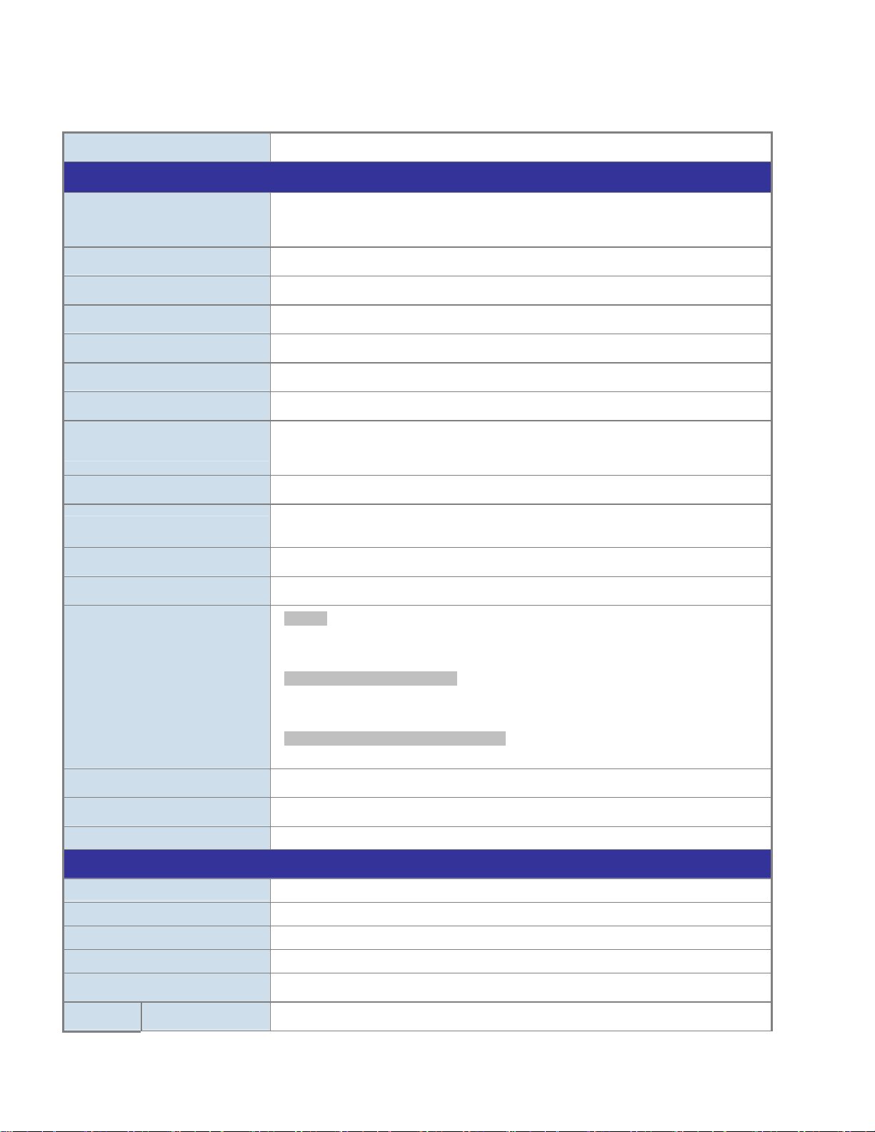
1.5 Product Specifications
Product NS3702-24P-4S
Hardware Specifications
SFP/mini-GBIC Slots
Console
Switch Architecture
Switch Fabric
Throughput
Address Table
Share Data Buffer
Flow Control
Jumbo Frame
Reset Button
Dimension (W x D x H)
Weight
LED
4 100/1000Base-X SFP interfaces, shared with Port-21 to Port-24
Compatible with 100Base-FX SFP transceiver
1 x RS-232 DB9 serial port (115200, 8, N, 1)
Store-and-Forward
48Gbps / non-blocking
35.7Mpps@64Bytes
16K entries, automatic source address learning and ageing
4M bits
IEEE 802.3x pause frame for full-duplex
Back pressure for half-duplex
9K bytes
< 5 sec: System reboot
> 5 sec: Factory Default
440 x 300 x 44.5 mm, 1U height
4750g
System:
Power (Green)
FAN1 ( Green), FAN2 (Green), FAN3 (Green), PWR (Green)
10/100/1000T RJ45 Interfaces (Port 1 to Port 24):
10/100/1000Mbps LNK/ACT (Green)
PoE In-Use (Orange)
100/1000Mbps SFP Combo Interfaces (Port 21 to Port 24):
1000Mbps (Green), LNK/ACT (Orange)
Power Requirement
Power Consumption
ESD Protection
Power over Ethernet
PoE Standard IEEE 802.3af / 802.3at PoE / PSE
PoE Power Supply Type End-span
PoE Power Output
Power Pin Assignment 1/2(+), 3/6(-)
PoE Power Budget
PoE Ability PD @ 7 watts
100~240V AC, 50/60Hz, 6A
422 watts / 1447 BTU Max.
6KV DC
Per Port 56V DC, Max. 30.8 watts
440 watts Max.
24 units
18

PD @ 15.4 watts
PD @ 30.8 watts
Layer 2 Functions
Port Configuration
Port Status
Port Mirroring
VLAN
Link Aggregation
24 units
14 units
Port disable / enable
Auto-Negotiation 10/100/1000Mbps full and half duplex mode selection
Flow Control disable / enable
Display each port’s speed duplex mode, link status, flow control status, Auto
negotiation status, trunk status
TX / RX / Both
Many-to-1 monitor
802.1Q Tagged-based VLAN, up to 256 VLAN groups
Q-in-Q tunneling
Private VLAN Edge (PVE)
MAC-based VLAN
Protocol-Based VLAN
IP Subnet-based VLAN
Voice VLAN
MVR (Multicast VLAN Registration)
GVRP
Up to 255 VLAN groups, out of 4094 VLAN IDs
IEEE 802.3ad LACP / Static Trunk
Supports 12 groups of 16-port trunk
QoS
IGMP Snooping
MLD Snooping
Access Control List
Bandwidth Control
Layer 3 Functions
IP Interfaces
Routing Table
Traffic classification based, Strict priority and WRR
8-Level priority for switching
- Port Number
- 802.1p priority
- 802.1Q VLAN tag
- DSCP/TOS field in IP Packet
IGMP (v1/v2/v3) Snooping, up to 255 multicast Groups
IGMP Querier mode support
MLD (v1/v2) Snooping, up to 255 multicast Groups
MLD Querier mode support
IP-Based ACL / MAC-Based ACL
Up to 256 entries
Per port bandwidth control
Ingress: 100Kbps~1000Mbps
Egress: 100Kbps~1000Mbps
Max. 128 VLAN interfaces
Max. 32 routing entries
19

Routing Protocols
Management Functions
Basic Management Interfaces
Secure Management Interfaces
SNMP MIBs
IPv4 software Static Routing
IPv6 software Static Routing
Console, Telnet, Web Browser, SNMP v1, v2c
SSH, SSL, SNMP v3
RFC-1213 MIB-II
RFC-1493 Bridge MIB
RFC-1643 Ethernet MIB
RFC-2863 Interface MIB
RFC-2665 Ether-Like MIB
RFC-2819 RMON MIB (Group 1, 2, 3 and 9)
RFC-2737 Entity MIB
RFC-2618 RADIUS Client MIB
RFC-2863 IF-MIB
RFC-2933 IGMP-STD-MIB
RFC-3411 SNMP-Frameworks-MIB
RFC-4292 IP Forward MIB
RFC-4293 IP MIB
RFC-4836 MAU-MIB
IEEE 802.1X PAE
LLDP
Standards Conformance
Regulation Compliance
Standards Compliance
FCC Part 15 Class A, CE
IEEE 802.3 10Base-T
IEEE 802.3u 100Base-TX/100Base-FX
IEEE 802.3z Gigabit SX/LX
IEEE 802.3ab Gigabit 1000T
IEEE 802.3x Flow Control and Back pressure
IEEE 802.3ad Port trunk with LACP
IEEE 802.1D Spanning tree protocol
IEEE 802.1w Rapid spanning tree protocol
IEEE 802.1s Multiple spanning tree protocol
IEEE 802.1p Class of service
IEEE 802.1Q VLAN Tagging
IEEE 802.1x Port Authentication Network Control
IEEE 802.1ab LLDP
IEEE 802.3af Power over Ethernet
IEEE 802.3at Power over Ethernet PLUS
RFC 768 UDP
RFC 793 TFTP
RFC 791 IP
RFC 792 ICMP
RFC 2068 HTTP
RFC 1112 IGMP version 1
RFC 2236 IGMP version 2
20

Environment
RFC 3376 IGMP version 3
RFC 2710 MLD version 1
RFC 3810 MLD version 2
Operating
Storage
Temperature: 0 ~ 50 degrees C
Relative Humidity: 20 ~ 95% (non-condensing)
Temperature: -20 ~ 70 degrees C
Relative Humidity: 20 ~ 95% (non-condensing)
21

2. INSTALLATION
This section describes the hardware features and installation of the Managed Switch on the desktop or rack mount. For easier
management and control of the Managed Switch, familiarize yourself with its display indicators, and ports. Front panel illustrations in
this chapter display the unit LED indicators. Before connecting any network device to the Managed Switch, please read this chapter
completely.
2.1 Hardware Description
2.1.1 Switch Front Panel
The front panel provides a simple interface monitoring the Managed Switch. Figure 2-1-1 shows the front panel of the Managed
Switch.
NS3702-24P-4S Front Panel
Figure 2-1-1: Front Panels of NS3702-24P-4S
■ Gigabit TP interface
10/100/1000Base-T Copper, RJ-45 Twist-Pair: Up to 100 meters.
■ SFP slot
100/1000Base-X mini-GBIC slot, SFP (Small Factor Pluggable) transceiver module: From 550 meters to 2km (multi-mode fiber),
up to above 10/20/30/70 kilometers (single-mode fiber).
22

■ Console Port
The console port is a RJ-45 port connector. It is an interface for connecting a terminal directly. Through the console port, it
provides rich diagnostic information including IP Address setting, factory reset, port management, link status and system setting.
Users can use the attached DB9 console cable in the package and connect to the console port on the device. After the
connection, users can run any terminal emulation program (Hyper Terminal, ProComm Plus, Telix, Winterm and so on) to enter
the startup screen of the device.
■ Reset button
At the right of the front panel, the reset button is designed for rebooting the Managed Switch without turning off and on the
power. The following is the summary table of reset button functions:
Reset Button Pressed and Released Function
< 5 sec: System Reboot Reboot the Managed Switch.
Reset the Managed Switch to Factory Default configuration.
The Managed Switch will then reboot and load the default
settings as shown below:
> 5 sec: Factory Default
。 Default Username: admin
。 Default Password: admin
。 Default IP address: 192.168.0.100
。 Subnet mask: 255.255.255.0
。 Default Gateway: 192.168.0.254
2.1.2 LED Indications
The front panel LEDs indicate instant status of power and system status, fan status, port links / PoE in-use and data activity; they
help monitor and troubleshoot when needed. Figure 2-1-2 shows the LED indications of the Managed Switch.
NS3702-24P-4S LED Indication
Figure 2-1-2:
NS3702-24P-4S LED at Front Panel
23

NS3702-24P-4S LED Indication T able
LED definition
System
LED Color Function
PWR Green Lights to indicate this switch has powered.
Alert
LED Color Function
FAN1 Green Lights to indicate FAN1 failure.
FAN2 Green Lights to indicate FAN2 failure.
FAN3 Green Lights to indicate FAN3 failure.
PWR Green Lights to indicate Power failure.
Per 10/100/1000Mbps RJ45 Port (Port-1 to Port-24)
LED Color Function
LNK/ACT Green
PoE In-Use Orange
Per 100/1000Base-X SFP Interface (Port-23 to Port-24)
LED Color Function
1000 LNK/ACT Green
100 LNK/ACT Orange
Lights to indicate the port link is established at 10/100/1000Mbps successfully.
Blinks to indicate the switch is sending or receiving data over that port actively.
Lights to indicate the port is providing 56V DC in-line power.
Lights off to indicate the connected device is not a PoE Powered Device (PD).
Lights. To indicate the port is successfully established at 1000Mbps.
Blink: To indicate that the Switch is actively sending or receiving data over that port.
Lights: To indicate the port is successfully established at 100Mbps.
Blink: To indicate that the Switch is actively sending or receiving data over that port.
24

2.1.3 Switch Rear Panel
The rear panel of the Managed Switch indicates an AC inlet power socket, which accepts input power from 100 to 240V AC,
50-60Hz. Figure 2-1-3 shows the rear panel of the Managed Switch.
NS3702-24P-4S Rear Panel
Figure 2-1-3: Rear Panel of NS3702-24P-4S
■ AC Power Receptacle
For compatibility with electric service in most areas of the world, the Managed Switch’s power supply automatically adjusts
line power in the range of 100-240V AC and 50/60 Hz.
Plug the female end of the power cord firmly into the receptalbe on the rear panel of the Managed Switch. Plug the other end of
the power cord into an electric service outlet and the power will be ready.
The device is a power-required device, which means it will not work till it is powered. If your networks
should be active all the time, please consider using UPS (Uninterrupted Power Supply) for your device.
Power Notice:
It will prevent you from network data loss or network downtime. In some areas, installing a surge
suppression device may also help to protect your Managed Switch from being damaged by unregulated
surge or current to the Switch or the power adapter.
25
2.2 Installing the Switch
This section describes how to install your Managed Switch and make connections to the Managed Switch. Please read the following
topics and perform the procedures in the order being presented. To install your Managed Switch on a desktop or shelf, simply
complete the following steps.
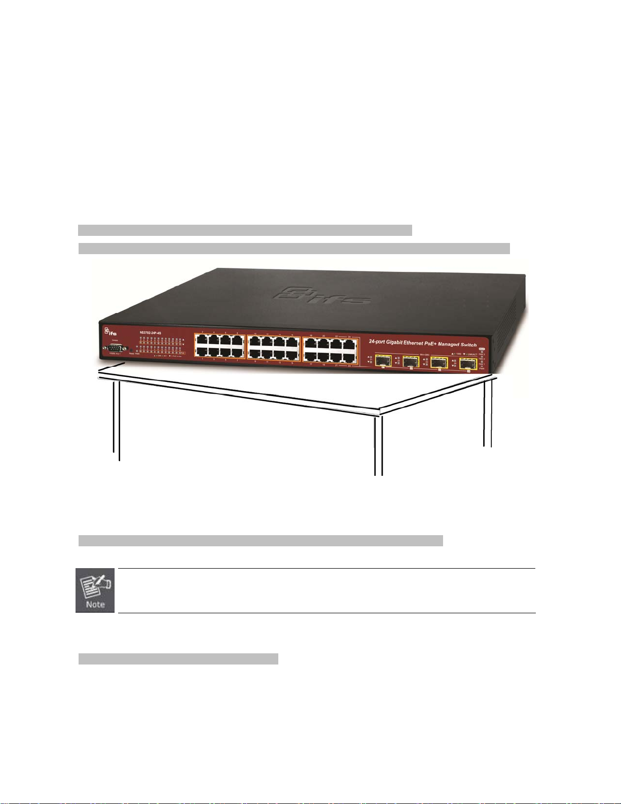
2.2.1 Desktop Installation
To install the Managed Switch on desktop or shelf, please follow these steps:
Step 1: Attach the rubber feet to the recessed areas on the bottom of the Managed Switch.
Step 2: Place the Managed Switch on the desktop or the shelf near an AC power source, as shown in Figure 2-2-1.
Figure 2-2-1: Place the Managed Switch on the Desktop
Step 3: Keep enough ventilation space between the Managed Switch and the surrounding objects.
When choosing a location, please keep in mind the environmental restrictions discussed in Chapter 1,
Section 4, and specifications.
Step 4: Connect the Managed Switch to network devices.
Connect one end of a standard network cable to the 10/100/1000 RJ-45 ports on the front of the Managed Switch.
Connect the other end of the cable to the network devices such as printer server, workstation or router.
26
Connection to the Managed Switch requires UTP Category 5e network cabling with RJ-45 tips. For
more information, please see the Cabling Specification in Appendix A.
Step 5: Supply power to the Managed Switch.
Connect one end of the power cable to the Managed Switch.
Connect the power plug of the power cable to a standard wall outlet.
When the Managed Switch receives power, the Power LED should remain solid Green.
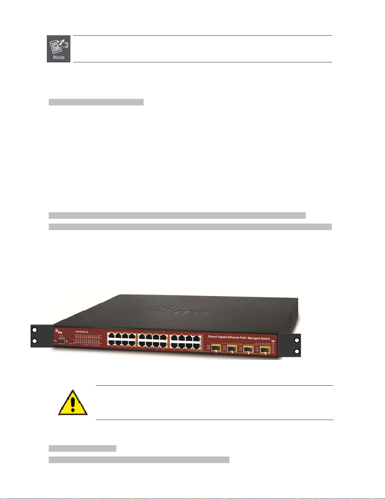
2.2.2 Rack Mounting
To install the Managed Switch in a 19-inch standard rack, please follow the instructions described below.
Step 1: Place the Managed Switch on a hard flat surface, with the front panel positioned towards the front side.
Step 2: Attach the rack-mount bracket to each side of the Managed Switch with supplied screws attached to the package.
Figure 2-2-2 shows how to attach brackets to one side of the Managed Switch.
Figure 2-2-2: Attach Brackets to the Managed Switch.
You must use the screws supplied with the mounting brackets. Damage caused to the parts by
using incorrect screws would invalidate the warranty.
Step 3: Secure the brackets tightly.
Step 4: Follow the same steps to attach the second bracket to the opposite side.
27

Step 5: After the brackets are attached to the Managed Switch, use suitable screws to securely attach the brackets to the rack, as
shown in Figure 2-2-3.
Figure 2-2-3: Mounting Managed Switch in a Rack
Step 6: Proceed with Steps 4 and 5 of session 2.2.1 Desktop Installation to connect the network cabling and supply power to the
Managed Switch.
2.2.3 Installing the SFP Transceiver
The sections describe how to insert an SFP transceiver into an SFP slot. The SFP transceivers are hot-pluggable and
hot-swappable. You can plug in and out the transceiver to/from any SFP port without having to power down the Managed Switch, as
the Figure 2-2-4 shows..
Figure 2-2-4: Plug-in the SFP Transceiver
28
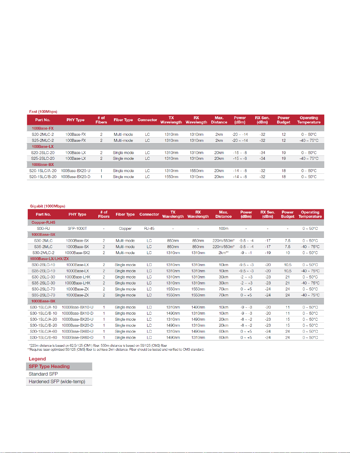
Approved IFS SFP Transceivers
NS3702 Managed Switch supports both single mode and multi-mode SFP transceiver. The following list of approved
Fast Ethernet Transceiver (100Base-X SFP)
Gigabit Ethernet Transceiver (1000Base-X SFP)
29

1. It is recommended to use IFS SFPs on the Managed Switch. If you insert an SFP transceiver that is
not supported, the Managed Switch will not recognize it.
2. Port 21 to Port 24 are a shared SFP slot that supports the Gigabit and Fast Ethernet SFP
transceiver.
1. Before we connect the NS3702 to the other network device, we have to make sure both sides of the SFP transceivers are with
the same media type, for example: 1000Base-SX to 1000Base-SX, 1000Bas-LX to 1000Base-LX.
2. Check whether the fiber-optic cable type matches with the SFP transceiver requirement.
To connect to 1000Base-SX SFP transceiver, please use the multi-mode fiber cable with one side being the male duplex
LC connector type.
To connect to 1000Base-LX SFP transceiver, please use the single-mode fiber cable with one side being the male duplex
LC connector type.
Conn ect the Fiber Cable
1. Insert the duplex LC connector into the SFP/SFP+ transceiver.
2. Connect the other end of the cable to a device with SFP/SFP+ transceiver installed.
3. Check the LNK/ACT LED of the SFP/SFP+ slot on the front of the Managed Switch. Ensure that the SFP/SFP+ transceiver is
operating correctly.
4. Check the Link mode of the SFP/SFP+ port if the link fails. To function with some fiber-NICs or Media Converters, user has to
set the port Link mode to “1000 Force” or “100 Force”.
Remove the Transceiver Module
1. Make sure there is no network activity anymore.
2. Remove the Fiber-Optic Cable gently.
3. Lift up the lever of the SFP module and turn it to a horizontal position.
4. Pull out the module gently through the lever.
30
 Loading...