

Interlogix NS3601-24P-4S-R User Manual

IFS NS3601-24P/4S
IFS GE-DSSG-244
IFS GE-DSSG-244-POE
User Manual
P/N 1072570 • REV 00.06 • ISS 10SEP12

Copyright © 2012 UTC Fire & Security. All rights reserved.
This document may not be copied in whole or in part or otherwise reproduced without
prior written consent from UTC Fire & Security, except where specifically permitted
under US and international copyright law.
Disclaimer The information in this document is subject to change without notice. UTC Fire &
Trademarks and patents
Intended use Use this product only for the purpose it was designed for; refer to the data sheet and
Manufacturer UTC Fire & Security Americas Corporation, Inc.
Certification
FCC compliance This equipment has been tested and found to comply with the limits for a Class A
ACMA compliance Notice! This is a Class A product. In a domestic environment this product may cause
Canada This Class A digital apparatus complies with Canadian ICES-003.
European Union directives 2004/108/EC (EMC Directive): Hereby, UTC Fire & Security declares that this device
Contact information
Contact support
Security assumes no responsibility for inaccuracies or omissions and specifically
disclaims any liabilities, losses, or risks, personal or otherwise, incurred as a
consequence, directly or indirectly, of the use or application of any of the contents of
this document. For the latest documentation, contact your local supplier or visit us
online at www.interlogix.com.
This publication may contain examples of screen captures and reports used in daily
operations. Examples may include fictitious names of individuals and companies. Any
similarity to names and addresses of actual businesses or persons is entirely
coincidental.
The Interlogix name and logo are trademarks of UTC Fire & Security.
The IFS name and logo are trademarks of UTC Fire & Security.
Other trade names used in this document may be trademarks or registered
trademarks of the manufacturers or vendors of the respective products.
user documentation for details. For the latest product information, contact your local
supplier or visit us online at www.interlogix.com.
2955 Red Hill Avenue
Costa Mesa, CA 92626-5923, USA
EU authorized manufacturing representative:
UTC Fire & Security B.V., Kelvinstraat 7,
6003 DH Weert, The Netherlands
N4131
digital device, pursuant to part 15 of the FCC Rules. These limits are designed to
provide reasonable protection against harmful interference when the equipment is
operated in a commercial environment. This equipment generates, uses, and can
radiate radio frequency energy and, if not installed and used in accordance with the
instruction manual, may cause harmful interference to radio communications.
You are cautioned that any changes or modifications not expressly approved by the
party responsible for compliance could void the user's authority to operate the
equipment.
radio interference in which case the user may be required to take adequate
measures.
Cet appareil numérique de la classe A est conforme á la norme NMB-003du Canada.
is in compliance with the essential requirements and other relevant provisions of
Directive 2004/108/EC.
2002/96/EC (WEEE directive): Products marked with this symbol cannot be
disposed of as unsorted municipal waste in the European Union. For proper recycling,
return this product to your local supplier upon the purchase of equivalent new
equipment, or dispose of it at designated collection points. For more information see:
www.recyclethis.info.
For contact information see our Web site:
www.interlogix.com/customer support
www.interlogix.com.

IFS NS3601-24P/4S GE-DSSG-244 and 244-POE User Manual
TABLE OF CONTENTS
5IFS NS3601-24P/4S IFS GE-DSSG-244 IFS GE-DSSG-244-POE USER MANUAL1
51. INTRODUCTION.......................................................................................................... 7
51.1 Packet Contents.................................................................................................................................. 7
51.2 Product Description............................................................................................................................9
51.3 How to Use This Manual...................................................................................................................11
51.4 Product Features............................................................................................................................... 12
51.5 Product Specification .......................................................................................................................14
52. INSTALLATION .........................................................................................................18
52.1 Hardware Description....................................................................................................................... 18
52.1.1 Switch Front Panel..................................................................................................................... 18
52.1.2 LED Indications.......................................................................................................................... 20
52.1.3 Switch Rear Panel ..................................................................................................................... 22
52.2 Install the Switch...............................................................................................................................23
52.2.1 Desktop Installation ................................................................................................................... 23
52.2.2 Rack Mounting........................................................................................................................... 25
52.2.3 Installing the SFP transceiver .................................................................................................... 26
52.3 Stack Installation............................................................................................................................... 28
52.3.1 Connecting Stacking cable ........................................................................................................ 29
52.3.2 Management Stacking ............................................................................................................... 30
53. SWITCH MANAGEMENT .......................................................................................... 32
53.1 Requirements ....................................................................................................................................32
53.2 Management Access Overview........................................................................................................ 33
53.3 Administration Console.................................................................................................................... 33
53.5 SNMP-Based Network Management................................................................................................ 35
54. WEB CONFIGURATION............................................................................................ 37
54.1 Main Web Page..................................................................................................................................40
54.2 System................................................................................................................................................ 42
54.2.1 System Information.................................................................................................................... 43
54.2.2 IP Configuration ......................................................................................................................... 44
54.2.3 IPv6 Configuration ..................................................................................................................... 45
54.2.4 Users Configuration ................................................................................................................... 46
54.2.5 Users Privilege Levels ............................................................................................................... 49
54.2.6 NTP Configuration ..................................................................................................................... 51
54.2.7 UPnP Configuration ................................................................................................................... 51
1

IFS NS3601-24P/4S GE-DSSG-244 and 244-POE User Manual
54.2.8 DHCP Relay............................................................................................................................... 53
54.2.9 DHCP Relay Statistics ............................................................................................................... 55
54.2.10 CPU Load ................................................................................................................................ 56
54.2.11 System Log .............................................................................................................................. 57
54.2.12 Detailed Log............................................................................................................................. 58
54.2.13 Remote Syslog......................................................................................................................... 58
54.2.14 SMTP Configure ...................................................................................................................... 60
54.2.15 Web Firmware Upgrade........................................................................................................... 61
54.2.16 TFTP Firmware Upgrade ......................................................................................................... 62
54.2.17 Configuration Backup .............................................................................................................. 62
54.2.18 Configuration Upload ............................................................................................................... 64
54.2.19 Factory Default......................................................................................................................... 66
54.2.20 System Reboot ........................................................................................................................ 67
64.3 Simple Network Management Protocol........................................................................................... 67
64.3.1 SNMP Overview......................................................................................................................... 67
64.3.2 SNMP System Configuration ..................................................................................................... 68
64.3.3 SNMP System Information Configuration.................................................................................. 69
64.3.4 SNMP Trap Configuration.......................................................................................................... 69
64.3.5 SNMPv3 Configuration .............................................................................................................. 71
64.4 Port Management .............................................................................................................................. 75
64.4.1 Port Configuration...................................................................................................................... 75
64.4.2 Port Statistics Overview............................................................................................................. 77
64.4.3 Port Statistics Detail................................................................................................................... 79
64.4.4 SFP Module Information ............................................................................................................ 80
64.4.5 Port Mirroring Configuration....................................................................................................... 82
64.5 Link Aggregation............................................................................................................................... 84
64.5.1 Static Aggregation Configuration ............................................................................................... 86
64.5.2 LACP Configuration ................................................................................................................... 87
64.5.3 LACP System Status ................................................................................................................. 89
64.5.4 LACP Port Status....................................................................................................................... 89
64.5.5 LACP Port Statistics .................................................................................................................. 91
64.6 VLAN...................................................................................................................................................92
64.6.1 VLAN Overview.......................................................................................................................... 92
64.6.2 IEEE 802.1Q VLAN ................................................................................................................... 92
64.6.3 VLAN Basic Information............................................................................................................. 94
64.6.4 VLAN Port Configuration ........................................................................................................... 95
64.6.5 VLAN Membership Configuration .............................................................................................. 99
64.6.6 VLAN Membership Status for User Static ............................................................................... 100
64.6.7 VLAN Port Status for User Static............................................................................................. 101
2

IFS NS3601-24P/4S GE-DSSG-244 and 244-POE User Manual
64.6.8 Port Isolation Configuration ..................................................................................................... 102
64.6.9 Private VLAN Membership Configuration................................................................................ 105
64.6.10 VLAN setting example: .......................................................................................................... 106
64.7 Spanning Tree Protocol..................................................................................................................113
64.7.1 Theory...................................................................................................................................... 113
64.7.2 STP Bridge Configuration ........................................................................................................ 118
64.7.3 Bridge Status ........................................................................................................................... 119
64.7.4 CIST Port Configuration........................................................................................................... 120
64.7.5 MSTI Priorities ......................................................................................................................... 123
64.7.6 MSTI Configuration.................................................................................................................. 124
64.7.7 MSTI Ports Configuration ........................................................................................................ 125
64.7.8 Port Status ............................................................................................................................... 127
64.7.9 Port Statistics ........................................................................................................................... 128
64.8 Multicast........................................................................................................................................... 129
64.8.1 IGMP Snooping........................................................................................................................ 129
64.8.2 IGMP Snooping Configuration................................................................................................. 133
64.8.3 IGMP Port Related Configuration ............................................................................................ 133
64.8.4 VLAN Configuration ................................................................................................................. 135
64.8.5 Port Group Filtering ................................................................................................................. 136
64.8.6 IGMP Snooping Status ............................................................................................................ 137
64.8.7 MVR Configuration .................................................................................................................. 139
64.8.8 MVR Status.............................................................................................................................. 141
64.9 Quality of Service............................................................................................................................142
64.9.1 Understand QOS ..................................................................................................................... 142
74.9.2 QCL Configuration Wizard....................................................................................................... 142
74.9.3 QoS Control List Configuration ................................................................................................ 149
74.9.4 Port QoS Configuration............................................................................................................ 151
74.9.5 Bandwidth Control ................................................................................................................... 153
74.9.6 Storm Control Configuration .................................................................................................... 155
74.9.7 QoS Statistics .......................................................................................................................... 155
74.9.8 DSCP Remarking..................................................................................................................... 157
74.9.9 Voice VLAN Configuration ....................................................................................................... 158
74.9.10 Voice VLAN OUI Table .......................................................................................................... 161
74.10 Access Control Lists..................................................................................................................... 161
74.10.1 Access Control List Status..................................................................................................... 162
74.10.2 Access Control List Configuration.......................................................................................... 163
74.10.3 ACE Configuration ................................................................................................................. 164
74.10.4 ACL Ports Configuration ........................................................................................................ 169
74.10.5 ACL Rate Limiter Configuration............................................................................................. 171
3

IFS NS3601-24P/4S GE-DSSG-244 and 244-POE User Manual
74.11.1 Understanding IEEE 802.1X Port-Based Authentication....................................................... 173
74.11.2 Authentication Configuration.................................................................................................. 175
74.11.3 Network Access Server Configuration................................................................................... 176
74.11.4 Network Access Overview ..................................................................................................... 184
74.11.5 Network Access Statistics...................................................................................................... 185
74.11.6 Authentication Server Configuration...................................................................................... 190
74.11.7 RADIUS Overview ................................................................................................................. 192
74.11.8 RADIUS Details ..................................................................................................................... 194
74.11.9 Windows Platform RADIUS Server Configuration ................................................................. 198
74.11.10 802.1X Client Configuration................................................................................................. 203
74.12 Security ..........................................................................................................................................205
74.12.1 Port Limit Control ................................................................................................................... 205
74.12.2 Access Management ............................................................................................................. 208
74.12.3 Access Management Statistics.............................................................................................. 209
74.12.4 HTTPs.................................................................................................................................... 210
74.12.5 SSH........................................................................................................................................ 210
74.12.6 Port Security Status ............................................................................................................... 211
74.12.7 Port Security Detail ................................................................................................................ 213
74.12.8 DHCP Snooping .................................................................................................................... 213
74.12.9 DHCP Snooping Statistics ..................................................................................................... 215
74.12.10 IP Source Guard Configuration............................................................................................ 217
74.12.11 IP Source Guard Static Table .............................................................................................. 218
74.12.12 ARP Inspection .................................................................................................................... 219
74.12.13 ARP Inspection Static Table ................................................................................................ 220
74.13 Address Table................................................................................................................................ 221
74.13.1 MAC Address Table Configuration ........................................................................................ 221
74.13.2 Static MAC Table Configuration ............................................................................................ 221
74.13.3 MAC Address Table Status ................................................................................................... 223
74.13.4 MAC Table Learning.............................................................................................................. 224
74.13.5 Dynamic ARP Inspection Table ............................................................................................. 225
74.13.6 Dynamic IP Source Guard Table........................................................................................... 226
74.14 LLDP............................................................................................................................................... 227
74.14.1 Link Layer Discovery Protocol ............................................................................................... 227
74.14.2 LLDP Configuration ............................................................................................................... 227
74.14.3 LLDPMED Configuration ....................................................................................................... 229
84.14.4 LLDP-MED Neighbor ............................................................................................................. 234
84.14.5 Neighbor ................................................................................................................................ 236
84.14.6 Port Statistics ......................................................................................................................... 237
84.15 Network Diagnostics.....................................................................................................................239
4

IFS NS3601-24P/4S GE-DSSG-244 and 244-POE User Manual
84.15.1 Ping........................................................................................................................................ 239
84.15.2 IPv6 Ping................................................................................................................................ 240
84.15.3 Remote IP Ping Test.............................................................................................................. 241
84.15.4 Cable Diagnostics.................................................................................................................. 242
84.16 Power over Ethernet (GE-DSSG-244-POE / NS3601-24P/4S).................................................... 243
84.16.1 Power over Ethernet Powered Device................................................................................... 244
84.16.2 Power Configuration .............................................................................................................. 244
84.16.3 Port Configuration.................................................................................................................. 246
84.16.4 PoE Status ............................................................................................................................. 248
84.16.5 PoE Schedule ........................................................................................................................ 250
84.16.6 LLDP Neighbor Power Over Ethernet ................................................................................... 251
84.17.1 Stack ...................................................................................................................................... 253
84.17.2 Stack Configuration ............................................................................................................... 255
84.17.3 Stack Information................................................................................................................... 257
84.17.4 Stack Port State Overview..................................................................................................... 258
84.17.5 Stack Example....................................................................................................................... 259
85. COMMAND LINE INTERFACE................................................................................ 262
85.1 Accessing the CLI........................................................................................................................... 262
85.2 Telnet Login..................................................................................................................................... 264
86. COMMAND LINE MODE.......................................................................................... 265
86.1 System Command........................................................................................................................... 266
86.2 Stack................................................................................................................................................. 269
86.3 IP Command.....................................................................................................................................271
86.4 Port Management Command..........................................................................................................276
86.5 MAC Address Table Command...................................................................................................... 280
86.6 VLAN Configuration Command ..................................................................................................... 284
86.7 Private VLAN Configuration Command........................................................................................ 289
86.8 Security Command.......................................................................................................................... 291
86.9 Spanning Tree Protocol Command............................................................................................... 335
86.10 Multicast Configuration Command .............................................................................................344
86.11 Link Aggregation Command........................................................................................................ 348
86.12 Link Aggregation Control Protocol Command........................................................................... 349
86.13 LLDP Command ............................................................................................................................352
86.14 LLDPMED Command ....................................................................................................................355
86.15 Power over Ethernet Command................................................................................................... 359
86.16 Quality of Service Command ....................................................................................................... 362
86.17 Mirror Command ...........................................................................................................................368
86.18 Configuration Command.............................................................................................................. 369
5

IFS NS3601-24P/4S GE-DSSG-244 and 244-POE User Manual
86.19 Firmware Command...................................................................................................................... 370
86.20 UPnP Command ............................................................................................................................ 370
86.21 MVR Command.............................................................................................................................. 371
86.22 Voice VLAN Command .................................................................................................................374
86.23 SMTP Command............................................................................................................................ 378
86.24 Show Command ............................................................................................................................ 381
87. SWITCH OPERATION.............................................................................................384
87.1 Address Table.................................................................................................................................. 384
97.2 Learning ...........................................................................................................................................384
97.3 Forwarding & Filtering.................................................................................................................... 384
97.4 Store-and-Forward.......................................................................................................................... 384
97.5 Auto-Negotiation............................................................................................................................. 384
98. POWER OVER ETHERNET OVERVIEW ................................................................ 386
9What is PoE?..........................................................................................................................................386
9The PoE Provision Process.................................................................................................................. 387
9Stages of powering up a PoE link..................................................................................................... 388
9Line Detection ................................................................................................................................... 388
9Classification..................................................................................................................................... 388
9Start-up ............................................................................................................................................. 388
9Operation .......................................................................................................................................... 388
9Power Disconnection Scenarios ....................................................................................................... 388
99. TROUBLE SHOOTING............................................................................................390
9APPENDEX A..............................................................................................................391
9A.1 Switch's RJ-45 Pin Assignments.................................................................................................. 391
9A.2 10/100Mbps, 10/100Base-TX.......................................................................................................... 391
9APPENDEX B : GLOSSARY....................................................................................... 393
9APPENDIX C: LOCAL USER PRIVILEGE LEVEL TABLE......................................... 406
6

IFS NS3601-24P/4S GE-DSSG-244 and 244-POE User Manual
1. INTRODUCTION
The IFS Layer 2 Managed Gigabit Switch series NS3601-24P/4S, GE-DSSG-244, and GE-DSSG-244-POE are 24-port Gigabit
Ethernet Switches with SFP fiber ports and robust layer 2 features. The description of these models is shown below:
GE-DSSG-244
NS3601-24P/4S 24-Port 10/100/1000Base-T PoE Managed Stackable Switch / 380W / IEEE 802.3af
GE-DSSG-244-POE 24-Port 100/1000Base- T PoE Managed Stackable Switch / 220W / IEEE 802.3af
Terms of “Managed Switch” refers to the switches listed above.
1.1 Packet Contents
Open the box of the Managed Switch and carefully unpack it. The box should contain the following items:
Check the contents of your package for following parts:
; The Managed Switch
24-Port 100/1000Base-X with 8 Shared TP Managed Stackable Fiber Switch
x1
; User’s manual CD
; Quick installation guide
; 19” Rack mount accessory kit
; Power cord
; Rubber feet
; RS-232 DB9 male Console cable
; CB-STX50 – 50cm stack cable
If any of these are missing or damaged, please contact your distributor or IFS sales rep immediately, if possible, retain the original
carton and packaging material in case you need to return the product for repair/replacement.
x1
x1
x1
x1
X4
x1
x1
7


IFS NS3601-24P/4S GE-DSSG-244 and 244-POE User Manual
1.2 Product Description
Cost-effective IPv6 Managed Gigabit Switch solution for SMB
Nowadays, lots of electronic products or mobile devices can browse the Internet, which means the need of IP Address increases.
However, the current IPv4 network infrastructure is not capable enough to provide IP Address to each single users/Clients. The
situation forces the ISP to build up the IPv6 (Internet Protocol version 6) network infrastructure speedily. To fulfill the demand,
IFS releases the IPv6 management Gigabit Ethernet Switch, IFS- series Managed Switch. It supports both IPv4 and IPv6
management functions. It can work with original network structure (IPv4) and also support the new network structure (IPv6) in the
future. With easy and friendly management interfaces and plenty of management functions included, the IFS- series Managed
Switch is the best choice for ISP to build the IPv6 FTTx edge service and for SMB to connect with IPv6 network.
High-Performance / Cost-effective / Telecom class Gigabit solution for Enterprise backbone and Data Center Networking
The IFS Managed Switch is a L2/L4 Managed Gigabit Switch. Since Gigabit network interface had become the basic equipment
and requirement of Enterprise and Network Servers, with 48Gbps switching fabric, the Managed Switch can handle extremely
large amounts of data in a secure topology linking to a backbone or high capacity servers. The powerful QoS and Network
Security features make it to meets the needs of effective data traffic control for both Campus and Enterprise, such VoIP, video
streaming and multicast application.
High Performance
The Managed Switch provides 24 10/100/1000Mbps (or 100/1000Mbps for GE-DSSG-244 fiber switch)
with 4 shared Gigabit SFP slots. It has a high performance switch architecture that is capable of providing non-blocking switch
fabric and wire-speed throughput as high as 48Gbps, which greatly simplifies the tasks of upgrading the LAN for catering to
increase bandwidth demands.
Robust Layer 2 Features
The Managed Switch can be programmed for basic switch management functions such as port speed configuration, Port
aggregation, VLAN, Spanning Tree protocol, QoS, bandwidth control and IGMP Snooping. The Managed Switch provides 802.1Q
Tagged VLAN, Q-in-Q VLAN trunning and private VLAN, the VLAN groups allowed on the Managed Switch will be maximally up to
255. Via supporting port aggregation, the Managed Switch allows the operation of a high-speed trunk combining multiple ports, up
to eight groups of maximum to 8-ports for trunking, and it supports fail-over as well.
Excellent Traffic Control
The Managed Switch is equipped with powerful traffic management and QoS features to enhance services offered by telecoms.
The functionality includes QoS features such as wire-speed Layer 4 traffic classifiers and bandwidth limiting that are particular
useful for multi-tenant unit, multi business unit, Telco, or Network Service Provide applications. It also empowers the enterprises
to take full advantages of the limited network resources and guarantees the best performance at VoIP and Video conferencing
transmission.
Gigabit Ethernet ports
9
Efficient Management
For efficient management, the series of Managed Switch is equipped with console, WEB and SNMP management interfaces. With
its built-in Web-based management, it offers an easy-to-use, platform-independent management and configuration facility. The
Managed Switch supports standard Simple Network Management Protocol (SNMP) and can be managed via any standard-based
management software. For text-based management, it can also be accessed via Telnet and the console port.
Powerful Security
The Managed Switch offers comprehensive Access Control List (ACL) for enforcing security to the edge. Its protection
mechanisms also comprise of port-based 802.1x and MAC-based user and device authentication. The port-security is effective in
limit the numbers of clients pass through, so that network administrators can now construct highly secured corporate networks
with time and effort considerably less than before.
Flexibility and Extension solution
The 4 mini-GBIC slots are compatible with 1000Base-SX/LX and WDM SFP (Small Factor Pluggable) fiber-optic modules. The
distance can be extended from 550 meters (Multi-Mode fiber) up to above 10/20/30/40/50/70 kilometers (Single-Mode fiber or
WDM fiber). They are well suited for using within the enterprise data centers and distributions.
Reliable Stacking Management
The IFS Series Managed Switch provides a switch stacking function to manage up to 16 switches using a single IP address. That
helps network managers to easily configure switches via one single IP address instead of connecting and setting each unit one by
one. Through its high bandwidth tunnel and stacking technology, it gives enterprise, service provider and telcom flexible control
over port density, uplinks and switch stack performance. Up to 384 Gigabit Ethernet ports can be managed by a stacking group
and you can add ports and functionality as needed. The stacking technology also enables the advantages of chassis-based
switches to be integrated into IFS Series Managed Switch, but without the expensive up-front cost.
Advanced Features and Centralized Power Management for Enterprise and Campus PoE Networking (PoE Model)
The IFS GE-DSSG-244-POE and NS3601-24P/4S series PoE switches provides 24 10/100/1000Mbps Power-over-Ethernet (PoE,
IEEE 802.3af compliant) ports which optimize the installation and power management of network devices such as wireless access
points (AP), Voice over IP (VoIP) phones, and security video cameras. The PoE capabilities also help to reduce deployment costs
for network devices like the wireless AP as a result of freeing from restrictions of power outlet locations. Power and data switching
are integrated into one unit and delivered over a single cable. It thus eliminates cost for additional AC wiring and reduces
installation time.
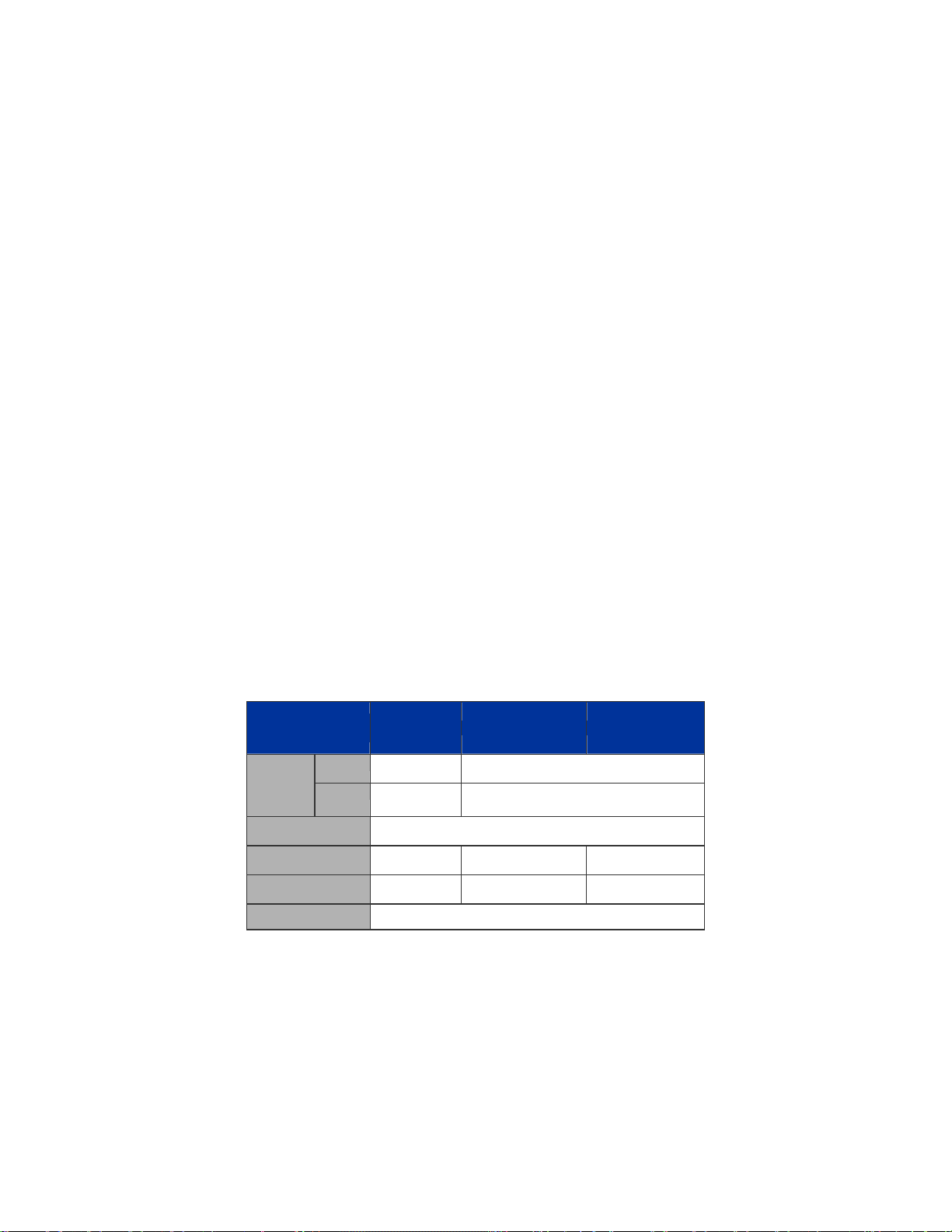
The below table lists the major hardware difference between the series model:
Model
(IFS)
Copper
Interface
Redundant Power
PoE Mode
PoE Budget
Stack Capability
Fiber 24, 100FX
GE-DSSG-244 GE-DSSG-244-POE NS3601-24P/4S
8 24
compatible
- af af
-
Hardware stacking, up to 16 units
4, 100FX compatible
-
220W 380W
10

IFS NS3601-24P/4S GE-DSSG-244 and 244-POE User Manual
1.3 How to Use This Manual
This User Manual is structured as follows:
Section 2, INSTALLATION
The section explains the functions of the Switch and how to physically install the Managed Switch.
Section 3, SWITCH MANAGEMENT
The section contains the information about the software function of the Managed Switch.
Section 4, WEB CONFIGURATION
The section explains how to manage the Managed Switch by Web interface.
Section 5, COMMAND LINE INTERFACE
The section describes how to use the Command Line interface (CLI).
Section 6, CLI CONFIGURATION
The section explains how to manage the Managed Switch by Command Line interface.
Section 7, SWITCH OPERATION
The chapter explains how to does the switch operation of the Managed Switch.
Section 8, POWER OVER ETHERNET OVERVIEW
The chapter introduce the IEEE 802.3af PoE standard and PoE provision of the Managed Switch.
Section 9, TROUBSHOOTING
The chapter explains how to trouble shooting of the Managed Switch.
Appendix A
The section contains cable information of the Managed Switch.
11

IFS NS3601-24P/4S GE-DSSG-244 and 244-POE User Manual
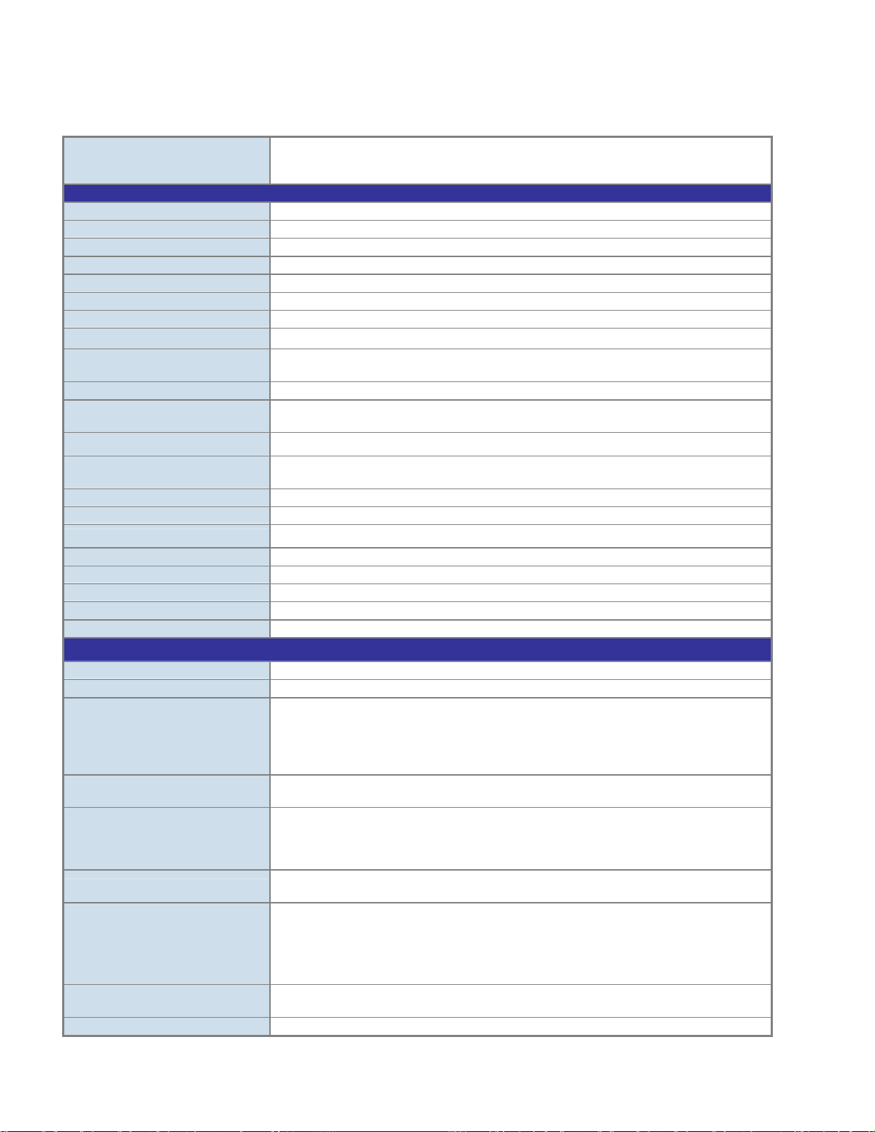
1.4 Product Features
¾ Physical Port
NS3601-24P/ 4S / GE-DSSG-244-POE
24-Port 10/100/1000Base-T Gigabit Ethernet RJ-45 with IEEE 802.3af PoE Injector
4 100/1000Base-X SFP slots, shared with Port-21 to Port-24
RS-232 DB9 console interface for Switch basic management and setup
2 High-performance 5GbE Stacking interface
GE-DSSG-244
24 100/1000Base-X mini-GBIC/SFP slots
8-Port 10/100/1000Base-T Gigabit Ethernet RJ-45, shared with Port-1 to Port-8
RS-232 DB9 console interface for Switch basic management and setup
2 High-performance 5GbE Stacking interface
¾ Layer 2 Features
■ Prevents packet loss with back pressure (Half-Duplex) and IEEE 802.3x PAUSE frame flow control (Full-Duplex)
■ High performance of Store-and-Forward architecture, broadcast storm control and runt/CRC filtering eliminates erroneous
packets to optimize the network bandwidth
■ Storm Control support:
− Broadcast / Multicast / Unknown-Unicast
■ Support VLAN
− IEEE 802.1Q Tagged VLAN
− Up to 255 VLANs groups, out of 4094 VLAN IDs
− Provider Bridging (VLAN Q-in-Q) support (IEEE 802.1ad)
− Private VLAN Edge (PVE)
− Voice VLAN
■ Support Spanning Tree Protocol
− STP, IEEE 802.1D Spanning Tree Protocol
− RSTP, IEEE 802.1w Rapid Spanning Tree Protocol
− MSTP, IEEE 802.1s Multiple Spanning Tree Protocol, spanning tree by VLAN
− BPDU Guard
■ Support Link Aggregation
− 802.3ad Link Aggregation Control Protocol (LACP)
− Cisco ether-channel (Static Trunk)
− Maximum 12 trunk groups, up to 16 ports per trunk group
− Up to 16Gbps bandwidth(Duplex Mode)
■ Provide Port Mirror (many-to-1)
■ Port Mirroring to monitor the incoming or outgoing traffic on a particular port
¾ Quality of Service
■ Ingress Shaper and Egress Rate Limit per port bandwidth control
■ 4 priority queues on all switch ports
■ Traffic classification:
- IEEE 802.1p CoS
- TOS / DSCP / IP Precedence of IPv4/IPv6 packets
- IP TCP/UDP port number
- Typical network application
■ Strict priority and Weighted Round Robin (WRR) CoS policies
■ Supports QoS and In/Out bandwidth control on each port
■ Traffic-policing policies on the switch port
■ QoS Control List Wizard makes QoS creation and configuration easier and more quickly
12

IFS NS3601-24P/4S GE-DSSG-244 and 244-POE User Manual
■ DSCP remarking
¾ Multicast
■ Supports IGMP Snooping v1, v2 and v3
■ Querier mode support
■ IGMP Snooping port filtering
■ Multicast VLAN Registration (MVR) support
¾ Security
■ IEEE 802.1x Port-Based / MAC-Based network access authentication
■ Built-in RADIUS client to co-operate with the RADIUS servers
■ TACACS+ login users access authentication
■ RADIUS / TACACS+ users access authentication
■ IP-Based Access Control List (ACL)
■ MAC-Based Access Control List
■ Source MAC / IP address binding
■ DHCP Snooping to filter un-trusted DHCP messages
■ Dynamic ARP Inspection discards ARP packets with invalid MAC address to IP address binding
■ IP Source Guard prevents IP spoofing attacks
■ Auto DoS rule to defend DoS attack
■ IP address access management to prevent unauthorized intruder
¾ Management
■ Switch Management Interfaces
- Console / Telnet Command Line Interface
- Web switch management
- SNMP v1, v2c, and v3 switch management
- SSH / SSL secure access
■ Four RMON groups (history, statistics, alarms, and events)
■ IPv6 IP Address / NTP / DNS management
■ Built-in Trivial File Transfer Protocol (TFTP) client
■ BOOTP and DHCP for IP address assignment
■ Firmware upload/download via HTTP / TFTP
■ DHCP Relay
■ User Privilege levels control
■ NTP (Network Time Protocol)
■ Link Layer Discovery Protocol (LLDP) Protocol
■ Cable Diagnostic technology provides the mechanism to detect and report potential cabling issues
■ Reset button for system reboot or reset to factory default
■ IFS Smart Discovery Utility for deploy management
■ ICMPv6
¾ Stacking
■ Hardware stack up to 16 units and 384 ports
■ Stacking architecture supports Chain and Ring mode
■ Mirror across stack
■ Link Aggregation groups spanning multiple switches in a stack
■ Hardware learning with MAC table synchronization across stack
¾ Power over Ethernet (NS3601-24P/4S / GE-DSSG-244-POE)
■ Complies with IEEE 802.3af Power over Ethernet End-Span PSE
■ Up to 24 ports for IEEE 802.3af devices powered
■ Support PoE Power up to 15.4 watts for each PoE ports
■ Auto detect powered device (PD)
■ Circuit protection prevent power interference between ports
■ Remote power feeding up to 100m
■ PoE Management
■ Total PoE power budget control
■ Pert port PoE function enable/disable
■ PoE Port Power feeding priority
■ Per PoE port power limit
■ PD classification detection
13
IFS NS3601-24P/4S GE-DSSG-244 and 244-POE User Manual
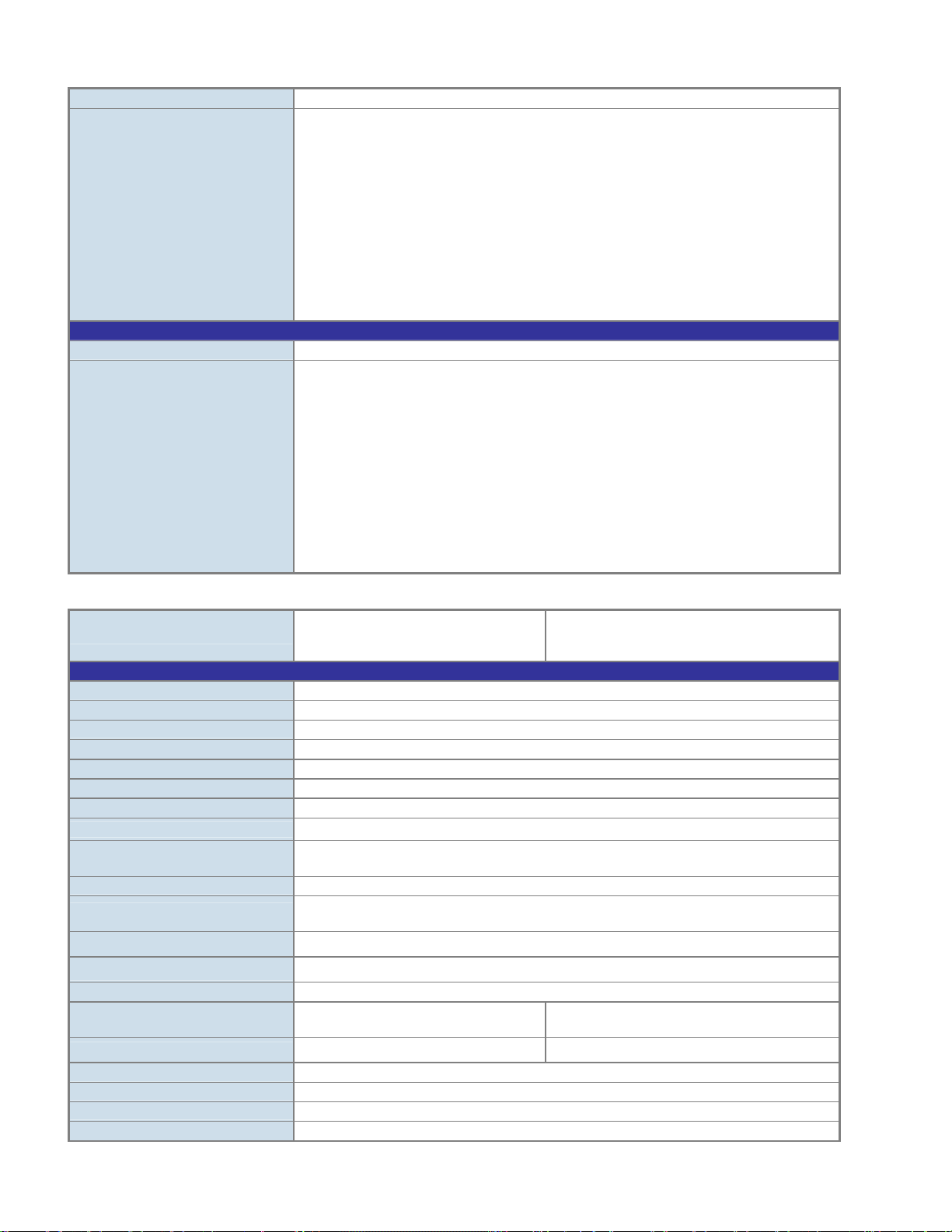
1.5 Product Specification
IFS Stackable Fiber Switch
Product GE-DSSG-244
Hardware Specification
Copper Ports
SFP/mini-GBIC Slots
Console Port
Stacking Ports
Switch Fabric
Address Table
Share data Buffer
Switch Processing Scheme
Flow Control
Jumbo Frame
Reset Button
Dimension (W x D x H)
Weight
LED
Power Consumption
Power Requirement – AC
Power Requirement – DC
Stacking Numbers
Stacking Bandwidth
Stack ID Display
ESD Protection
Layer 2 Function
Basic Management Interfaces
Secure Management Interface
Port configuration
Port Status
VLAN
Port trunking
QoS
IGMP Snooping
Access Control List
8 10/ 100/1000Base-T RJ-45 Auto-MDI/MDI-X ports, shared with Port-1~Port-8
24 100/1000Base-X Dual Speed SFP interfaces
1 x RS-232 DB9 serial port (115200, 8, N, 1)
2 5GbE / Cross-HDMI interface
68Gbps / non-blocking
8K entries, automatic source address learning and ageing
1392 kilobytes
Store-and-Forward
IEEE 802.3x Pause Frame for Full-Duplex
Back pressure for Half-Duplex
10Kbytes
< 5 seconds: System reboot
> 10 seconds: Factory Default
440 x 200 x 44.5 mm, 1U high
3.0kg
Power, Link/Act and speed per Gigabit port
Max. 30.2 watts / 102.98 BTU
AC 100~240V, 50/60Hz
---
16
10Gbps Full-Duplex
7-Segment LED Display (1~9, A~F,0)
6KV DC
Console, Telnet, Web Browser, SNMPv1, v2c and v3
SSH, SSL, SNMP v3
Port disable/enable.
Auto-negotiation 10/100/1000Mbps full and half duplex mode selection.
Flow Control disable / enable.
Bandwidth control on each port.
Power saving mode control
Display each port’s speed duplex mode, link status, Flow control status.
Auto negotiation status, trunk status.
802.1Q Tagged Based VLAN ,up to 255 VLAN groups
Q-in-Q
Private VLAN
Voice VLAN
IEEE 802.3ad LACP / Static Trunk
Support 12 groups of 16-Port trunk support
Traffic classification based, Strict priority and WRR
4-level priority for switching
- Port Number
- 802.1p priority
- DS/TOS field in IP Packet
IGMP (v1/v2) Snooping, up to 255 multicast Groups
IGMP Querier mode support
IP-Based ACL / MAC-Based ACL
14
SNMP MIBs
Standards Conformance
Regulation Compliance
Standards Compliance
IFS Stackable PoE models
IFS NS3601-24P/4S GE-DSSG-244 and 244-POE User Manual
Up to 256 entries
RFC-1213 MIB-II
IF-MIB
RFC-1493 Bridge MIB
RFC-1643 Ethernet MIB
RFC-2863 Interface MIB
RFC-2665 Ether-Like MIB
RFC-2737 Entity MIB
RFC-2618 RADIUS Client MIB
RFC-2933 IGMP-STD-MIB
RFC3411 SNMP-Frameworks-MIB
IEEE 802.1X PAE
LLDP
MAU-MIB
FCC Part 15 Class A, CE
IEEE 802.3 10Base-T
IEEE 802.3u 100Base-TX/100Base-FX
IEEE 802.3z Gigabit SX/LX
IEEE 802.3ab Gigabit 1000T
IEEE 802.3x Flow Control and Back pressure
IEEE 802.3ad Port trunk with LACP
IEEE 802.1D Spanning Tree protocol
IEEE 802.1w Rapid Spanning Tree protocol
IEEE 802.1s Multiple Spanning Tree
IEEE 802.1p Class of service
IEEE 802.1Q VLAN Tagging
IEEE 802.1x Port Authentication Network Control
IEEE 802.1ab Link Layer Discovery Protocol (LLDP)
Product GE-DSSG-244-POE NS3601-24P/4S
Hardware Specification
Copper Ports
SFP/mini-GBIC Slots
Console Port
Stacking Ports
Switch Fabric
Address Table
Share data Buffer
Switch Processing Scheme
Flow Control
Jumbo Frame
Reset Button
Dimension (W x D x H)
Weight
LED
Power Consumption
Power Requirement – AC
Stacking Numbers
Stacking Bandwidth
Stack ID Display
ESD Protection
24 10/ 100/1000Base-T RJ-45 Auto-MDI/MDI-X ports
4 SFP interfaces, shared with Port-21 to Port-24
1 x RS-232 DB9 serial port (115200, 8, N, 1)
2 5GbE / Cross-HDMI interface
68Gbps / non-blocking
8K entries, automatic source address learning and ageing
1392 kilobytes
Store-and-Forward
IEEE 802.3x Pause Frame for Full-Duplex
Back pressure for Half-Duplex
10Kbytes
< 5 seconds: System reboot
> 10 seconds: Factory Default
440 x 300 x 44.5 mm, 1U high
4.5kg
Power, Link/Act and speed per Gigabit port
Max. 290 watts /
989 BTU
AC 100~240V, 50/60Hz AC 100~240V, 50/60Hz
16
10Gbps Full-Duplex
7-Segment LED Display (1~9, A~F,0)
6KV DC
Max. 430.2 watts /
1467 BTU
15
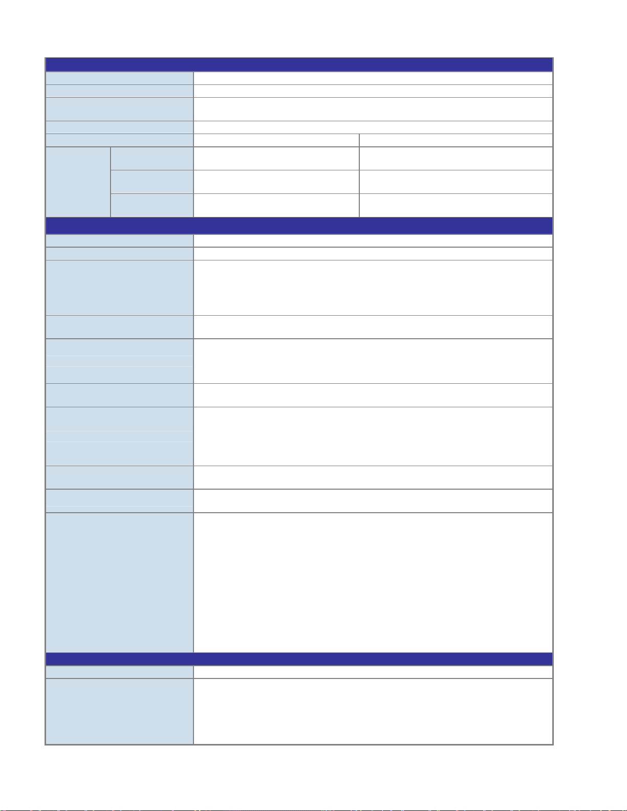
Power over Ethernet
PoE Standard
PoE Power Supply Type
PoE Power Output
Power Pin Assignment
PoE Power Budget
Number of PD @
7Watts
PoE Ability
Layer 2 Function
Basic Management Interfaces
Secure Management Interface
Port configuration
Port Status
VLAN
Port trunking
QoS
IGMP Snooping
Access Control List
SNMP MIBs
Standards Conformance
Regulation Compliance
Standards Compliance
Number of PD @
15.4Watts
Number of PD @
30.8Watts
IFS NS3601-24P/4S GE-DSSG-244 and 244-POE User Manual
IEEE 802.3af PoE / PSE
End-Span
Per Port 48V DC.
Max. 15.4 watts
1/2(+), 3/6(-)
220 Watts 380 Watts
24 24
14 24
- -
Console, Telnet, Web Browser, SNMPv1, v2c and v3
SSH, SSL, SNMP v3
Port disable/enable.
Auto-negotiation 10/100/1000Mbps full and half duplex mode selection.
Flow Control disable / enable.
Bandwidth control on each port.
Power saving mode control
Display each port’s speed duplex mode, link status, Flow control status.
Auto negotiation status, trunk status.
802.1Q Tagged Based VLAN ,up to 255 VLAN groups
Q-in-Q
Private VLAN
Voice VLAN
IEEE 802.3ad LACP / Static Trunk
Support 12 groups of 16-Port trunk support
Traffic classification based, Strict priority and WRR
4-level priority for switching
- Port Number
- 802.1p priority
- DS/TOS field in IP Packet
IGMP (v1/v2) Snooping, up to 255 multicast Groups
IGMP Querier mode support
IP-Based ACL / MAC-Based ACL
Up to 256 entries
RFC-1213 MIB-II
IF-MIB
RFC-1493 Bridge MIB
RFC-1643 Ethernet MIB
RFC-2863 Interface MIB
RFC-2665 Ether-Like MIB
RFC-2737 Entity MIB
RFC-2618 RADIUS Client MIB
RFC-2933 IGMP-STD-MIB
RFC3411 SNMP-Frameworks-MIB
IEEE 802.1X PAE
LLDP
MAU-MIB
FCC Part 15 Class A, CE
IEEE 802.3 10Base-T
IEEE 802.3u 100Base-TX/100Base-FX
IEEE 802.3z Gigabit SX/LX
IEEE 802.3ab Gigabit 1000T
IEEE 802.3x Flow Control and Back pressure
IEEE 802.3ad Port trunk with LACP
16

IFS NS3601-24P/4S GE-DSSG-244 and 244-POE User Manual
IEEE 802.1d Spanning tree protocol
IEEE 802.1w Rapid spanning tree protocol
IEEE 802.1s Multiple spanning tree protocol
IEEE 802.1p Class of service
IEEE 802.1Q VLAN Tagging
IEEE 802.1x Port Authentication Network Control
IEEE 802.1ab LLDP
RFC 768 UDP
RFC 793 TFTP
RFC 791 IP
RFC 792 ICMP
RFC 2068 HTTP
RFC 1112 IGMP version 1
RFC 2236 IGMP version 2
IEEE 802.3af Power over Ethernet
IEEE 802.3at Power over Ethernet (Pre-Standard)
Note: The PoE networks of this equipment is to be connected without routing to the outside plant.
17
IFS NS3601-24P/4S GE-DSSG-244 and 244-POE User Manual
2. INSTALLATION
This section describes the hardware features and installation of the Managed Switch on the desktop or rack mount. For easier
management and control of the Managed Switch, familiarize yourself with its display indicators, and ports. Front panel illustrations in
this chapter display the unit LED indicators. Before connecting any network device to the Managed Switch, please read this chapter
completely.
2.1 Hardware Description
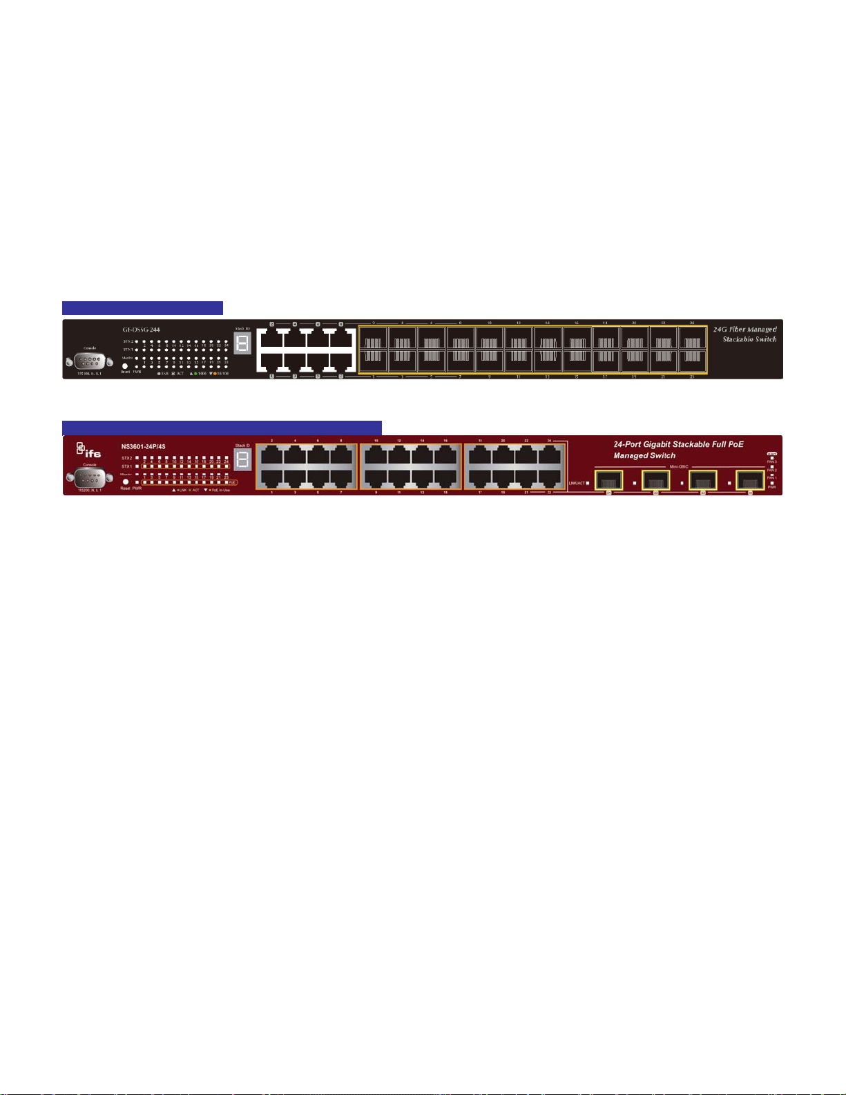
2.1.1 Switch Front Panel
The unit front panel provides a simple interface monitoring the switch. Figure 2-1 to 2-2 shows the front panel of the Managed
Switches.
GE-DSDG-244 Front Panel
Figure 2-1 GE-DSSG-244 front panel.
IFS NS3601-24P/4S / GE-DSSG-244-POE Front Panel
Figure 2-2 IFS NS3601-24P/4S / GE-DSSG-244-POE front panel.
■ Gigabit TP interface
10/100/1000Base-T Copper, RJ-45 Twist-Pair: Up to 100 meters.
■ Gigabit SFP slots
1000Base-SX/LX mini-GBIC slot, SFP (Small Factor Pluggable) transceiver module: From 550 meters (Multi-mode fiber), up to
10/30/50/70 kilometers (Single-mode fiber).
■ Console Port
The console port is a DB9, RS-232 male serial port connector. It is an interface for connecting a terminal directly. Through the
console port, it provides rich diagnostic information includes IP Address setting, factory reset, port management, link status and
system setting. Users can use the attached RS-232 cable in the package and connect to the console port on the device. After
the connection, users can run any terminal emulation program (Hyper Terminal, ProComm Plus, Telix, Winterm, etc.) to enter
the startup screen of the device.
18
IFS NS3601-24P/4S GE-DSSG-244 and 244-POE User Manual
■ Reset button
On the left hand side of the front panel, the reset button is designed for rebooting the Managed Switch without a power cycle.
The following is the summary table of Reset button functions:
Reset Button Pressed and Released Function
< 5 sec: System reboot Reboot the Managed Switch
Reset the Managed Switch to Factory Default configuration.
The Managed Switch will then reboot and load the default
settings as below:
> 5 sec: Factory Default
■ Stack ID
Each IFS Managed Stackable Switch on a stack must have a unique “Stack ID”. There are 16 degrees (0~9, A~F) in the rotary
switch. The Stack ID is configured via Web or CLI management interface. Use the Stack ID to identify the location of the real
device.
。 Default Username: admin
。 Default Password: admin
。 Default IP address: 192.168.0.100
。 Subnet mask: 255.255.255.0
。 Default Gateway: 192.168.0.254
Stack ID is not equal to the Master Priority that is configured in the management interface.
■ Master LED
If master switch fails or is disconnected to the switch by stack port, the switch with lowest switch ID will become the master.
19

IFS NS3601-24P/4S GE-DSSG-244 and 244-POE User Manual
2.1.2 LED Indications
The front panel LEDs indicates instant status of port links, data activity and system power; helps monitor and troubleshoot when
needed. Figure 2-3 & Figure 2-4 shows the LED indications of these Managed Switches.
NS3601-24P/4S /GE-DSSG-244-POE LED indication
Figure 2-3 GE-DSSG-244-POE / NS3601-24P/4S LED panel
System
LED Color Function
PWR Green Illuminates to indicate that the Switch has power.
SYS Green Illuminates to indicate the system is on.
Alert
LED Color Function
PWR Alert Green
FAN1 Green
FAN2 Green
FAN3 Green
Per 10/100Mbps port, PoE interfaces (Port-1 to Por-24)
LED Color Function
LNK/ACT Green
PoE In-Use Orange
Illuminates to indicate that the PoE power supply has failed.
Illuminates to indicate that the FAN1 has failed.
Illuminates to indicate that the FAN2 has failed.
Illuminates to indicate that the FAN3 has failed.
Illuminates:
Blink:
Illuminates:
Off:
To indicate the link through that port is successfully established.
To indicate that the Switch is actively sending or receiving data over that port.
To indicate the port is providing 52V DC in-line power.
To indicate the connected device is not a PoE Powered Device (PD).
20
Per 10/100/1000Base-T port / SFP interfaces
LED Color Function
Illuminates:
Blink:
Off:
Illuminates:
Blink:
Off:
1000
LNK/ACT
10/100
LNK/ACT
Green
Green
1. Press the RESET button for 5 seconds. The Managed Switch will reboot automatically.
2. Press the RESET button for 10 seconds . The Managed Switch will restore back to the factory default
mode; the entire configuration will be erased.
IFS NS3601-24P/4S GE-DSSG-244 and 244-POE User Manual
To indicate the link through that port is successfully established with speed
1000Mbps.
To indicate that the Switch is actively sending or receiving data over that port.
If 10/100 LNK/ACT LED is light, it indicates that the port is operating at
10Mbps or 100Mbps. If LNK/ACT LED is Off, it indicates that the port is link
down.
To indicate the link through that port is successfully established with speed
10Mbps or 100Mbps.
To indicate that the Switch is actively sending or receiving data over that port.
If 1000 LNK/ACT LED is ON, it indicates that the port is operating at
1000Mbps.
If 1000 LNK/ACT LED is Off, it indicates that the port is link down.
3. The 2 Gigabit TP/SFP combo ports are shared with port 25/26 of Managed Switch. Either of them can
operate at the same time.
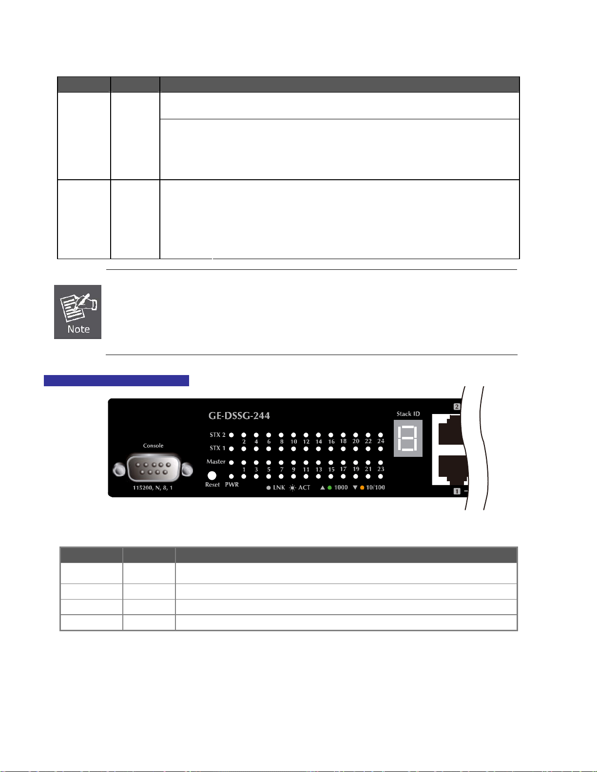
GE-DSSG-244 LED indication
■ System
LED Color Function
PWR Green
Master Green Illuminates to indicate that the Switch is the Master of the stack group
STX1 Green Illuminates to indicate the stacking link through that port is successfully established.
STX2 Green Illuminates to indicate the stacking link through that port is successfully established.
Illuminates to indicate that the Switch is powered on.
Blink to indicate the System is running under booting procedure.
Figure 2-4 GE-DSSG-244 LED panel
21
IFS NS3601-24P/4S GE-DSSG-244 and 244-POE User Manual
■ 10/100/1000Base-T interfaces (Shared Port-1~Port-8)
LED Color Function
illuminates:
To indicate the link through that port is successfully established with speed
1000Mbps
1000
LNK/ACT
10/100
LNK/ACT
■ 100 / 1000Base-X SFP interfaces
LED Color Function
1000
LNK
100
LNK/ACT
■ 7-Segment LED Display
Stack ID (1~9, A~F, 0): To indicate the Switch ID of each SGSW Managed Switch. Switch IDs are used to uniquely identify the
Managed Switches within a stack. The Switch ID of each Managed Switch is shown on the display on the front of the Managed
Switch and is used widely in the web pages as well as in the CLI commands of the Stack group.
Stack ID 1 2 3 4 5 6 7 8 9 A. B. C. D. E. F. 0
Switch ID 1 2 3 4 5 6 7 8 9 10 11 12 13 14 15 16
Green
Orange
Green
Orange
Blink:
Off:
Illuminates:
Blink:
Off:
Illuminates:
Off:
Illuminates:
Blink:
Off:
To indicate that the switch is actively sending or receiving data over that
port.
If L10/100 NK/ACT LED light-> indicate that the port is operating at 10Mbps
or 100Mbps
If LNK/ACT LED Off -> indicates that the port is link down
To indicate the link through that port is successfully established with speed
10Mbps or 100Mbps
To indicate that the switch is actively sending or receiving data over that
port.
If 1000 LNK/ACT LED light-> indicates that the port is operating at
1000Mbps
If 1000 LNK/ACT LED Off -> indicates that the port is link down
To indicate the link through that SFP port is successfully established with
speed 1000Mbps
To indicate that the SFP port is link down
To indicate the link through that port is successfully established with speed
100Mbps
To indicate that the switch is actively sending or receiving data over that
port.
If 1000 LNK/ACT LED light-> indicate that the port is operating at
1000Mbps
If 1000 LNK/ACT LED Off -> indicate that the port is link down
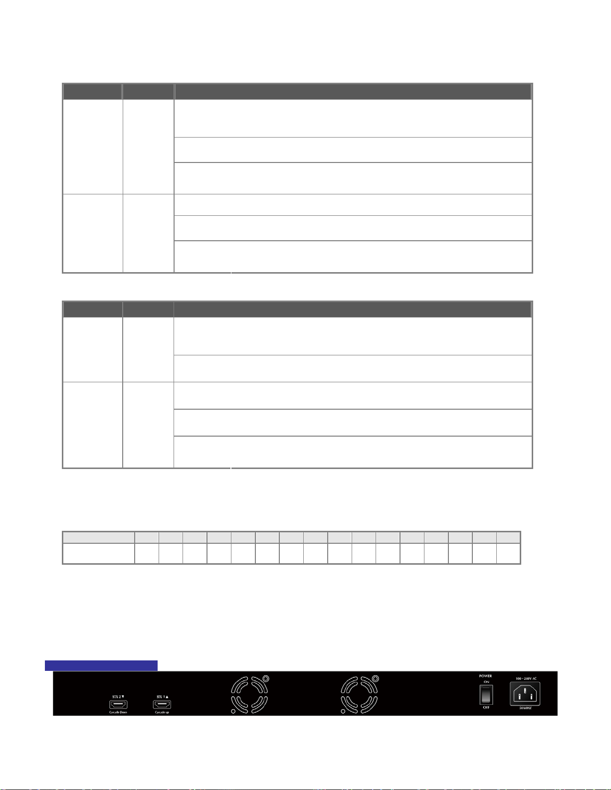
2.1.3 Switch Rear Panel
The rear panel of the Managed Switch indicates an AC inlet power socket, which works with the input power range from 100 to 240V
AC, 50-60Hz. Figure 2-5 & Figure 2-6 shows the rear panel of these Managed Switches.
GE-DSSG-244 Rear Panel
Figure 2-5 Rear panel of GE-DSSG-244
22

NS3601-24P/4S / GE-DSSG-244-POE Rear Panel
IFS NS3601-24P/4S GE-DSSG-244 and 244-POE User Manual
Figure 2-6 Rear panel of NS3601-24P/4SP and GE-DSSG-244-POE
■ AC Power Receptacle
For compatibility with electric service in most areas of the world, the Managed Switch’s power supply automatically adjusts to
line power in the range 100-240VAC and 50/60 Hz.
Plug the female end of the power cord firmly into the receptalbe on the rear panel of the Managed Switch. Plug the other end of
the power cord into an electric service outlet.
1. The device requires a power connection to operate. If your networks should active all the time,
please consider using UPS (Uninterrupted Power Supply) for your device. It will prevent you from
Power Notice:
network data loss or network downtime.
2. For additional protection against unregulated voltage or current surges, you may also want to
consider surge suppression as part of your installation.
2.2 Install the Switch
This section describes how to install your Managed Switch and make connections to the Managed Switch. Please read the following
topics and perform the procedures in the order being presented. To install your Managed Switch on a desktop or shelf, simply
complete the following steps.
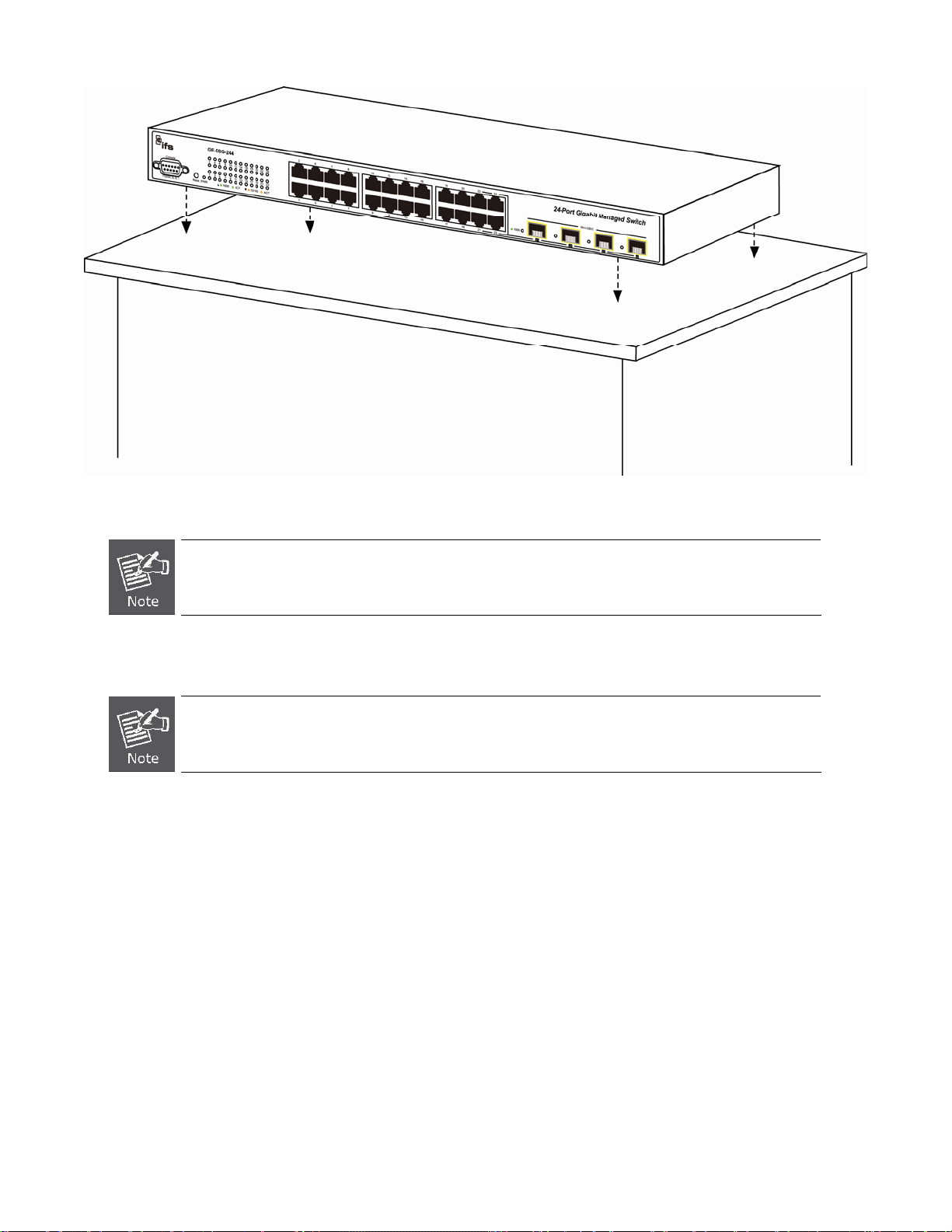
2.2.1 Desktop Installation
To install the Managed Switch on desktop or shelf, please follows these steps:
Step1: Attach the rubber feet to the recessed areas on the bottom of the Managed Switch.
Step2: Place the Managed Switch on the desktop or the shelf near an AC power source, as shown in Figure 2-7.
23
IFS NS3601-24P/4S GE-DSSG-244 and 244-POE User Manual
Figure 2-7 Place the Managed Switch on the desktop
Step3: Keep enough ventilation space between the Managed Switch and the surrounding objects.
When choosing a location, please keep in mind the environmental restrictions discussed in Chapter 1,
Section 5 Product Specification.
Step4: Connect the Managed Switch to network devices.
Connect one end of a standard network cable to the 10/100/1000 RJ-45 ports on the front of the Managed Switch
Connect the other end of the cable to the network devices such as printer servers, workstations or routers…etc.
Connection to the Managed Switch requires UTP Category 5 network cabling with RJ-45 tips. For more
information, please see the Cabling Specification in Appendix A.
24
IFS NS3601-24P/4S GE-DSSG-244 and 244-POE User Manual
Step5: Supply power to the Managed Switch.
Connect one end of the power cable to the Managed Switch.
Connect the power plug of the power cable to a standard wall outlet.
When the Managed Switch receives power, the Power LED should remain solid Green.
2.2.2 Rack Mounting
To install the Managed Switch in a 19-inch standard rack, please follows the instructions described below.
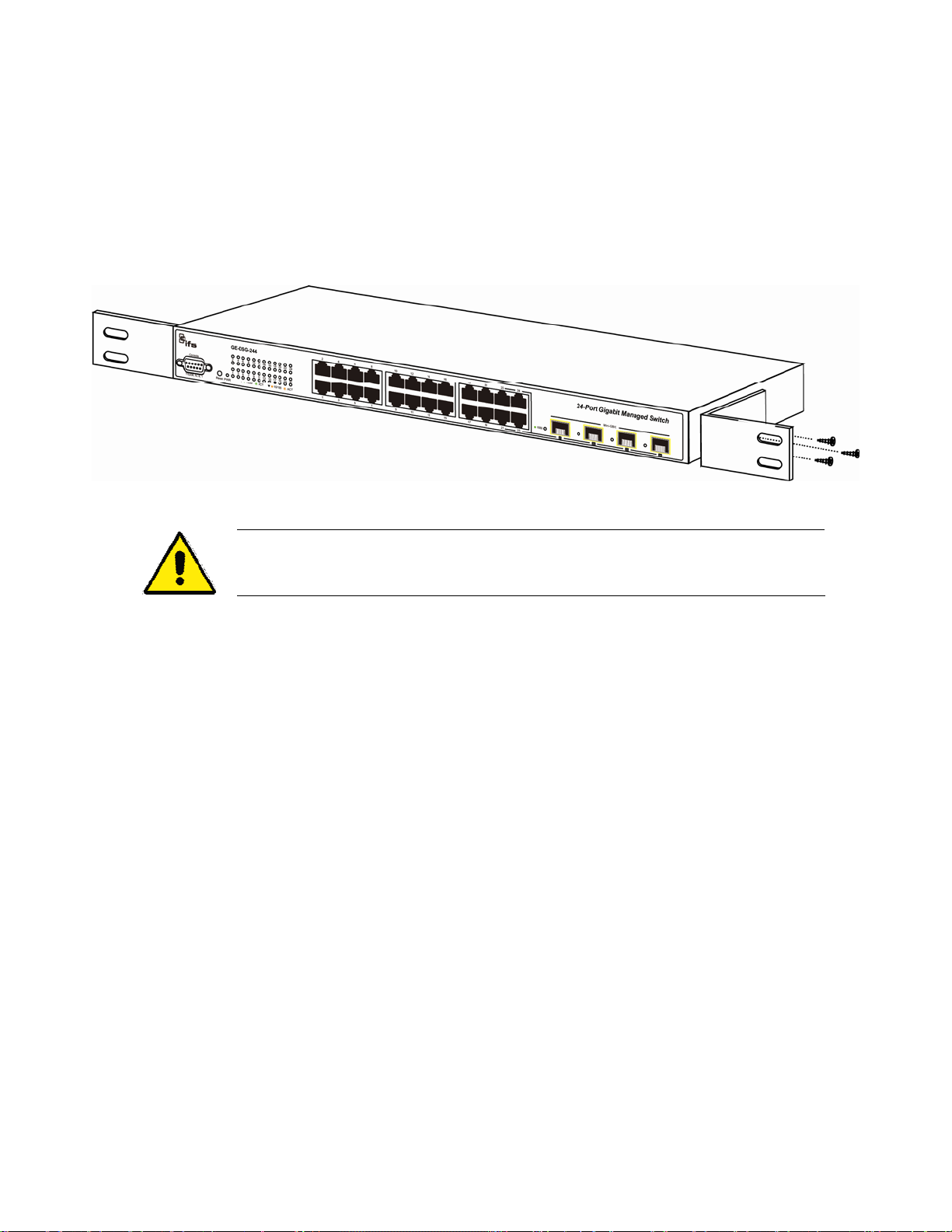
Step1: Place the Managed Switch on a hard flat surface, with the front panel positioned towards the front side.
Step2: Attach the rack-mount bracket to each side of the Managed Switch with supplied screws attached to the package.
Figure 2-8 shows how to attach brackets to one side of the Managed Switch.
Figure 2-8 Attach brackets to the Managed Switch.
You must use the screws supplied with the mounting brackets. Damage caused to the parts by
using incorrect screws would invalidate the warranty.
Step3: Secure the brackets tightly.
Step4: Follow the same steps to attach the second bracket to the opposite side.
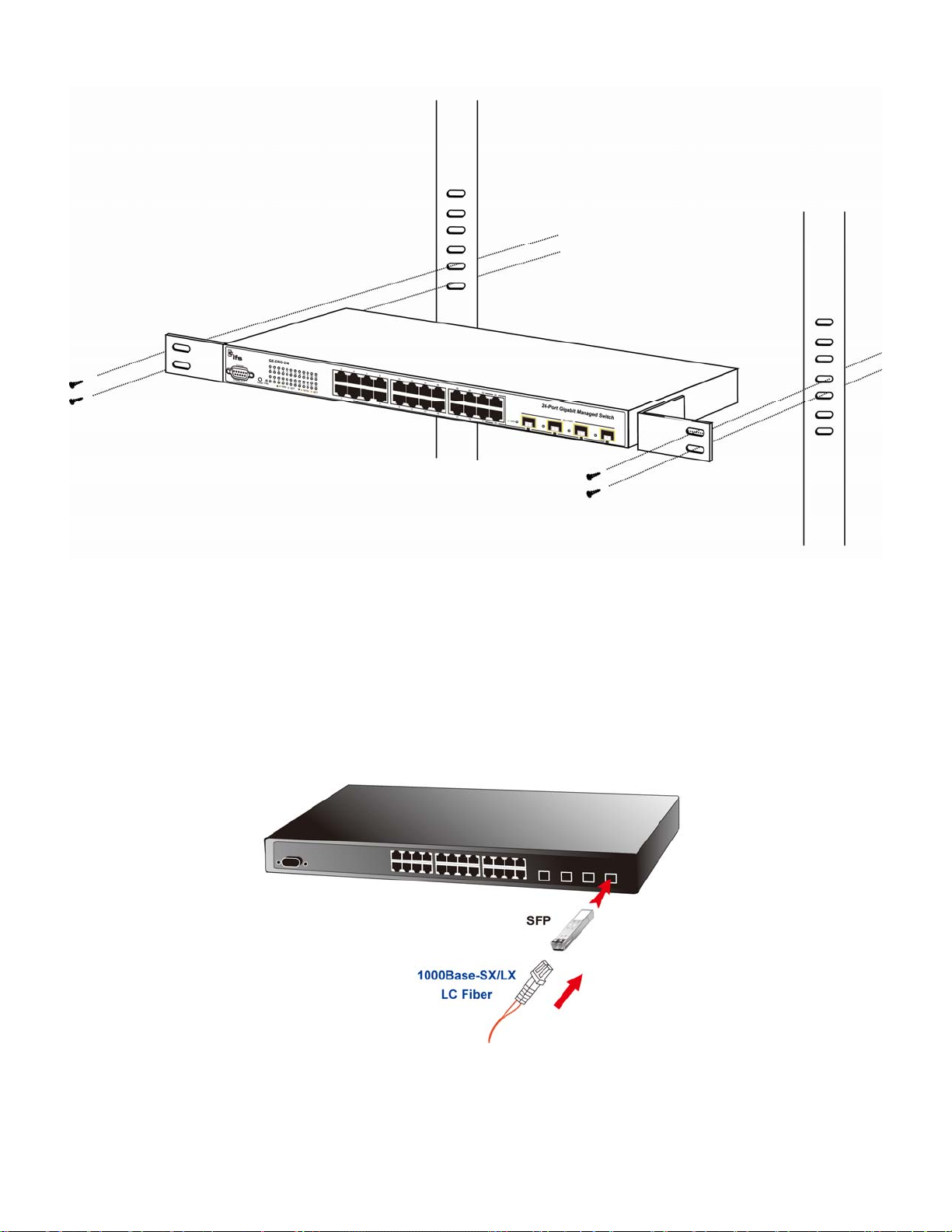
Step5: After the brackets are attached to the Managed Switch, use suitable screws to securely attach the brackets to the rack, as
shown in Figure 2-8.
25
IFS NS3601-24P/4S GE-DSSG-244 and 244-POE User Manual
Figure 2-8 Mounting IFS-24040 in a Rack
Step6: Proceeds with the steps 4 and steps 5 of session 2.2.1 Desktop Installation to connect the network cabling and supply power
to the Managed Switch.
2.2.3 Installing the SFP transceiver
The sections describe how to plug-in an SFP transceiver into an SFP slot.
The SFP transceivers are hot-swappable. You can plug-in and out the transceiver to/from any SFP port without a need to power
down the Managed Switch. As the Figure 2-9.
Figure 2-9 Plug-in the SFP transceiver
Approved IFS SFP Transceivers
IFS Managed switches supports both single mode and multi mode SFP transceivers. Please refer to below chart, as well as IFS
website for latest compatible SFP modules.
26
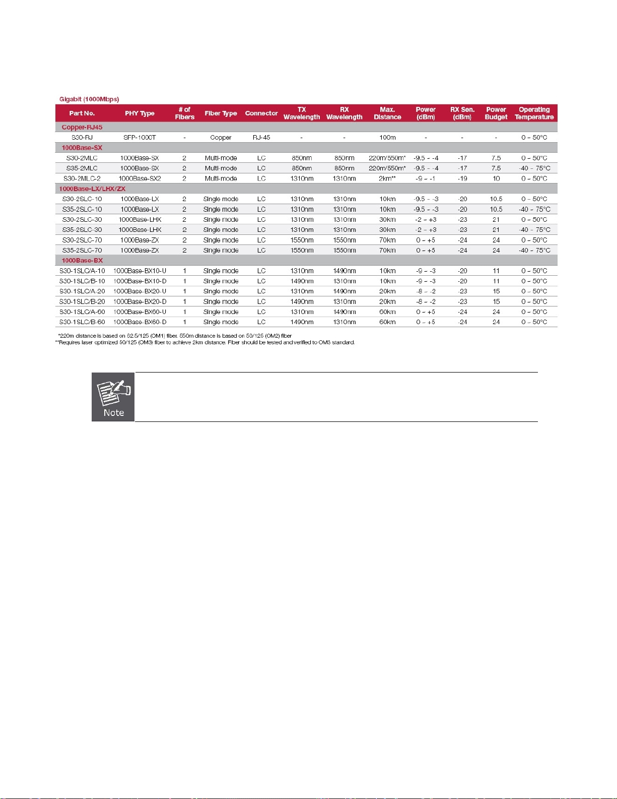
1000Base-SX/LX SFP transceiver:
IFS NS3601-24P/4S GE-DSSG-244 and 244-POE User Manual
We recommend using IFS SFPs on the Managed Switch. If you insert a SFP transceiver that is not
supported, the Managed Switch will not recognize it.
Before connecting the other switches, workstation or Media Converter:
1. Make sure both sides use the same SFP transceiver, for example: 1000Base-SX to 1000Base-SX, 1000Base-LX to
1000Base-LX.
2. Make sure the fiber-optic cable type match the SFP transceiver model.
¾ To connect to 1000Base-SX SFP transceiver, use the Multi-mode fiber cable- with one side must be male duplex LC
connector type.
¾ To connect to 1000Base-LX SFP transceiver, use the Single-mode fiber cable-with one side must be male duplex LC
connector type.
Connect the fiber cable
1. Attach the duplex LC connector on the network cable into the SFP transceiver.
2. Connect the other end of the cable to a device – switches with SFP installed, fiber NIC on a workstation or a Media Converter..
3. Check the LNK/ACT LED of the SFP slot on the front of the Managed Switch. Ensure that the SFP transceiver is operating
correctly.
4. Check the Link mode of the SFP port if the link failed.
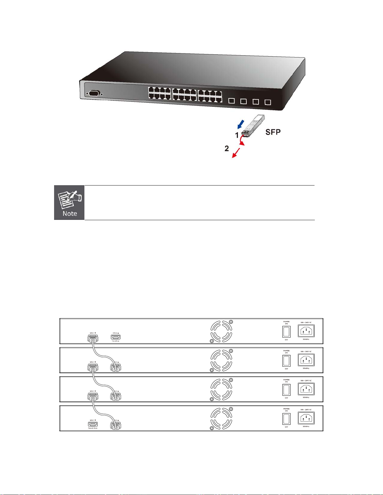
Remove the transceiver module
1. Make sure there is no network activity by consult or check with the network administrator. Or through the management
interface of the switch/converter (if available) to disable the port in advance.
2. Remove the Fiber Optic Cable gently.
3. Turn the handle of the MGB module to horizontal position.
4. Pull out the module gently with the handle.
27
IFS NS3601-24P/4S GE-DSSG-244 and 244-POE User Manual
Figure 2-10 Pull out the SFP transceiver
Never pull out the module without pull the handle or the push bolts on the module. Direct pull
out the module may damage the module and SFP module slot of the Managed Switch.
2.3 Stack Installation
IFS-NS3601-24P/4S and GE-DSSG Series
The IFS-NS3601-24P/4S and GE-DSSG series Managed Switch provides a switch stacking function to manage up to 16 switches
using a single IP address. And up to 384 Gigabit Ethernet ports can be managed by a stacking group and you can add ports and
functionality as needed. You can add IFS-NS3601-24P/4S and GE-DSSG series switches as needed to support more network
clients, knowing that your switching fabric will scale to meet increasing traffic demands.
Two types of stack topologies are supported by the IFS-NS3601-24P/4S and GE-DSSG series:
Chain topology (same as a disconnected ring)
Ring topology
Please find the following picture for sample connection.
Figure 2-11 Chain Stack topology
28
 Loading...