

Page 1
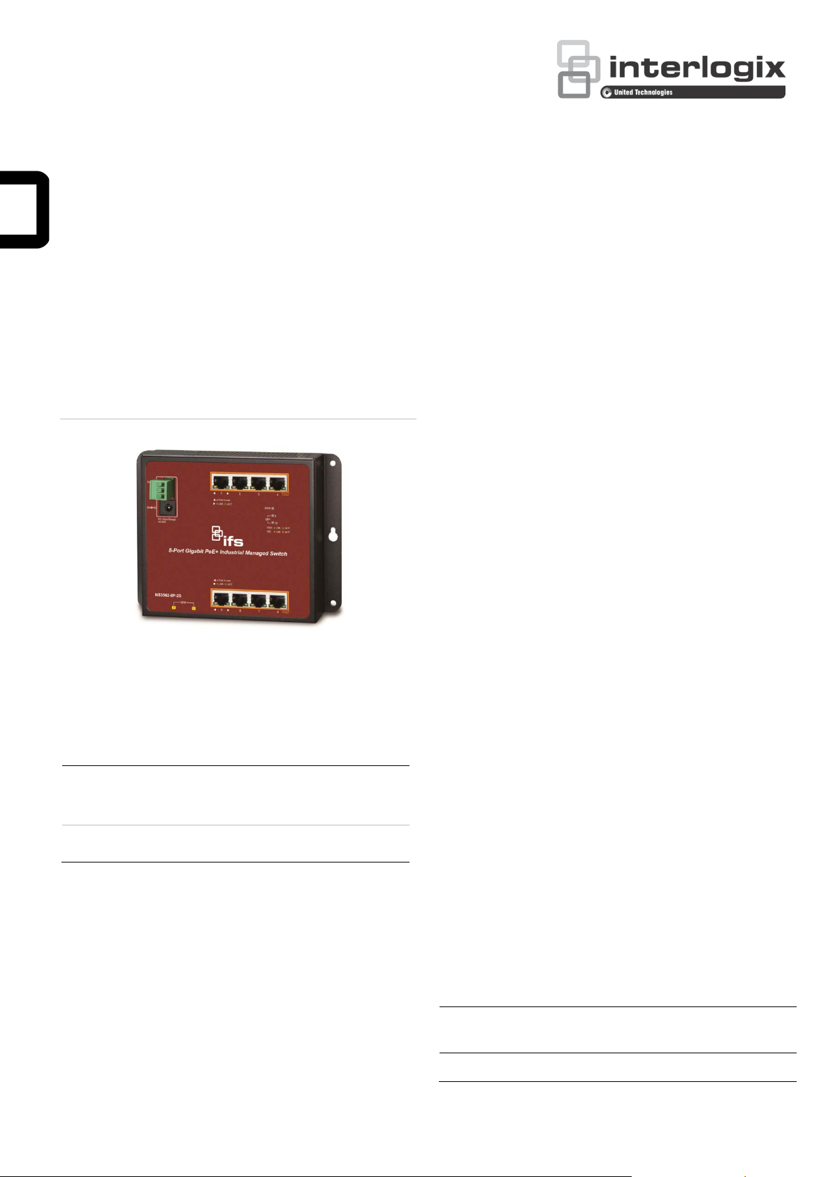
NS3562-8P-2S Industrial Wall-mount
Managed Gigabit Ethernet Switch Quick
Installation Guide
Figure 1: NS3562-8P-2S
1. Package Contents
Thank you for purchasing IFS Industrial Wall-mount
Managed Gigabit Switch, NS3562-8P-2S. The table
below shows the model with the number of ports:
Model
Name
NS3562-8P2S
10/100/1000T
Copper Ports
8 8 2
802.3at PoE
Ports
100/1000 SFP
Fiber Optical
Interface
RJ45 Dust Cap x 8
SFP Dust Cap x2
If any item is found missing or damaged, please contact
your local reseller for replacement.
2. Requirements
Workstations running Windows
XP/2003/Vista/7/8/2008/10, MAC OS X or later,
Linux, UNIX, or other platf orms are compatible with
TCP/IP protocols
Workstations are insta ll ed with Ethernet NIC
(Network Interface Card)
Ethernet Port Connection
Network cables - Use standard network (UTP)
cables with RJ45 connectors.
The above PC is installed with Web browser
and JAVA runtime environment plug-in.
Note: It is recommended to use Internet Explore 8.0 or
above to access the Wall-mount Managed S witc h. If the
Web interface of the Wall-mount Mana ged S witc h is not
accessible, please turn off the anti-virus software or
firewall and then try it again.
In the following section, unless specified, the term “Wall-
mount Managed Switch” mentioned in this quick
installation guide refers to the NS3562-8P2S.
Open the box of the Wall-mount Managed S witch and
carefully unpack it. The box should contain the following
items:
The Wall-mount Man ag ed S witch x 1
Quick Installation Guide x 1
3-pin Terminal Block Connector x 1
Wall-mounted Kit x 1
P/N 107322-EN • REV A • ISS 21SEP16 1
3. Wiring the Power Inputs
The Wall-mount Man ag ed S witch features a strong dual
power input system (Terminal block and DC jack)
incorporated into the customer’s automation network to
enhance system reliability and uptime.
Range Model
NS3562-8P-2S 48~56V DC 48~56V DC
3-pin Terminal Block DC Jack
Power Input
Page 2
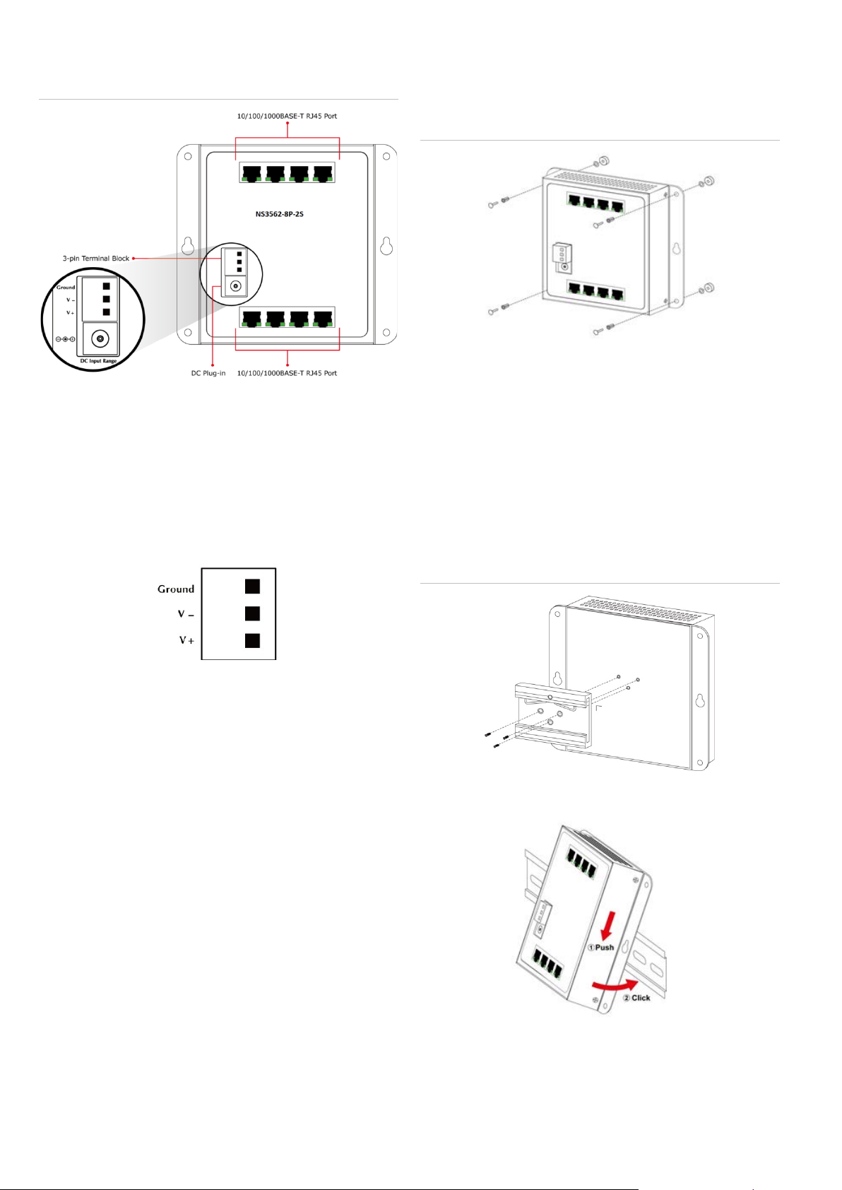
Figure 2: DC Power Input
V+ = Positive / V- = Negative / Ground
3.1 Terminal Block Connector Pinout
To install the 3-pin Terminal Block Connector on the
Wall-mount Manag ed S witch, follow these steps:
Step 1: Insert positive DC po wer wire into V+, negativ e
DC power wire into V-, and grounding wire into
Ground.
Step 3: Screw the bolts into the conductor pipe. The
Wall-mount Manag ed S witch is between bolts and
conductor pipe, as shown below.
Figure 3: Wall Mount install
4.3 DIN-rail Mount Installation
The DIN-rail kit is included in the package. When the
wall-mount application for the Wall-mount Managed
Switch needs to be replaced with DIN-rail application,
please refer to the following figures to screw the DIN-rail
on the Wall-mount Managed Switch. To hang up the
Wall-mount Manag ed S witch, follow the steps below:
Step 1: Screw the DIN-rail on the Wall-mount Managed
Switch.
Step 2: Tighten the wire-clamp screws for preventing the
wires from loosening and plug into the Wall-mount
Managed switch
Note:
1. The wire gauge should be in the range from 12
to 24 AWG.
2. The device must be grounded.
4. Installation
4.1 Wall Mount Installation
To install the Wall-mount Managed Switc h on the wall,
follow these steps:
Step 1: There are 4 holes with 8 mm diameter on the
wall; the distance between the 2 holes is 133 mm
and the line through them must be horizontal.
Step 2: Install a conductor pipe inside the board hole
and flush the edge of the conductor pipe with the
wall surface.
Figure 4: DIN Rail install
Step 2: Lightly insert the button of DIN-rail into the track.
Step 3: Check whether the DIN-rail is tightly on the
track.
2 NS3562-8P-2S Industrial Wall-mount Managed Gigabit Ethernet Switch Quick Installation Guide
Page 3

5. Starting Web Management
The following shows how to start up the Web
Management of the Wall-mount Managed Switch. Note
the Wall-mount Ma nag ed S witc h is configured through
an Ethernet connection. Please make sure the manager
PC must be set to the same IP subnet address.
For example, the default IP address of the Wall-mount
Managed Switch is 192.168.0.100, then the manager PC
should be set to 192.168.0.x (where x is a number
between 1 and 254, except 100) and the default subnet
mask is 255.255.255.0.
Figure 5: IP Management Diagram
3. After entering the password, the main screen, as
shown in Figure 7.
Note: The following web screen is based on the WGS4215-8T2S. The display of the WGS-4215-8T2S is the
same as those of the WGS-804HPT and WGS-42158T/WGS-4215-8P2S.
Figure 7: Web Main Screen of Wall-mount Managed Switch
The Switch Menu on the left of the Web page lets you
access all the commands and statistics the Wall-mount
Managed Switch provides.
Figure 8: Switch Menu
Logging in to the Wall-mount Managed Switch
1. Use Internet Explorer 8.0 or above Web browser
and enter IP address http://192.168.0.100 to access
the Web interface.
2. When the following dialog box appears, please enter
“admin” in both the defaul t user name and
password fields. The login screen in Figure 6
appears.
Default Username: admin
Default Password: admin
Now, you can use the Web management interface to
Figure 6: Web Login Screen
continue the Switch management. Please refer to the
user’s manual for more.
6. Saving Configuration via the We b
In the Wall-mount Managed Switch, the running
configuration file stores in the RAM. In the current
version, the running configuration sequence of runningconfig can be saved from the RAM to FLASH by ”Save
NS3562-8P-2S Industrial Wall-mount Managed Gigabit Ethernet Switch Quick Installation Guide 3
Configurations to FLASH” function, so that the running
Page 4

configuration sequence becomes the startup
configuration file, which is called configuration save.
http://www.Interlogix.com/support
To save all applied changes and set the current
configuration as a startup configuration, the startupconfiguration file will be loaded automatically across a
system reboot.
1. Click ”Save > Save Configurations to FLASH” to
login “Configuration Manager” Page.
2. Press the “Apply” button to save running
configuration to start up configuration.
Copyright
© 2016 United Technologies Corporation.
Interlogix is part of UTC Climate, Controls & Security, a
unit of United Technologies Corporation. All rights
reserved.
Trademarks and patents
Trade names used in this document may be trademarks
or registered trademarks of the manufacturers or
vendors of the respective products.
7. Recovering Back to Default
Configuration
IP Address has been changed or admin password has been forgotten
To reset the IP address to the default IP address
“192.168.0.100” or reset the login password to default
value, press the reset button on the front panel for
about 5 seconds. After the device is rebooted, you can
login the Web interface management within the same
subnet of 192.168.0.xx.
Figure 9: NS3562-8P-2S Reset Button
8. Customer Support
Thank you for purchasing IFS products. You can browse
our online FAQ resource and User’s Manual on IFS Web
site first to check if it could solve your issue. If you need
more support information, please contact IFS switch
support team.
Look under transmission products.
IFS online FAQ:
http://www.Interlogix.com/support
Switch support team mail address:
4 NS3562-8P-2S Industrial Wall-mount Managed Gigabit Ethernet Switch Quick Installation Guide
 Loading...