

Page 1
NS3552
NS3552-8P-2S-V2 Quick Installation Guide
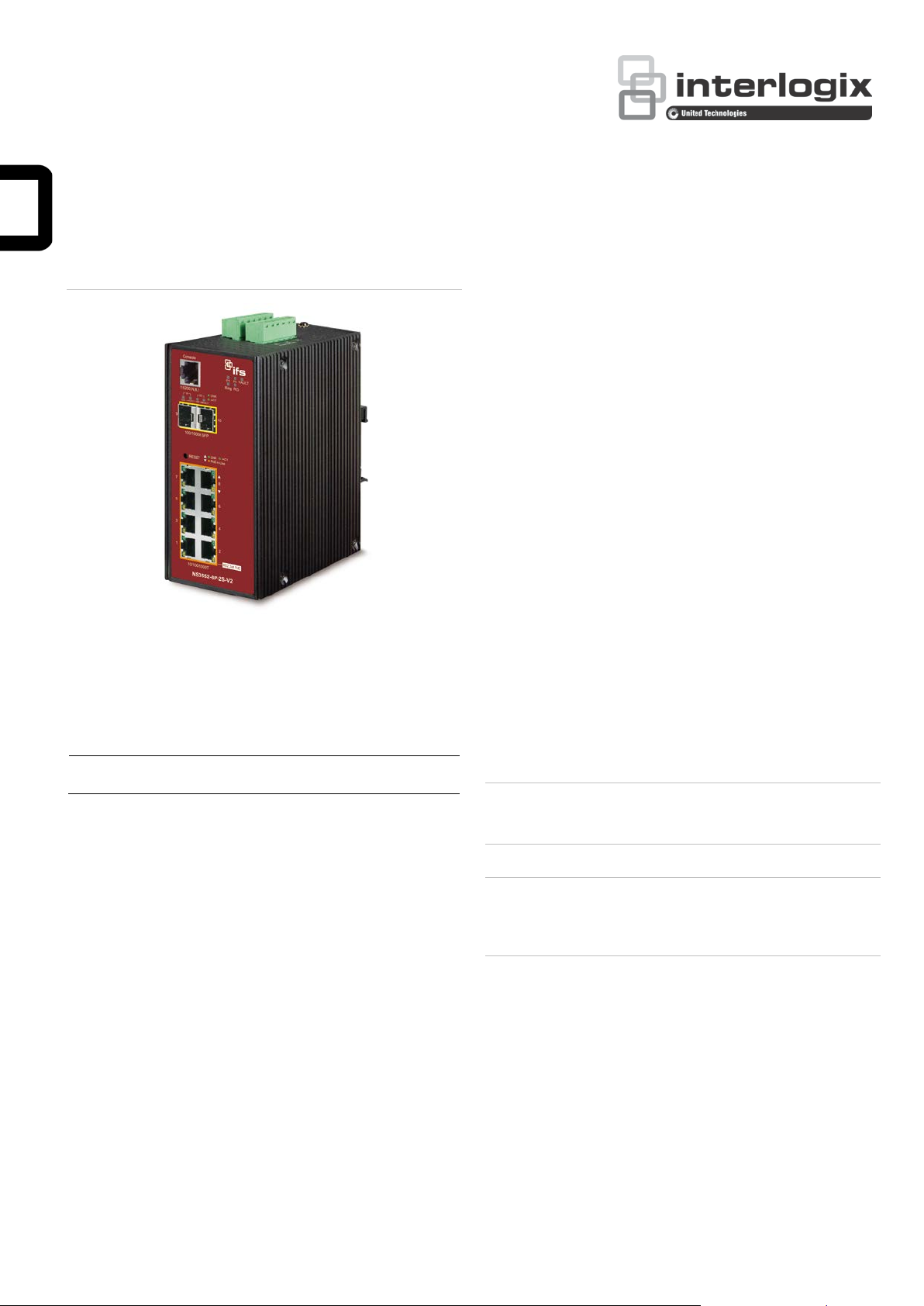
Figure 1: NS3552-8P-2S-V2 Industrial L2+ Multi-Port Managed
Ethernet Switch
Requirements
The industrial managed switch provides a remote login
interface for management purposes. The following equipment
is necessary for further management:
Workstations running Windows
2008 / 10, MAC OS X or later, Linux, UNIX, or other
platforms are compatible with TCP/IP protocols.
Workstations are installed with Ethernet NIC (Network
Interface Card)
®
XP / 2003 / Vista / 7 / 8 /
Package contents
Thank you for purchasing the IFS NS3552-8P-2S-V2 L2+
industrial managed switch. The description of this model is as
follows:
-8P-2S-V2
Unless specified, the term “industrial managed switch”
mentioned in this qui ck install ation guide refers to the above
model.
Open the box of the indu str ial mana ged switch and carefully
unpack it. The box should contain the following items:
The industrial managed switch × 1
Quick installatio n guide × 1
DIN rail kit × 1
Wall mounting kit × 1
DB9 to RJ45 interface RS-232 console cable × 1
Dust cap × 11
If any of these are missin g or damaged, contact your dealer
immediately. If possible, retain the carton including the original
packing materials for repacking the product in case there is a
need to return it to us for repair.
Industrial 8-Port 10/100/1000T 802.3af/at PoE+
+ 2-Port 100/1000X SFP Managed Switch
Serial port connection (Terminal)
The above workstations com e with a COM Port (DB9)
or USB-to-RS-232 converter.
The above workstations have been installed with a
terminal emulator, such as Hyper Terminal included in
Windows XP/2003.
Serial cable – One end is attached to the RS-232
serial port, and the other end is attached to the
console port of the managed switch.
Ethernet port connection
Network cables – Use standard network (UTP) cables
with RJ45 connectors.
The above workstations have a web browser and
JAVA runtime environment plug-in installed.
Caution: When installing the indust rial manag ed switch,
ensure a clearance of two inches at the top and bottom of the
device to allow for proper cooling.
Note: We recommend using Internet Explorer 11.0 or later to
access the industrial managed switch. If the web interface of
the switch is not accessible, turn off the anti-virus software or
firewall and then try it again.
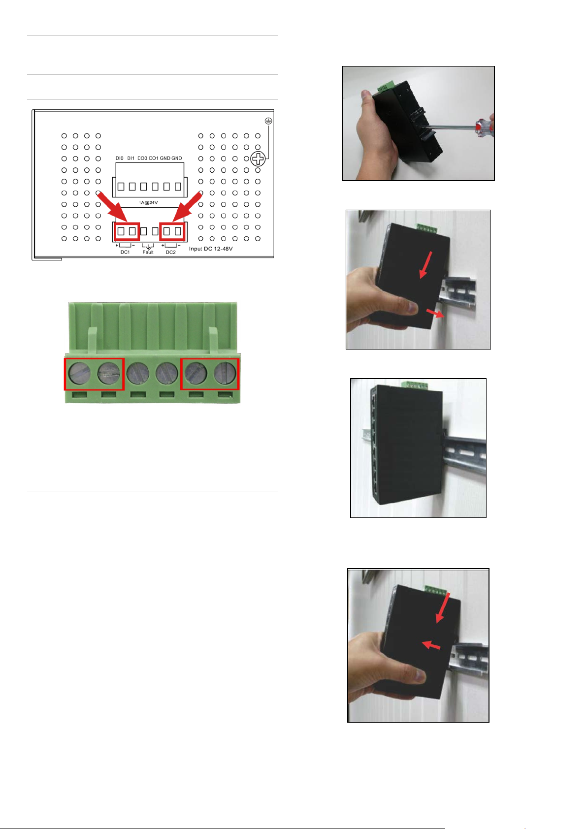
Wiring the power inputs
The upper panel of the industrial managed switch indicates a
DC inlet power socket and consists of one terminal block
connector within six contacts. Follow the steps below to insert
the power wire:
1. Insert the positive/negative DC power wires into contacts 1
and 2 for Power 1, or contacts 5 and 6 for Power 2.
NS3552-8P-2S-V2: DC 12~48 V
© 2019 United Technologies Corporation. P/N 1073550-EN • REV B • ISS 01FEB19
Interlogix is part of UTC Climate, Controls & Security, a unit of United Technologi es Corporat i on. All ri ghts reserved. Al l trademarks are the property
of their respective owners. Information in this document is subject to change without notice.
Page 2
1 2 3 4 5
6
V+
V1-
V2+
V2-
Power 1
Power 2
Caution: Do not plug a DC power connector into the device
while power is ON, as this will cause damage to the unit. This
is NOT a hot-swappable device.
Figure 2: NS3552-8P-2S-V2 upper panel
2. Tighten the wire-clamp screws to prevent the wires from
loosening.
1. Screw the DIN-rail on the industrial gigabit Ethernet
switch.
2. Place the bottom of DIN-rail lightly into the track.
Note: The wire gauge for the terminal block should be in the
range from 12 to 24 AWG.
Mounting
Note: Ensure that the industrial managed switch is mounted
vertically with the power connectors on the top and a minimum
of three inches above and below the switch to allow for proper
air flow. This device uses a convection flow of hot air which
rises and brings cold air in from the bottom and out of the top
of the device. Do not mount the switch horizontally as this does
not allow air to flow up into the device and will result in damage
to the switch. Do not tie DC1 to DC2. DC2 is for secondary
power redundancy. Do not plug DC power into the device while
the AC power cord is plugged in. This is not a hot-swappable
switch. Hot-swapping this device will result in damage.
3. Ensure that the DIN-rail is secured to the track.
To remove the industrial gigabit Ethernet switch from the track,
carefully pull out the bottom of the DIN-rail to remove it from
the track.
DIN-rail mounting installation
To replace the wall-mount application with DIN-rail application
on industrial gigabit Ethernet switch, refer to the following
figures to screw the DIN-rail on the industrial gigabit Ethern e t
switch.
To hang the industrial gigabit Ethernet switch, follow the steps
below:
2 / 6 P/N 1073550-EN • REV B • ISS 01FEB19
Page 3

Wall-mount plate mounting
To install the industria l gigab it Ethernet switch on the wall,
follow the steps below.
1. Remove the DIN-rail from the industrial gigabit Ethernet
switch. Loosen the screws to remove the DIN-rail.
2. Place the wall-mount plate on the rear panel of the
industrial gigabit Ethernet switch.
3. Use the screws to screw the wall-mount plate on the
industrial gigabit Ethernet switch.
4. Use the hook holes at the corners of the wall-mount plate
to hang the industrial gigabit Ethernet switch on the wall.
5. To remove the wall-mount plate, reverse the steps above.
3. Log in to the console. After the te rminal has been
connected to the device, power on the industrial managed
switch. The terminal display s “running testing procedures”.
When the following dia log box in Figure 4 below appears,
type the factory default user name "admin" and password
“admin”.
User name: admin
Password: admin
Terminal setup
To configure the system, connect a serial cable to a COM port
on a PC or notebook computer and to RJ45 type serial
(console) port of the i ndu stri al mana ged switch. The console
port of the industrial managed switch is DCE already so that
you can connect the console port directly through a computer
without the need of null modem.
Figure 3: Console connectivity
A terminal program is required to make the software connected
to the industrial managed switch. Windows' Hyper Terminal
program may be a good choice. The Hyper Terminal can be
accessed from the Start menu.
1. Click Start > Programs > Accessories > Hyper
Terminal.
2. When the following screen appears, ensure that the COM
port is configured as shown below. Click OK when finished
with configuration.
Figure 4: Console login screen
Note:
1. For security purposes, change and memorize the new
password after this first setup.
2. Only commands in lowercase letters are accepted in the
console interface.
Configuring the IP address
The industrial managed switch is shipped with the default IP
address shown below:
IP Address: 192.168.0.100
Subnet Mask: 255.255.255.0
To check the current IP address or modify a new IP address
for the industrial managed switch, use the following
procedures:
P/N 1073550-EN • REV B • ISS 01FEB19 3 / 6
Page 4

Display of the current IP Address
1. At the “#” prompt, type “show ip interface brief.”
2. The screen displays the current IP address as shown in
Figure 5 below.
Figure 5: IP information screen
Configuration of the IP address
3. At the “#” prompt, type the following command and press
Enter.
NS3552-8P-2S-V2# configure terminal
NS3552-8P-2S-V2(config)# interf ace vlan 1
NS3552-8P-2S-V2(config-if-vlan)# ip address
192.168.1.100 255.255.255. 0
The previous command applies the following settings for
the industrial managed switch.
IP Address: 192.168.1.100
Starting web management
The section describes how to start up the web management
function for the industrial man aged switch. Note that the
industrial managed switch is conf ig ured thr ou gh an Ether net
connection. Ensure that the manager computer is set to the
same IP subnet address.
For example, if the default IP address of the industrial
managed switch is 192.168.0.100, then the manager computer
should be set to 192.168.0.x (where x is a number between 1
and 254, except 100), and the default subnet mask is
255.255.255.0.
Figure 8: IP management diagram
Subnet Mask: 255.255.255.0
Figure 6: Configuring the IP address screen
4. Repeat step 1 to check if the IP address has changed.
Store the current switch configuration
5. At the “#” prompt, type the following command and press
Enter.
# copy running-config startup-config
Figure 7: Saving current configuration command screen
Logging in to the industrial managed switch
1. Use the Internet Explorer 11.0 or later web browser and
type the IP address http://192.168.0.100 (the fact ory default IP address) to access the web interface.
2. When the following dia log box appears, enter the default
user name “admin” and password “admin” (or the
password you have changed before) as shown in Figure 9
below.
Default IP Address: 192.168.0.100
Default User Name: admin
Default Password: admin
Figure 9: Login screen
If the IP is successfully configured, the industrial managed
switch applies the new IP address setting immediately. Access
the web interface of the industrial managed switch through the
new IP address.
3. After typing the password, the main screen appears as
shown in Figure 10 on page 5.
Note: If unfamiliar with the console command or the related
parameter, type “help” in the console to obtain the Help
description.
4 / 6 P/N 1073550-EN • REV B • ISS 01FEB19
Page 5

Figure 10: Main web interface screen
4. The switch menu on the left side of the web page permits
access to the commands and statistics provided by the
industrial managed switch.
2. Click the Save Configuration button.
Refer to the User Manual for further informat ion abou t using
the web management interface.
Note: For security purposes, change and memorize the new
password after this first setup.
Saving the configuration
The running configuration file is stored in the RAM of the
managed switch. In the current version, the running
configuration sequence of running-config can be saved from
the RAM to FLASH by executing the Save Startup Config
command. After doing this, the running configuration sequence
becomes the startup configuration file (i.e., the saved
configuration).
To save all applied changes and set the current configuration
as a startup configuration, the startup-c onfi gur at ion fil e is
loaded automatically across a system reboot.
1. Click System > Save Startup Config.
Resetting the switch to default
To reset the IP address to the default IP address
“192.168.0.100” and the user password to factory default mode
(default password is “admin”), press the hardware reset button
on the front panel for about 10 seconds. After the device is
rebooted, log in to the management web interface within the
same subnet of 192.168.0.xx and default password. Note that
all the previous setups are erased after the factory default
reset.
Figure 11: Reset button
P/N 1073550-EN • REV B • ISS 01FEB19 5 / 6
Page 6

North America
T
E
W
Latin America
T
E
Europe, Middle East, and Africa
W
Australia
E
W
Contact information
+1 855.286.8889
techsupport@interlogix.com
www.interlogix.com/support
+1 561-998-6114
latam@interlogix.com
Select Con tact Us at www.firesecurityproducts.com
security.tech.support@interlogix.com.au
www.utcfs.com.au/support
6 / 6 P/N 1073550-EN • REV B • ISS 01FEB19
 Loading...