

Page 1

NS3552-16P-2T-2S User
Manual
P/N 1073223-EN • REV A • ISS 21SEP16
Page 2

Copyright © 2016 United Technologies Corporation,
unsorted municipal waste in th e Europea n Unio n. See the produc t docume ntation f or spe cific batt ery
information. The battery is mar ked with this symbol, which may include lett er ing t o indicate cadmium
Interlogix is part of UTC Climate, Controls & Security, a unit of United Technologies Corporation.
All rights reserved.
Trademarks and
patents
Manufacturer Interlogix
Certification
FCC compliance Class A: This equipment has been tested and found to comply with the limits for a Class A digital
FCC conditions This device complies with Part 15 of the FCC Rules. Operation is subject to the following two
Trade names used in this document may be trademarks or registered trademarks of the
manufacturers or vendors of the respective products.
2955 Red Hill Avenue, Costa Mesa, CA 92626-5923, USA
Authorized EU manufacturing representative:
UTC Fire & Security B.V.
Kelvinstraat 7, 6003 DH Weert, The Netherlands
device, pursuant to part 15 of the FCC Rules. These limits are designed to provide reasonable
protection against harmful interference when the equipment is operated in a commercial
environment. This equipment generates, uses, and can radiate radio frequency energy and, if not
installed and used in accordance with the instruction manual, may cause harmful interference to
radio communications. Operation of this equipment in a residential area is likely to cause harmful
interference in which case the user will be required to correct the interference at his own expense.
conditions:
(1) This device may not cause harmful interference.
(2) This Device must accept any interference received, including interference that may cause
undesired operation.
ACMA
compliance
Canada This Class A digital apparatus complies with CAN ICES-003 (A)/NMB-3 (A).
European Union
directives
Contact
information
Notice! This is a Class A product. In a domestic environment this product may cause radio
interference in which case the user may be required to take a dequa te mea sure s.
Cet appareil numérique de la classe A est conforme à la norme CAN ICES-003 (A)/NMB-3 (A).
This product and - if applicable - the supplied accessories too are marked with "CE" and comply
therefore with the applicable harmonized European standards listed under the EMC Directive
2014/30/EU, the RoHS Directive 2011/65/EU.
2012/19/EU (WEEE directive): Products marked with this symbol cannot be disposed of as
unsorted municipal waste in the European Union. For proper recycling, return this product to your
local supplier upon the purchase of equivalent new equipment, or dispose of it at designated
collection points. For more informati on see: w ww.recyclethis.info.
2013/56/EU (battery directive): This product contains a battery that cannot be disposed of as
(Cd), lead (Pb), or mercury (Hg). For proper recycling, return the battery to your supplier or to a
designated collection point. For more information see:
For contact information, see www.interlogix.com
www.recyclethis.info.
Page 3

TABLE OF CONTENTS
1. INTRODUCTION .................................................................................................................... 8
1.1 Packet Contents ........................................................................................................................................... 8
1.2 Product Description ..................................................................................................................................... 9
1.3 How to Use This Manual ............................................................................................................................ 13
1.4 Product Features ........................................................................................................................................ 14
1.5 Product Specificatio n s .............................................................................................................................. 17
2. INSTALLATION ................................................................................................................... 22
2.1 Hardware Description ................................................................................................................................ 22
2.1.1 Physical Dimensions ........................................................................................................................................... 22
2.1.2 Front Panel .......................................................................................................................................................... 23
2.1.3 LED Indications ................................................................................................................................................... 25
2.1.4 Switch Upper Panel ............................................................................................................................................. 26
2.1.6 Wiring the Digital Input/Output ............................................................................................................................. 28
2.2 Installing the Industrial Managed Switch ................................................................................................. 30
2.2.1 Installation Steps.................................................................................................................................................. 30
2.2.2 DIN-rail Mounting ................................................................................................................................................. 32
2.2.3 Wall Mount Plate Mounting .................................................................................................................................. 34
2.3 Cabling ........................................................................................................................................................ 35
2.3.1 Installing the SFP Transceiver ............................................................................................................................. 36
2.3.2 Removing the SFP Transceiver ........................................................................................................................... 39
3. SWITCH MANAGEMENT .................................................................................................... 40
3.1 Requirements .............................................................................................................................................. 40
3.2 Management Access Overview ................................................................................................................. 41
3.3 CLI Mode Management .............................................................................................................................. 42
3.4 Web Management ....................................................................................................................................... 44
3.5 SNMP-based Network Management ......................................................................................................... 45
3.6 IFS Smart Discovery Utility ....................................................................................................................... 46
4. WEB CONFIGURATION ...................................................................................................... 48
NS3552-16P-2T-2S User Manual 1
Page 4

4.1 Main Web page ........................................................................................................................................... 51
4.2 System ......................................................................................................................................................... 53
4.2.1 System Information .............................................................................................................................................. 54
4.2.2 IP Configuration ................................................................................................................................................... 55
4.2.3 IP Status .............................................................................................................................................................. 57
4.2.4 Users Configuration ............................................................................................................................................. 57
4.2.5 Privilege Levels ................................................................................................................................................... 61
4.2.6 NTP Configuration ............................................................................................................................................... 63
4.2.7 Time Conf igur ati on .............................................................................................................................................. 64
4.2.8 UPnP ................................................................................................................................................................... 65
4.2.9 DHCP Relay ........................................................................................................................................................ 66
4.2.10 DHCP Relay Statistics ....................................................................................................................................... 68
4.2.11 CPU Load .......................................................................................................................................................... 70
4.2.12 System Log ........................................................................................................................................................ 71
4.2.13 Detailed Log ...................................................................................................................................................... 72
4.2.14 Remote Syslog .................................................................................................................................................. 73
4.2.15 SMTP Configuration .......................................................................................................................................... 74
4.2.16 Digital Input/Outpu t ............................................................................................................................................ 75
4.2.17 Fault Alarm ........................................................................................................................................................ 77
4.2.18 Web Firmware Upgrade ..................................................................................................................................... 78
4.2.19 TFTP Firmware Upgrade ................................................................................................................................... 79
4.2.20 Save Startup Config ........................................................................................................................................... 80
4.2.21 Configuration Download .................................................................................................................................... 80
4.2.22 Configuration Upload ......................................................................................................................................... 81
4.2.23 Configuration Activate ........................................................................................................................................ 81
4.2.24 Configuration Delete .......................................................................................................................................... 82
4.2.25 Image Select ...................................................................................................................................................... 82
4.2.26 Factory Default .................................................................................................................................................. 83
4.2.27 System Reboot .................................................................................................................................................. 84
4.3 Simple Network Management Protocol .................................................................................................... 86
4.3.1 SNMP Overview .................................................................................................................................................. 86
4.3.2 SNMP System Configuration ............................................................................................................................... 87
4.3.3 SNMP Trap Configuration .................................................................................................................................... 89
4.3.4 SNMP System Information .................................................................................................................................. 91
4.3.5 SNMPv3 Configuration ........................................................................................................................................ 92
4.3.5.1 SNMPv3 Communities .............................................................................................................................. 92
4.3.5.2 SNMPv3 Users .......................................................................................................................................... 93
4.3.5.3 SNMPv3 Groups ........................................................................................................................................ 94
4.3.5.4 SNMPv3 Views .......................................................................................................................................... 95
2 NS3552-16P-2T-2S User Manual
Page 5

4.3.5.5 SNMPv3 Access ........................................................................................................................................ 96
4.4 Port Management ....................................................................................................................................... 98
4.4.1 Port Configuration ................................................................................................................................................ 98
4.4.2 Port Statistics Overview ..................................................................................................................................... 100
4.4.3 Port Statistics Detail ........................................................................................................................................... 101
4.4.4 SFP Module Information .................................................................................................................................... 103
4.4.5 Port Mirror .......................................................................................................................................................... 104
4.5 Link Aggregation ...................................................................................................................................... 107
4.5.1 Static Aggregat ion .............................................................................................................................................. 109
4.5.2 LACP Configuration ........................................................................................................................................... 110
4.5.3 LACP System Status ......................................................................................................................................... 112
4.5.4 LACP Port Status ............................................................................................................................................... 113
4.5.5 LACP Port Statistics ........................................................................................................................................... 114
4.6 VLAN .......................................................................................................................................................... 115
4.6.1 VLAN Overview ................................................................................................................................................. 115
4.6.2 IEEE 802.1Q VLAN ........................................................................................................................................... 116
4.6.3 VLAN Port Configuration ................................................................................................................................... 119
4.6.4 VLAN Membership Status .................................................................................................................................. 126
4.6.5 VLAN Port Status ............................................................................................................................................... 127
4.6.6 Private VLAN ..................................................................................................................................................... 128
4.6.7 Port Isolation ...................................................................................................................................................... 130
4.6.8 VLAN setting example: ...................................................................................................................................... 132
4.6.8.1 Two Separate 802.1Q VLANs .................................................................................................................. 132
4.6.8.2 VLAN Trunking between two 802.1Q aware switches ............................................................................. 135
4.6.8.3 Port Isolate .............................................................................................................................................. 137
4.6.9 MAC-based VLAN ............................................................................................................................................. 138
4.6.10 Protocol-based VLAN ...................................................................................................................................... 141
4.6.11 Protocol-based VLAN Membership .................................................................................................................. 143
4.7 Spanning Tree Protocol ........................................................................................................................... 144
4.7.1 Theory ............................................................................................................................................................... 144
4.7.2 STP System Configuration ................................................................................................................................ 150
4.7.3 Bridge Status ..................................................................................................................................................... 153
4.7.4 CIST Port Configuration ..................................................................................................................................... 154
4.7.5 MSTI Priorities ................................................................................................................................................... 157
4.7.6 MSTI Configuration ............................................................................................................................................ 158
4.7.7 MSTI Ports Configuration .................................................................................................................................. 159
4.7.8 Port Status ......................................................................................................................................................... 161
4.7.9 Port Statistics ..................................................................................................................................................... 162
NS3552-16P-2T-2S User Manual 3
Page 6

4.8 Multicast .................................................................................................................................................... 163
4.8.1 IGMP Snooping ................................................................................................................................................. 163
4.8.2 Profile Table ....................................................................................................................................................... 167
4.8.3 Address Entry .................................................................................................................................................... 168
4.8.4 IGMP Snooping Configuration ........................................................................................................................... 169
4.8.5 IGMP Snooping VLAN Configuration ................................................................................................................. 171
4.8.6 IGMP Snooping Port Group Filtering ................................................................................................................. 173
4.8.7 IGMP Snooping Status ...................................................................................................................................... 174
4.8.8 IGMP Group Information .................................................................................................................................... 175
4.8.9 IGMPv3 Information ........................................................................................................................................... 176
4.8.10 MLD Snooping Configuration ........................................................................................................................... 177
4.8.11 MLD Snooping VLAN Configuration................................................................................................................. 178
4.8.12 MLD Snooping Port Group Filtering ................................................................................................................. 180
4.8.13 MLD Snooping Status ...................................................................................................................................... 181
4.8.14 MLD Group Information ................................................................................................................................... 182
4.8.15 MLDv2 Information .......................................................................................................................................... 183
4.8.16 MVR (Multicast VLAN Registration) ................................................................................................................. 184
4.8.17 MVR Status ...................................................................................................................................................... 187
4.8.18 MVR Groups Information ................................................................................................................................. 188
4.8.19 MVR SFM Information ..................................................................................................................................... 189
4.9 Quality of Service ..................................................................................................................................... 190
4.9.1 Understanding QoS ........................................................................................................................................... 190
4.9.2 Port Policing ...................................................................................................................................................... 191
4.9.3 Port Classification .............................................................................................................................................. 192
4.9.4 Port Scheduler ................................................................................................................................................... 194
4.9.5 Port Shaping ...................................................................................................................................................... 195
4.9.5.1 QoS Egress Port Schedule and Shapers ................................................................................................ 196
4.9.6 Port Tag Remarking ........................................................................................................................................... 198
4.9.6.1 QoS Egress Port Tag Remarking ............................................................................................................. 199
4.9.7 Port DSCP ......................................................................................................................................................... 200
4.9.8 DSCP-based QoS ............................................................................................................................................. 202
4.9.9 DSCP Translation .............................................................................................................................................. 203
4.9.10 DSCP Classification ......................................................................................................................................... 204
4.9.11 QoS Control List............................................................................................................................................... 205
4.9.11.1 QoS Control Entry Configuration ........................................................................................................... 207
4.9.12 QCL Status ...................................................................................................................................................... 209
4.9.13 Storm Control Configuration ............................................................................................................................ 211
4.9.14 QoS Statistics .................................................................................................................................................. 212
4.9.15 Voice VLAN Configuration ............................................................................................................................... 213
4 NS3552-16P-2T-2S User Manual
Page 7

4.9.16 Voice VLAN OUI Table ..................................................................................................................................... 215
4.10 Access Control List ................................................................................................................................ 216
4.10.1 Access Control List Status ............................................................................................................................... 216
4.10.2 Access Control List Configuration .................................................................................................................... 218
4.10.3 ACE Configuration ........................................................................................................................................... 220
4.10.4 ACL Ports Configuration .................................................................................................................................. 230
4.10.5 ACL Rate Limiter Configuration ....................................................................................................................... 232
4.11 Authentication ......................................................................................................................................... 233
4.11.1 Understanding IEEE 802.1X Port-based Authentication .................................................................................. 234
4.1 1.2 Authenti cation Configuration ............................................................................................................................ 238
4.11.3 Network Access Server Configuration .............................................................................................................. 239
4.11.4 Network Access Overview ............................................................................................................................... 250
4.11.5 Network Access Statistics ................................................................................................................................ 251
4.11.6 RADIUS ........................................................................................................................................................... 258
4.11.7 TACACS+ ........................................................................................................................................................ 260
4.11.8 RADIUS Overview ........................................................................................................................................... 261
4.11.9 RADIUS Details ............................................................................................................................................... 263
4.11.10 Windows Platform RADIUS Server Configuration .......................................................................................... 270
4.11.11 802.1X Client Configuration ........................................................................................................................... 275
4.12 Security ................................................................................................................................................... 278
4.12.1 Port Limit Control ............................................................................................................................................. 278
4.12.2 Access Management ....................................................................................................................................... 281
4.12.3 Access Management Statistics ........................................................................................................................ 282
4.12.4 HTTPs ............................................................................................................................................................. 283
4.12.5 SSH ................................................................................................................................................................. 284
4.12.6 Port Security Status ......................................................................................................................................... 285
4.12.7 Port Security Detail .......................................................................................................................................... 287
4.12.8 DHCP Snooping .............................................................................................................................................. 288
4.12.9 Snooping Table ................................................................................................................................................ 289
4.12.10 IP Source Guard Configuration ...................................................................................................................... 290
4.12.11 IP Source Guard Static Table ......................................................................................................................... 291
4.12.12 Dynamic IP Source Guard Table .................................................................................................................... 292
4.12.13 ARP Inspection .............................................................................................................................................. 293
4.12.14 ARP Inspection Stati c T able ........................................................................................................................... 294
4.12.15 Dynamic ARP Inspection Table ...................................................................................................................... 295
4.13 MAC Address Table ................................................................................................................................ 297
4.13.1 MAC Table Configuration ................................................................................................................................. 297
4.13.2 MAC Address Table Status .............................................................................................................................. 299
NS3552-16P-2T-2S User Manual 5
Page 8

4.14 LLDP ........................................................................................................................................................ 301
4.14.1 Link Layer Discovery Protocol ......................................................................................................................... 301
4.14.2 LLDP Configuration ......................................................................................................................................... 301
4.14.3 LLDP MED Configuration ................................................................................................................................ 304
4.14.4 LLDP-MED Neighbor ....................................................................................................................................... 311
4.14.5 Neighbor .......................................................................................................................................................... 315
4.14.6 Port Statistics ................................................................................................................................................... 316
4.15 Network Diagnostics .............................................................................................................................. 318
4.15.1 Ping ................................................................................................................................................................. 319
4.15.2 IPv6 Ping ......................................................................................................................................................... 320
4.15.3 Remote IP Ping Test ........................................................................................................................................ 321
4.15.4 Cable Diagnostics ............................................................................................................................................ 322
4.16 Power over Ethernet ............................................................................................................................. 324
4.16.1 Power over Ethernet Powered Device ............................................................................................................. 325
4.16.2 System Configuration ...................................................................................................................................... 325
4.16.3 Power Over Ethernet Configuration ................................................................................................................. 327
4.16.4 Port Sequential ................................................................................................................................................ 329
4.16.5 Port Configuration ............................................................................................................................................ 329
4.16.6 PoE Status ....................................................................................................................................................... 332
4.16.7 PoE Schedule .................................................................................................................................................. 334
4.16.8 LLDP PoE Neighbours ..................................................................................................................................... 336
4.17 Loop Protection ...................................................................................................................................... 338
4.17.1 Configuration ................................................................................................................................................... 338
4.17.2 Loop Protection Status..................................................................................................................................... 339
4.18 RMON ....................................................................................................................................................... 341
4.18.1 RMON Alarm Configuration ............................................................................................................................. 341
4.18.2 RMON Alarm Status......................................................................................................................................... 343
4.18.3 RMON Event Configuration ............................................................................................................................. 344
4.18.4 RMON Event Status......................................................................................................................................... 345
4.18.5 RMON History Configuration ........................................................................................................................... 346
4.18.6 RMON History Status....................................................................................................................................... 347
4.18.7 RMON Statistics Configuration ........................................................................................................................ 348
4.18.8 RMON Statistics Status .................................................................................................................................... 349
4.19 PTP .......................................................................................................................................................... 351
4.19.1 PTP Configuration ........................................................................................................................................... 351
4.19.2 PTP Status ....................................................................................................................................................... 355
4.20 Ring .......................................................................................................................................................... 357
6 NS3552-16P-2T-2S User Manual
Page 9

4.20.1 MEP Configuration........................................................................................................................................... 358
4.20.2 Detailed MEP Configuration ............................................................................................................................ 359
4.20.3 Ethernet Ring Protocol Switch ......................................................................................................................... 362
4.20.4 Ethernet Ring Protocol Switch Configuration ................................................................................................... 364
4.20.5 Ring Wizard ..................................................................................................................................................... 367
4.20.6 Ring Wizard Example: ..................................................................................................................................... 368
5. SWITCH OPERATION ....................................................................................................... 371
5.1 Address Table ........................................................................................................................................... 371
5.2 Learning .................................................................................................................................................... 371
5.3 Forwarding & Filtering ............................................................................................................................. 371
5.4 Store-and-Forward ................................................................................................................................... 371
5.5 Auto-Negotiation ...................................................................................................................................... 372
6. TROUBLESHOOTING ....................................................................................................... 373
APPENDIX A: Networking Connection ............................................................................... 374
A.1 Switch's Data RJ45 Pin Assignments - 1000Mbps, 1000BASE-T ........................................................ 374
A.2 10/100Mbps, 10/100BASE-TX .................................................................................................................. 374
APPENDIX B : GLOSSARY .................................................................................................. 376
NS3552-16P-2T-2S User Manual 7
Page 10

1. INTRODUCTION
Port 100/1000X SFP Managed
Model Name
Item
The Industrial
Managed Switch
RS232 to RJ45
Console Cable
NS3552-16P-2T-2S
“Industrial Managed Switch” is used as an alternative name for the above models in this user’s manual.
Industrial 16-Port 10/100/1000T 802.3at PoE + 2-Port 10/100/100T + 2Switch
1.1 Packet Contents
Open the box of the Indu stri al Managed Switch and carefully unpack it. The box should contain the following items:
Quick Installation
Guide
DIN Rail Kit
NS3552-16P-2T-2S
1
1
1
1
Wall Mounting Kit
SFP Dust Caps
RJ45 Dust Caps
If any of these are missing or damaged, please contact your dealer immediately; if possible, retain the carton including the
original packing material, and use them again to repack the product in case there is a need to return it to us for repair.
1
2
2
8 NS3552-16P-2T-2S User Manual
Page 11

1.2 Product Description
IFS Industrial Managed Switch is specially designed to build a full Gigabit backbone to transmit reliable and high speed data in
heavy industrial demanding en v ir onme nt s a nd forward data to remote network throu gh fiber optic. It comes with an IP30 rugged
case and redundant power sy s tem. Besides support for 40Gb p s sw itch fa br ic t o han dle extremely large amounts of video, v oice
and important data in a secure topology, the Industrial Managed Switch provides user-friendly but advanced IPv6/ IPv4
management interfaces and abundant L2/L4 switching functions. It is the best investment for expanding industrial business or
upgrading its network infrastructure.
Redundant Ring, Fast Recovery for Critical Network Appli ca tions
The Industrial M anaged S witch supports redundant ring te chnology and fea ture s strong, rapid self-recovery cap ability to p rev ent
interruptions and external intrusions. It incorporates advanced ITU-T G.8032 ERPS (Ethernet Ring Protection Switching)
technology, Spanning Tree Protocol (802.1s MSTP), and redundant power input system into customer’s industrial automation
network to enhance system reliability and uptime in harsh factory environments. In certain simple Ring network, the recovery
time of data link can be as fast as 20ms.
Environmentally Hardened Design
With IP30 aluminum industrial case protection, the Industrial Managed Switch provides a high level of immunity against
electromagnetic interference and heavy electrical surges which are usually found on plant floors or in curb side traffic control
cabinets. It also possesses an integrated power supply source with wide range of voltages for worldwide high availability
applications requiring dual or backup power inputs. Being able to operate under the temperature range from -40 to 75 degrees
C, the Industrial Managed Switch can be placed in almost any difficult environment.
Digital Input and Digital Output for External Alarm
The Industrial Managed Switch sup ports Digital Input and Digit al Output on its upper panel. The external alarm enables users to
use Digital Input to det ect external device’s status (such a s d oor intrusion detector), and send event al ar m to t he ad mi nis t r ators .
The Digital Output could be used to alarm the administrators if the Industrial Managed Switch port is link-down, link-up or
power-dead.
NS3552-16P-2T-2S User Manual 9
Page 12
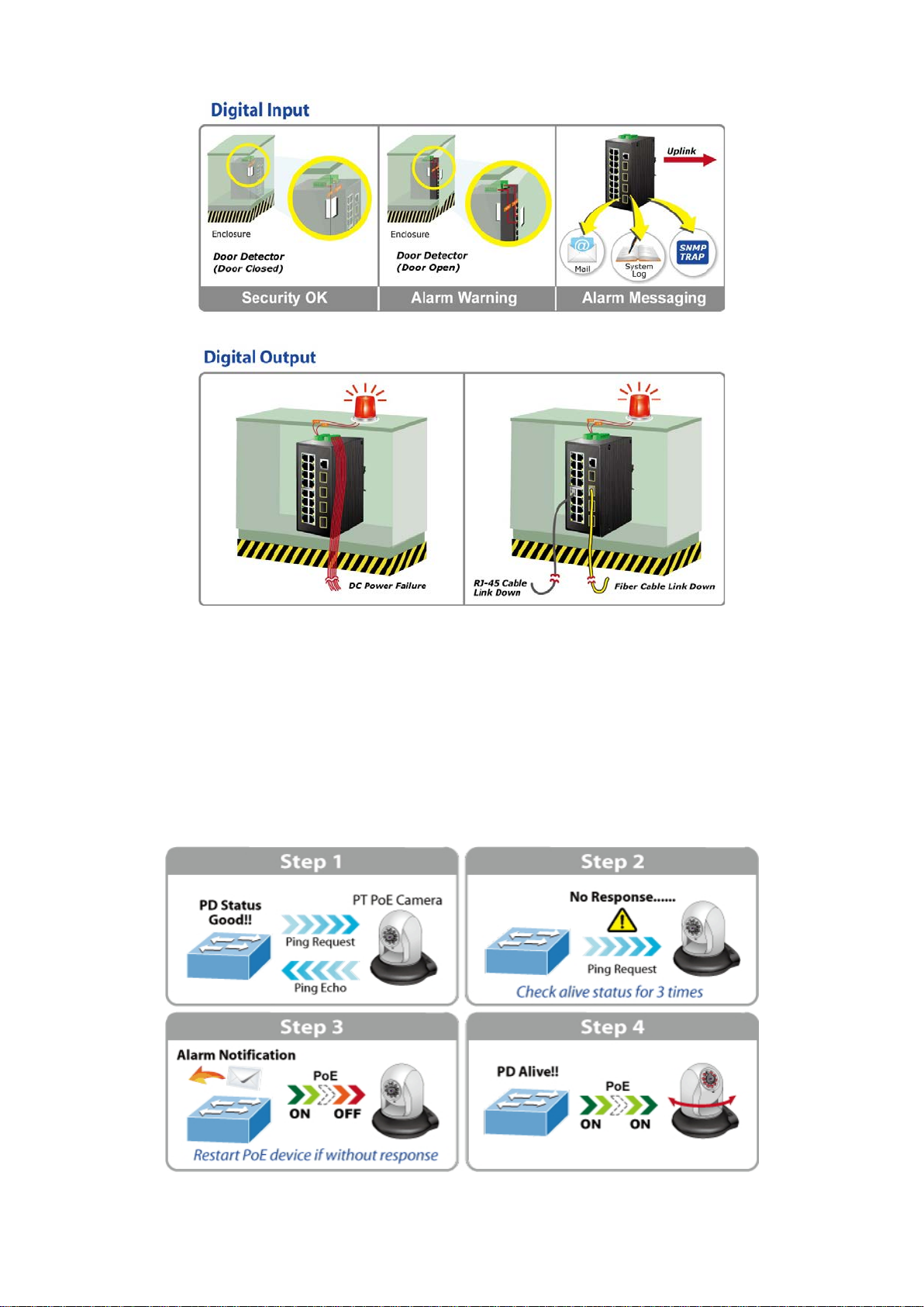
Intelligent Powered Device Alive Check
The Industrial Managed PoE Switch can be configured to monitor connected PD (Powered Device) status in real-time via ping
action. Once the PD stops working and responding, the Industrial Managed PoE Switch will recycle the PoE port power and
bring the PD back to work. It will greatly enhance the network reliability through the PoE port resetting the PD’s power source
and reduce administrator managem ent bur de n.
10 NS3552-16P-2T-2S User Manual
Page 13
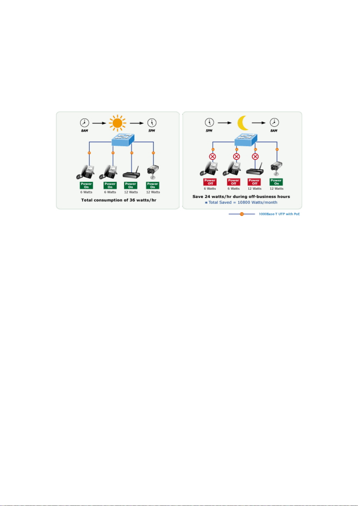
PoE Schedule for Energy Saving
Under the trend of energy saving worldwide and contributing to environment protection on the Earth, the Industrial Managed
PoE Switch can effectively control the power supply along with its capability of giving high watts power over Ethernet. The “PoE
schedule” function enables you to activate or inactivate PoE power feeding for each PoE port during specified time intervals,
which is a powerful function to help SMBs or enterprises save power and money.
Robust Layer2 Features
The Industrial Managed Switch can be programmed for advanced switch management function, such as dynamic port link
aggregation, Q-in-Q VLAN, Multiple Spanning Tree Protocol (MSTP), Layer 2/4 QoS, bandwidth control and IGMP/MLD
snooping. The Industrial Managed Switch allows the operation of a high-speed trunk combining multiple por ts.
IPv6/IPv4 Full-functionSecure Switch for Building Automation Networking
The Industrial Managed Switch is the ideal solution to fulfilling the demand of IPv6 management Gigabit Ethernet Switch,
especially in the Industrial hardened environment. It supports both IPv4 and IPv6 protocols, advanced Layer 2 to Layer 4 data
switching and redundancy, QoS traffic control, network access control and authentication, and Secure Management features to
protect customer’s industrial and building automation network connectivity with reliable switching recovery capability that is
suitable for implementing faul t tolerant and mesh network architectures.
IPv4 and IPv6 VLAN Routing for Secure and Flexible Management
The Industrial M anaged Sw itc h offers IPv4/IPv6 VLAN routi ng featu re w hich allow s to cross over dif fer ent V LANs and d if fer ent IP
addresses for the purpose of having a highly-secured, flexible management and simpler networking application.
User-friendly Secure Management
For efficient management, the Industrial Managed Switch is equipped with console, Web and SNMP management interfaces.
With the built-in web-based management interface, the Industrial Managed Switch offers an easy-to-use, platform independent
management and configuration facility. The Industrial Managed Switch supports SNMP and it can be managed via any
management software based on standard of SNMP v1 and v2 protocol. For reducing product learning time, the Industrial
Managed Switch offers Cisco-like command via Telnet or console port and customer doesn’t need to learn new command from
NS3552-16P-2T-2S User Manual 11
Page 14

these switches. Moreover, the Industrial Managed Switch offers remote secure management by supporting SSH, SSL and
SNMPv3 connection which can encrypt the packet content at each session.
Intelligent SFP Diagnosis Mechanism
The Industrial Managed Switch supports SFP-DDM (Digital Diagnostic Monitor) function that can easily monitor real-time
parameters of the SFP for network administrator, such as optical output power, optical input power, temperature, laser bias
current, and transceiver supply voltage.
Flexible and Extendable Solution
It features 100BASE-FX and 1000BASE-SX/LX SFP (Small Form-factor Pluggable) fiber-optic modules, meaning the
administrator now can flexibly choose the suitable SFP transceiver according to the transmission distance or the transmission
speed required to extend the network efficiently.
1588 Time Protocol for Industrial Compu ting Networks
The NS3552-16P-2T-2S is intended for telecom and carrier Ethernet applications, supporting MEF service delivery and timing
over packet solutions for IEEE 1588 and synchronous Ethernet.
12 NS3552-16P-2T-2S User Manual
Page 15

1.3 How to Use This Manual
This User’s Manual is structured as follows:
Section 2, INSTALLATION
The section explains the functi ons of the Industrial Managed Switch and how to physically install the Industrial
Managed Switch.
Section 3, SWITCH MANAGEMENT
The section contains the information about the software function of the Industrial Managed Switch.
Section 4, WEB CONFIGURATION
The section explains how to manage the Industrial Managed Switch by Web interf ace.
Section 5, SWITCH OPERATION
The chapter explains how to do the switch operation of the Industrial Manag ed Swit ch.
Section 6, TROUBLESHOOTING
The chapter explains how to do troubleshooting of the Industrial Managed Switch.
Appendix A
The section contains cab le inf or mat ion of the Industrial Managed Switc h.
Appendix B
The section contains glossary information of the Industrial Managed S witch.
NS3552-16P-2T-2S User Manual 13
Page 16

1.4 Product Features
Physical Port
10/100/1000BASE-T RJ45 copper
100/1000BASE-X mini-GBIC/SFP slots, SFP type auto detection
Console interface for basic management and setup of the NS3552-16P-2T-2S.
Power over Ethernet
Complies with IEEE 802.3at Power over Ethernet Plus/end-span PSE
Up to 8/16 IEEE 802.3af/802.3 at devi ces pow ered
Supports PoE power up to 15.4/36 watts for each PoE port
Auto detects powered device (PD)
Circuit protection prevents power interference betw een ports
Remote power feeding up to 100m
PoE management features
− Total PoE power budget control
− Per port PoE function enable/disable
− PoE admin-mode control
− PoE port power feeding priority
− Per PoE port power limit
− PD classification detection
Intelligent PoE features
− Temperature threshold control
− PoE usage threshold control
− PD alive check
− PoE schedule
Industrial Case and Installation
IP30 aluminum case protection
DIN-rail and wall-mount design
− Redundant power design
Supports Ethernet ESD protection for 6000V DC
-40 to 75 degrees C operating temperature
Digital Input and Digital Output
2 Digital Input (DI)
2 Digital Output (DO)
Integrates sensors into auto alarm system
Transfers alarm to IP network via email and SNMP trap
Layer 2 Features
High performance of Store-and-Forward architecture and ru nt/C RC filteri ng e liminat es erron eous p acke ts t o opt imize
14 NS3552-16P-2T-2S User Manual
Page 17

the network bandwidth
Storm Control supp or t
− Broadcast/Multicast/Unknown Unicast
Supports VLAN
− IEEE 802.1Q tagged VLAN
− Up to 255 VLANs groups, out of 4095 VLAN IDs
− Provider Bridging (VLAN Q-in-Q) support (IEEE 802.1ad)
− Private VLAN Edge (PVE)
− Protocol-based VLAN
− MAC-based VLAN
− Voice VLAN
Supports Spanning Tree Protocol
− IEEE 802.1D Spanning T r ee Protoc ol (STP)
− IEEE 802.1w Rapid Spanning Tree Protocol (RSTP)
− IEEE 802.1s Multiple Spanning Tree Protocol (MSTP) by VLAN
− BPDU Guard
Supports Link Aggregation
− 802.3 ad Link Aggregation Control Protocol (LACP)
− Cisco ether-channel (static trunk)
Provides port mirror (many-to-1)
Port mirroring of the incoming or outgoing traffic on a particular port
Loop protection to avoid broadcast loops
Supports E.R.P.S. (Ethernet Ring Protection Switching)
IEEE 1588 and Synchronous Ethernet network timing
Quality of Service
Ingress Shaper and Egress Rate Limit per port bandwidth control
8 priority queues on all switch ports
Traffic classification
- IEEE 802.1p CoS
- IP TOS/DSCP/IP Precedence
- IP TCP/UDP port number
- Typical networ k applic at io n
Strict priority and Weighted Round Robin (WRR) CoS policies
Supports QoS and In/Out bandwidth control on each port
Traffic-policing policies on the switch port
DSCP remarking
Multicast
Supports IPv4 IGMP snooping v1, v2 and v3
Supports IPv6 MLD snooping v1 and v2
Querier mode support
IGMP snooping port filtering
MLD snooping port filtering
MVR (Multicast VLAN Registration)
NS3552-16P-2T-2S User Manual 15
Page 18

Security
Authentication
− IEEE 802.1x Port-based/MAC-based network access authentication
− Built-in RADIUS client to cooperate with the RADIUS servers
− TACACS+ login users access authentication
− RADIUS/TACACS+ users access authentication
Access Control List
− IP-based Access Control List (ACL)
− MAC-based Access Control List
Source MAC/IP address binding
DHCP snooping to filter untrusted DHCP messages
Dy namic ARP Inspection discards ARP packets with invalid MAC address to IP address binding
IP Source Guard prevents IP spoofing attacks
Auto DoS rule to defend DoS attack
IP address access management to prevent unauthorized intruder
Layer 3 IP Routing Features
Supports static routes and route summarization
Management
IPv4 and IPv6 dual stack management
Switch Management Interfaces
- Console/Telnet Command Line Interface
- Web switch mana ge ment
- SNMP v1 and v2c switch management
- SSH/SSL and SNMP v3 secure access
IPv6 IP address/NTP/DNS management
Built-in Trivial File Transfer Protocol (TFTP) client
BOOTP and DHCP for IP address assignment
System Maintenance
− Firmware upload/download via HTTP/TFTP
− Reset button for system reboot or reset to factory default
− Dual Images
DHCP Relay and DHCP Option82
User Privilege levels contro l
NTP (Network Time Protocol)
Link Layer Discovery Protocol (LLDP) and LLDP-MED
SFP-DDM (Digit al Diagnostic Monitor)
Network Diagnostic
− ICMPv6/ICMPv4 Remote Ping
− Cable Diagnostic technology provides the mechanism to detect and report potential cabling issues
SMTP/Syslog remote alarm
Four RMON groups (history, statistics, alarms and events)
SNMP trap for interfacing Link Up and Link Down notification
System Log
IFS Smart Discovery Utili ty for deploy management
16 NS3552-16P-2T-2S User Manual
Page 19

1.5 Product Specifications
Model Name
NS3552-16P-2T-2S
Hardware Specificati ons
Copper Ports
18 10/100/1000BASE-T RJ45 Auto-MDI/MDI-X ports
Slots
Ports
Console
1 x RJ45 serial port (115200, 8, N, 1)
Architecture
Switch Fabric
second)
Address Table
8K entries, automatic source address learning and ageing
Buffer
Jumbo Frame
9Kbytes
> 5 sec: Factory Default
ESD Protection
6KV DC
Enclosure
Installation
DIN rail kit and wall-mount kit
Pin 1/2 for DI 0 & DI 1; Pin 3/4 for DO 0 & DO 1; Pin 5/6 for GND
AC
D x H)
NS3552-16P-2T-2S
SFP/mini-GBIC
PoE Injector
Switch
Throughput
(packet per
Shared Data
Flow Control
2 1000BASE-SX/LX/BX SFP interfaces (Port-19 to Port-20)
Compatible with 100BASE-FX SFP
16 ports with 802.3at/af PoE injector function with Port-1 to Port-16
Store-and-Forward
40Gbps/non-blocking
29.7Mpps@64Bytes
4Mbits
IEEE 802.3x pause frame for full-duplex
Back pressure for half-duplex
Reset Button
Connector
Alarm
DI and DO
Dimensions (W x
< 5 sec: System reboot
IP30 aluminum case
Removable 6-pin terminal block for power input
Pin 1/2 for Power 1; Pin 3/4 for fault alarm; Pin 5/6 for Power 2
Removable 6-pin terminal block for DI/DO interface
One relay output for power failure. Alarm Relay current carry ability: 1A @ 24V
2 Digital Input (DI): Level 0: -24V~2.1V (±0.1V)
Level 1: 2.1V~24V (±0.1V)
Input Load to 24V DC, 10mA max.
2 Digital Output (DO): Open collector to 24V DC, 100mA (max.)
84 x 107 x 152mm
NS3552-16P-2T-2S User Manual 17
Page 20

Weight
1533g
Power
Requirements
Consumption
Power Over Ethernet
PoE Standard
IEEE 802.3af/IEEE 802.3at Power over Ethernet/PSE
Supply Type
Output
Assignment
Budget
Class 2 PDs
Class 3 PDs
Class 4 PDs
Layer 2 Functions
Interfaces
Interface
Flow Control disable/enable
Port Status
Display each port’s speed duplex mode, link status, flow control status, auto
48~56V DC
Power
LED Indicator
PoE Power
PoE Power
349 watts/1190.83BTU (Full loading with PoE function)
System:
Power 1 (Green)
Power 2 (Green)
Fault Alarm (Green)
Ring (Green)
R.O. (Green)
End-span
Per Port 56V DC, 350mA . Max. 15.4 watts (IEEE 802.3af)
Per Port 56V DC, 590mA. Max. 30.8 watts (IEEE 802.3at)
Per 10/100/1000T
RJ45 Port:
LNK/ACT
(Green)
PoE-in-Use
(Orange)
Per SFP Interface:
LNK/ACT
(Green)
1000 (Orange)
Power Pin
PoE Power
Max. number of
Max. number of
Max. number of
Basic
Management
Secure
Management
1/2(+), 3/6(-)
320W maximum (depending on power input)
16
16
10
Web browser; remote Telnet; SNMPv 1, v2c; local console
SSH, SSL, SNMPv3
Port
Configuration
Port disable/enable
Auto-negotiation 10/100/1000Mbps full and half duplex mode selection
18 NS3552-16P-2T-2S User Manual
Page 21

negotiation status, trunk status.
Port Mirroring
Many to 1 monitor
Up to 255 VLAN groups, out of 4095 VLAN IDs
- DSCP/TOS field in IP packet
IGMP querier mode support
MLD querier mode support
List
Egress: 500Kb~1000Mbps
Layer 3 Functions
IP Interfaces
Max. 8 VLAN interfaces
Routing Table
Protocols
IPv6 software static routing
Standards Conformance
Compliance
VLAN
TX/RX/Both
802.1Q tagged-based VLAN, up to 255 VLAN groups
Q-in-Q tunneling
Private VLAN Edge (PVE)
MAC-based VLAN
Protocol-based VLAN
Voice VLAN
MVR (Multicast VLAN Registration)
Link Aggregation
QoS
IGMP Snooping
MLD Snooping
Access Control
Bandwidth
Control
IEEE 802.3ad LACP/static trunk
Supports 5 trunk groups with 2 ports for each trunk
Traffic classification bas ed, strict priority and WRR
8-level priority for switching
- Port number
- 802.1p priority
- 802.1Q VLAN tag
IGMP (v1/v2/v3) snooping, up to 255 multicast Groups
MLD (v1/v2) snooping, up to 255 multicast Gro ups
IP-based ACL/MAC-based ACL
Up to 256 entries
Per port bandwidth control
Ingress: 500Kb~1000Mbps
Max. 32 routing entries
Routing
Regulatory
Stability Testing
Standards
Compliance
IPv4 software static routing
FCC Part 15 Class A, CE
IEC60068-2-32 (free fall)
IEC60068-2-27 (shock)
IEC60068-2-6 (vibration)
IEEE 802.3 10BASE-T
IEEE 802.3u 100BASE-TX/100BASE-FX
IEEE 802.3z Gigabit SX/LX
NS3552-16P-2T-2S User Manual 19
Page 22

IEEE 802.3ab Gigabit 1000BASE-T
Environment
Relative Humidity: 5 ~ 95% (non-condensing)
IEEE 802.3x Flow Control and Back Pressure
IEEE 802.3ad Port Trunk with LACP
IEEE 802.1D Spanning Tree Protocol
IEEE 802.1w Rapid Spanning Tree Protocol
IEEE 802.1s Multiple Spanning Tree Protocol
IEEE 802.1p Class of Service
IEEE 802.1Q VLAN Tagging
IEEE 802.1ab LLDP
IEEE 802.1x Port Authentication Network Control
IEEE 802.3af Power over Ethernet
IEEE 802.3at Power over Ethernet
RFC 768 UDP
RFC 793 TFTP
RFC 791 IP
RFC 792 ICMP
RFC 2068 HTTP
RFC 1112 IGMP version 1
RFC 2236 IGMP version 2
RFC 3376 IGMP version 3
RFC 2710 MLD version 1
FRC 3810 MLD version 2
SNMP MIBs
Operating
RFC-1213 MIB-II
IF-MIB
RFC 1493 Bridge MIB
RFC 1643 Ethernet MIB
RFC 2863 Interface MIB
RFC 2665 Ether-Like MIB
RFC 2819 RMON MIB (Group 1, 2, 3 and 9)
RFC 2737 Entity MIB
RFC 2618 RADIUS Client MIB
RFC 2933 IGMP-STD-MIB
RFC 3411 SNMP-Frameworks-MIB
IEEE 802.1X PAE
LLDP
MAU-MIB
Temperature: -40 ~ 75 degrees C
Relative Humidity: 5 ~ 95% (non-condensing)
Storage
Temperature: -40 ~ 75 degrees C
20 NS3552-16P-2T-2S User Manual
Page 23

NS3552-16P-2T-2S User Manual 21
Page 24

2. INSTALLATION
2.1 Hardware Description
The Industrial Managed Switch provides three different running speeds – 10Mbps, 100Mbps and 1000Mbps and a utomat ical ly
distinguishes the speed of incoming connection.
This section describes the har dw are featur es of Industrial Managed Switch. For ea sier man agement a nd contr ol of the Industrial
Managed Switch, familiarize yourself with its display indicators and ports. Front panel illustrations in this chapter display the unit
LED indicators. Before connecting any network device to the Industrial Managed Switch, read this cha pter carefully.
2.1.1 Physical Dimensions
S3552-16P-2T-2S
NS3552-16P-2T-2S
Dimensions (W x D x H) : 84 x 107 x 152mm
22 NS3552-16P-2T-2S User Manual
Page 25

2.1.2 Front Panel
NS3552-16P-2T-2S
Figure 2-1: NS3552-16P-2T-2S Front Panel
■ Gigabit TP Interface
10/100/1000BASE-T Copper, RJ45 Twisted-pair: Up to 100 meters.
■ SFP Slot
NS3552-16P-2T-2S User Manual 23
Page 26

100/1000BASE-X mini-GBIC slot, SFP (Small-form Factor Pluggable) transceiver module: From 550 meters to 2km
Console interface is not available for the
Reset Button Pressed and Released
Function
(multi-mode fiber), up to 10/20/30/40/50/70 kilometers (single-mode fiber).
■ Console Port
The console port is an RJ45 port connector. It is an interface for connecting a terminal directly. Through the console port, it
provides rich diagnostic information including IP addre ss setti ng, factory reset, port management, link status and system
setting. Users can use the attached DB9 to RJ45 console cable in the package and connect to the console port on the
device. Af ter the con nec tio n, users can run any terminal emulation program (Hyper Terminal, ProComm Plus, Telix,
Winterm and so on) to enter the startup screen of the device.
NS3552-16P-2T-2S.
■ Reset button
On the upper left side of the front panel, the reset button is designed for rebooting the Industrial Industrial Managed Switch
without turning off and on the power. The following is the summary table of reset button functions:
NS3552-16P-2T-2S
Figure 2-8:
NS3552-16P-2T-2S Reset Button
< 5 sec: System Reboot Reboot the Industrial Managed Switch.
24 NS3552-16P-2T-2S User Manual
Page 27

> 5 sec: Factory Default
configuration. The Industrial Managed Switch will then reboot
192.168.0.254
2.1.3 LED Indications
NS3552-16P-2T-2S
LED Definition:
System
LED Color Function
Reset the Industrial Managed Switch to Factory Default
and load the default settings as shown below:
。 Default Username: admin
。 Default Password: admin
。 Default IP address: 192.168.0.100
。 Subnet mask: 255.255.255.0
。 Default Gateway:
P1 Green Indicates power 1 has power.
P2 Green Indicates power 2 has power.
Fault Green Indicates either power 1 or power 2 has no power.
Ring Green Lights to indicate that the ERPS Ring has been created successfully.
R.O. Green Lights to indicate that the Ring Owner has been enabled.
Per 10/100/1000BASE-T Port
LED Color Function
Lights
1000
Green
LNK/ACT
Blinks
Lights
10/100
Orange
LNK/ACT
Blinks
Indicates the port is running in 1000Mbps speed and successfully
established.
Indicates that the switch is actively sending or receiving data over that
port.
Indicates the port is running in 10/100Mbps speed and successfully
established.
Indicates that the switch is actively sending or receiving data over that
port.
Per SFP Interface
NS3552-16P-2T-2S User Manual 25
Page 28

LED Color Function
1000
Lights
Green
LNK/ACT
Blinks
Lights
100
Orange
LNK/ACT
Blinks
Indicates the port is running in 1000Mbps speed and successfully
established.
Indicates that the switch is actively sending or receiving data over that
port.
Indicates the port is running in 100Mbps speed and successfully
established.
Indicates that the switch is actively sending or receiving data over that
port.
2.1.4 Switch Upper Panel
The Upper Panel of the Industrial Managed Switch comes with a DC inlet power socket and one terminal block connec tor with
6 contacts.
1. Insert positive/negative DC power wires into contacts 1 and 2 for DC Power 1, or 5 and 6 for DC Power 2.
Figure 2-9: NS3552-16P-2T-2S Upper Panel
26 NS3552-16P-2T-2S User Manual
Page 29

2. Tighten the wire-clamp screws for preventing the wires from loosening.
1 2 3 4 5 6 DC 1
DC 2
Figure 2-20 6-Pin Terminal Block Power Wiring Input
Model Name Positive (+) Pin Negative (-) Pin Input Voltage
NS3552-16P-2T-2S Pin 1/5 Pin 2/6 DC 48~56V , AC 24V
If using PS48VDC240-DIN or PS 48VD C480-DIN you can adjust pot on front of Power Supply for 52Vdc.
1. The wire gauge for the terminal block should be in the range of 12 ~ 22 AWG@25 degress C.
2. When performing any of the pr oce dure s lik e ins er tin g t he w ires or tightening the wire-clamp screws,
make sure the power is OFF to prevent from getting an electric shock.
NS3552-16P-2T-2S User Manual 27
Page 30

2.1.5 Wiring the Fault Alarm Contact
The fault alarm contacts are in the middle (3 & 4) of the t ermin al block con nector as the p ictu re show s below. Inserting the wires,
the Industrial Managed Switch will dete ct t he fau lt st at us of the power failure, or port link failure (available for managed model).
The following illustration shows an application example for wiring the fault alarm contacts
Insert the wires into the fault alarm contacts
1. The wire gauge for the terminal block should be in the range of 12 ~ 24 AWG.
2. When performing any of the procedures like inserting the wires or tightening the wire-clamp screws,
make sure the power is OFF to prevent from getting an electric shock.
2.1.6 Wiring the Digital Input/Output
The 6-contact terminal block connector on the rear p a nel of NS3552-16P-2T-2S is used for Digital Input and Digital Output.
Please follow the steps below to insert wire.
1. The NS3552-16P-2T-2S offers two DI and DO groups. 1 and 2 are DI groups; 3 and 4 are DO groups; and 5 and 6 are
GND (ground).
28 NS3552-16P-2T-2S User Manual
Page 31

Figure 2-21 Wiring the Redundant Power Inputs
1 2 3 4 5
6
2. Tighten the wire-clamp screws for preventing the wires from loosening.
DI0 DI1 DO0 DO1 GND GND
Figure 2-22 6-pin Terminal Block for DI and DO Wiring Input
3. There are two Digital Input groups for you to monitor two different devices. The following topology shows how to wire DI0
and DI1.
Figure 2-23 Wires DI0 and DI1 to Open Detector
NS3552-16P-2T-2S User Manual 29
Page 32

4. There are two Digital Output groups for you to sense NS3552-16P-2T-2S port failure or power failure and issue a high or
low signal to external device.The following topology shows how to wire DO0 and DO1.
Figure 2-24 Wires DO0 and DO1 to Open Detector
2.2 Installing the Industrial Managed Switch
This section describes how to install your Industrial Mana ged Switch and make connections to the Industrial Managed
Switch. Please read the following topics and perform the procedures in the order being presented. To install your Industrial
Managed Switch on a desktop or shelf, simply complete the following steps.
In this paragraph, we will describe how to install the Industrial Managed Switch and the installation points attended to it.
2.2.1 Installation Steps
1. Unpack the Industrial Managed Switch
2. Check if the DIN-Rail is screwed on the Industrial Managed Switch or not. If the DIN-Rail is not screwed on the
Industrial Managed Switch, please refer to DIN-rail Mounting section for DIN-rail installation. If users want to
wall-mount the Industrial Managed Switch, please refer to the Wall Mount Plate Mounting section for wall-mount plate
installation.
3. To hang the Industrial Managed Switch on the DIN-rail track or wall.
4. Power on the Industrial Managed Switch. Please refer to the Wiring the Power Inputs section for knowing the
30 NS3552-16P-2T-2S User Manual
Page 33

information about how to wire the power. The power LED on the Industrial Managed Switch will light up. Please refer to
the LED Indicators section for indication of LED lights.
5. Prepare the twisted-pair, straight-through Category 5 cable for Ethernet connection.
6. Insert one side of RJ45 cable (category 5) into the Industrial Managed Switch Ethernet port (RJ45 port) while the
other side to the network device’s Ethernet port (RJ45 port), e.g., Switch PC or Server. The UTP port (RJ45) LED on the
Industrial Managed Switch will light up when the cable is connected with the network device. Please refer to the LED
Indicators section for LED light indication.
Make sure that the connected network devices support MDI/MDI-X. If it does not support,
use the crossover Category 5 cable.
7. When all connections are set and all LED lights show normal, the installation is completed.
NS3552-16P-2T-2S User Manual 31
Page 34

2.2.2 DIN-rail Mounting
This section describes how to install the Industrial Managed Switch. There are two methods to install the Industrial Managed
Switch -- DIN-rail mounting and wall-mount plate mounting. Please read the following topics and perform the procedures in the
order being presented.
Follow all the DIN-rail installation steps as shown in the example.
Step 1: Screw the DIN-rail on the Industrial Managed Switch.
Step 2: Lightly slide the DIN-rail into the track.
Step 3: Check whether the DIN-rail is tightly on the track.
32 NS3552-16P-2T-2S User Manual
Page 35

Please refer to the following procedures to remove the Industrial Managed Switch from the track.
Step 4: Lightly remove the DIN-rail from the track.
NS3552-16P-2T-2S User Manual 33
Page 36

2.2.3 Wall Mount Plate Mounting
To install the Industrial Managed Switch on the wall, please follow the instructions below.
Follow all the DIN-rail installation steps as shown in the example.
Step 1: Remove the DIN-rail from the Industrial Managed Switch. Use the screwdriver to loosen the screws to r emove the
DIN-rail.
Step 2: Place the wall-mount plate on the rear panel of the Industrial Managed Switch.
Step 3: Use the screwdriver to screw the wall mount plate on the Industrial Managed Switch.
Step 4: Use the hook holes at the corners of the wall mount plate to hang the Industrial Managed Switch on the wall.
Step 5: To remove the wall mount plate, reverse the steps above.
34 NS3552-16P-2T-2S User Manual
Page 37

2.3 Cabling
Port Type
Cable Type
Connector
10BASE-T
Cat3, 4, 5, 2-pair
RJ45
100BASE-TX
Cat5 UTP, 2-pair
RJ45
1000BASE-T
Cat5/5e/6 UTP, 2-pair
RJ45
50/125µm or 62.5/125µm multi-mode 9/125µm single-mode
LC
1000BASE-SX/LX
50/125µm or 62.5/125µm multi-mode 9/125µm single-mode
LC (multi/single mode)
10/100/1000BASE-T
All 10/100/1000BASE-T ports come with auto-negotiation capability. They automatically support 1000BASE-T,
100BASE-TX and 10BASE-T networks. Users only need to plug a working network device into one of the
10/100/1000BASE-T ports, and then turn on the Industrial Managed Switch. The port will automatically run in 10Mbps,
20Mbps, 100Mbps or 200Mbps and 1000Mbps or 2000Mbps after negotiating with the connected device.
100BASE-FX/1000BASE-SX/LX
The Industrial Managed Switch has four SFP interfaces that support 100/1000Mbps dual speed mode (optional
multi-mode/single-mode 100BASE-FX/1000BASE-SX/LX SFP module)
Cabling
Each 10/100/1000BASE-T port uses an RJ45 socket -- similar to phone jacks -- for connection of unshielded twisted-pair
cable (UTP). The IEEE 802.3/802.3u 802.3ab Fast/Gigabit Ethernet standard requires Category 5 UTP for 100Mbps
100BASE-TX. 10BASE-T networks can use Cat.3, 4, 5 or 1000BASE-T use 5/5e/6 UTP (see table below). Maximum
distance is 100 meters (328 feet). The 100BASE-FX/1000BASE-SX/LX SFP slot uses an LC connector with optional SFP
module. Please see tabl e belo w and know more about the cable specifications.
100BASE-FX
Any Ethernet devices like hubs and PCs can connect to the Industrial Managed Switch by using straight-through wires.
The two 10/100/1000Mbps ports are auto-MDI/MDI-X and can be used on straight-through or crossover cable.
(multi/single mode)
NS3552-16P-2T-2S User Manual 35
Page 38

2.3.1 Installing the SFP Transceiver
The sections describe how to insert an SFP transceiver into an SFP slot. The SFP transceivers are hot-pluggable and
hot-swappable. You can plug in and out the transceiver to/from any SFP port without having to power down the Industrial
Managed Switch as Figure 2-25 appears.
Figure 2-25: Plug in the SFP Transceiver
Approved IFS SFP Transceivers
IFS Industrial Managed Switch supports 100/1000 dual mode with both single mode and multi-mode SFP transceivers.
The following list of approved IFS SFP transceivers is correct at the time of publication:
Fast Ethernet Transceiver (100BASE-XX, SFP)
36 NS3552-16P-2T-2S User Manual
Page 39

Gigabit Ethernet Transceiver (1000BASE-X X SFP)
It is recommended to use IFS SFPs on the Industrial Managed Switch. If you insert an SFP
transceiver that is not supported, the Industrial Managed Switch might not recognize it.
Please choose the SFP transceiver which can be operated in the temperature range of -40~75
degrees C.
1000BASE-SX/LX:
Before connecting the other switches, workstation or media converter,
1. Make sure both sides of the S FP trans ceiv er are w ith the same media type, for example, 1000BASE-SX to 1000BASE-SX,
1000BASE-LX to 1000BASE-LX.
2. Check whether the fiber-op tic cabl e type mat ches the SFP transceiver model.
To connect to 1000BASE-SX SFP transceiver, use the multi-mode fiber cable -- with one side being the male duplex
LC connector type.
To connect to 1000BASE-LX SFP transceiver, use the single-mode fiber cable -- w ith one si de being the male duplex
LC connector type.
Connect the fiber cable
1. Attach the duplex LC connector on the network cable to the SFP transceiver.
2. Connect the other end of the cable to a device – switches with SFP installed, fiber NIC on a workstation or a media
converter.
3. Check the LNK/ACT LED of th e S FP slot on the front of the Industrial Managed Switch. Ensure that the SFP transceiver
is operating correctly.
NS3552-16P-2T-2S User Manual 37
Page 40

100BASE-FX:
Before connecting the other switches, workstation or media converter,
1. Make sure both sides of the SFP transceiver are with the same media type or WDM pair, for example, 100BASE-FX to
100BASE-FX, 100BASE-BX20-U to 100BASE-BX20-D.
2. Check whether the fiber-op tic cabl e type mat ches the SFP transceiver model.
To connect to SFP transceiver, use the multi-mode fiber cable -- with one side being the male duplex LC connector
type.
To connect to SFP transceiver, use the single-mode fiber cable -- with one side being the male duplex LC connector
type.
Connect the fiber cable
1. Attach the duplex LC connector on the network cable to the SFP transceiver.
2. Connect the other end of the cable to a device – switches with SFP installed, fiber NIC on a workstation or a media
converter.
3. Check the LNK/ACT LED of the SFP slot of the switch/converter. Ensure that the SFP transceiver is operating correctly.
4. Check the Link mode of the SFP port if the link fails. It can function with some fiber-NICs or media converters, and set the
Link mode to “100 Force” when needed.
38 NS3552-16P-2T-2S User Manual
Page 41

2.3.2 Removing the SFP Transceiver
1. Make sure there is no network activity by consulting or checking with the network administrator. Or through the
management interface of the swit ch/conver t er (if available) to disable the port in advance.
2. Remove the fiber optic cable gently.
3. Turn the lever of the SFP module to a horizontal position.
4. Pull out the module gently through the lever.
Figure 2-26: Pull out the SFP Transceiver Module
Never pull out the module without pulling the lever or the push bolts on the module. Directly pulling
out the module with force could damage the module and SFP module slot of the device.
NS3552-16P-2T-2S User Manual 39
Page 42

3. SWITCH MANAGEMENT
This chapter explains the methods that you can use to configure management access to the Industrial Managed Switch. It
describes the types of management applicati ons and the co m muni cat ion and ma nage men t protocols that deliver data between
your management device ( w or kstation or personal computer) and the system. It also contains in form ation about port connection
options.
This chapter covers the following topics:
Requirements
Management Access Overview
Remote Telnet Access
Web Management Access
SNMP Access
Standards, Protocols, and Related Reading
3.1 Requirements
Workstation running Windows XP/2003, Vista, Windo ws 7/8/10, MAC OS X, Linux, Fedora, Ubuntu or other
platform is compatible with TCP/IP protocols.
Workstation is installed with Ethernet NIC (Network Interface Card)
Serial Port (Terminal)
• The above PC comes with COM Port (DB9/RS232) or USB-to-RS232 converter
Ethernet Port
• Network cables -- Use standard network (UTP) cables with RJ45 connectors.
The above workstation is installed with Web browser and JAVA runtime environment Plug-in
It is recommended to use Internet Explore 8.0 or above to access Industrial Managed Switch.
40 NS3552-16P-2T-2S User Manual
Page 43

3.2 Management Access Overview
The Industrial Managed Switch gives you the flexibility to access and manage it using any or all of the following methods:
Remote Telnet Interface
Web browser Interface
An external SNMP-based network management application
The remote Telnet and Web browser interfaces are embedded in t he Industrial Managed Switch s of t w ar e a nd are available for
immediate use. Each of these management methods has their own advantages. Table 3-1 compar es the t hree ma nage me nt
methods.
Method Advantages Disadvantages
Console
Remote
Telnet
Web Browser
• No IP address or subnet needed
• Text-based
• Telnet functionality and HyperTerminal
built into Windows
95/98/NT/2000/ME/XP operating
systems
• ProcommPlus, putty, tera term
• Secure
• Text-based
• Telnet functionality built into Windows
XP/2003, Vista, Windows 7 operating
systems
• Can be accessed from any location
• Ideal for configuring the switch remotely
• Compatible with all popular browsers
• Can be accessed from any location
• Most visually appealing
• Must be near the switch or use dial-up
connection
• Not convenient for remote users
• Modem connection may prove to be unreliable
or slow
• Security can be compro mis ed (hac kers need
only know the IP address)
• Security can be compro mis ed (hac kers need
only know the IP address and subnet mask)
• May encounter lag times on poor connections
SNMP Agent
• Communicates with switch functions at
the MIB level
• Based on open st andar ds
Table 3-1: Management Methods Comparison
• Requires SNMP manager software
• Least visu ally appea lin g of all thr ee meth ods
• Some settings require calculations
• Security can be compro mis ed (hac kers need
only know the community name)
NS3552-16P-2T-2S User Manual 41
Page 44

3.3 CLI Mode Management
There are two ways for CLI mode management, one is remot e teln et and the other operated from consol e port. Remote telnet is
an IP-based protocol and console port is for user to operate the Industrial Managed Switch locally only; however, their
operations are the same.
The command line user interface is for performing system administration, such as displaying statistics or changing option
settings. When this method is used, you can access the Industrial Managed Switch remote telnet interface from personal
computer, or workstation in the same Ethernet environment as long as you know the current IP address of the Industrial
Managed Switch.
Direct Access
Direct access to the administration console is achieved by directly connecting a terminal or a PC equipped with a
terminal-emulation program (such as HyperTerminal, ProcommPlus, putty, tera term) to the Managed Switch con sol e (se rial)
port. When using this manage ment met hod, a straight DB9 RS-232 cable is required to connect the switch to the PC. After
making this connection, configure the terminal-emulation program to use the following parameters:
The default parameters are:
115200 bps baud rate
8 data bit s
No parity
1 stop bit
42 NS3552-16P-2T-2S User Manual
Page 45

You can change these settings, if desired, after you log on. This management method is often preferred because you can
remain connected and monitor the system during system reboots. Also, certain error messages are sent to the serial port,
regardless of the interface through which the associated action was initiated. A Macintosh or PC attachment can use any
terminal-emulation program for connect ing to th e ter minal serial port . A workstation at t achment under U NIX can use a n emu lator
Remote Telnet
In Windows system, you may click “Start” and then choose “Accessories”and “Command Prompt”. Please input “telnet
192.168.0.100” and press “enter’ from your keyboard. You will see the following screen appears as Figure 3-2 shows.
Figure 3-2: Remote Telnet Interface Main Screen of Industrial Managed Switch
NS3552-16P-2T-2S User Manual 43
Page 46

3.4 Web Management
The Industrial Managed Switch offers management features that allow users to manage the Industrial Managed Switch from
anywhere on the network through a standard browser such as Microsoft Internet Explorer. After you set up your IP address for
the Industrial Managed Switch, you can ac ces s the Industrial Managed Switch’s Web interface applications directly in your
Web browser by entering the IP address of the Industrial Managed Switch.
Figure 3-3: Web Management
You can then use your Web browser to list and manage the Industrial Managed Switch configuration par a meter s fr om one
central location; the Web Management requires Microsoft Internet Explorer 8.0 or later .
Figure 3-4: Web Main Screen of Industrial Managed Switch
44 NS3552-16P-2T-2S User Manual
Page 47

3.5 SNMP-based Network Management
You can use an external SNMP-based application to configure and manage the Industrial Managed Switch, such as SNMP
Network Manager, HP Openview Network Node Management (NNM) or What’s Up Gold. This management method requires
the SNMP agent on the Industrial Managed Switch and the SNM P Netw ork M anagement Station to use the same com munity
string. This management method, in fact, uses two community strings: the get community string and the set community
string.
If the SNMP Network Management Station only knows the set community string, it can read and write to the MIBs. However, if it
only knows the get community string, it can only read MIBs. The default gets and sets community strings for the Industrial
Managed Switch are public.
Figure 3-5: SNMP Management
NS3552-16P-2T-2S User Manual 45
Page 48

3.6 IFS Smart Discovery Utility
To easily list the Industrial Managed Switch in your Ethernet environment, the IFS Smart Discovery Utility from user’s manual
CD-ROM is an ideal solution. The following install instructions guide you to running the IFS Smart Discovery Util ity.
1. Open the IFS Smart Discovery Utility in administrator PC.
2. Run this utility and the following screen appears.
Figure 3-6: IFS Smart Discovery Utility Screen
If there are two LAN cards or above in the same administrator PC, choose a different LAN card
by using the “Select Adapter” tool.
3. Press the “Refresh” button for the currently connected devices in the discovery list as the screen is shown as follows.
Figure 3-7: IFS Smart Discovery Utility Screen
46 NS3552-16P-2T-2S User Manual
Page 49

1. This utility shows all the necessary information from the devices, such as MAC Address, Device Name, firmware version
and Device IP Subnet address. A new password, IP Subnet address and description can be assigned to the devices.
2. After setup is completed, press the “Update Dev ice ”, “Update Multi” or “Update All” button to take ef fe ct. The meanings
of the 3 buttons above are shown below:
Update Device: Use the current setting on one single device.
Update Multi: Use the current setting on choose multi-devices.
Update All: Use the current setting on whole devices in the list.
The same functions mentioned above also can be found in “Option” tools bar.
3. To click the “Control Packet Force Broadcast” function, it allows new setting value to be assigned to the Web Smart
Switch under a different IP subnet address.
4. Press the “Connect to Device” button and then the Web login screen appears in Figure 3-7.
5. Press the “Exit” button to shut down IFS Smart Discovery Utility.
NS3552-16P-2T-2S User Manual 47
Page 50

4. WEB CONFIGURATION
ets. The user has to
This section introduces the configuration and functions of the Web-based management.
About Web-based Management
The Industrial Managed Switch offers management feature s that allow users to manage the Industrial Managed Switch from
anywhere on the network through a standard browser such as Microsoft Internet Explorer.
The Web-based Management supports Internet Explorer 8.0. It is based on Java Applets with an aim to reducing network
bandwidth consumption, enha ncing access speed and pres e nt ing an easy viewing screen.
By default, IE7.0 or later version does not allow Java Applets to open sock
explicitly modify the browser setting to enable Java Applets to use network ports.
The Industrial Managed Switch can be configured through an Ethernet connection, making sure the manager PC must be set
on same the IP subnet address with the Industrial Managed Switch.
For example, the default IP address of the Industrial Managed Switch is 192.168.0.100, then the manager PC should be set
at 192.168.0.x (where x is a number between 1 and 254, except 100), and the default subnet mask is 255.255.255.0.
If you have changed the default IP address of the Industrial Managed Switch to 192.168.1.1 with subnet mask 255.255.255.0
via console, then the manager PC should be set at 192.168.1.x (where x is a number between 2 and 254) to do the related
configuration on manager PC.
Figure 4-1-1: Web Management
Logging on the Industrial Managed Switch
1. Use Internet Explorer 7.0 or above Web browser. Enter the factory-default IP address to access the Web interface. The
factory-default IP address is as follows:
48 NS3552-16P-2T-2S User Manual
Page 51

http://192.168.0.100
2. When the following login screen appears, please enter the default username "admin" with password “admin” (or the
username/password you have changed via console) to login the main screen of Industrial Managed Switch. The login
screen in Figure 4-1-2 appears.
Figure 4-1-2: Login Screen
Default User name: admin
Default Password: admin
After entering the username and password, the main screen appears as Figure 4-1-3.
NS3552-16P-2T-2S User Manual 49
Page 52

.
Figure 4-1-3: Default Main page
Now, you can use the Web management interfa ce to contin u e the sw itch manage ment or mana ge the Industrial Managed
Switch by Web interface. The Switch Menu on the left of the web page lets you access all the commands and statistics the
Industrial Managed Switch provides.
1. It is recommended to use Inter net Explore 8.0 or above to access Industrial Managed Switch
2. The changed IP address takes effect immediately aft er cl ic king on the Save button. From now
on, you need to use the new IP address to access the Internet.
3. For security reason, please change and memorize the new password after this first setup.
4. Only accept command in lowercase letter.
50 NS3552-16P-2T-2S User Manual
Page 53

4.1 Main Web page
The Industrial Managed Switch provides a Web-based browser interfac e f or configur ing and man aging it. This interface allows
you to access the Industrial Managed Switch using the Web browser of your choice. This chapter describes how to use the
Industrial Managed Switch’s Web browser interface to configure and manage it.
Main Functions Menu
Copper Port Link Status
SFP Port Link Status
Help Button
Figure 4-1-4: Main page
Panel Display
The web agent displays an image of the Industrial Managed Switch’s ports. The Mode can be set to display different
information for the ports, including Link up or Link down. Clicking on the image of a port opens the Port Statistics page.
The port states are illustrated as follows:
Main Screen
NS3552-16P-2T-2S User Manual 51
Page 54

State Disabled Down Link
RJ45 Ports
SFP Ports
Main Menu
Using the onboard web agent , you can define system parame ters, man age a nd c ont ro l th e Industrial Managed Switch, and al l
its ports, or monitor network co nditi ons . Via the Web-Management, the administrator can set up the Industrial Managed
Switch by selecting the functions those listed in the Main Function. The screen in Figure 4-1-5 appears.
Figure 4-1-5: Industrial Managed Switch Main Functions Menu
52 NS3552-16P-2T-2S User Manual
 Loading...