

Page 1
NS3552-16P-2T-2S Quick Installation Guide
Figure 1: NS3552-16P-2T-2S Industrial L2+ Multi-port Full Gigabit
Managed Ethernet Switch
1. Package Contents
Thank you for purchasing IFS L2+ Industrial Managed Switch,
NS3552-16P. The descriptions of this model are as follows:
Industrial 16-Port 10/100/1000T 802.3at PoE +
2-Port 10/100/100T
+ 2-Port 100/1000X SFP Managed Switch
“Industrial Managed Switch” mentioned in this Quick
Installation Guide refers to the above seven models.
Open the box of the Industrial Managed Switch and carefully
unpack it. The box should contain the following items:
2. Requirements
The Industrial Managed Switch provides remote login interface
for management purposes. The following equipment is
necessary for further management:
Workstation is installed with Ethernet NIC (Network
Interface Card)
Choice of Internet browsers includes Windows XP/2003,
Vista, Windows 7, Windows 8, Windows 10, MAC OS X,
Linux, Fedora, Ubuntu or other platforms compatible with
TCP/IP protocols.
The above workstation is installed with Web browser
and JAVA runtime environment plug-in.
Ethernet Port connection
Use standard network (UTP) cables with RJ45
connectors.
Note: It is recommended to use Internet Explorer 8.0 or above
to access the Industrial Managed Switch.
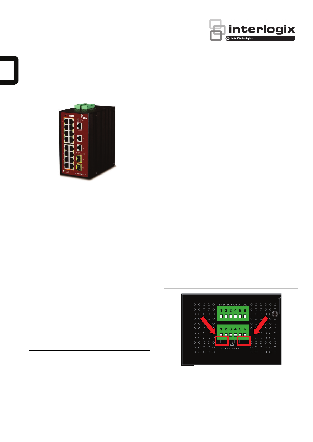
3. Wiring the Power Inputs
The Upper Panel of the Industrial Managed Switch indicates
a DC inlet power socket and consists of one terminal block
connector within 6 contacts. Please follow the steps below to
insert the power wire.
1. Insert positive/negative DC power wires into contacts 1
and 2 for Power 1, or 5, and 6 for Power 2.
NS3552-16P-2T-2S : DC 48~56V
The Industrial Managed Switch x 1
Quick Installation Guide x 1
DIN Rail Kit x 1
Wall Mounting Kit x 1
DB9 to RJ45 Interface RS232 Console Cable x 1
Dust Cap (Please refer to the table below)
RJ45 Dust Cap SFP Dust Cap
NS3552-16P-2T-2S 19 2
If any of these are missing or damaged, please contact your
dealer immediately. If possible, retain the carton including the
original packing materials to enable you to repack the product
in case there is a need to return it to us for repair.
© 2016 United Technologies Corporation. P/N 1073222-EN • REV A • ISS 21SEP16
Interlogix is part of UTC Climate, Controls & Security, a unit of United Technologies Corporation. All rights reserved.
Figure 2: NS3552-16P Upper Panel
2. Tighten the wire-clamp screws to prevent the wires from
loosening.
Page 2
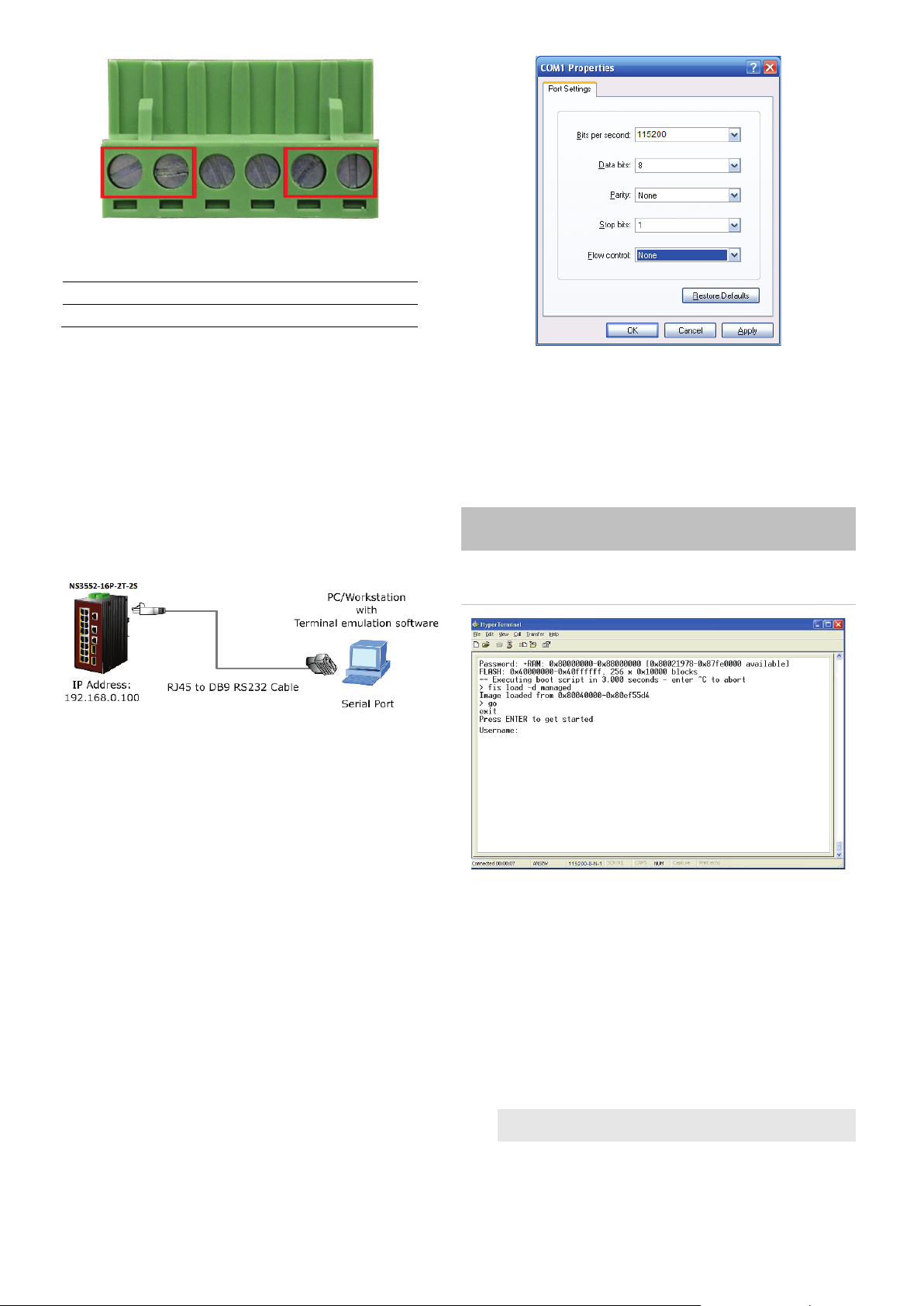
1 2 3 4 5 6 Power 1
Power 2
Positive (+) Pin Negative (-) Pin
NS3552-16P Pin 1/5 Pin 2/6
Note: The wire gauge for the terminal block should be in the
range from 12 to 24 AWG.
4. Terminal Setup
To configure the system, connect a serial cable to a COM port
on a PC or notebook computer and to RJ45 type serial
(console) port of the Managed Industrial Switch. The console
port of the Industrial Managed Switch is DCE already so that
you can connect the console port directly through PC without
the need of null modem.
3. Log on to the Console
Once the terminal has been connected to the device, power on
the NS3552-16P-2T-2S Switch and the terminal will display
“running testing procedures”.
When the following dialog box shown in Figure 3 appears,
please enter the factory default user name "admin" and
password “admin”.
User name: admin
Password: admin
Figure 3: Console Login screen
A terminal program is required to make the software connected
to the NS3552-16P-2T-2S Switch. Windows' Hyper Terminal
program may be a good choice. The Hyper Terminal can be
accessed from the Start menu.
1. Click START, then Programs, Accessories and then
Hyper Terminal.
2. When the following screen appears, make sure that the
COM port should be configured as:
♦ Baud: 115200
♦ Parity: None
♦ Data bits: 8
♦ Stop bits: 1
♦ Flow control: None
Note:
1. For security reason, please change and memorize the
new password after this first setup.
2. Only commands in lowercase letters are accepted in
the console interface.
6. Configuring IP address
The Industrial Managed Switch is shipped with default IP
address shown below:
IP Address: 192.168.0.100
Subnet Mask: 255.255.255.0
To check the current IP address or modify a new IP address
for the Switch, please use the procedure as follows:
2 / 4 P/N 1073222-EN • REV A • ISS 21SEP16
Page 3

Display of the current IP Address
1. At the “#” prompt, enter “show ip interface brief”.
2. The screen displays the current IP address shown in
Figure 4.
Figure 4: IP Information Screen
Configuration of the IP Address
3. At the “#” prompt, enter the following command and press
<Enter> as shown in Figure 5.
NS3552-16P-2T-2S# configure terminal
NS3552-16P-2T-2S (config)# interface vlan 1
NS3552-16P-2T-2S (config-if-vlan)# ip address 192.168.1.100
255.255.255.0
The previous command would apply the following settings
for the Industrial Managed Switch.
IP Address: 192.168.1.100
Subnet Mask: 255.255.255.0
Figure 5: Configuring IP Address Screen
Figure 6: Saving Current Configuration Command Screen
If the IP is successfully configured, the Industrial Managed
Switch will apply the new IP address setting immediately. You
can access the Web interface of the Industrial Managed Switch
through the new IP address.
Note: If you are not familiar with the console command or the
related parameter, enter “help” anytime in console to get the
help description.
7. Starting Web Management
The following shows how to start up the Web Management of
the Industrial Managed Switch. Note the Industrial Managed
Switch is configured through an Ethernet connection. Please
make sure the manager PC must be set to the same IP subnet
address.
For example, the default IP address of the Industrial Managed
Switch is 192.168.0.100, then the manager PC should be set
to 192.168.0.x (where x is a number between 1 and 254,
except 100), and the default subnet mask is 255.255.255.0.
4. Repeat step 1 to check if the IP address has changed.
Store the current switch configuration
5. At the “#” prompt, enter the following command and press
<Enter>.
# copy running-config startup-config
Figure 7: IP Management Diagram
Logging in to the NS3552-16P Switch
1. Use Internet Explorer 8.0 or above for Web browser and
enter IP address http://192.168.0.100 (the factory-default
IP address) to access the Web interface.
2. When the following dialog box appears, please enter the
default user name “admin” and password “admin” (or the
password you have changed before) as shown in Figure 8.
Default IP Address: 192.168.0.100
Default User Name: admin
Default Password: admin
P/N 1073222-EN • REV A • ISS 21SEP16 3 / 4
Page 4

Figure 8: Login Screen
3. After entering the password, the main screen appears as
shown in Figure 9.
Figure 9: Web Main Scree of Industrial Managed Switch
Note: For security reason, please change and memorize the
new password after this first setup.
8. Resetting the Switch to Default
To reset the IP address to the default IP Address
“192.168.0.100” and the user password to factory default
mode (default password is admin), press the hardware reset
button on the front panel for about 10 seconds. After the device
is rebooted, you can login the management Web interface
within the same subnet of 192.168.0.xx and default password.
Be noted that all the previous setups will be disappeared after
the factory default reset is made.
Figure 10: NS3552-16P Reset Button.
4. The Switch Menu on the left of the Web page lets you
access all the functions and status the Industrial Managed
Switch provides.
Now you can use the Web management interface to continue
the Switch management. Please refer to the user manual for
more.
9. Customer Support
Thank you for purchasing IFS products. You can browse our
online FAQ resource on IFS web site first to check if it could
solve your issue. If you need more support information, please
contact IFS switch support team.
Look under transmission.
IFS online FAQ:
http://www.Interlogix.com/support
Switch support team mail address:
http://www.Interlogix.com/support
4 / 4 P/N 1073222-EN • REV A • ISS 21SEP16
 Loading...