

Page 1

IFS NS3550-8T-2S
User Manual
P/N 1072687 • REV B • ISS 24JUN14
Page 2

Copyright © 2014 United Technologies Corporation
r
Interlogix is part of UTC Building & Industrial Systems, a unit of United
Technologies Corporation. All rights reserved.
User’s Manual of NS3550-8T-2S
Trademarks and
patents
The IFS NS3550-8T-2S name and logo are trademarks of United
Technologies.
Other trade names used in this document may be trademarks or registered
trademarks of the manufacturers or vendors of the respective products.
Manufacture
UTC Building & Industrial Systems, Inc.
2955 Red Hill Avenue
Costa Mesa, CA 92626-5923, USA
Authorized EU manufacturing representative:
UTC Climate Controls & Security B.V.,
Kelvinstraat 7, 6003 DH Weert, Netherlands
Intended use
Use this product only for the purpose it was designed for; refer to the data
sheet and user documentation for details. For the latest product information,
contact your local supplier or visit us online at www.interlogix.com.
Certification
N4131
FCC compliance
This equipment has been tested and found to comply with the limits for a
Class A digital device, pursuant to part 15 of the FCC Rules. These limits are
designed to provide reasonable protection against harmful interference
when the equipment is operated in a commercial environment. This
equipment generates, uses, and can radiate radio frequency energy and, if
not installed and used in accordance with the instruction manual, may cause
harmful interference to radio communications.
You are cautioned that any changes or modifications not expressly
approved by the party responsible for compliance could void the user's
authority to operate the equipment.
ACMA compliance Notice! This is a Class A product. In a domestic environment this product
may cause radio interference in which case the user may be required to take
adequate measures.
Canada
This Class A digital apparatus complies with Canadian ICES-003.
Cet appareil numérique de la classe A est conforme á la norme NMB-003du
Canada.
European Union
directives
2004/108/EC (EMC Directive): Hereby, UTC Building & Industrial Systems,
Inc. declares that this device is in compliance with the essential
requirements and other relevant provisions of Directive 2004/108/EC.
Contact Information For contact information, see www.interlogix.com
www.utcfssecurityproducts.eu
.
or
2
Page 3

User’s Manual of NS3550-8T-2S
TABLE OF CONTENTS
1. INTRODUCTION..................................................................................................................15
1.1 Packet Contents .........................................................................................................................................15
1.2 Product Description...................................................................................................................................16
1.3 How to Use This Manual............................................................................................................................17
1.4 Product Features........................................................................................................................................18
1.5 Product Specifications ..............................................................................................................................21
2. INSTALLATION ...................................................................................................................23
2.1 Hardware Description................................................................................................................................23
2.1.1 Physical Dimensions ...........................................................................................................................................23
2.1.2 Front Panel ..........................................................................................................................................................24
2.1.3 LED Indicators .....................................................................................................................................................25
2.1.4 Switch Upper Panel .............................................................................................................................................26
2.2 Installing Industrial Managed Switch.......................................................................................................27
2.2.1 Installation Steps..................................................................................................................................................27
2.2.2 DIN-Rail Mounting ...............................................................................................................................................28
2.2.3 Wall Mount Plate Mounting..................................................................................................................................30
2.3 Wiring the Power Inputs ............................................................................................................................31
2.4 Wiring the Fault Alarm Contact.................................................................................................................31
2.5 Cabling ........................................................................................................................................................31
2.5.1 Installing the SFP Transceiver.............................................................................................................................33
2.5.2 Removing the Module..........................................................................................................................................34
3. SWITCH MANAGEMENT.................................................................................................... 36
3.1 Requirements..............................................................................................................................................36
3.2 Management Access Overview.................................................................................................................37
3.3 Remote Telnet.............................................................................................................................................38
3.4 Web Management.......................................................................................................................................39
3.5 SNMP-Based Network Management.........................................................................................................40
4. WEB CONFIGURATION
4.1 Main Web Page...........................................................................................................................................44
4.2 System.........................................................................................................................................................46
4.2.1 System Information..............................................................................................................................................47
4.2.2 IP Configuration...................................................................................................................................................47
4.2.3 IPv6 Configuration ...............................................................................................................................................48
4.2.4 Users Configuration .............................................................................................................................................49
4.2.5 Privilege Levels ...................................................................................................................................................51
4.2.6 NTP Configuration ...............................................................................................................................................54
4.2.7 UPnP ...................................................................................................................................................................54
4.2.8 DHCP Relay ........................................................................................................................................................56
4.2.9 DHCP Relay Statistics .........................................................................................................................................57
4.2.10 CPU Load ..........................................................................................................................................................59
4.2.11 System Log ........................................................................................................................................................60
4.2.12 Detailed Log ......................................................................................................................................................60
4.2.13 Remote Syslog ..................................................................................................................................................62
4.2.14 SMTP Configuration ..........................................................................................................................................63
4.2.15 EEE Power Reduction .......................................................................................................................................64
4.2.16 Web Firmware Upgrade.....................................................................................................................................65
4.2.17 TFTP Firmware Upgrade ...................................................................................................................................65
4.2.18 Configuration Backup ........................................................................................................................................66
4.2.19 Configuration Upload.........................................................................................................................................68
4.2.20 Image Select......................................................................................................................................................69
4.2.21 Factory Default ..................................................................................................................................................71
......................................................................................................41
3
Page 4

User’s Manual of NS3550-8T-2S
4.2.22 System Reboot ..................................................................................................................................................72
4.2.23 Daylight Saving..................................................................................................................................................73
4.3 Simple Network Management Protocol....................................................................................................75
4.3.1 SNMP Overview ..................................................................................................................................................75
4.3.2 SNMP System Configuration ...............................................................................................................................75
4.3.3 SNMP System Information ..................................................................................................................................78
4.3.4 SNMPv3 Configuration ........................................................................................................................................79
4.3.4.1 SNMPv3 Communities ..............................................................................................................................79
4.3.4.2 SNMPv3 Users..........................................................................................................................................80
4.3.4.3 SNMPv3 Groups........................................................................................................................................81
4.3.4.4 SNMPv3 Views..........................................................................................................................................81
4.3.4.5 SNMPv3 Access........................................................................................................................................82
4.4 Port Management .......................................................................................................................................83
4.4.1 Port Configuration................................................................................................................................................83
4.4.2 Port Statistics Overview.......................................................................................................................................84
4.4.3 Port Statistics Detail.............................................................................................................................................86
4.4.4 SFP Information...................................................................................................................................................87
4.4.5 Port Mirror............................................................................................................................................................89
4.5 Link Aggregation........................................................................................................................................91
4.5.1 Static Aggregation................................................................................................................................................92
4.5.2 LACP Configuration.............................................................................................................................................94
4.5.3 LACP System Status ...........................................................................................................................................95
4.5.4 LACP Port Status.................................................................................................................................................95
4.5.5 LACP Port Statistics.............................................................................................................................................96
4.6 VLAN............................................................................................................................................................98
4.6.1 VLAN Overview ...................................................................................................................................................98
4.6.2 IEEE 802.1Q VLAN .............................................................................................................................................98
4.6.3 VLAN Basic Information.....................................................................................................................................100
4.6.4 VLAN Port Configuration ...................................................................................................................................101
4.6.5 VLAN Membership ............................................................................................................................................105
4.6.6 VLAN Membership Status..................................................................................................................................106
4.6.7 VLAN Port Status...............................................................................................................................................107
4.6.8 Private VLAN .....................................................................................................................................................107
4.6.9 Port Isolation......................................................................................................................................................109
4.6.10 VLAN setting example: .................................................................................................................................... 111
4.6.10.1 Two separate 802.1Q VLAN.................................................................................................................. 111
4.6.10.2 VLAN Trunking between two 802.1Q aware Switch .............................................................................. 114
4.6.10.3 Port Isolate ............................................................................................................................................ 116
4.6.11 MAC-based VLAN............................................................................................................................................ 116
4.6.12 MAC-based VLAN Status ................................................................................................................................ 118
4.6.13 Protocol-based VLAN ...................................................................................................................................... 11 9
4.6.14 Protocol-based VLAN Mambership .................................................................................................................121
4.7 Spanning Tree Protocol...........................................................................................................................121
4.7.1 Theory ...............................................................................................................................................................121
4.7.2 STP System Configuration ................................................................................................................................127
4.7.3 Bridge Status .....................................................................................................................................................128
4.7.4 CIST Port Configuration.....................................................................................................................................130
4.7.5 MSTI Priorities ...................................................................................................................................................133
4.7.6 MSTI Configuration............................................................................................................................................134
4.7.7 MSTI Ports Configuration ..................................................................................................................................136
4.7.8 Port Status.........................................................................................................................................................137
4.7.9 Port Statistics.....................................................................................................................................................138
4.8 Multicast....................................................................................................................................................139
4.8.1 IGMP Snooping .................................................................................................................................................139
4.8.2 IGMP Snooping Configuration ...........................................................................................................................143
4.8.3 IGMP Snooping VLAN Configuration.................................................................................................................144
4.8.4 IGMP Snooping Port Group Filtering .................................................................................................................146
4.8.5 IGMP Snooping Status ......................................................................................................................................147
4.8.6 IGMP Group Information....................................................................................................................................147
4.8.7 IGMPv3 Information...........................................................................................................................................149
4.8.8 MLD Snooping Configuration.............................................................................................................................149
4.8.9 MLD Snooping VLAN Configuration ..................................................................................................................151
4.8.10 MLD Snooping Port Group Filtering................................................................................................................. 152
4.8.11 MLD Snooping Status ......................................................................................................................................153
4.8.12 MLD Groups Information .................................................................................................................................153
4.8.13 MLDv2 Information ..........................................................................................................................................155
4
Page 5

User’s Manual of NS3550-8T-2S
4.8.14 MVR.................................................................................................................................................................155
4.8.15 MVR Status......................................................................................................................................................157
4.8.16 MVR Groups Information .................................................................................................................................158
4.8.17 MVR SFM Information .....................................................................................................................................159
4.9 Quality of Service.....................................................................................................................................160
4.9.1 Understand QOS ...............................................................................................................................................160
4.9.2 Port Policing ......................................................................................................................................................160
4.9.3 Port Classification..............................................................................................................................................162
4.9.3.1 QoS Ingress Port Tag Classification ........................................................................................................163
4.9.4 Port Scheduler...................................................................................................................................................164
4.9.5 Port Shaping......................................................................................................................................................164
4.9.5.1 QoS Egress Port Schedule and Shapers ................................................................................................166
4.9.6 Port Tag Remarking...........................................................................................................................................167
4.9.6.1 QoS Egress Port Tag Remarking.............................................................................................................167
4.9.7 Port DSCP .........................................................................................................................................................169
4.9.8 DSCP-Based QoS .............................................................................................................................................171
4.9.9 DSCP Translation ..............................................................................................................................................172
4.9.10 DSCP Classification.........................................................................................................................................174
4.9.11 QoS Control List...............................................................................................................................................174
4.9.11.1 QoS Control Entry Configuration ...........................................................................................................176
4.9.12 QoS Status ......................................................................................................................................................177
4.9.13 Storm Control Configuration ............................................................................................................................179
4.9.14 QoS Statistics ..................................................................................................................................................180
4.9.15 Voice VLAN Configuration ...............................................................................................................................181
4.9.16 Voice VLAN OUI Table.....................................................................................................................................183
4.10 Access Control Lists..............................................................................................................................183
4.10.1 Access Control List Status ...............................................................................................................................184
4.10.2 Access Control List Configuration ....................................................................................................................185
4.10.3 ACE Configuration ...........................................................................................................................................187
4.10.4 ACL Ports Configuration ..................................................................................................................................192
4.10.5 ACL Rate Limiter Configuration .......................................................................................................................194
4.11 Authentication.........................................................................................................................................196
4.11.1 Understanding IEEE 802.1X Port-Based Authentication..................................................................................197
4.11.2 Authentication Configuration ............................................................................................................................199
4.11.3 Network Access Server Configuration..............................................................................................................201
4.11.4 Network Access Overview ...............................................................................................................................207
4.11.5 Network Access Statistics ................................................................................................................................208
4.11.6 Authentication Server Configuration.................................................................................................................213
4.11.7 RADIUS Overview ...........................................................................................................................................216
4.11.8 RADIUS Details ...............................................................................................................................................218
4.11.9 Windows Platform RADIUS Server Configuration............................................................................................223
4.11.10 802.1X Client Configuration ...........................................................................................................................228
4.12 Security ...................................................................................................................................................231
4.12.1 Port Limit Control.............................................................................................................................................231
4.12.2 Access Management .......................................................................................................................................234
4.12.3 Access Management Statistics ........................................................................................................................234
4.12.4 HTTPs .............................................................................................................................................................236
4.12.5 SSH .................................................................................................................................................................237
4.12.6 Port Security Status.........................................................................................................................................238
4.12.7 Port Security Detail..........................................................................................................................................240
4.12.8 DHCP Snooping ..............................................................................................................................................240
4.12.9 DHCP Snooping Statistics ...............................................................................................................................242
4.12.10 IP Source Guard Configuration......................................................................................................................244
4.12.11 IP Source Guard Static Table.........................................................................................................................245
4.12.12 ARP Inspection ..............................................................................................................................................246
4.12.13 ARP Inspection Static Table...........................................................................................................................247
4.13 MAC Address Table................................................................................................................................248
4.13.1 MAC Address Table Configuration...................................................................................................................248
4.13.2 MAC Address Table Status ..............................................................................................................................250
4.13.3 Dynamic ARP Inspection Table........................................................................................................................251
4.13.4 Dynamic IP Source Guard Table......................................................................................................................253
4.14 LLDP........................................................................................................................................................253
4.14.1 Link Layer Discovery Protocol .........................................................................................................................253
4.14.2 LLDP Configuration .........................................................................................................................................254
4.14.3 LLDP-MED Configuration ................................................................................................................................257
4.14.4 LLDP-MED Neighbor.......................................................................................................................................262
5
Page 6

User’s Manual of NS3550-8T-2S
4.14.5 Neighbor ..........................................................................................................................................................264
4.14.6 Port Statistics...................................................................................................................................................266
4.14.7 LLDP Neighbours EEE Information .................................................................................................................268
4.15 Diagnostics.............................................................................................................................................269
4.15.1 Ping .................................................................................................................................................................270
4.15.2 IPv6 Ping .........................................................................................................................................................271
4.15.3 Remote IP Ping Test........................................................................................................................................272
4.15.4 Cable Diagnostics............................................................................................................................................272
4.16 Loop Protection......................................................................................................................................274
4.16.1 Configuration ...................................................................................................................................................274
4.16.2 Status...............................................................................................................................................................275
4.17 RMON.......................................................................................................................................................276
4.17.1 RMON Alarm Configuration .............................................................................................................................276
4.17.2 RMON Alarm Details........................................................................................................................................277
4.17.3 RMON Alarm Status.........................................................................................................................................278
4.17.4 RMON Event Configuration .............................................................................................................................279
4.17.5 RMON Event Details........................................................................................................................................280
4.17.6 RMON Event Status.........................................................................................................................................281
4.17.7 RMON History Configuration ...........................................................................................................................282
4.17.8 RMON History Details......................................................................................................................................283
4.17.9 RMON History Status.......................................................................................................................................284
4.17.10 RMON Statistics Configuration ......................................................................................................................286
4.17.11 RMON Statistics Details.................................................................................................................................287
4.18 Precision Time Protocol........................................................................................................................289
4.18.1 PTP Configuration ...........................................................................................................................................289
4.18.2 PTP Status.......................................................................................................................................................291
4.19 Ring..........................................................................................................................................................292
4.19.1 MEP Configuration...........................................................................................................................................292
4.19.2 Detailed MEP Configuration ............................................................................................................................293
4.19.3 Ethernet Ring Protocol Switch .........................................................................................................................296
4.19.4 Ethernet Ring Protocol Switch Configuration...................................................................................................298
4.19.5 Ring Wizard .....................................................................................................................................................301
4.19.6 Ring Wizard Example: .....................................................................................................................................302
5. COMMAND LINE INTERFACE..........................................................................................304
5.1 Accessing the CLI ....................................................................................................................................304
5.2 Telnet Login ..............................................................................................................................................304
6. COMMAND LINE MODE ...................................................................................................305
6.1 System Command....................................................................................................................................306
System Configuration ..........................................................................................................................................306
System Log Configuration ...................................................................................................................................306
System Version ...................................................................................................................................................307
System Log Server Mode....................................................................................................................................307
System Name......................................................................................................................................................307
System Contact ...................................................................................................................................................308
System Log Server Address ................................................................................................................................308
System Location..................................................................................................................................................308
System Log Level................................................................................................................................................309
System Timezone................................................................................................................................................310
System Log Lookup.............................................................................................................................................310
System Reboot.................................................................................................................................................... 311
System Restore Default.......................................................................................................................................311
System Load .......................................................................................................................................................311
6.2 IP Command..............................................................................................................................................311
IP Configuration................................................................................................................................................... 311
IP DHCP..............................................................................................................................................................312
IP Setup...............................................................................................................................................................312
IP Ping.................................................................................................................................................................313
IP DNS ................................................................................................................................................................313
IP DNS Proxy ......................................................................................................................................................313
IPv6 AUTOCINFIG ..............................................................................................................................................314
IPv6 Setup...........................................................................................................................................................314
6
Page 7

User’s Manual of NS3550-8T-2S
IPv6 Ping .............................................................................................................................................................315
IP NTP Configuration...........................................................................................................................................315
IP NTP Mode.......................................................................................................................................................315
IP NTP Server Add ..............................................................................................................................................317
IP NTP Server IPv6 Add ......................................................................................................................................317
IP NTP Server Delete..........................................................................................................................................318
6.3 Port Management Command...................................................................................................................319
Port Configuration ...............................................................................................................................................319
Port Mode............................................................................................................................................................319
Port Flow Control.................................................................................................................................................319
Port State.............................................................................................................................................................320
Port Maximum Frame..........................................................................................................................................320
Port Power...........................................................................................................................................................320
Port Excessive.....................................................................................................................................................321
Port Statistics.......................................................................................................................................................321
Port VeriPHY .......................................................................................................................................................321
Port SFP..............................................................................................................................................................322
6.4 MAC Address Table Command...............................................................................................................323
MAC Configuration ..............................................................................................................................................323
MAC Add .............................................................................................................................................................323
MAC Delete .........................................................................................................................................................323
MAC Lookup........................................................................................................................................................324
MAC Age Time ....................................................................................................................................................324
MAC Learning .....................................................................................................................................................324
MAC Dump..........................................................................................................................................................325
MAC Statistics .....................................................................................................................................................325
MAC Flush...........................................................................................................................................................325
6.5 VLAN Configuration Command ..............................................................................................................326
VLAN Configuration.............................................................................................................................................326
VLAV PVID ..........................................................................................................................................................326
VLAN Frame Type...............................................................................................................................................326
VLAN Ingress Filter .............................................................................................................................................327
VLAN Mode .........................................................................................................................................................327
VLAN Link Type...................................................................................................................................................328
VLAN Q-in-Q Mode .............................................................................................................................................328
VLAN Ethernet Type............................................................................................................................................329
VLAN Add............................................................................................................................................................329
VLAN Forbidden Add...........................................................................................................................................330
VLAN Delete........................................................................................................................................................330
VLAN Forbidden Delete.......................................................................................................................................330
VLAN Forbidden Lookup .....................................................................................................................................331
VLAN Lookup ......................................................................................................................................................331
VLAN Name Add .................................................................................................................................................331
VLAN Name Delete .............................................................................................................................................332
VLAN Name Lookup............................................................................................................................................332
VLAN Status........................................................................................................................................................333
6.6 Private VLAN Configuration Command.................................................................................................333
PVLAN Configuration ..........................................................................................................................................333
PVLAN Add .........................................................................................................................................................334
PVLAN Delete .....................................................................................................................................................334
PVLAN Lookup....................................................................................................................................................334
PVLAN Isolate .....................................................................................................................................................335
6.7 Security Command...................................................................................................................................335
Security Switch User Configuration .....................................................................................................................335
Security Switch User Add ....................................................................................................................................335
Security Switch User Delete................................................................................................................................336
Security Switch Privilege Level Configuration .....................................................................................................336
Security Switch Privilege Level Group.................................................................................................................337
Security Switch Privilege Level Current...............................................................................................................337
Security Switch Auth Configuration .....................................................................................................................337
Security Switch Auth Method...............................................................................................................................338
Security Switch SSH Configuration .....................................................................................................................338
Security Switch SSH Mode..................................................................................................................................338
Security Switch HTTPs Configuration .................................................................................................................339
Security Switch HTTPs Mode..............................................................................................................................339
Security Switch HTTPs Redirect .........................................................................................................................339
Security Switch Access Configuration .................................................................................................................340
7
Page 8

User’s Manual of NS3550-8T-2S
Security Switch Access Mode..............................................................................................................................340
Security Switch Access Configuration .................................................................................................................340
Security Switch Access Mode..............................................................................................................................341
Security Switch Access Add ................................................................................................................................341
Security Switch Access IPv6 Add ........................................................................................................................341
Security Switch Access Delete ............................................................................................................................342
Security Switch Access Lookup ...........................................................................................................................342
Security Switch Access Clear ..............................................................................................................................342
Security Switch Access Statistics ........................................................................................................................342
Security Switch SNMP Configuration ..................................................................................................................344
Security Switch SNMP Mode...............................................................................................................................344
Security Switch SNMP Version............................................................................................................................344
Security Switch SNMP Read Community............................................................................................................345
Security Switch SNMP Write Community ............................................................................................................346
Security Switch SNMP Trap Mode.......................................................................................................................346
Security Switch SNMP Trap Version....................................................................................................................347
Security Switch SNMP Trap Community .............................................................................................................347
Security Switch SNMP Trap Destination..............................................................................................................348
Security Switch SNMP Trap IPv6 Destination .....................................................................................................348
Security Switch SNMP Trap Authentication Failure .............................................................................................348
Security Switch SNMP Trap Link-up....................................................................................................................349
Security Switch SNMP Trap Inform Mode ...........................................................................................................349
Security Switch SNMP Trap Inform Timeout........................................................................................................ 349
Security Switch SNMP Trap Inform Retry Times .................................................................................................350
Security Switch SNMP Trap Probe Security Engine ID .......................................................................................350
Security Switch SNMP Trap Security Engine ID ..................................................................................................350
Security Switch SNMP Trap Security Name........................................................................................................350
Security Switch SNMP Engine ID........................................................................................................................352
Security Switch SNMP Community Add ..............................................................................................................352
Security Switch SNMP Community Delete ..........................................................................................................353
Security Switch SNMP Community Lookup.........................................................................................................353
Security Switch SNMP User Add......................................................................................................................... 353
Security Switch SNMP User Delete.....................................................................................................................354
Security Switch SNMP User Changekey.............................................................................................................355
Security Switch SNMP User Lookup ...................................................................................................................355
Security Switch SNMP Group Add.......................................................................................................................355
Security Switch SNMP Group Delete ..................................................................................................................357
Security Switch SNMP Group Lookup.................................................................................................................357
Security Switch SNMP View Add.........................................................................................................................357
Security Switch SNMP View Delete.....................................................................................................................357
Security Switch SNMP View Lookup ...................................................................................................................358
Security Switch SNMP Access Add .....................................................................................................................358
Security Switch SNMP Access Delete.................................................................................................................359
Security Switch SNMP Access Lookup................................................................................................................359
Security Network Psec Switch.............................................................................................................................359
Security Network Psec Port.................................................................................................................................360
Security Network Limit Configuration ..................................................................................................................360
Security Network Limit Mode...............................................................................................................................361
Security Network Limit Aging...............................................................................................................................361
Security Network Limit Agetime...........................................................................................................................361
Security Network Limit Port .................................................................................................................................361
Security Network Limit Limit ................................................................................................................................362
Security Network Limit Action..............................................................................................................................362
Security Network Limit Reopen ...........................................................................................................................362
Security Network NAS Configuration...................................................................................................................363
Security Network NAS Mode ...............................................................................................................................363
Security Network NAS State................................................................................................................................364
Security Network NAS Reauthentication .............................................................................................................364
Security Network NAS ReauthPeriod ..................................................................................................................364
Security Network NAS EapolTimeout..................................................................................................................365
Security Network NAS Agetime...........................................................................................................................366
Security Network NAS Holdtime..........................................................................................................................366
Security Network NAS RADIUS_QoS .................................................................................................................366
Security Network NAS RADIUS_VLAN ...............................................................................................................367
Security Network NAS Guest_VLAN ...................................................................................................................367
Security Network NAS Authenticate ....................................................................................................................367
Security Network NAS Statistics..........................................................................................................................368
Security Network ACL Configuration ...................................................................................................................368
Security Network ACL Action...............................................................................................................................368
Security Network ACL Policy ...............................................................................................................................370
8
Page 9

User’s Manual of NS3550-8T-2S
Security Network ACL Rate .................................................................................................................................370
Security Network ACL Add ..................................................................................................................................370
Security Network ACL Delete ..............................................................................................................................371
Security Network ACL Lookup .............................................................................................................................372
Security Network ACL Clear ................................................................................................................................372
Security Network ACL Status...............................................................................................................................372
Security Network DHCP Relay Configuration......................................................................................................372
Security Network DHCP Relay Mode ..................................................................................................................373
Security Network DHCP Relay Server.................................................................................................................373
Security Network DHCP Relay Information Mode ...............................................................................................373
Security Network DHCP Relay Information Policy...............................................................................................375
Security Network DHCP Relay Statistics.............................................................................................................375
Security Network DHCP Snooping Configuration................................................................................................375
Security Network DHCP Snooping Mode ............................................................................................................375
Security Network DHCP Snooping Port Mode.....................................................................................................376
Security Network DHCP Snooping Statistics .......................................................................................................376
Security Network IP Source Guard Configuration ...............................................................................................377
Security Network IP Source Guard Mode............................................................................................................377
Security Network IP Source Guard Port Mode ....................................................................................................378
Security Network IP Source Guard Limit .............................................................................................................378
Security Network IP Source Guard Entry ............................................................................................................378
Security Network IP Source Guard Status ...........................................................................................................379
Security Network ARP Inspection Configuration..................................................................................................379
Security Network ARP Inspection Mode..............................................................................................................379
Security Network ARP Inspection Port Mode ......................................................................................................379
Security Network ARP Inspection Entry...............................................................................................................380
Security Network ARP Inspection Status .............................................................................................................380
Security AAA Configuration .................................................................................................................................380
Security AAA Timeout ..........................................................................................................................................381
Security AAA Deadtime .......................................................................................................................................382
Security AAA RADIUS.........................................................................................................................................382
Security AAA ACCT_RADIUS..............................................................................................................................382
Security AAA TACACS+ ......................................................................................................................................384
Security AAA Statistics.........................................................................................................................................384
6.8 Spanning Tree Protocol Command ........................................................................................................384
STP Configuration ...............................................................................................................................................384
STP Version ........................................................................................................................................................385
STP Tx Hold ........................................................................................................................................................385
STP MaxHops .....................................................................................................................................................385
STP MaxAge .......................................................................................................................................................386
STP FwdDelay ....................................................................................................................................................386
STP CName ........................................................................................................................................................386
STP BPDU Filter..................................................................................................................................................386
STP BPDU Guard................................................................................................................................................388
STP Recovery .....................................................................................................................................................388
STP Status ..........................................................................................................................................................389
STP MSTI Priority................................................................................................................................................389
STP MSTI Map....................................................................................................................................................389
STP MSTI Add.....................................................................................................................................................390
STP Port Configuration........................................................................................................................................390
STP Port Mode....................................................................................................................................................390
STP Port Edge ....................................................................................................................................................391
STP Port AutoEdge .............................................................................................................................................391
STP Port P2P ......................................................................................................................................................391
STP Port RestrictedRole .....................................................................................................................................392
STP Port RestrictedTcn .......................................................................................................................................392
STP Port bpduGuard...........................................................................................................................................393
STP Port Statistic.................................................................................................................................................393
STP Port Mcheck.................................................................................................................................................393
STP MSTI Port Configuration ..............................................................................................................................394
STP MSTI Port Cost............................................................................................................................................395
STP MSTI Port Priority ........................................................................................................................................395
6.9 Link Aggregation Command...................................................................................................................395
Aggregation Configuration...................................................................................................................................395
Aggregation Add..................................................................................................................................................395
Aggregation Delete..............................................................................................................................................396
Aggregation Lookup ............................................................................................................................................397
Aggregation Mode ...............................................................................................................................................397
9
Page 10

User’s Manual of NS3550-8T-2S
6.10 Link Aggregation Control Protocol Command....................................................................................398
LACP Configuration.............................................................................................................................................398
LACP Mode .........................................................................................................................................................398
LACP Key............................................................................................................................................................398
LACP Role...........................................................................................................................................................399
LACP Status ........................................................................................................................................................399
LACP Statistics....................................................................................................................................................399
6.11 LLDP Command......................................................................................................................................401
LLDP Configuration .............................................................................................................................................401
LLDP Mode .........................................................................................................................................................401
LLDP Optional TLV..............................................................................................................................................401
LLDP Interval.......................................................................................................................................................402
LLDP Hold ...........................................................................................................................................................402
LLDP Delay .........................................................................................................................................................402
LLDP Reinit .........................................................................................................................................................403
LLDP Statistics ....................................................................................................................................................404
LLDP Info ............................................................................................................................................................404
6.12 LLDPMED Command .............................................................................................................................404
LLDPMED Configuration .....................................................................................................................................404
LLDPMED Civic...................................................................................................................................................405
LLDPMED ECS ...................................................................................................................................................405
LLDPMED Policy Delete......................................................................................................................................405
LLDPMED Policy Add..........................................................................................................................................406
LLDPMED Port Policy .........................................................................................................................................406
LLDPMED Coordinates .......................................................................................................................................407
LLDPMED Datum................................................................................................................................................407
LLDPMED Fast ...................................................................................................................................................408
LLDPMED Info ....................................................................................................................................................408
6.13 EEE Command........................................................................................................................................409
EEE Configuration...............................................................................................................................................409
EEE Mode ...........................................................................................................................................................409
EEE Urgent Queues............................................................................................................................................409
6.14 Thermal Command.................................................................................................................................410
Thermal Priority Temperature ..............................................................................................................................410
Thermal Port Priority ...........................................................................................................................................410
Thermal Status ....................................................................................................................................................410
Thermal Configuration ......................................................................................................................................... 411
6.15 Quality of Service Command ................................................................................................................411
QoS Configuration............................................................................................................................................... 411
QoS Port Classification Class.............................................................................................................................. 411
QoS Port Classification DPL................................................................................................................................412
QoS Port Classification PCP ...............................................................................................................................412
QoS Port Classification DEI.................................................................................................................................412
QoS Port Classification Tag.................................................................................................................................412
QoS Port Classification Map................................................................................................................................413
QoS Port Classification DSCP.............................................................................................................................413
QoS Port Policer Mode........................................................................................................................................413
QoS Port Policer Rate .........................................................................................................................................414
QoS Port Policer Unit ..........................................................................................................................................414
QoS Port Scheduler Mode...................................................................................................................................414
QoS Port Scheduler Weight ................................................................................................................................416
QoS Port QueueShaper Mode ............................................................................................................................416
QoS Port QueueShaper Rate..............................................................................................................................416
QoS Port QueueShaper Excess..........................................................................................................................416
QoS Port Shaper Mode .......................................................................................................................................418
QoS Port Shaper Rate ........................................................................................................................................418
QoS Port TagRemarking Mode............................................................................................................................418
QoS Port TagRemarking PCP .............................................................................................................................419
QoS Port TagRemarking DEI...............................................................................................................................419
QoS Port TagRemarking Map..............................................................................................................................419
QoS Port DSCP Translation ................................................................................................................................420
QoS Port DSCP Classification.............................................................................................................................421
QoS Port DSCP EgressRemark ..........................................................................................................................421
QoS DSCP Map ..................................................................................................................................................421
QoS DSCP Translation........................................................................................................................................422
QoS DSCP Trust .................................................................................................................................................422
10
Page 11

User’s Manual of NS3550-8T-2S
QoS DSCP Classification Mode ..........................................................................................................................422
QoS DSCP EgressRemap...................................................................................................................................422
QoS Storm Unicast..............................................................................................................................................423
QoS Storm Multicast............................................................................................................................................424
QoS QCL Add......................................................................................................................................................424
QoS QCL Delete..................................................................................................................................................425
QoS QCL Lookup ................................................................................................................................................425
QoS QCL Status ..................................................................................................................................................426
QoS QCL Refresh ...............................................................................................................................................427
6.16 Mirror Command ....................................................................................................................................428
Mirror Configuration.............................................................................................................................................428
Mirror Port ...........................................................................................................................................................428
Mirror Mode .........................................................................................................................................................428
6.17 Configuration Command.......................................................................................................................429
Configuration Save..............................................................................................................................................429
Configuration Load ..............................................................................................................................................429
6.18 Firmware Command...............................................................................................................................430
Firmware Load ....................................................................................................................................................430
Firmware IPv6 Load ............................................................................................................................................430
Firmware Information ..........................................................................................................................................430
Firmware Swap ...................................................................................................................................................430
6.19 UPnP Command .....................................................................................................................................430
UPnP Configuration.............................................................................................................................................430
UPnP Mode .........................................................................................................................................................431
UPnP TTL............................................................................................................................................................431
UPnP Advertising Duration ..................................................................................................................................431
6.20 MVR Command.......................................................................................................................................432
MVR Configuration ..............................................................................................................................................432
MVR Group .........................................................................................................................................................432
MVR Status .........................................................................................................................................................432
MVR Mode ..........................................................................................................................................................432
MVR Port Mode...................................................................................................................................................433
MVR Multicast VLAN...........................................................................................................................................433
MVR Port Type....................................................................................................................................................433
MVR Immediate Leave ........................................................................................................................................434
6.21 Voice VLAN Command...........................................................................................................................435
Voice VLAN Configuration...................................................................................................................................435
Voice VLAN Mode ...............................................................................................................................................435
Voice VLAN ID.....................................................................................................................................................437
Voice VLAN Agetime ...........................................................................................................................................437
Voice VLAN Traffic Class.....................................................................................................................................438
Voice VLAN OUI Add...........................................................................................................................................438
Voice VLAN OUI Delete.......................................................................................................................................439
Voice VLAN OUI Clear ........................................................................................................................................439
Voice VLAN OUI Lookup.....................................................................................................................................440
Voice VLAN Port Mode........................................................................................................................................440
Voice VLAN Security ...........................................................................................................................................440
6.22 Loop Protect Command.........................................................................................................................441
Loop Protect Configuration..................................................................................................................................441
Loop Protect Mode ..............................................................................................................................................441
Loop Protect Transmit .........................................................................................................................................442
Loop Protect Shutdown .......................................................................................................................................442
Loop Protect Port Configuration ..........................................................................................................................443
Loop Protect Port Mode.......................................................................................................................................443
Loop Protect Port Action......................................................................................................................................443
6.23 IPMC Command......................................................................................................................................443
IPMC Configuration .............................................................................................................................................443
IPMC Mode .........................................................................................................................................................443
IPMC Flooding.....................................................................................................................................................444
IPMC Leave Proxy ..............................................................................................................................................444
IPMC Proxy .........................................................................................................................................................444
IPMC State ..........................................................................................................................................................445
IPMC Querier ......................................................................................................................................................445
IPMC Fastleave...................................................................................................................................................445
IPMC Throttling ...................................................................................................................................................446
11
Page 12

User’s Manual of NS3550-8T-2S
IPMC Filtering......................................................................................................................................................446
IPMC Router........................................................................................................................................................446
IPMC Status ........................................................................................................................................................447
IPMC Group ........................................................................................................................................................447
IPMC Version ......................................................................................................................................................447
IPMC SSM...........................................................................................................................................................448
IPMC Parameter RV............................................................................................................................................448
IPMC Parameter QI.............................................................................................................................................448
IPMC Parameter QRI ..........................................................................................................................................448
IPMC Parameter LLQI.........................................................................................................................................449
IPMC Parameter URI ..........................................................................................................................................449
6.24 VLAN Control List Command................................................................................................................449
VCL MAC-based VLAN Configuration.................................................................................................................449
VCL MAC-based VLAN Add ................................................................................................................................449
VCL MAC-based VLAN Delete............................................................................................................................450
VCL Stasus..........................................................................................................................................................450
VCL Protocol-based VLAN Add Ethernet II .........................................................................................................450
VCL Protocol-based VLAN Add SNAP ................................................................................................................450
VCL Protocol-based VLAN Add LLC ...................................................................................................................450
VCL Protocol-based VLAN Delete Ethernet II .....................................................................................................451
VCL Protocol-based VLAN Delete SNAP............................................................................................................451
VCL Protocol-based VLAN Delete LLC ...............................................................................................................451
VCL Protocol-based VLAN Add ...........................................................................................................................451
VCL Protocol-based VLAN Delete.......................................................................................................................451
VCL Protocol-based VLAN Configuration............................................................................................................452
6.25 SMTP Command.....................................................................................................................................452
SMTP Configuration ............................................................................................................................................452
SMTP Mode ........................................................................................................................................................452
SMTP Server.......................................................................................................................................................452
SMTP Auth ..........................................................................................................................................................452
SMTP Auth_user .................................................................................................................................................454
SMTP Auth_pass.................................................................................................................................................454
SMTP Mailfrom....................................................................................................................................................454
SMTP Mailsubject................................................................................................................................................455
SMTP Mailto1......................................................................................................................................................455
SMTP Mailto2......................................................................................................................................................455
SMTP Test...........................................................................................................................................................455
6.26 Ethernet Virtual Connections Command.............................................................................................456
EVC Configuration...............................................................................................................................................456
EVC Port DEI ......................................................................................................................................................456
EVC Port Tag.......................................................................................................................................................456
EVC Port Addr .....................................................................................................................................................456
EVC Port L2CP ...................................................................................................................................................456
EVC Policer .........................................................................................................................................................457
EVC Add..............................................................................................................................................................457
EVC Delete..........................................................................................................................................................457
EVC Lookup ........................................................................................................................................................457
EVC Status..........................................................................................................................................................458
EVC Statistics......................................................................................................................................................458
EVC ECE Add .....................................................................................................................................................458
EVC ECE Delete .................................................................................................................................................459
EVC ECE Lookup................................................................................................................................................459
EVC ECE Status..................................................................................................................................................459
6.27 Ethernet Protection Switching Command...........................................................................................460
EPS Create .........................................................................................................................................................460
EPS Config..........................................................................................................................................................460
EPS Command....................................................................................................................................................460
EPS State............................................................................................................................................................460
6.28 Maintainence entity End Point Command ...........................................................................................461
MEP Config .........................................................................................................................................................461
MEP Peer MEP ...................................................................................................................................................461
MEP Continuity Check Configuration ..................................................................................................................462
MEP Loss Measurement Configuration...............................................................................................................462
MEP APS Configuration ......................................................................................................................................462
MEP Client Configuration ....................................................................................................................................462
MEP AIS Configuration ........................................................................................................................................463
MEP LCK Configuration ......................................................................................................................................463
12
Page 13

User’s Manual of NS3550-8T-2S
MEP Link Trace Configuration.............................................................................................................................463
MEP Loop Back Configuration ............................................................................................................................464
MEP Delay Measurement Configuration .............................................................................................................464
MEP Test Signal Configuration ............................................................................................................................465
MEP State ...........................................................................................................................................................465
MEP Loss Measurement State ............................................................................................................................465
MEP Loss Measurement State Clear...................................................................................................................465
MEP Link Trace State..........................................................................................................................................465
MEP Loop Back State..........................................................................................................................................466
MEP Delay Measurement State ..........................................................................................................................466
MEP Delay Measurement State Clear.................................................................................................................466
MEP Test Signal State.........................................................................................................................................466
MEP Test Signal State Clear................................................................................................................................466
6.29 Ethernet Ring Protection Switching Command..................................................................................467
ERPS Command .................................................................................................................................................467
ERPS Version......................................................................................................................................................467
ERPS Add ...........................................................................................................................................................467
ERPS Reversion .................................................................................................................................................467
ERPS VLAN Add .................................................................................................................................................468
ERPS VLAN Delete.............................................................................................................................................468
ERPS MEP..........................................................................................................................................................468
ERPS RPL Neighbour .........................................................................................................................................468
ERPS RPL Owner ...............................................................................................................................................469
ERPS RPL Neighbour Clear................................................................................................................................469
ERPS RPL Owner Clear......................................................................................................................................469
ERPS Hold Off Timeout.......................................................................................................................................469
ERPS Guard-timeout...........................................................................................................................................470
ERPS WRT-timeout.............................................................................................................................................470
ERPS Delete .......................................................................................................................................................470
ERPS Topologychange........................................................................................................................................470
ERPS Configurationt ...........................................................................................................................................470
6.30 PTP Command........................................................................................................................................471
PTP Configuration ...............................................................................................................................................471
PTP PortState......................................................................................................................................................471
PTP ClockCreate.................................................................................................................................................471
PTP ClockDelete .................................................................................................................................................472
PTP DefaultDS ....................................................................................................................................................472
PTP CurrentDS ...................................................................................................................................................473
PTP ParentDS.....................................................................................................................................................473
PTP Timingproperties..........................................................................................................................................473
PTP PortDataSet.................................................................................................................................................473
PTP LocalClock...................................................................................................................................................474
PTP Filter ............................................................................................................................................................474
PTP Servo ...........................................................................................................................................................474
PTP SlaveTableUnicast .......................................................................................................................................475
PTP SlaveTableUnicast .......................................................................................................................................475
PTP ForeignMasters............................................................................................................................................475
PTP EgressLatency.............................................................................................................................................475
PTP MasterTableUnicast .....................................................................................................................................476
PTP ExtClockMode .............................................................................................................................................476
PTP OnePpsAction..............................................................................................................................................477
7. SWITCH OPERATION....................................................................................................... 478
7.1 Address Table...........................................................................................................................................478
7.2 Learning ....................................................................................................................................................478
7.3 Forwarding & Filtering.............................................................................................................................478
7.4 Store-and-Forward...................................................................................................................................478
7.5 Auto-Negotiation ......................................................................................................................................479
8. TROUBLE SHOOTING......................................................................................................480
APPENDEX A........................................................................................................................482
A.1 Switch's Data RJ-45 Pin Assignments - 1000Mbps, 1000Base-T........................................................482
13
Page 14

User’s Manual of NS3550-8T-2S
A.2 10/100Mbps, 10/100Base-TX...................................................................................................................482
APPENDEX B : GLOSSARY................................................................................................. 484
14
Page 15

User’s Manual of NS3550-8T-2S
1. INTRODUCTION
IFS NS3550-8T-2S Industrial 8-Port 10/100/1000T + 2-Port 100/1000X SFP Managed Switch (-40~75 Degree C) is a
managed switch with multiple Gigabit copper ports plus two Gigabit SFP mini-GBIC slots with fiber optical connective ability and
robust layer 2 features. “Industrial Managed Switch” mentationed in the User’s Manual represnts the NS3550-8T-2S.
1.1 Packet Contents
Open the box of the Industrial Managed Switch and carefully unpack it. The box should contain the following items:
The Industrial Managed Switch
x1
Quick Installation Guide
User’s Manual CD
DIN Rail Kit
Wall Mounting Kit
Dust Cap
If any of these are missing or damaged, please contact your dealer immediately; if possible, retain the carton including the
original packing material, and use them again to repack the product in case there is a need to return it to us for repair.
x1
x1
x1
X1
X10
15
Page 16

User’s Manual of NS3550-8T-2S
1.2 Product Description
IFS NS3550-8T-2S is an Industrial 10-Port Full Gigabit Managed Ethernet Switch
specially designed to build a full Gigabit backbone to transmit reliable but high speed data in
heavy industrial demanding environments and forward data to remote network through fiber
optic. It provides 8-Port 10/100/1000Base-T copper and 2 extra 100/1000Base-X SFP
fiber optic interfaces delivered in an IP30 rugged strong case with redundant power
system. Besides support for 20Gbps switch fabric to handle extremely large amounts of
video, voice and important data in a secure topology, the NS3550-8T-2S provides
user-friendly but advanced IPv6 / IPv4 management interfaces and abundant L2 / L4
switching functions. It is the best investment for industrial business expanding or upgrading
its network infrastructure.
IPv6 / IPv4 Full-functioned Secure Switch for Building Automation
Networking
The NS3550-8T-2S is the ideal solution to fulfilling the demand of IPv6 management Gigabit
Ethernet Switch, especially in the Industrial hardened environment. It supports both IPv4
and IPv6 management functions and can work with original network structure. It provides
advanced Layer 2 to Layer 4 data switching and redundancy, Quality of Service traffic
control, network access control and authentication, and Secure Management features to
protect customer’s industrial and building automation network connectivity with reliable
switching recovery capability that is suitable for implementing fault tolerant and mesh network architectures.
Redundant Ring, Fast Recovery for Surveillance System
The NS3550-8T-2S supports redundant ring technology and features strong rapid self-recovery capability to prevent
interruptions and external intrusions. It incorporates advanced ITU-T G.8032 ERPS (Ethernet Ring Protection Switching)
technology, Spanning Tree Protocol (802.1s MSTP), and redundant power input system into customer’s industrial automation
network to enhance system reliability and uptime in harsh factory environments. In certain simple Ring network, the recovery
time of data link can be as fast as 20 ms.
Environmentally Hardened Design
With IP30 aluminum industrial case protection, the NS3550-8T-2S provides a high level of immunity against electromagnetic
interference and heavy electrical surges which are usually found on plant floors or in curb side traffic control cabinets. It also
possesses an integrated power supply source with wide range of voltages (12 to 48V DC or 24V AC) for worldwide high
availability applications requiring dual or backup power inputs. Being able to operate under the temperature range from -40 to
75 degrees C, the NS3550-8T-2S can be placed in almost any difficult environment.
Flexible and Extendable Solution
The 2 mini-GBIC slots built in the NS3550-8T-2S support Dual-Speed, 100Base-FX and 1000Base-SX/LX SFP (Small
Form-factor Pluggable) fiber-optic modules, meaning the administrator now can flexibly choose the suitable SFP transceiver
according to the transmission distance or the transmission speed required to extend the network efficiently. The NS3550-8T-2S
supports SFP-DDM (Digital Diagnostic Monitor) function that can easily monitor real-time parameters of the SFP for network
administrator, such as optical output power, optical input power, temperature, laser bias current, and transceiver supply voltage.
16
Page 17
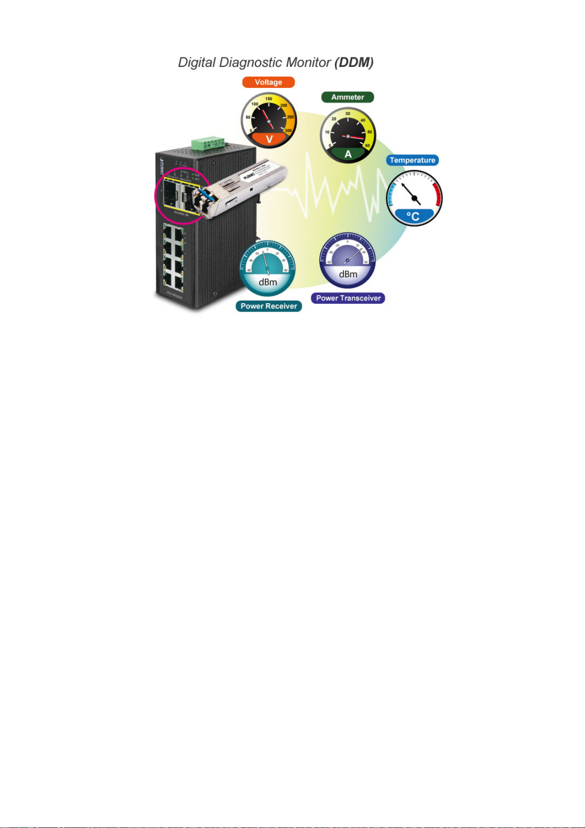
User’s Manual of NS3550-8T-2S
Flexibility and Extension Solution
The two mini-GBIC slots built in the NS3550-8T-2S support Dual-Speed, 100Base-FX and 1000Base-SX/LX SFP (Small
Form-factor Pluggable) fiber-optic modules, meaning the administrator now can flexibly choose the suitable SFP transceiver
according to the transmission distance or the transmission speed required.
1.3 How to Use This Manual
This User Manual is structured as follows:
Section 2 INSTALLATION
The section explains the functions of the Industrial Managed Switch and how to physically install the Industrial
Managed Switch.
Section 3 SWITCH MANAGEMENT
The section contains the information about the software function of the Industrial Managed Switch.
Section 4 WEB CONFIGURATION
The section explains how to manage the Industrial Managed Switch by Web interface.
Section 5 COMMAND LINE INTERFACE
The section describes how to use the Command Line interface (CLI).
Section 6 CLI MODE
The section explains how to manage the Industrial Managed Switch by Command Line interface.
Section 7 SWITCH OPERATION
The chapter explains how to do the switch operation of the Industrial Managed Switch.
Section 8 TROUBLESHOOTING
The chapter explains how to troubleshoot the Industrial Managed Switch.
Appendix A
The section contains cable information of the Industrial Managed Switch.
Appendix B
The section contains Glossary information of the Industrial Managed Switch.
17
Page 18

User’s Manual of NS3550-8T-2S
1.4 Product Features
Physical Port
8-Port 10/100/1000Base-T RJ-45 copper
2 100/1000Base-X mini-GBIC/SFP slots, SFP type auto detection
Industrial Case / Installation
IP30 Aluminum case protection
DIN-Rail and Wall Mount Design
Redundant Power Design
- 12 to 48V DC, redundant power with polarity reverse protect function
- AC 24V power adapter acceptable
Supports EFT protection 6000 VDC for power line
Supports 6000 VDC Ethernet ESD protection
-40 to 75 degrees C operating temperature
Layer 2 Features
Prevents packet loss with back pressure (Half-Duplex) and IEEE 802.3x PAUSE frame flow control (Full-Duplex)
High performance of Store-and-Forward architecture and runt/CRC filtering eliminates erroneous packets to optimize
the network bandwidth
Storm Control support:
Multicast / Unknown-Unicast
Supports VLAN
IEEE 802.1Q Tagged VLAN
Up to 255 VLANs groups, out of 4095 VLAN IDs
Provider Bridging (VLAN Q-in-Q) support (IEEE 802.1ad)
Private VLAN Edge (PVE)
Protocol-based VLAN
MAC-based VLAN
Voice VLAN
Supports Spanning Tree Protocol
STP, IEEE 802.1D Spanning Tree Protocol
RSTP, IEEE 802.1w Rapid Spanning Tree Protocol
MSTP, IEEE 802.1s Multiple Spanning Tree Protocol, spanning tree by VLAN
BPDU Guard
Supports Link Aggregation
802.3ad Link Aggregation Control Protocol (LACP)
Cisco ether-channel (Static Trunk)
Maximum 5 trunk groups, up to 10 ports per trunk group
Up to 20Gbps bandwidth(Duplex Mode)
Provides Port Mirror (many-to-1)
Port Mirroring to monitor the incoming or outgoing traffic on a particular port
Supports E.R.P.S. (Ethernet Ring Protection Switching)
Quality of Service
Ingress Shaper and Egress Rate Limit per port bandwidth control
8 priority queues on all switch ports
18
Page 19

Traffic classification:
- IEEE 802.1p CoS
- IP TOS / DSCP / IP Precedence
- IP TCP/UDP port number
- Typical network application
Strict priority and Weighted Round Robin (WRR) CoS policies
Supports QoS and In/Out bandwidth control on each port
Traffic-policing policies on the switch port
DSCP remarking
Multicast
Supports IGMP Snooping v1, v2 and v3
Supports MLD Snooping v1 and v2
Querier mode support
IGMP Snooping port filtering
MLD Snooping port filtering
MVR (Multicast VLAN Registration)
User’s Manual of NS3550-8T-2S
Security
IEEE 802.1x Port-Based / MAC-Based network access authentication
Build-in RADIUS client to co-operate with the RADIUS servers
TACACS+ login users access authentication
RADIUS / TACACS+ users access authentication
IP-Based Access Control List (ACL)
MAC-Based Access Control List
Source MAC / IP address binding
DHCP Snooping to filter untrusted DHCP messages
Dynamic ARP Inspection discards ARP packets with invalid MAC address to IP address binding
IP Source Guard prevents IP spoofing attacks
Auto DoS rule to defend DoS attack
IP address access management to prevent unauthorized intruder
Management
Switch Management Interfaces
- Web switch management
- Remote Telnet management
- SNMP v1, v2c, and v3 switch management
- SSH / SSL secure access
Four RMON groups (history, statistics, alarms, and events)
IPv6 IP Address / NTP / DNS management
Built-in Trivial File Transfer Protocol (TFTP) client
BOOTP and DHCP for IP address assignment
Firmware upload/download via HTTP / TFTP
DHCP Relay
DHCP Option82
User Privilege levels control
19
Page 20

User’s Manual of NS3550-8T-2S
NTP (Network Time Protocol)
Link Layer Discovery Protocol (LLDP) Protocol
Cable Diagnostic technology provides the mechanism to detect and report potential cabling issues
Reset button for system reboot or reset to factory default
20
Page 21
User’s Manual of NS3550-8T-2S
1.5 Product Specifications
Model Name NS3550-8T-2S
Hardware Specification
Copper Ports 8 10/ 100/1000Base-T RJ-45 Auto-MDI/MDI-X ports
SFP/mini-GBIC Slots
Switch Architecture Store-and-Forward
Switch Fabric 20Gbps / non-blocking
Throughput (packet per second) 14.8Mpps
Address Table 8K entries, automatic source address learning and ageing
Share data Buffer 512 kilobytes
Flow Control IEEE 802.3x Pause Frame for Full-Duplex. Back pressure for Half-Duplex
Jumbo Frame 9Kbytes
Reset Button
ESD Protection 6KV DC
EFT Protection 6KV DC
Enclosure IP30 Aluminum Metal Case
Installation DIN Rail Kit and Wall Mount Kit
Alarm
LED Indicator
Dimensions (W x D x H) 87.8 x 135 x 56mm
Weight 720g
Power Requirements DC 12 to 48V. AC 24V Power Adapter
Power Consumption 10 Watts / 34BTU (Full loading)
Layer 2 function
Basic Management Interfaces Web Browser, Remote Telnet, SNMPv1, v2c
Secure Management Interface SSH, SSL, SNMP v3
Port configuration
Port Status
Port Mirroring
VLAN
Link Aggregation
QoS
2 1000Base-SX/LX/BX SFP interfaces (Port-9 and Port-10)
Compatible with 100Base-FX SFP
< 5 sec: System reboot
> 10 sec: Factory Default
One relay output for power failure. Alarm Relay current carry ability: 1A @ DC
24V
System:
Power 1 (Green)
Power 2 (Green)
Fault Alarm (Green)
Ring (Green)
R.O. (Green)
Port disable/enable
Auto-negotiation 10/100/1000Mbps full and half duplex mode selection
Flow Control disable / enable
Power saving mode control
Display each port’s speed duplex mode, link status, Flow control status. Auto
negotiation status, trunk status.
TX / RX / Both
Many to 1 monitor
802.1Q Tagged Based VLAN ,up to 255 VLAN groups
Q-in-Q tunneling
Private VLAN Edge (PVE)
MAC-based VLAN
Protocol-based VLAN
Voice VLAN
MVR (Multicast VLAN Registration)
Up to 255 VLAN groups, out of 4095 VLAN IDs
IEEE 802.3ad LACP / Static Trunk
Support 5 groups of 10-Port trunk support
Traffic classification based, Strict priority and WRR
8-level priority for switching
- Port Number
- 802.1p priority
Per 10/100/1000T RJ-45 Ports:
LNK/ACT (Green)
1000 (Orange)
Per SFP Interface:
LNK/ACT (Green)
1000 (Orange)
21
Page 22

- 802.1Q VLAN tag
- DSCP/TOS field in IP Packet
IGMP Snooping
MLD Snooping
Access Control List
Bandwidth Control
SNMP MIBs
Standards Conformance
Regulation Compliance FCC Part 15 Class A, CE
Stability Testing
Standards Compliance
Environment
Operating
Storage
IGMP (v1/v2/V3) Snooping, up to 255 multicast Groups
IGMP Querier mode support
MLD (v1/v2) Snooping, up to 255 multicast Groups
MLD Querier mode support
IP-Based ACL / MAC-Based ACL
Up to 123 entries
Per port bandwidth control
Ingress: 500Kb~80Mbps
Egress: 64Kb~80Mbps
RFC-1213 MIB-II
IF-MIB
RFC-1493 Bridge MIB
RFC-1643 Ethernet MIB
RFC-2863 Interface MIB
RFC-2665 Ether-Like MIB
RFC-2819 RMON MIB (Group 1, 2, 3 and 9)
RFC-2737 Entity MIB
RFC-2618 RADIUS Client MIB
RFC-2933 IGMP-STD-MIB
RFC3411 SNMP-Frameworks-MIB
IEEE 802.1X PAE
LLDP
MAU-MIB
IEC60068-2-32 (Free fall)
IEC60068-2-27 (Shock)
IEC60068-2-6 (Vibration)
IEEE 802.3 10Base-T
IEEE 802.3u 100Base-TX / 100Base-FX
IEEE 802.3z Gigabit SX/LX
IEEE 802.3ab Gigabit 1000T
IEEE 802.3x Flow Control and Back pressure
IEEE 802.3ad Port trunk with LACP
IEEE 802.1D Spanning Tree Protocol
IEEE 802.1w Rapid Spanning Tree Protocol
IEEE 802.1s Multiple Spanning Tree Protocol
IEEE 802.1p Class of service
IEEE 802.1Q VLAN Tagging
IEEE 802.1x Port Authentication Network Control
IEEE 802.1ab LLDP
RFC 768 UDP
RFC 793 TFTP
RFC 791 IP
RFC 792 ICMP
RFC 2068 HTTP
RFC 1112 IGMP version 1
RFC 2236 IGMP version 2
RFC 3376 IGMP version 3
RFC 2710 MLD version 1
FRC 3810 MLD version 2
Temperature: -40 ~ 75 degrees C
Relative Humidity: 5 ~ 95% (Non-condensing)
Temperature: -40 ~ 75 degrees C
Relative Humidity: 5 ~ 95% (Non-condensing)
User’s Manual of NS3550-8T-2S
22
Page 23
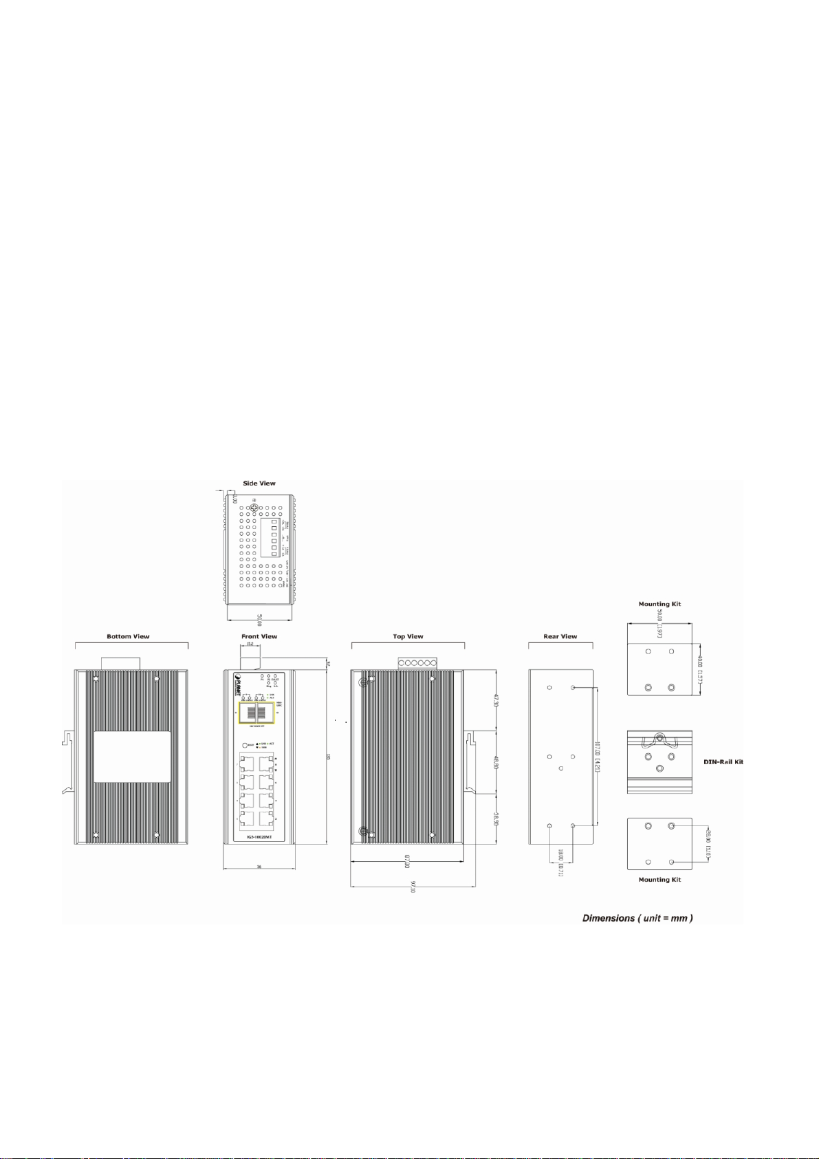
2. INSTALLATION
2.1 Hardware Description
The Industrial Managed Switch provides three different running speeds – 10Mbps, 100Mbps and 1000Mbps in the same Switch
and automatically distinguishes the speed of incoming connection.
This section describes the hardware features of Industrial Managed Switch. For easier management and control of the Industrial
Managed Switch, familiarize yourself with its display indicators, and ports. Front panel illustrations in this chapter display the unit
LED indicators. Before connecting any network device to the Industrial Managed Switch, read this chapter carefully.
2.1.1 Physical Dimensions
Dimensions (W x D x H) : 87.8 x 135 x 56mm
23
Page 24
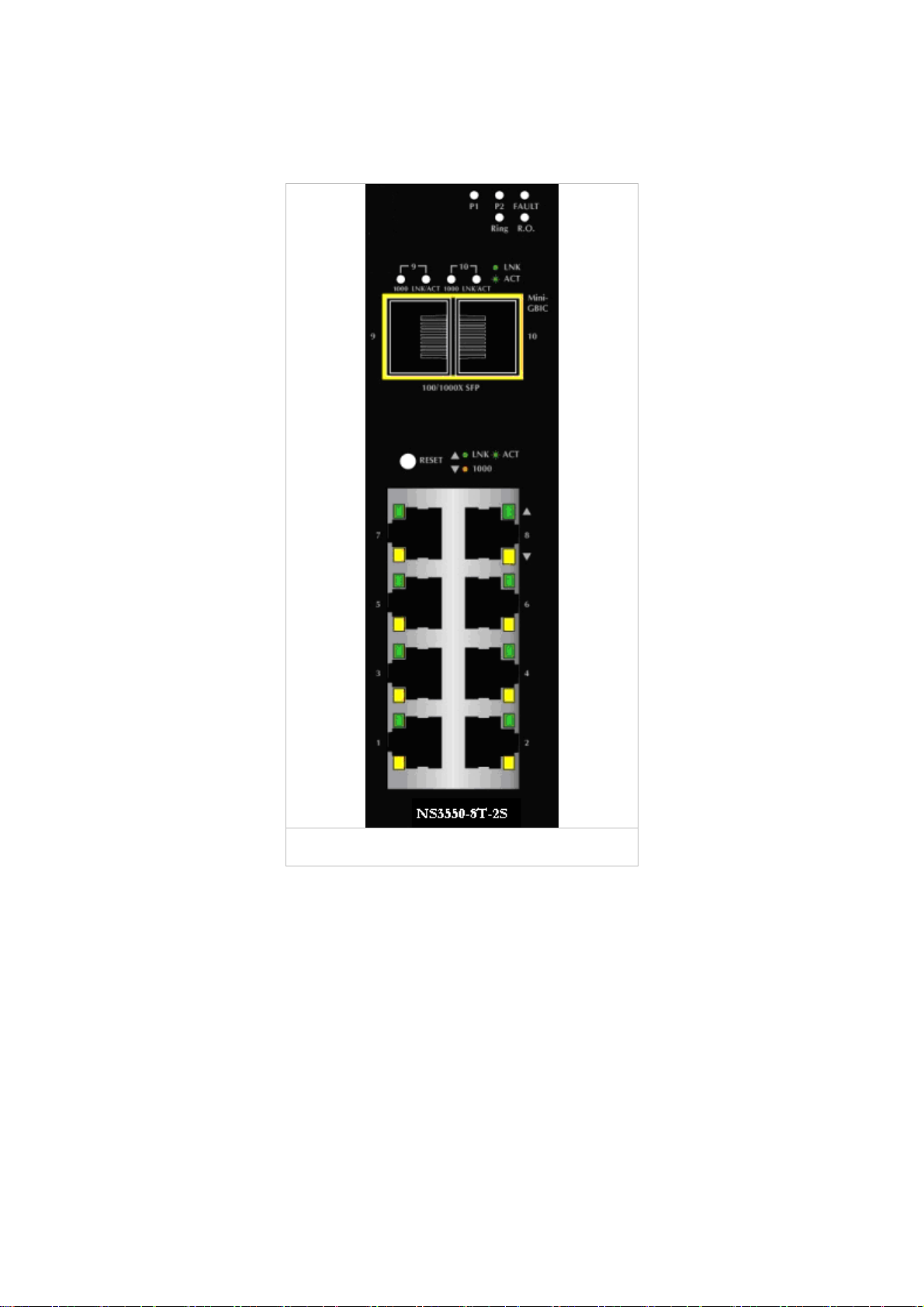
2.1.2 Front Panel
Figure 2-1 shows the front panel of Industrial Managed Switch.
Figure 2-1: NS3550-8T-2S Switch Front Panel
24
Page 25
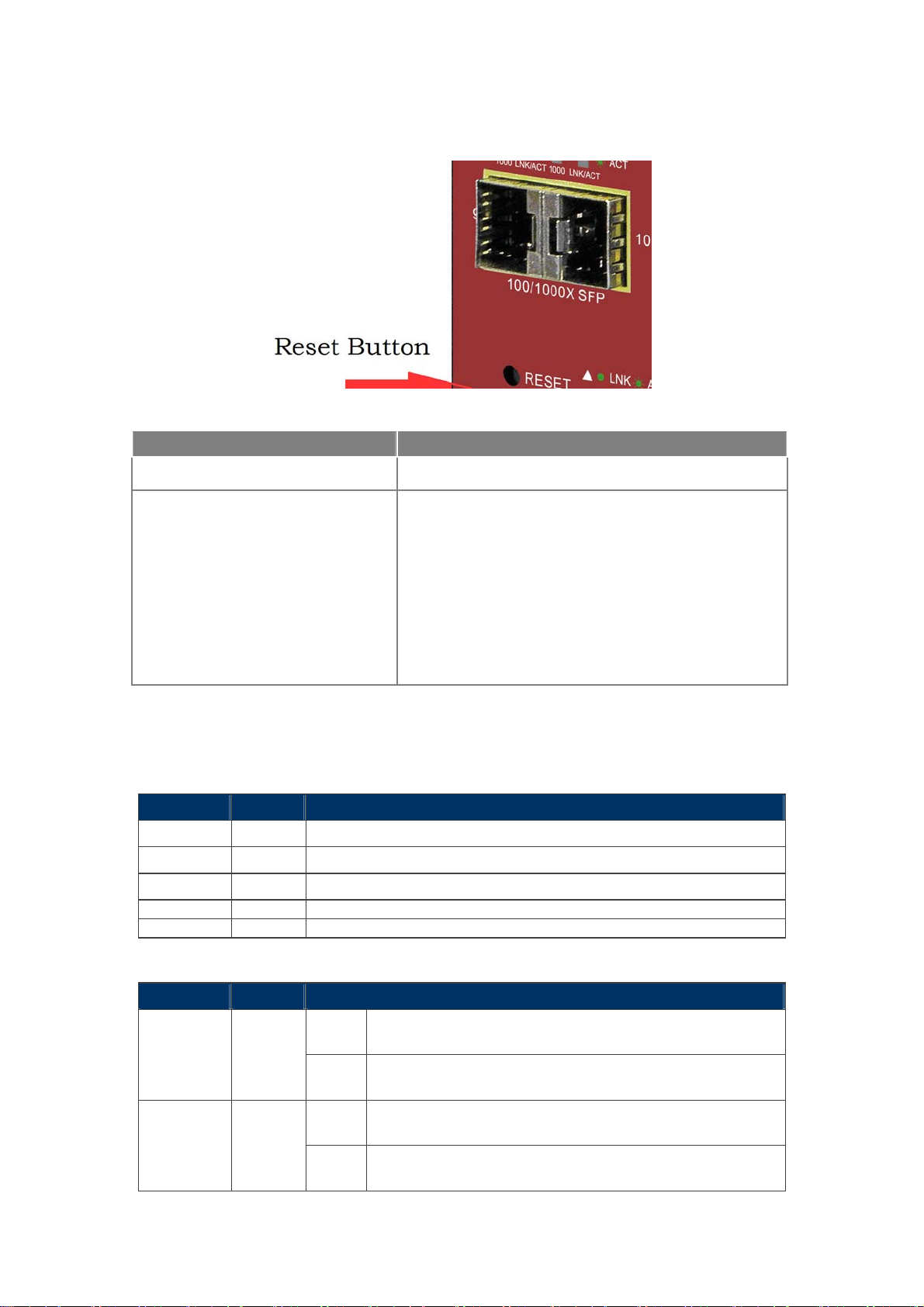
■ Reset Button
On the left of the front panel, the reset button is designed for rebooting the Industrial Managed Switch without turning off
and on the power. It also can reset the Industrial Managed Switch to factory default mode.
Figure 2-2: Reset Button of Industrial Managed Switch
Reset Button Pressed and Released Function
< 5 sec: System Reboot Reboot the Industrial Managed Switch
Reset the Industrial Managed Switch to Factory Default
configuration. The Industrial Managed Switch will then reboot
and load the default settings as below:
> 10 sec: Factory Default
Default Username: admin
Default Password: admin
Default IP address: 192.168.0.100
Subnet mask: 255.255.255.0
Default Gateway: 192.168.0.254
2.1.3 LED Indicators
System
LED Color Function
P1 Green
P2 Green
Fault Green
Ring Green
R.O.* Green
Per 10/100/1000Base-T Port
LED Color Function
LNK / ACT Green
1000 Orange
Indicates power 1 has power.
Indicates power 2 has power.
Indicates either power 1 or power 2 has no power.
Lights to indicate that the ERPS Ring has been created successfully.
Lights to indicate that Switch has enabled Ring Owner.
Light
Blink
Light
Off
Indicates the link through that port is successfully
established.
Indicates that the Switch is actively sending or receiving
data over that port.
Indicates that the port is successfully connecting to the
network at 1000Mbps.
Indicates that the port is successfully connecting to the
network at 10Mbps or 100Mbps.
25
Page 26

Per SFP Interface
LED Color Function
User’s Manual of NS3550-8T-2S
Light
Indicates the link through that port is successfully
established.
LNK / ACT Green
Blink
Light
Indicates that the Switch is actively sending or receiving data
over that port.
Indicates that the port is successfully connecting to the
network at 1000Mbps.
1000 Orange
Off
Indicates that the port is successfully connecting to the
network at 100Mbps.
2.1.4 Switch Upper Panel
The Upper Panel of the Industrial Managed Switch indicates a DC inlet power socket and consists of one terminal block
connector within 6-contacts. It accepts input power from 12 to 48V DC, and also AC 24V.
Figure 2-3: NS3550-8T-2S Upper Panel
26
Page 27

User’s Manual of NS3550-8T-2S
2.2 Installing Industrial Managed Switch
This section describes how to install your Industrial Managed Switch and make connections to the Industrial Managed
Switch. Please read the following topics and perform the procedures in the order being presented. To install your Industrial
Managed Switch on a desktop or shelf, simply complete the following steps.
In this paragraph, we will describe how to install the Industrial Managed Switch and the installation points attended to it.
2.2.1 Installation Steps
1. Unpack the Industrial Managed Switch
2. Check if the DIN-Rail is screwed on the Industrial Managed Switch or not. If the DIN-Rail is not screwed on the
Industrial Managed Switch, please refer to DIN-Rail Mounting section for DIN-Rail installation. If users want to
wall-mount the Industrial Managed Switch, please refer to the Wall Mount Plate Mounting section for wall mount plate
installation.
3. To hang the Industrial Managed Switch on the DIN-Rail track or wall.
4. Power on the Industrial Managed Switch. Please refer to the Wiring the Power Inputs section for knowing the
information about how to wire the power. The power LED on the Industrial Managed Switch will light up. Please refer to
the LED Indicators section for indication of LED lights.
5. Prepare the twisted-pair, straight through Category 5 cable for Ethernet connection.
6. Insert one side of RJ-45 cable (category 5) into the Industrial Managed Switch Ethernet port (RJ-45 port) and the
other side of RJ-45 cable (category 5) to the network device’s Ethernet port (RJ-45 port), e.g. Switch PC or Server. The
UTP port (RJ-45) LED on the Industrial Managed Switch will light up when the cable is connected with the network
device. Please refer to the LED Indicators section for LED light indication.
Make sure that the connected network devices support MDI/MDI-X. If it does not support,
use the crossover category-5 cable.
7. When all connections are set and LED lights all show normally, the installation is completed.
27
Page 28

2.2.2 DIN-Rail Mounting
This section describes how to install the Industrial Managed Switch.
There are two methods to install the Industrial Managed Switch. DIN-Rail Mounting and Wall Mount Plate Mounting. Please
read the following topics and perform the procedures in the order being presented.
Step 1: Screw the DIN-Rail on the Industrial Managed Switch.
Step 2: Lightly press the bottom of DIN-Rail into the track.
28
Page 29

Step 3: Check the DIN-Rail is tightly on the track.
User’s Manual of NS3550-8T-2S
Please refer to following procedures to remove the Industrial Managed Switch from the track.
Step 4: Lightly press the bottom of DIN-Rail to remove it from the track.
29
Page 30

User’s Manual of NS3550-8T-2S
2.2.3 Wall Mount Plate Mounting
To install the Industrial Managed Switch on the wall. Please follow the instructions below.
Step 1: Remove the DIN-Rail from the Industrial Managed Switch. Use the screwdriver to loosen the screws and remove the
DIN-Rail.
Step 2: Place the wall mount plate on the rear panel of the Industrial Managed Switch.
Step 3: Use the screwdriver to screw the wall mount plate on the Industrial Managed Switch.
Step 4: Use the hook holes at the corners of the wall mount plate to hang the Industrial Managed Switch on the wall.
Step 5: To remove the wall mount plate, reverse the steps above.
30
Page 31

2.3 Wiring the Power Inputs
The 6-contacts terminal block connector on the top panel of Industrial Managed Switch is used for two DC redundant power
inputs. Please follow the steps to insert the power wire. The PWR1 is 1(-) & 2(+) and PWR2 is 5(-) & 6(+) contact.
Remember: Tighten the wire-clamp screws for preventing the wires from loosening..
1 2 3 4 5 6
Power 1 Fault Power 2
- + - +
Figure 2-4: 6-Contacts of Terminal Block Connector
1. The wire gauge for the terminal block should be in the range of 12 ~ 24 AWG.
2. Follow any of the procedures like inserting the wires or tighten the wire-clamp screws.
Ensure the power is OFF to prevent from getting an electric shock.
2.4 Wiring the Fault Alarm Contact
The fault alarm contacts are in the middle (3 & 4) of the terminal block connector as the picture shows below. Inserting the wires,
the Industrial Managed Switch will detect the fault status of the power failure, or port link failure (available for managed model).
The following illustration shows an application example for wiring the fault alarm contacts
Insert the wires into the fault alarm contacts
1. The wire gauge for the terminal block should be in the range of 12 ~ 24 AWG.
2. Follow any of the procedures like inserting the wires or tighten the wire-clamp screws.
Ensure the power is OFF to prevent to get an electric shock.
2.5 Cabling
10/100/1000Base-T and 100Base-FX / 1000Base-SX/LX
31
Page 32

User’s Manual of NS3550-8T-2S
All 10/100/1000Base-T ports come with Auto-Negotiation capability. They automatically support 1000Base-T, 100Base-TX
and 10Base-T networks. Users only need to plug a working network device into one of the 10/100/1000Base-T ports, and
then turn on the Industrial Managed Switch. The port will automatically runs in 10Mbps, 20Mbps, 100Mbps or 200Mbps
and 1000Mbps or 2000Mbps after the negotiation with the connected device.
The Industrial Managed Switch has two SFP interfaces that support 100/1000 dual speed mode (Optional Multi-mode /
Single-mode 100Base-FX / 1000Base-SX/LX SFP module)
Cabling
Each 10/100/1000Base-T port uses RJ-45 sockets -- similar to phone jacks -- for connection of unshielded twisted-pair
cable (UTP). The IEEE 802.3 / 802.3u 802.3ab Fast / Gigabit Ethernet standard requires Category 5 UTP for 100Mbps
100Base-TX. 10Base-T networks can use Cat.3, 4, 5 or 1000Base-T use 5/5e/6 UTP (see table below). Maximum distance
is 100meters (328 feet). The 100Base-FX / 1000Base-SX/LX SFP slot is used as LC connector with optional SFP module.
Please see table below and know more about the cable specifications.
Port Type Cable Type Connector
10Base-T Cat 3, 4, 5, 2-pair RJ-45
100Base-TX Cat.5 UTP, 2-pair RJ-45
1000Base-T Cat.5/5e/6 UTP, 2-pair RJ-45
100Base-FX
1000Base-SX/LX
50 / 125µm or 62.5 / 125µm multi-mode 9 / 125µm single-mode
50 / 125µm or 62.5 / 125µm multi-mode 9 / 125µm single-mode
LC (Multi / Single mode)
LC (Multi / Single mode)
Any Ethernet devices like hubs/ PCs can connect to the Industrial Managed Switch by using straight-through wires. The
eight-10/100/1000Mbps ports are auto-MDI/MDI-X and can be used on straight-through or crossover cable.
32
Page 33

2.5.1 Installing the SFP Transceiver
The sections describe how to insert an SFP transceiver into an SFP slot.
The SFP transceivers are hot-pluggable and hot-swappable. You can plug-in and out the transceiver to/from any SFP port
without having to power down the Industrial Managed Switch as the Figure 2-5 shows.
Figure 2-5: Plug-in the SFP Transceiver
Approved IFS SFP Transceivers
IFS Industrial Managed Switch supports 100/1000 dual mode with both Single mode and Multi-mode SFP transceiver.
The following list of approved IFS SFP transceivers is correct at the time of publication:
Gigabit SFP Transceiver Modules
S30-1SLC/A-10 SFP, LC Connector, Single Mode, Gigabit, 1 fiber, 1310nm/1550nm, 10km , A End
S30-1SLC/A-20 SFP, LC Connector, Single Mode, Gigabit, 1 fiber, 1310nm/1550nm, 20km, A End
S30-1SLC/A-60 SFP, LC Connector, Single Mode, Gigabit, 1 fiber, 1310nm/1550nm, 60km, A End
S30-1SLC/B-10 SFP, LC Connector, Single Mode, Gigabit, 1 fiber, 1550nm/1310nm, 10km , B End
S30-1SLC/B-20 SFP, LC Connector, Single Mode, Gigabit, 1 fiber, 1550nm/1310nm, 20km, B End
S30-1SLC/B-60 SFP, LC Connector, Single Mode, Gigabit, 1 fiber, 1550nm/1310nm, 60km, B End
S30-2MLC SFP, LC Connector, Multi-Mode, Gigabit, 2 fiber,850nm/850nm, 550m
S30-2MLC-2 SFP, LC Connector, Multi-Mode, Gigabit, 2 fiber,1310nm/1310nm, 2km
S30-2SLC-10 SFP, LC Connector, Single Mode, Gigabit, 2 fiber,1310nm/1310nm, 10km
S30-2SLC-30 SFP, LC Connector, Single Mode, Gigabit, 2 fiber,1310nm/1310nm, 30km
S30-2SLC-70 SFP, LC Connector, Single Mode, Gigabit, 2 fiber,1550nm/1550nm, 70km
S30-RJ SFP, RJ-45, Gigabit, 100m
S35-2MLC SFP, LC Connector, Multi-Mode, Gigabit, 2 fiber,850nm/850nm, 550m, Hardened
-40~75°C
S35-2SLC-10 SFP, LC Connector, Single Mode, Gigabit, 2 fiber,1310nm/1310nm, 10km,
Hardened -40~75°C
SFP, LC Connector, Single Mode, Gigabit, 2 fiber,1310nm/1310nm, 30km,
S35-2SLC-30
Hardened -40~75°C
SFP, LC Connector, Single Mode, Gigabit, 2 fiber,1550nm/1550nm, 70km,
S35-2SLC-70
Hardened -40~75°C
Fast Ethernet SFP Transceiver Modules
SFP, LC Connector, Single Mode, 10/100 Fast Ethernet, 1 fiber, 1310nm/1550nm,
S20-1SLC/A-20
20km , A End
SFP, LC Connector, Single Mode, 10/100 Fast Ethernet, 1 fiber, 1310nm/1550nm,
S20-1SLC/B-20
20km , B End
S20-2MLC-2 SFP, LC Connector, Multi Mode, 10/100 Fast Ethernet, 2 fiber,1310nm/1310nm, 2km
SFP, LC Connector, Single Mode, 10/100 Fast Ethernet, 2 fiber,1310nm/1310nm,
S20-2SLC-20
20km
33
Page 34

User’s Manual of NS3550-8T-2S
SFP, LC Connector, Multi Mode, 10/100 Fast Ethernet, 2 fiber,1310nm/1310nm, 2km,
S25-2MLC-2
Hardened -40~75°C
SFP, LC Connector, Single Mode, 10/100 Fast Ethernet, 2 fiber,1310nm/1310nm,
S25-2SLC-20
20km, Hardened -40~75°C
It is recommended to use IFS SFPs on the Industrial Managed Switch. If you insert an SFP
transceiver that is not supported, the Industrial Managed Switch will not recognize it.
1000Base-SX/LX:
Before connecting the other switches, workstation or media converter,
1. Make sure both sides of the SFP transceiver are with the same media type; for example, 1000Base-SX to 1000Base-SX,
1000Bas-LX to 1000Base-LX.
2. Check the fiber-optic cable type that matches the SFP transceiver model.
To connect to 1000Base-SX SFP transceiver, use the Multi-mode fiber cable with one side being male duplex LC
To connect to 1000Base-LX SFP transceiver, use the Single-mode fiber cable with one side being male duplex LC
Connecting the fiber cable
1. Attach the duplex LC connector to the network cable and put into the SFP transceiver.
2. Connect the other end of the cable to a device – switches with SFP installed, fiber NIC to a workstation or a media
converter.
3. Check the LNK/ACT LED of the SFP slot on the front of the Industrial Managed Switch. Make sure that the SFP
transceiver is operating correctly.
connector type.
connector type.
100Base-FX:
Before connecting the other switches, workstation or media converter,
1. Make sure both sides of the SFP transceiver are with the same media type or WDM pair, for example: 100Base-FX to
100Base-FX, 100Base-BX20-U to 100Base-BX20-D.
2. Check the fiber-optic cable type that matches the SFP transceiver model.
To connect to 1000Base-SX SFP transceiver, use the Multi-mode fiber cable with one side being male duplex LC
connector type.
To connect to 1000Base-LX SFP transceiver, use the Single-mode fiber cable with one side being male duplex LC
connector type.
Connecting the fiber cable
1 Attach the duplex LC connector to the network cable and put into the SFP transceiver.
2 Connect the other end of the cable to a device – switches with SFP installed, fiber NIC to a workstation or a media
converter.
3. Check the LNK/ACT LED of the SFP slot on the front of the Industrial Managed Switch. Make sure that the SFP
transceiver is operating correctly.
4. Check the Link mode of the SFP port if the link failed. Co works with some fiber-NICs or Media Converters, set the Link
mode to “100 Force” is needed.
2.5.2 Removing the Module
1. Make sure there is no network activity by consulting or checking with the network administrator. Or through the
management interface of the switch/converter (if available) to disable the port in advance.
2. Remove the Fiber Optic Cable gently.
3. Turn the handle of the MGB / MFB module to horizontal.
4. Pull out the module gently through the lever..
34
Page 35

User’s Manual of NS3550-8T-2S
Figure 2-6: Pull Out the SFP Transceiver Module
Never pull out the module without pulling the lever or the push bolts on the module. Directly pulling
out the module with forcecould damage the module and SFP module slot of the device.
35
Page 36

3. SWITCH MANAGEMENT
This chapter explains the methods that you can use to configure management access to the Industrial Managed Switch. It
describes the types of management applications and the communication and management protocols that deliver data between
your management device (workstation or personal computer) and the system. It also contains information about port connection
options.
This chapter covers the following topics:
Requirements
Management Access Overview
Remote Telnet Access
Web Management Access
SNMP Access
Standards, Protocols, and Related Reading
3.1 Requirements
Workstations running Windows XP/2003, Vista, Windows 7, MAC OS X, Linux, Fedora, Ubuntu or other platforms
compatible with TCP/IP protocols.
Workstation is installed with Ethernet NIC (Network Interface Card)
Ethernet Port connection
Network cables - Use standard network (UTP) cables with RJ45 connectors.
The above workstation is installed with WEB Browser and JAVA runtime environment Plug-in
It is recommended to use Internet Explore 7.0 or above to access Industrial Managed Switch.
36
Page 37

User’s Manual of NS3550-8T-2S
3.2 Management Access Overview
The Industrial Managed Switch gives you the flexibility to access and manage it using any or all of the following methods:
Remote Telnet Interface
Web browser Interface
An external SNMP-based network management application
The Remote Telnet and Web browser interface support is embedded in the Industrial Managed Switch software and is
available for immediate use. Each of these management methods has their own advantages. Table 3-1 compares the three
management methods.
Method Advantages Disadvantages
Remote
Telnet
Web Browser
SNMP Agent
Text-based
Telnet functionality built into Windows
XP/2003, Vista, Windows 7 operating
systems
Can be accessed from any location
Ideal for configuring the switch remotely
Compatible with all popular browsers
Can be accessed from any location
Most visually appealing
Communicates with switch functions at
the MIB level
Based on open standards
Table 3-1: Management Methods Comparison
Security can be compromised (hackers need
only know the IP address)
Security can be compromised (hackers need
only know the IP address and subnet mask)
May encounter lag times on poor connections
Requires SNMP manager software
Least visually appealing of all three methods
Some settings require calculations
Security can be compromised (hackers need
only know the community name)
37
Page 38

3.3 Remote Telnet
The Remote Telnet is an IP-based command line user interface for performing system administration such as displaying
statistics or changing option settings. Using this method, you can access the Industrial Managed Switch remote telnet
interface from personal computer, or workstation in the same Ethernet environment as long as you know the current IP address
of the Industrial Managed Switch.
Figure 3-1: Remote Telnet Interface Management
In Windows system, you may click “Start” and then choose “Acessories”and “Command Prompt”. Please input “telnet
192.168.0.100” and press “enter’ from your keyboard. You will see the following screen appear:
Figure 3-2: Remote Telnet Interface Main Screen of Industrial Managed Switch
For more information about using the Remote Telnet interface, refer to Chapter 5 Remote Telnet Interface Management.
38
Page 39

3.4 Web Management
The Industrial Managed Switch offers management features that allow users to manage the Industrial Managed Switch from
anywhere on the network through a standard browser such as Microsoft Internet Explorer. After you set up your IP address for
the Industrial Managed Switch, you can access the Industrial Managed Switch’s Web interface applications directly in your
Web browser by entering the IP address of the Industrial Managed Switch.
Figure 3-3: Web Management
You can then use your Web browser to list and manage the Industrial Managed Switch configuration parameters from one
central location; the Web Management requires either Microsoft Internet Explorer 7.0 or later, Safari or Mozilla Firefox 1.5 or
later.
Figure 3-4: Web Main Screen of Industrial Managed Switch
39
Page 40

3.5 SNMP-Based Network Management
You can use an external SNMP-based application to configure and manage the Industrial Managed Switch, such as SNMP
Network Manager, HP Openview Network Node Management (NNM) or What’s Up Gold. This management method requires
the SNMP agent on the Industrial Managed Switch and the SNMP Network Management Station to use the same community
string. This management method, in fact, uses two community strings: the get community string and the set community
string. If the SNMP Net-work management Station only knows the set community string, it can read and write to the MIBs.
However, if it only knows the get community string, it can only read MIBs. The default gets and sets community strings for the
Industrial Managed Switch are public.
Figure 3-5: SNMP Management
40
Page 41

4. WEB CONFIGURATION
This section introduces the configuration and functions of the Web-based management.
About Web-based Management
The Industrial Managed Switch offers management features that allow users to manage the Industrial Managed Switch from
anywhere on the network through a standard browser such as Microsoft Internet Explorer.
The Web-based Management supports Internet Explorer 7.0. It is based on Java Applets with an aim to reduce network
bandwidth consumption, enhance access speed and present an easy viewing screen.
By default, IE7.0 or later version does not allow Java Applets to open sockets. The user has to
explicitly modify the browser setting to enable Java Applets to use network ports.
The Industrial Managed Switch can be configured through an Ethernet connection, making sure the manager PC must be set on
the same the IP subnet address as the Industrial Managed Switch.
For example, the default IP address of the Industrial Managed Switch is 192.168.0.100, then the manager PC should be set at
192.168.0.x (where x is a number between 1 and 254, except 100), and the default subnet mask is 255.255.255.0.
If you have changed the default IP address of the Industrial Managed Switch to 192.168.1.1 with subnet mask 255.255.255.0
via console, then the manager PC should be set at 192.168.1.x (where x is a number between 2 and 254) to do the relative
configuration on manager PC.
Figure 4-1-1: Web Management
41
Page 42

Logging on the Industrial Managed Switch
1. Use Internet Explorer 7.0 or above Web browser and enter the factory-default IP address to access the Web interface.
The factory-default IP Address is as follows:
http://192.168.0.100
2. When the following login screen appears, please enter the default username "admin" with password “admin” (or the
username/password you have changed via console) to login the main screen of Industrial Managed Switch. The login
screen in Figure 4-1-2 appears.
Figure 4-1-2: Login Screen
Default User name: admin
Default Password: admin
After entering the username and password, the main screen appears as Figure 4-1-3.
Figure 4-1-3: Default Main Page
Now, you can use the Web management interface to continue the switch management or manage the Industrial Managed
Switch by Web interface. The Switch Menu on the left of the web page let you access all the commands and statistics the
Managed Switch provides.
42
Page 43

User’s Manual of NS3550-8T-2S
1. It is recommended to use Internet Explore 7.0 or above to access Industrial Managed
Switch.
2. The changed IP address take effect immediately after clicking on the Save button. You need
to use the new IP address to access the Web interface.
3. For security reason, please change and memorize the new password after this first setup.
4. Only accept command in lowercase letter under web interface.
43
Page 44

User’s Manual of NS3550-8T-2S
4.1 Main Web Page
The Industrial Managed Switch provides a Web-based browser interface for configuring and managing it. This interface allows
you to access the Industrial Managed Switch using the Web browser of your choice. This chapter describes how to use the
Industrial Managed Switch’s Web browser interface to configure and manage it.
Main Functions Menu SFP Port Link Status
Copper Port Link Status
Figure 4-1-4: Main Page
Panel Display
The web agent displays an image of the Industrial Managed Switch’s ports. The Mode can be set to display different information
for the ports, including Link up or Link down. Clicking on the image of a port opens the Port Statistics page.
The port status is illustrated as follows:
Help Button Main Screen
State Disabled Down Link
RJ-45 Ports
SFP Ports
Main Screen
44
Page 45

Main Menu
Using the onboard web agent, you can define system parameters, manage and control the Industrial Managed Switch, and all
its ports, or monitor network conditions. Via the Web-Management, the administrator can set up the Industrial Managed Switch
by selecting the functions those listed in the Main Function. The screen in Figure 4-1-5 appears.
Figure 4-1-5: Industrial Managed Switch Main Functions Menu
45
Page 46

User’s Manual of NS3550-8T-2S
4.2 System
Use the System menu items to display and configure basic administrative details of the Industrial Managed Switch. Underr the
System, the following topics are provided to configure and view the system information: This section has the following items:
■ System Information The switch system information is provided here.
■ IP Configuration Configure the switch-managed IP information on this page.
■ IPv6 Configuration Configure the switch-managed IPv6 information on this page.
■ Users Configuration
■ Privilege Levels
■ NTP Configuration Configure NTP on this page.
■ UPnP Configure UPnP on this page.
■ DHCP Relay Configure DHCP Relay on this page.
■ DHCP Relay Statistics This page provides statistics for DHCP relay.
■ CPU Load This page displays the CPU load, using a SVG graph.
■ System Log The switch system log information is provided here.
This page provides an overview of the current users. Currently the only way
to login as another user on the web server is to close and reopen the
browser.
This page provides an overview of the privilege levels.
■ Detailed Log The switch system detailed log information is provided here.
■ Remote Syslog Configure remote syslog on this page.
■ SMTP Configuration Configure SMTP function on this page.
■ EEE Power Reduction Configuration energy efficient ethernet power reduction on this page
■ Thermal Protection Configure thermal protection on this page.
■ Web Firmware Upgrade This page facilitates an update of the firmware controlling the switch.
■ TFTP Firmware Upgrade Upgrade the firmware via TFTP server
■ Configuration Backup
■ Configuration Upload
■ Image Select
■ Factory Default
■ System Reboot You can restart the switch on this page. After restart, the switch will boot
You can save the switch configuration. The configuration file is in XML format
with a hierarchy of tags.
You can load the switch configuration. The configuration file is in XML format
with a hierarchy of tags.
Configurati
You can reset the configuration of the switch on this page. Only the IP
configuration is retained.
normally.
on active or alternate firmware on this page.
46
Page 47

User’s Manual of NS3550-8T-2S
4.2.1 System Information
The System Info page provides information for the current device information. System Info page helps a switch administrator to
identify the hardware MAC address, software version and system uptime. The screen in Figure 4-2-1 appears.
Figure 4-2-1: System Information Page Screenshot
The page includes the following fields:
Object Description
Contact
Name
Location
MAC Address
Power
Temperature
System Date
System Up time
Software Version
Software Date
Buttons
Auto-refresh : Check this box to refresh the page automatically. Automatic refresh occurs every 3 seconds.
: Click to refresh the page.
The system contact is configured in Configuration | System | Information | System
Contact.
The system name is configured in Configuration | System | Information | System Name.
The system location is configured in Configuration | System | Information | System
Location.
The MAC Address of this Industrial Managed Switch.
The Power 1 and Power 2 ON/OFF Status display.
The Temperature shows the current temperature status of the switch
The current (GMT) system time and date. The system time is obtained through the
configured SNTP Server, if any.
The period of time the device has been operational.
The software version of the Industrial Managed Switch.
The date when the switch software was produced.
4.2.2 IP Configuration
The IP Configuration includes the IP Address, Subnet Mask and Gateway. The Configured column is used to view or change the
IP configuration. Fill out the IP Address, Subnet Mask and Gateway for the device. The screen in Figure 4-2-2 appears.
47
Page 48

User’s Manual of NS3550-8T-2S
Figure 4-2-2: IP Configuration Page Screenshot
The current column is used to show the active IP configuration.
Object Description
DHCP Client
IP Address
IP Mask
IP Router
VLAN ID
DNS Server
DNS Proxy
Buttons
: Click to save changes.
: Click to undo any changes made locally and revert to previously saved values.
Enable the DHCP client by checking this box. If DHCP fails and the configured IP
address is zero, DHCP will retry. If DHCP server does not respond around 35 seconds
and the configured IP address is non-zero, DHCP will stop and the configured IP
settings will be used. The DHCP client will announce the configured System Name as
host name to provide DNS lookup.
Provide the IP address of this switch in dotted decimal notation.
Provide the IP mask of this switch dotted decimal notation.
Provide the IP address of the router in dotted decimal notation.
Provide the managed VLAN ID. The allowed range is 1 through 4095.
Provide the IP address of the DNS Server in dotted decimal notation.
When DNS proxy is enabled, DUT will relay DNS requests to the current configured
DNS server on DUT, and reply as a DNS resolver to the client device on the network.
: Click to renew DHCP Client. This button is only available if DHCP Client is enabled.
4.2.3 IPv6 Configuration
Configure the switch-managed IPv6 information on this page.
The Configured column is used to view or change the IPv6 configuration. The Current column is used to show the active IPv6
configuration. The screen in Figure 4-2-3 appears.
48
Page 49

User’s Manual of NS3550-8T-2S
The page includes the following fields:
Object Description
Auto Configuration
Address
Prefix
Router
Buttons
Figure 4-2-3: IPv6 Configuration Page Screenshot
Enable IPv6 auto-configuration by checking this box. If system cannot obtain the
stateless address in time, the configured IPv6 settings will be used. The router
may delay responding to a router solicitation for a few seconds. The total time
needed to complete auto-configuration can be significantly longer.
Provide the IPv6 address of this switch. IPv6 address is in 128-bit records
represented as eight fields of up to four hexadecimal digits with a colon
separating each field (:).
For example, 'fe80::215:c5ff:fe03:4dc7'. The symbol '::' is a special syntax that
can be used as a shorthand way of representing multiple 16-bit groups of
contiguous zeros; but it can appear only once. It can also represent a legally valid
IPv4 address. For example, '::192.1.2.34'.
Provide the IPv6 Prefix of this switch. The allowed range is 1 to 128.
Provide the IPv6 gateway address of this switch. IPv6 address is in 128-bit
records represented as eight fields of up to four hexadecimal digits with a colon
separating each field (:).
For example, 'fe80::215:c5ff:fe03:4dc7'. The symbol '::' is a special syntax that
can be used as a shorthand way of representing multiple 16-bit groups of
contiguous zeros; but it can appear only once. It can also represent a legally valid
IPv4 address. . For example, '::192.1.2.34'.
: Click to save changes.
: Click to undo any changes made locally and revert to previously saved values.
: Click to renew IPv6 Auto Configuration. This button is only available if IPv6 Auto Configuration is enabled.
4.2.4 Users Configuration
This page provides an overview of the current users. Currently the only way to login as another user on the web server is to
close and reopen the browser. After setup is completed, please press “Save” button to take effect. Please login web interface
with new user name and password, the screen in Figure 4-2-4 appears.
Figure 4-2-4: Users Configuration Page Screenshot
49
Page 50

The page includes the following fields:
Object
User’s Manual of NS3550-8T-2S
Description
User Name
Privilege Level
Buttons
: Click to add a new user.
The name identifies the user.
The privilege level of the user. The allowed range is 1 to 15. If the privilege level
value is 15, it can access all groups, i.e. granted the full control of the device. But
others value need to refer to each group privilege level. User's privilege should
be the same or greater than the group privilege level to have the access to that
group. By default setting, almost group privilege level 5 has the read-only access
and privilege level 10 has the read-write access. And the system maintenance
(software upload, factory defaults, etc.) needs user privilege level 15. Generally,
the privilege level 15 can be used for an administrator account, privilege level 10
for a standard user account and privilege level 5 for a guest account.
Add / Edit User
This page configures a user – add, edit or delete user.
Figure 4-2-5: Add / Edit User Configuration Page Screenshot
The page includes the following fields:
Object
User Name
Password
Privilege Level
Buttons
: Click to save changes.
: Click to undo any changes made locally and revert to previously saved values.
Description
A string identifies the user name whose entry should belong to. The allowed
string length is 1 to 32. The valid user name is a combination of letters, numbers
and underscores.
The password of the user. The allowed string length is 0 to 32.
The privilege level of the user. The allowed range is 1 to 15. If the privilege level
value is 15, it can access all groups, i.e. granted the full control of the device. But
others value need to refer to each group privilege level. User's privilege should
be same or greater than the group privilege level to have the access to that
group. By default setting, most groups privilege level 5 has the read-only access
and privilege level 10 has the read-write access. And the system maintenance
(software upload, factory defaults and etc.) need user privilege level 15.
Generally, the privilege level 15 can be used for an administrator account,
privilege level 10 for a standard user account and privilege level 5 for a guest
account.
: Click to undo any changes made locally and return to the Users.
: Delete the current user. This button is not available for new configurations (Add new user)
50
Page 51

User’s Manual of NS3550-8T-2S
Figure 4-2-6: User Configuration Page Screenshot
After changing the default password, if you forget the password, please press the “Reset” button
on the front panel of the Industrial Managed Switch over 10 seconds and then release. The
current setting includes VLAN, and will be lost and the Industrial Managed Switch will restore to
the default mode.
4.2.5 Privilege Levels
This page provides an overview of the privilege levels. After setup is completed, please press “Save” button to take effect.
Please login web interface with new user name and password, the screen in Figure 4-2-7 appears.
51
Page 52

User’s Manual of NS3550-8T-2S
Figure 4-2-7: Privilege Levels Configuration Page Screenshot
52
Page 53

The page includes the following fields:
Object Description
Group Name
Privilege Level
Buttons
The name identifies the privilege group. In most cases, a privilege level group
consists of a single module (e.g. LACP, RSTP or QoS), but a few of them
contains more than one. The following description defines these privilege level
groups in details:
System: Contact, Name, Location, Timezone, Log.
Security: Authentication, System Access Management, Port (contains
Dot1x port, MAC based and the MAC Address Limit), ACL, HTTPS,
SSH, ARP Inspection and IP source guard.
IP: Everything except 'ping'.
Port: Everything except 'VeriPHY'.
Diagnostics: 'ping' and 'VeriPHY'.
Maintenance: CLI- System Reboot, System Restore Default, System
Password, Configuration Save, Configuration Load and Firmware Load.
Web-Users, Privilege Levels and everything in Maintenance.
Debug: Only present in CLI.
Every group has an authorization Privilege level for the following sub groups:
Configuration read-only
Configuration/execute read-write
Status/statistics read-only
Status/statistics read-write (e.g. for clearing of statistics).
User Privilege should be the same or greater than the authorization Privilege
level to have the access to that group.
: Click to save changes.
: Click to undo any changes made locally and revert to previously saved values.
53
Page 54

4.2.6 NTP Configuration
Configuring NTP on this page.
NTP is an acronym for Network Time Protocol, a network protocol for synchronizing the clocks of computer systems. NTP
uses UDP (data grams) as transport layer. You can specify NTP Servers and set GMT Time zone. The NTP Configuration
screen in Figure 4-2-8 appears.
The page includes the following fields:
Object Description
Mode
Timezone
Server #
Buttons
: Click to save changes.
: Click to undo any changes made locally and revert to previously saved values.
4.2.7 UPnP
Figure 4-2-8: NTP Configuration Page Screenshot
Indicates the NTP mode operation. Possible modes are:
Enabled: Enable NTP mode operation. When NTP mode operation is
enabled, the agent forwards NTP messages between the clients and the
server when they are not on the same subnet domain.
Disabled: Disable NTP mode operation.
Allows to select the time zone according to current location of switch.
Provide the NTP IPv4 or IPv6 address of this switch. IPv6 address is in 128-bit
records represented as eight fields of up to four hexadecimal digits with a colon
separating each field (:).
For example, 'fe80::215:c5ff:fe03:4dc7'. The symbol '::' is a special syntax that
can be used as a shorthand way of representing multiple 16-bit groups of
contiguous zeros; but it can appear only once. It can also represent a legally valid
IPv4 address. For example, '::192.1.2.34'.
Configure UPnP on this page.
UPnP is an acronym for Universal Plug and Play. The goals of UPnP are to allow devices to connect seamlessly and to
simplify the implementation of networks in the home (data sharing, communications, and entertainment) and in corporate
environments for simplified installation of computer components. The UPnP Configuration screen in Figure 4-2-9 appears.
54
Page 55

User’s Manual of NS3550-8T-2S
The page includes the following fields:
Object
Mode
TTL
Advertising Duration
Buttons
Figure 4-2-9: UPnP Configuration Page Screenshot
Description
Indicates the UPnP operation mode. Possible modes are:
Enabled: Enable UPnP mode operation.
Disabled: Disable UPnP mode operation.
When the mode is enabled, two ACEs are added automatically to trap UPNP
related packets to CPU. The ACEs are automatically removed when the mode is
disabled.
The TTL value is used by UPnP to send SSDP advertisement messages. Valid
values are in the range from 1 to 255.
The duration, carried in SSDP packets, is used to inform a control point or control
points about how often it or they should receive an SSDP advertisement
message from this switch. If a control point does not receive any message within
the duration, it may suggest that the switch no longer exists. Due to the unreliable
nature of UDP, as standard it is recommended that such refreshment of
advertisements to be done at less than one-half of the advertising duration. In the
implementation, the switch sends SSDP messages periodically at the interval
one-half of the advertising duration minus 30 seconds. Valid values are in the
range from 100 to 86400.
: Click to save changes.
: Click to undo any changes made locally and revert to previously saved values.
55
Page 56

User’s Manual of NS3550-8T-2S
Figure 4-2-10: UPnP Devices shows on Windows My Network Places
4.2.8 DHCP Relay
Configuring DHCP Relay on this page. DHCP Relay is used to forward and to transfer DHCP messages between the clients and
the server when they are not on the same subnet domain.
The DHCP option 82 enables a DHCP relay agent to insert specific information into a DHCP request packets when forwarding
client DHCP packets to a DHCP server and remove the specific information from a DHCP reply packets when forwarding server
DHCP packets to a DHCP client. The DHCP server can use this information to implement IP address or other assignment
policies. Specifically the option works by setting two sub-options:
Circuit ID (option 1)
Remote ID (option2).
The Circuit ID sub-option is supposed to include information specific to which circuit the request came in on.
The Remote ID sub-option was designed to carry information relating to the remote host end of the circuit.
The definition of Circuit ID in the switch is 4 bytes in length and the format is "vlan_id" "module_id" "port_no". The parameter of
"vlan_id" is the first two bytes representing the VLAN ID. The parameter of "module_id" is the third byte for the module ID (in
standalone switch it always equals 0; in stackable switch it means switch ID). The parameter of "port_no" is the fourth byte and it
means the port number.
The Remote ID is 6 bytes in length, and the value is equal to the DHCP relay agent’s MAC address. The DHCP Relay
Configuration screen in Figure 4-2-11 appears.
56
Page 57

Figure 4-2-11: DHCP Relay Configuration Page Screenshot
The page includes the following fields:
Object Description
1. Relay Mode
2. Relay Server
3. Relay Information
Mode
4. Relay Information
Policy
Buttons
User’s Manual of NS3550-8T-2S
Indicates the DHCP relay mode operation. Possible modes are:
Enabled: Enable DHCP relay mode operation. When enable DHCP relay
mode operation, the agent forward and to transfer DHCP messages between
the clients and the server when they are not on the same subnet domain. And
the DHCP broadcast message won't flood for security considered.
Disabled: Disable DHCP relay mode operation.
Indicates the DHCP relay server IP address. A DHCP relay agent is used to
forward and to transfer DHCP messages between the clients and the server when
they are not on the same subnet domain.
Indicates the DHCP relay information mode option operation. Possible modes are:
Enabled: Enable DHCP relay information mode operation. When enable
DHCP relay information mode operation, the agent insert specific information
(option82) into a DHCP message when forwarding to DHCP server and
remove it from a DHCP message when transferring to DHCP client. It only
works under DHCP relay operation mode enabled.
Disabled: Disable DHCP relay information mode operation.
Indicates the DHCP relay information option policy. When enable DHCP relay
information mode operation, if agent receive a DHCP message that already
contains relay agent information. It will enforce the policy. And it only works under
DHCP relay information operation mode enabled. Possible policies are:
Replace: Replace the original relay information when receive a DHCP
message that already contains it.
Keep: Keep the original relay information when receive a DHCP message that
already contains it.
Drop: Drop the package when receive a DHCP message that already contains
relay information.
: Click to save changes.
: Click to undo any changes made locally and revert to previously saved values.
4.2.9 DHCP Relay Statistics
This page provides statistics for DHCP relay. The DHCP Relay Statistics screen in Figure 4-2-12 appears.
Figure 4-2-12: DHCP Relay
The page includes the following fields:
Server Statistics
Object Description
Transmit to Server
The number of packets that are relayed from client to server.
Statistics Page Screenshot
Transmit Error
Receive form Server
Receive Missing Agent
Option
The number of packets that resulted in errors while being sent to clients.
The number of packets received from server.
The number of packets received without agent information options.
57
Page 58

User’s Manual of NS3550-8T-2S
Rec eive Missing
Circuit ID
Rec eive Missing
Remote ID
Receive Bad Circuit ID
Receive Bad Remote
ID
Client Statistics
Object Description
Transmit to Client
Transmit Error
Receive from Client
Receive Agent Option
Replace Agent Option
Keep Agent Optin
Drop Agent Option
Buttons
Auto-refresh
The number of packets received with the Circuit ID option missing.
The number of packets received with the Remote ID option missing.
The number of packets whose Circuit ID option did not match known circuit ID.
The number of packets whose Remote ID option did not match known Remote
ID.
The number of relayed packets from server to client.
The number of packets that resulted in error while being sent to servers.
The number of received packets from server.
The number of received packets with relay agent information option.
The number of packets which were replaced with relay agent information option.
The number of packets whose relay agent information was retained.
The number of packets that was dropped which were received with relay agent
information.
: Check this box to refresh the page automatically. Automatic refresh occurs every 3 seconds.
: Click to refresh the page immediately.
: Clear all statistics.
58
Page 59

4.2.10 CPU Load
This page displays the CPU load, using a SVG graph. The load is measured as averaged over the last 100ms, 1sec and 10
seconds intervals. The last 120 samples are graphed, and the last numbers are displayed as text as well.
In order to display the SVG graph, your browser must support the SVG format. Consult the SVG Wiki for more information on
browser support. Specifically, at the time of writing, Microsoft Internet Explorer will need to have a plugin installed to support
SVG. The CPU Load screen in Figure 4-2-13 appears.
Buttons
Auto-refresh
Figure 4-2-13: CPU Load Page Screenshot
: Check this box to refresh the page automatically. Automatic refresh occurs every 3 seconds.
If your browser cannot display anything on this page, please download Adobe SVG tool and
install it in your computer.
59
Page 60

4.2.11 System Log
The switch system log information is provided here. The System Log screen in Figure 4-2-14 appears.
Figure 4-2-14: System Log Page Screenshot
The page includes the following fields:
Object Description
ID
Level
The ID (>= 1) of the system log entry.
The level of the system log entry. The following level types are supported:
Info: Information level of the system log.
Warning: Warning level of the system log.
Error: Error level of the system log.
All: All levels.
Time
Message
Buttons
Auto-refresh
: Updates the system log entries, starting from the first available entry ID.
: Updates the system log entries, ending at the last entry currently displayed.
: Check this box to refresh the page automatically. Automatic refresh occurs every 3 seconds.
: Click to update the system log entries, starting from the current entry ID.
: Flushes the selected log entries.
The time of the system log entry.
The message of the system log entry.
: Updates the system log entries, starting from the last entry currently displayed.
: Updates the system log entries, ending at the last available entry ID.
4.2.12 Detailed Log
The switch system detailed log information is provided here. The Detailed Log screen in Figure 4-2-15 appears.
60
Page 61

User’s Manual of NS3550-8T-2S
Figure 4-2-15: Detailed Log Page Screenshot
The page includes the following fields:
Object Description
ID
Message
Buttons
: Updates the system log entry to the current entry ID.
: Updates the system log entry to the first available entry ID
: Updates the system log entry to the previous available entry ID.
: Updates the system log entry to the next available entry ID.
: Updates the system log entry to the last available entry ID.
The ID (>= 1) of the system log entry.
The message of the system log entry.
61
Page 62

4.2.13 Remote Syslog
Configure remote syslog on this page. The Remote Syslog screen in Figure 4-2-16 appears.
The page includes the following fields:
Object Description
5. Server Mode
6. Server Address
7. Syslog Level
Buttons
: Click to save changes.
: Click to undo any changes made locally and revert to previously saved values.
Figure 4-2-16: Remote Syslog Page Screenshot
Indicates the server mode operation. When the mode operation is enabled, the
syslog message will send out to syslog server. The syslog protocol is based on
UDP communication and received on UDP port 514 and the syslog server will not
send acknowledgments back sender since UDP is a connectionless protocol and
it does not provide acknowledgments. The syslog packet will always send out
even if the syslog server does not exist. Possible modes are:
Enabled: Enable server mode operation.
Disabled: Disable server mode operation.
Indicates the IPv4 host address of syslog server. If the switch provide DNS
feature, it also can be a host name.
Indicates what kind of message will send to syslog server. Possible modes are:
Info: Send information, warnings and errors.
Warning: Send warnings and errors.
Error: Send errors.
62
Page 63

4.2.14 SMTP Configuration
Configure SMTP Configuration on this page. The SMTP Configuration screen in Figure 4-2-17 appears.
Figure 4-2-17: SMTP Configuration Page Screenshot
The page includes the following fields:
Object Description
SMTP Mode Enabled
SMTP Server It is for you to set up a specified SMTP server DNS name or IP address. If a
SMTP Port It is for you to input the SMTP server port number. The default is "25".
SMTP Authentication Enabled
Authentic User Name It is for you to input your mail account name.
It is for you to enable SMTP mode function. This mode offers you to configure
SMTP server and SMTP account information, system will refer it to send an
E-mail for alarm noticing
DNS name is inputted, please remember to input DNS server IP address on the
IP configuration page.
As usual SMTP server is denied to relay a mail from a different domain, so you
have to enable this option and input your mail account and password for SMTP
sever authorizing to forward a mail from a different domain.
For example, you want an SMTP server, which is located on mail.123.com, to
send a mail to mail.456.net.com.
If you want to send the mail to a SMTP server which is located on the same
domain or the same SMTP server, you don't have to enable SMTP
authentication.
Authentication
Password
E-mail From It is for you to input who send this mail.
E-mail Subject It is for you to input mail subject.
E-mail 1 To It is for you to input recipient mail address.
E-mail 2 To It is for you to input secondary recipient mail address.
It is for you to input your mail account password.
63
Page 64

Buttons
: Click to test SMTP server address.
: Click to save changes.
: Click to undo any changes made locally and revert to previously saved values.
4.2.15 EEE Power Reduction
This page allows the user to configure the current EEE port settings.
EEE is a power saving option that reduces the power usage when there is low or no traffic utilization.
EEE works by powering down circuits when there is no traffic. When a port gets data to be transmitted, all circuits are powered
up. The time it takes to power up the circuits is named wakeup time. The default wakeup time is 17 us for 1Gbit links and 30 us
for other link speeds. EEE devices must agree upon the value of the wakeup time in order to make sure that both the receiving
and transmitting device has all circuits powered up when traffic is transmitted. The devices can exchange wakeup time
information using the LLDP protocol.
For maximizing power savings, the circuit isn't started at once transmit data is ready for a port, but is instead queued until 3000
bytes of data is ready to be transmitted. For not introducing a large delay in case that data less then 3000 bytes shall be
transmitted, data are always transmitted after 48 us, giving a maximum latency of 48 us + the wakeup time.
If desired it is possible to minimize the latency for specific frames, by mapping the frames to a specific queue (done with QOS),
and then mark the queue as an urgent queue. When an urgent queue gets data to be transmitted, the circuits will be powered up
at once and the latency will be reduced to the wakeup time.
EEE works for ports in auto-negotiation mode, where the port is negotiated to either 1G or 100Mbps full duplex mode. The EEE
Power Reduction screen in Figure 4-2-18 appears.
The page includes the following fields:
Object Description
Port
EEE Enable
EEE Urgent Queues
Buttons
Figure 4-2-18: EEE Configuration Page Screenshot
The switch port number of the logical EEE port,
Industrial Managed Switch.
Controls whether or not EEE is enabled for this switch port.
Queues set will activate transmission of frames as soon as any data is available.
Otherwise the queue will postpone the transmsion until 3000 bytes are ready to
be transmitted.
* means to select all ports of
64
Page 65

User’s Manual of NS3550-8T-2S
: Click to save changes.
: Click to undo any changes made locally and revert to previously saved values.
4.2.16 Web Firmware Upgrade
This page facilitates an update on the firmware controlling the Industrial Managed Switch. The Web Firmware Upgrade screen
in Figure 4-2-19 appears.
Figure 4-2-19: Web Firmware Upgrade Page Screenshot
To open Firmware Upgrade screen perform the folling:
1. Click System -> Web Firmware Upgrade.
2. The Firmware Upgrade screen is displayed as in Figure 4-2-19.
3. Click the “
4. Select on the firmware and then click “
5. Once the software is loaded to the system successfully, the following screen appears. The system will load the new
software after reboot.
“button of the main page, the system would pop up the file selection menu to choose firmware.
”, the Software Upload Progress would show the file upload status.
Figure 4-2-20: Software successfully Loaded Notice Screen
DO NOT Power OFF the Industrial Managed Switch until the update progress is complete.
Do not quit the Firmware Upgrade page without pressing the “OK” button after the image is
loaded. Or the system won’t apply for the new firmware. User has to repeat the firmware
upgrade processes again.
4.2.17 TFTP Firmware Upgrade
The Firmware Upgrade page provides the functions to allow a user to update the Industrial Managed Switch firmware from
the TFTP server in the network. Before updating, make sure you have your TFTP server ready and the firmware image is on the
TFTP server. The TFTP Firmware Upgrade screen in Figure 4-2-21 appears.
65
Page 66

User’s Manual of NS3550-8T-2S
Figure 4-2-21: TFTP Firmware Update Page Screenshot
The page includes the following fields:
Object Description
TFTP Server IP
Firmware File Name
Buttons
: Click to upgrade firmware.
DO NOT Power OFF the Industrial Managed Switch until the update progress is complete.
Do not quit the Firmware Upgrade page without press the “OK” button after the image is
loaded. Or the system won’t apply for the new firmware. User has to repeat the firmware
upgrade processes again.
Fill in your TFTP server IP address.
The name of firmware image.
(Maximum length : 24 characters)
4.2.18 Configuration Backup
This function allows backup and reload the current configuration of the Industrial Managed Switch to the local management
station. The Configuration Backup screen in Figure 4-2-22 appears.
Figure 4-2-22: Configuration Save Page Screenshot
You can save/view or load the switch configuration. The configuration file is in XML format with a hierarchy of tags:
Header tags:
Section tags:
Module tags:
Group tags:
Parameter tags:
<?xml version="1.0"?> and <configuration>. These tags are mandatory and must be present
at the beginning of the file.
<platform>, <global> and <switch>. The platform section must be the first section tag and
this section must include the correct platform ID and version. The global section is optional
and includes configuration which is not related to specific switch ports. The switch section is
optional and includes configuration which is related to specific switch ports.
<ip>, <mac>, <port> etc. These tags identify a module controlling specific parts of the
configuration.
<port_table>, <vlan_table> etc. These tags identify a group of parameters, typically a table.
<mode>, <entry> etc. These tags identify parameters for the specific section, module and
group. The <entry> tag is used for table entries.
Configuration parameters are represented as attribute values. When saving the configuration from the switch, the entire
66
Page 67

User’s Manual of NS3550-8T-2S
configuration including syntax descriptions is included in the file. The file may then be modified using an editor and loaded to a
Industrial Managed Switch.
The examples below show a small configuration file only including configuration of the MAC address age time and the learning
mode per port. When loading this file, only the included parameters will be changed. This means that the age time will be set to
200 and the learn mode will be set to automatic.
Save Configuration
1. Press the “Save Configuration” button to save the current configuration in manager workstation. The following screens in
Figure 4-2-23 & 4-2-24 appear
Figure 4-2-23: File Download Screen
2. Choose the file save path in management workstation.
Figure 4-2-24: File Save Screen
67
Page 68

4.2.19 Configuration Upload
This function allows backup and reload the current configuration of the Industrial Managed Switch to the local management
station. The Configuration Upload screen in Figure 4-2-25 appears.
Configuration Upload
1. Click the “
configuration.
” button of the main page, the system would pop up the file selection menu to choose saved
Figure 4-2-25: Configuration Upload Page Screenshot
Figure 4-2-26: Windows File Selection Menu Popup
2. Select on the configuration file and then click “
3. After down, the main screen appears “Transfer Completed”.
”, the bottom of the browser shows the upload status.
68
Page 69

4.2.20 Image Select
This function provides dual image deposit in the Industrial Managed Switch, user can select any one of the image as Active
image of Industrial Managed Switch. The Image Select screen in Figure 4-2-27 appears.
Button
Figure 4-2-27: Image Select Page Screenshot
: Click to choose Alternate Image as Activate Image.
Figure 4-2-28: Image Select Page Screenshot
Figure 4-2-29: Image Select Page Screenshot
69
Page 70

User’s Manual of NS3550-8T-2S
Figure 4-2-30: Image Select Page Screenshot
Figure 4-2-31: Image Select Page Screenshot
After the system reboot, you can use the Alternate Image of Industrial Managed Switch.
70
Page 71

4.2.21 Factory Default
You can reset the configuration of the stack switch on this page. Only the IP configuration is retained. The new configuration is
available immediately, which means that no restart is necessary. The Factory Default screen in Figure 4-2-32 appears.
Figure 4-2-32: Factory Default Page Screenshot
Buttons
: Click to reset the configuration to Factory Defaults.
Figure 4-2-33: Factory Default Page Screenshot
: Click to return to the web main page without resetting the configuration.
After the “Factory” button ispressed and rebooted, the system will load the default IP settings as following:
。 Default IP address: 192.168.0.100
。 Subnet mask: 255.255.255.0
。 Default Gateway: 192.168.0.254
。 The other setting value is back to disable or none.
To reset the Industrial Managed Switch to the Factory default setting, you can also press the hardware
reset button at the front panel for more than 10 seconds. After the device is rebooted, you can login the
management WEB interface within the same subnet of 192.168.0.xx.
71
Page 72

4.2.22 System Reboot
The Reboot page enables the device to be rebooted from a remote location. Once the Reboot button is pressed, user will
re-access the WEB interface about 60 seconds later. The System Reboot screen in Figure 4-2-34 appears.
Figure 4-2-34: System Reboot Page Screenshot
Buttons
: Click to reboot the system.
: Click to return to the web main page without rebooting the system.
72
Page 73

User’s Manual of NS3550-8T-2S
4.2.23 Daylight Saving
The Reboot page enables the device to be rebooted from a remote location. Once the Reboot button is pressed, user will
re-access the WEB interface about 60 seconds later, the System Reboot screen in Figure 4-2-35 appears.
The page includes the following fields:
Object Description
Time Zone
Acronm
Daylight Saving Time
Daylight Saving Rime –
Object Description
Week (Start Time Setting)
Day (Start Time Setting)
Month (Start Time Setting)
Hours (Start Time Setting)
Minutes (Start Time Setting)
Recurring Mode
Figure 4-2-35: System Reboot Page Screenshot
Allow select the time zone according to current location of switch.
User can set the acronym of the time zone. This is a User configurable
acronym to identify the time zone. ( Range : Up to 16 alpha-numeric
characters and can contain '-', '_' or '.')
is is used to set the clock forward or backward according to the
configurations set below for a defined Daylight Saving Time duration.
Select 'Disable' to disable the Daylight Saving Time configuration. Select
'Recurring' and configure the Daylight Saving Time duration to repeat the
configuration every year. Select 'Non-Recurring' and configure the
Daylight Saving Time duration for single time configuration. ( Default :
Disabled )
Select the starting week number.
Select the starting day.
Select the starting month.
Select the starting hour.
Select the starting minute.
73
Page 74

User’s Manual of NS3550-8T-2S
Week (End Time Setting)
Day (End Time Setting)
Month (End Time Setting)
Hours (End Time Setting)
Month (End Time Setting)
Offest
Daylight Saving Rime – Non-
Object Description
Month (Start Time Setting)
Date (Start Time Setting)
Year (Start Time Setting)
Hours (Start Time Setting)
Minutes (Start Time Setting)
Month (End Time Setting)
Date (End Time Setting)
Year (End Time Setting)
Hours (End Time Setting)
Minutes (End Time Setting)
Offset
Select the ending week number.
Select the ending day.
Select the ending month.
Select the ending hour.
Select the ending minute.
Enter the number of minutes to add during Daylight Saving Time.
( Range: 1 to 1440 )
Recurring Mode
Select the starting month.
Select the starting date.
Select the starting year.
Select the starting hour.
Select the starting minute.
Select the ending month.
Select the ending date.
Select the ending year.
Select the ending hour.
Select the ending minute.
Enter the number of minutes to add during Daylight Saving Time.
( Range: 1 to 1440 )
Buttons
: Click to save changes.
: Click to undo any changes made locally and revert to previously saved values.
74
Page 75

User’s Manual of NS3550-8T-2S
4.3 Simple Network Management Protocol
4.3.1 SNMP Overview
The Simple Network Management Protocol (SNMP) is an application layer protocol that facilitates the exchange of management
information between network devices. It is part of the Transmission Control Protocol/Internet Protocol (TCP/IP) protocol suite.
SNMP enables network administrators to manage network performance, find and solve network problems, and plan for network
growth.
An SNMP-managed network consists of three key components: Network management stations (NMSs), SNMP agents,
Management information base (MIB) and network-management protocol:
。 Network management stations (NMSs):Sometimes called consoles, these devices execute management applications
that monitor and control network elements. Physically, NMSs are usually engineering workstation-caliber computers with
fast CPUs, megapixel color displays, substantial memory, and abundant disk space. At least one NMS must be present in
each managed environment.
。 Agents:Agents are software modules that reside in network elements. They collect and store management information
such as the number of error packets received by a network element.
。 Management information base (MIB):A MIB is a collection of managed objects residing in a virtual information store.
Collections of related managed objects are defined in specific MIB modules.
。 network-management protocol:A management protocol is used to convey management information between agents
and NMSs. SNMP is the Internet community's de facto standard management protocol.
SNMP Operations
SNMP itself is a simple request/response protocol. NMSs can send multiple requests without receiving a response.
。 Get -- Allows the NMS to retrieve an object instance from the agent.
。 Set -- Allows the NMS to set values for object instances within an agent.
。 Trap -- Used by the agent to asynchronously inform the NMS of some event. The SNMPv2 trap message is designed to
replace the SNMPv1 trap message.
SNMP community
An SNMP community is the group that devices and management stations running SNMP belong to. It helps define where
information is sent. The community name is used to identify the group. A SNMP device or agent may belong to more than one
SNMP community. It will not respond to requests from management stations that do not belong to one of its communities. SNMP
default communities are:
。 Write = private
。 Read = public
Use the SNMP Menu to display or configure the Managed Switch's SNMP function. This section has the following items:
System Configuration
System Information
SNMPv3 Communities
SNMPv3 Users
SNMPv3 Groups
SNMPv3 Views
SNMPv3 Accesses
4.3.2 SNMP System Configuration
Configure SNMP on this page.
The system information is provides here.
Configure SNMPv3 communities table on this page.
gure SN
Confi
Configure SNMPv3 groups table on this page.
Configure SNMPv3 views table on this page.
Configure SNMPv3 accesses table on this page.
MPv3 users table on this page.
Configure SNMP on this page. The SNMP System Configuration screen in Figure 4-3-1 appears.
75
Page 76

User’s Manual of NS3550-8T-2S
Figure 4-3-1: SNMP System Configuration Page Screenshot
The SNMP System Configuration page includes the following fields:
Object Description
8. Mode
Indicates the SNMP mode operation. Possible modes are:
Enabled: Enable SNMP mode operation.
Disabled: Disable SNMP mode operation.
9. Version
Indicates the SNMP supported version. Possible versions are:
SNMP v1: Set SNMP supported version 1.
SNMP v2c: Set SNMP supported version 2c.
SNMP v3: Set SNMP supported version 3.
Read Community
Write Community
Engine ID
The SNMP Trap Configuration page includes the following fields:
Indicates the community read access string to permit access to SNMP agent.
The allowed string length is 0 to 255, and the allowed content is the ASCII
characters from 33 to 126.
The field is applicable only when SNMP version is SNMPv1 or SNMPv2c. If
SNMP version is SNMPv3, the community string will be associated with SNMPv3
communities table. It provides more flexibility to configure security name than a
SNMPv1 or SNMPv2c community string. In addition to community string, a
particular range of source addresses can be used to restrict source subnet.
Indicates the community write access string to permit access to SNMP agent.
The allowed string length is 0 to 255, and the allowed content is the ASCII
characters from 33 to 126.
The field is applicable only when SNMP version is SNMPv1 or SNMPv2c. If
SNMP version is SNMPv3, the community string will be associated with SNMPv3
communities table. It provides more flexibility to configure security name than a
SNMPv1 or SNMPv2c community string. In addition to community string, a
particular range of source addresses can be used to restrict source subnet.
Indicates the SNMPv3 engine ID. The string must contain an even number(in
hexadecimal format) with number of digits between 10 and 64, but all-zeros and
all-'F's are not allowed. Change of the Engine ID will clear all original local users.
76
Page 77

Buttons
Object Description
10. Trap Mode
Indicates the SNMP trap mode operation. Possible modes are:
Enabled: Enable SNMP trap mode operation.
Disabled: Disable SNMP trap mode operation.
11. Trap Version
Indicates the SNMP trap supported version. Possible versions are:
SNMP v1: Set SNMP trap supported version 1.
SNMP v2c: Set SNMP trap supported version 2c.
SNMP v3: Set SNMP trap supported version 3.
Trap Community
Trap Destination
Address
Trap Destination IPv6
Address
12. Trap Authentication
Failure
Indicates the community access string when send SNMP trap packet. The
allowed string length is 0 to 255, and the allowed content is the ASCII characters
from 33 to 126.
Indicates the SNMP trap destination address. It allow a valid IP address in dotted
decimal notation ('x.y.z.w').
And it also allow a valid hostname. A valid hostname is a string drawn from the
alphabet (A-Za-z), digits (0-9), dot (.), dash (-). Spaces are not allowed, the first
character must be an alpha character, and the first and last characters must not
be a dot or a dash.
Indicates the SNMP trap destination IPv6 address. IPv6 address is in 128-bit
records represented as eight fields of up to four hexadecimal digits with a colon
separating each field (:). For example, 'fe80::215:c5ff:fe03:4dc7'. The symbol '::'
is a special syntax that can be used as a shorthand way of representing multiple
16-bit groups of contiguous zeros; but it can appear only once. It can also
represent a legally valid IPv4 address. For example, '::192.1.2.34'.
Indicates the SNMP entity is permitted to generate authentication failure traps.
Possible modes are:
Enabled: Enable SNMP trap authentication failure.
Disabled: Disable SNMP trap authentication failure.
13. Trap Link-up and
Link-down
Indicates the SNMP trap link-up and link-down mode operation. Possible modes
are:
Enabled: Enable SNMP trap link-up and link-down mode operation.
Disabled: Disable SNMP trap link-up and link-down mode operation.
14. Trap Inform Mode
Indicates the SNMP trap inform mode operation. Possible modes are:
Enabled: Enable SNMP trap inform mode operation.
Disabled: Disable SNMP trap inform mode operation.
Trap Inform Timeout
(seconds)
Trap Inform Retry
Times
Indicates the SNMP trap inform timeout. The allowed range is 0 to 2147.
Indicates the SNMP trap informs retry times. The allowed range is 0 to 255.
User’s Manual of NS3550-8T-2S
: Click to save changes.
: Click to undo any changes made locally and revert to previously saved values.
77
Page 78

4.3.3 SNMP System Information
The switch system information is provided here. The SNMP System Information screen in Figure 4-3-2 appears.
Figure 4-3-2: System Information Configuration Page Screenshot
The page includes the following fields:
Object Description
System Contact
System Name
System Location
Buttons
: Click to save changes.
: Click to undo any changes made locally and revert to previously saved values.
The textual identification of the contact person for this managed node, together
with information on how to contact this person. The allowed string length is 0 to
255, and the allowed content is the ASCII characters from 32 to 126.
An administratively assigned name for this managed node. By convention, this is
the node's fully-qualified domain name. A domain name is a text string drawn
from the alphabet (A-Za-z), digits (0-9), minus sign (-). No space characters are
permitted as part of a name. The first character must be an alpha character. And
the first or last character must not be a minus sign. The allowed string length is 0
to 255.
The physical location of this node(e.g., telephone closet, 3rd floor). The allowed
string length is 0 to 255, and the allowed content is the ASCII characters from 32
to 126.
78
Page 79

4.3.4 SNMPv3 Configuration
4.3.4.1 SNMPv3 Communities
Configure SNMPv3 communities table on this page. The entry index key is Community. The SNMPv3 Communities screen in
Figure 4-3-3 appears.
Figure 4-3-3: SNMPv3 Communities Configuration Page Screenshot
The page includes the following fields:
Object Description
Delete
Community
Source IP
Source Mask
Buttons
: Click to add a new community entry.
: Click to save changes.
: Click to undo any changes made locally and revert to previously saved values.
Check to delete the entry. It will be deleted during the next save.
Indicates the community access string to permit access to SNMPv3 agent. The
allowed string length is 1 to 32, and the allowed content is ASCII characters from
33 to 126. The community string will be treated as security name and map a
SNMPv1 or SNMPv2c community string.
Indicates the SNMP access source address. A particular range of source
addresses can be used to restrict source subnet when combined with source
mask.
Indicates the SNMP access source address mask.
79
Page 80

4.3.4.2 SNMPv3 Users
Configure SNMPv3 users table on this page. The entry index keys are Engine ID and User Name. The SNMPv3 Users screen in
Figure 4-3-4 appears.
Figure 4-3-4: SNMPv3 Users Configuration Page Screenshot
The page includes the following fields:
Object Description
Delete
Engine ID
User Name
15. Security Level
16. Authentication
Protocol
17. Authentication
Password
18. Privacy Protocol
Pri vacy Password
Buttons
Check to delete the entry. It will be deleted during the next save.
An octet string identifying the engine ID that this entry should belong to. The
string must contain an even number (in hexadecimal format) with number of
digits between 10 and 64, but all-zeros and all-'F's are not allowed. The SNMPv3
architecture uses the User-based Security Model (USM) for message security
and the View-based Access Control Model (VACM) for access control. For the
USM entry, the usmUserEngineID and usmUserName are the entry's keys. In a
simple agent, usmUserEngineID is always that agent's own snmpEngineID
value. The value can also take the value of the snmpEngineID of a remote SNMP
engine with which this user can communicate. In other words, if user engine ID
equal system engine ID then it is local user; otherwise it's remote user.
A string identifying the user name that this entry should belong to. The allowed
string length is 1 to 32, and the allowed content is the ASCII characters from 33
to 126.
Indicates the security model that this entry should belong to. Possible security
models are:
NoAuth, NoPriv: None authentication and none privacy.
Auth, NoPriv: Authentication and none privacy.
Auth, Pri v: Authentication and privacy.
The value of security level cannot be modified if entry already exist. That means
must first ensure that the value is set correctly.
Indicates the authentication protocol that this entry should belong to. Possible
authentication protocol are:
None: None authentication protocol.
MD5: An optional flag to indicate that this user using MD5
authentication protocol.
SHA: An optional flag to indicate that this user using SHA
authentication protocol.
The value of security level cannot be modified if entry already exists.
That means must first ensure that the value is set correctly.
A string identifying the authentication pass phrase. For MD5 authentication
protocol, the allowed string length is 8 to 32. For SHA authentication protocol, the
allowed string length is 8 to 40. The allowed content is the ASCII characters from
33 to 126.
Indicates the privacy protocol that this entry should belong to. Possible privacy
protocol are:
None: None privacy protocol.
DES: An optional flag to indicate that this user using DES
authentication protocol.
A string identifying the privacy pass phrase. The allowed string length is 8 to 32,
and the allowed content is the ASCII characters from 33 to 126.
: Click to add a new user entry.
: Click to save changes.
: Click to undo any changes made locally and revert to previously saved values.
80
Page 81

4.3.4.3 SNMPv3 Groups
Configure SNMPv3 groups table on this page. The entry index keys are Security Model and Security Name. The SNMPv3
Groups screen in Figure 4-3-5 appears.
Figure 4-3-5: SNMPv3 Groups Configuration Page Screenshot
The page includes the following fields:
Object Description
Delete
Security Model
Security Name
Group Name
Buttons
: Click to add a new group entry.
: Click to save changes.
: Click to undo any changes made locally and revert to previously saved values.
4.3.4.4 SNMPv3 Views
Check to delete the entry. It will be deleted during the next save.
Indicates the security model that this entry should belong to. Possible security
models are:
v1: Reserved for SNMPv1.
v2c: Reserved for SNMPv2c.
usm: User-based Security Model (USM).
A string identifying the security name that this entry should belong to.
The allowed string length is 1 to 32, and the allowed content is the ASCII
characters from 33 to 126.
A string identifying the group name that this entry should belong to.
The allowed string length is 1 to 32, and the allowed content is the ASCII
characters from 33 to 126.
Configure SNMPv3 views table on this page. The entry index keys are View Name and OID Subtree. The SNMPv3 Views
screen in Figure 4-3-6 appears.
Figure 4-3-6: SNMPv3 Views Configuration Page Screenshot
The page includes the following fields:
Object Description
Delete
View Name
Check to delete the entry. It will be deleted during the next save.
A string identifying the view name that this entry should belong to. The allowed
string length is 1 to 32, and the allowed content is the ASCII characters from 33
81
Page 82

to 126.
User’s Manual of NS3550-8T-2S
View Type
Indicates the view type that this entry should belong to. Possible view type are:
included: An optional flag to indicate that this view subtree should be
included.
excluded: An optional flag to indicate that this view subtree should be
excluded.
General, if a view entry's view type is 'excluded', it should be exist another view
entry which view type is 'included' and it's OID subtree overstep the 'excluded'
view entry.
OID Subtree
Buttons
: Click to add a new view entry.
: Click to save changes.
: Click to undo any changes made locally and revert to previously saved values.
The OID defining the root of the subtree to add to the named view. The allowed
OID length is 1 to 128. The allowed string content is digital number or asterisk(*).
4.3.4.5 SNMPv3 Access
Configure SNMPv3 accesses table on this page. The entry index keys are Group Name, Security Model and Security Level.
The SNMPv3 Access screen in Figure 4-3-7 appears.
Figure 4-3-7: SNMPv3 Accesses Configuration Page Screenshot
The page includes the following fields:
Object Description
Delete
Group Name
19. Security Model
20. Security Level
Read View Name
Write View Name
Check to delete the entry. It will be deleted during the next save.
A string identifying the group name that this entry should belong to. The allowed
string length is 1 to 32, and the allowed content is the ASCII characters from 33
to 126.
Indicates the security model that this entry should belong to. Possible security
models are:
any: Accepted any security model (v1|v2c|usm).
v1: Reserved for SNMPv1.
v2c: Reserved for SNMPv2c.
usm: User-based Security Model (USM)
Indicates the security model that this entry should belong to. Possible security
models are:
NoAuth, NoPriv: None authentication and none privacy.
Auth, NoPriv: Authentication and none privacy.
Auth, Pri v: Authentication and privacy.
The name of the MIB view defining the MIB objects for which this request may
request the current values. The allowed string length is 1 to 32, and the allowed
content is the ASCII characters from 33 to 126.
The name of the MIB view defining the MIB objects for which this request may
potentially SET new values. The allowed string length is 1 to 32, and the allowed
content is the ASCII characters from 33 to 126.
82
Page 83

Buttons
: Click to add a new access entry.
: Click to save changes.
: Click to undo any changes made locally and revert to previously saved values.
4.4 Port Management
Use the Port Menu to display or configure the Managed Switch's ports. This section has the following items:
Port Configuration
Port Statistics Overview
Port Thermal Protection
Port Thermal Protection
Status
Port Statistics Detail
SFP Information
Port Mirror
4.4.1 Port Configuration
Configures port connection settings
Lists Ethernet and RMON port statistics
Configures thermal protection settings
Display thermal protection status
Lists Ethernet and RMON port statistics
Display SFP information
Sets the source and target ports for mirroring
This page displays current port configurations. Ports can also be configured here. The Port Configuration screen in Figure 4-4-1
appears.
Figure 4-4-1: Port Configuration Page Screenshot
The page includes the following fields:
Object Description
Port
Port Description
This is the logical port number for this row.
This function provides input per port description and the available letters is 12.
Link
Current Link Speed
The current link state is displayed graphically. Green indicates the link is up and
red that it is down.
Provides the current link speed of the port.
83
Page 84

User’s Manual of NS3550-8T-2S
Configured Link Speed
Select any available link speed for the given switch port. Draw the menu bar to
select the mode.
All- Setup whole ports with the same setting.
Auto Copper - Setup Auto negotiation.
Auto Fiber - Setup Auto negotiation.
10 Half - Force sets 10Mbps/Half-Duplex mode.
10 Full - Force sets 10Mbps/Full-Duplex mode.
100 Half - Force sets 100Mbps/Half-Duplex mode.
100 Full - Force sets 100Mbps/Full-Duplex mode.
1000 Full - Force sets 10000Mbps/Full-Duplex mode.
Disable - Shutdown the port manually.
Flow Control
Maximum Frame Size
Excessive Collision
Mode
When Auto Speed is selected on a port, this section indicates the flow control
capability that is advertised to the link partner.
When a fixed-speed setting is selected, that is what is used. The Current Rx
column indicates whether pause frames on the port are obeyed, and the Current
Tx column indicates whether pause frames on the port are transmitted. The Rx
and Tx settings are determined by the result of the last Auto-Negotiation.
Check the configured column to use flow control. This setting is related to the
setting for Configured Link Speed.
Enter the maximum frame size allowed for the switch port, including FCS. The
allowed range is 1518 bytes to 9600 bytes.
Configure port transmit collision behavior.
Discard: Discard frame after 16 collisions (default).
Restart: Restart back off algorithm after 16 collisions.
Power Control
The Usage column shows the current percentage of the power consumption per
port. The Configured column allows for changing the power savings mode
parameters per port.
Disabled: All power savings mechanisms disabled.
ActiPHY: Link down power savings enabled.
PerfectReach: Link up power savings enabled.
Enabled: Both link up and link down power savings enabled.
When set each port to run at 100M Full, 100M Half, 10M Full, and 10M Half-speed modes. The
Auto-MDIX function will disable.
Buttons
: Click to save changes.
: Click to undo any changes made locally and revert to previously saved values.
: Click to refresh the page. Any changes made locally will be undone.
4.4.2 Port Statistics Overview
This page provides an overview of general traffic statistics for all switch ports. The Port Statistics Overview screen in Figure
4-4-2 appears.
84
Page 85

User’s Manual of NS3550-8T-2S
Figure 4-4-2: Port Statistics Overview Page Screenshot
The displayed counters are:
Object Description
Port
Packets
Bytes
Errors
Drops
Filtered
Buttons
: Click to refresh the page immediately.
: Clears the counters for all ports.
Auto-refresh : Check this box to enable an automatic refresh of the page at regular intervals.
The logical port for the settings contained in the same row.
The number of received and transmitted packets per port.
The number of received and transmitted bytes per port.
The number of frames received in error and the number of incomplete
transmissions per port.
The number of frames discarded due to ingress or egress congestion.
The number of received frames filtered by the forwarding process.
85
Page 86

4.4.3 Port Statistics Detail
This page provides detailed traffic statistics for a specific switch port. Use the port select box to select which switch port details
to display. The selected port belong to the currently selected stack unit, as reflected by the page header. The displayed counters
are the totals for receive and transmit, the size counters for receive and transmit, and the error counters for receive and transmit.
The Port Statistics Detail screen in Figure 4-4-3 appears.
Figure 4-4-5: Detailed Port Statistics Port 1 Page Screenshot
The page includes the following fields:
Receive Total and Transmit Total
Object Description
Rx and Tx Packets
Rx and Tx Octets
Rx and Tx Unicast
Rx and Tx Multicast
Rx and Tx Broadcast
Rx and Tx Pause
The number of received and transmitted (good and bad) packets
The number of received and transmitted (good and bad) bytes. Includes FCS, but
excludes framing bits.
The number of received and transmitted (good and bad) unicast packets.
The number of received and transmitted (good and bad) multicast packets.
The number of received and transmitted (good and bad) broadcast packets.
A count of the MAC Control frames received or transmitted on this port that have
an opcode indicating a PAUSE operation.
86
Page 87

Receive and Transmit Size Counters
The number of received and transmitted (good and bad) packets split into categories based on their respective frame
sizes.
Receive and Transmit Queue Counters
The number of received and transmitted packets per input and output queue.
Receive Error Counters
Object Description
Rx Drops
Rx CRC/Alignment
The number of frames dropped due to lack of receive buffers or egress
congestion.
The number of frames received with CRC or alignment errors.
Rx Undersize
Rx Oversize
Rx Fragments
Rx Jabber
Rx Filtered
1 Short frames are frames that are smaller than 64 bytes.
2 Long frames are frames that are longer than the configured maximum frame length for this port.
Transmit Error Counters
Object Description
Tx Drops
Tx Late/Exc. Coll.
The number of short 1 frames received with valid CRC.
The number of long 2 frames received with valid CRC.
The number of short 1 frames received with invalid CRC.
The number of long 2 frames received with invalid CRC.
The number of received frames filtered by the forwarding process.
Short frames are frames that are smaller than 64 bytes.
Long frames are frames that are longer than the configured maximum
frame length for this port.
The number of frames dropped due to output buffer congestion.
The number of frames dropped due to excessive or late collisions.
Buttons
: Click to refresh the page immediately.
: Clears the counters for all ports.
Auto-refresh : Check this box to enable an automatic refresh of the page at regular intervals.
4.4.4 SFP Information
You can check the physical or operational status of an SFP module via the SFP Module Information page. This page shows the
operational status, such as the transceiver type, speed, and wavelength and supports distance of SFP module on a specific
interface. You can also use the hyperlink of port no. to check the statistics on a speficic interface. The SFP Module Information
screen in Figure 4-4-4 appears.
87
Page 88

User’s Manual of NS3550-8T-2S
Figure 4-4-4: SFP Module Information for Switch Page Screenshot
The page includes the following fields:
Object Description
Type
Speed
Wave Length(nm)
Distance(m)
Display the type of current SFP module, the possible types are:
1000Base-SX
1000Base-LX
100Base-FX
Display the spedd of current SFP module, the speed value or description is get
from the SFP module. Different vendors SFP modules might shows different
speed information.
Display the wavelength of current SFP module, the wavelength value is get from
the SFP module. Use this column to check if the wavelength values of two nodes
are the matched while the fiber connection is failed.
Display the supports distance of current SFP module, the distance value is get
from the SFP module.
Buttons
Auto-refresh : Check this box to enable an automatic refresh of the page at regular intervals.
: Click to refresh the page immediately.
88
Page 89

4.4.5 Port Mirror
Configure port Mirroring on this page. This function provide to monitoring network traffic that forwards a copy of each incoming
or outgoing packet from one port of a network Switch to another port where the packet can be studied. It enables the manager to
keep close track of switch performance and alter it if necessary.
To debug network problems, selected traffic can be copied, or mirrored, to a mirror port where a frame analyzer can be
attached to analyze the frame flow.
The Managed Switch can unobtrusively mirror traffic from any port to a monitor port. You can then attach a protocol
analyzer or RMON probe to this port to perform traffic analysis and verify connection integrity.
Figure 4-4-5: Port Mirror Application
The traffic to be copied to the mirror port is selected as follows:
All frames received on a given port (also known as ingress or source mirroring).
All frames transmitted on a given port (also known as egress or destination mirroring).
89
Page 90

Mirror Port Configuration
The Port Mirror screen in Figure 4-4-6 appears.
The page includes the following fields:
Object Description
Port to mirror on
Port
Mode
For a given port, a frame is only transmitted once. It is therefore not possible to mirror Tx frames on
the mirror port. Because of this, mode for the selected mirror port is limited to Disabled or Rx only.
Figure 4-4-6: Mirror Configuration Page Screenshot
Port to mirror also known as the mirror port. Frames from ports that have either source
(rx) or destination (tx) mirroring enabled are mirrored on this port. Disabled disables
mirroring.
The logical port for the settings contained in the same row.
Select mirror mode.
Rx only: Frames received at this port are mirrored to the mirroring port. Frames
transmitted are not mirrored.
Tx only: Frames transmitted from this port are mirrored to the mirroring port. Frames
received are not mirrored.
Disabled: Neither frames transmitted or frames received are mirrored.
Both: Frames received and frames transmitted are mirrored to the mirror port.
90
Page 91

4.5 Link Aggregation
Port Aggregation optimizes port usage by linking a group of ports together to form a single Link Aggregated Groups (LAGs). Port
Aggregation multiplies the bandwidth between the devices, increases port flexibility, and provides link redundancy.
Each LAG is composed of ports of the same speed, set to full-duplex operations. Ports in a LAG, can be of different media types
(UTP/Fiber, or different fiber types), provided they operate at the same speed.
Aggregated Links can be assigned manually (Port Trunk) or automatically by enabling Link Aggregation Control Protocol
(LACP) on the relevant links.
Aggregated Links are treated by the system as a single logical port. Specifically, the Aggregated Link has similar port attributes
to a non-aggregated port, including auto-negotiation, speed, Duplex setting, etc.
The device supports the following Aggregation links :
Static LAGs (Port Trunk) – Force aggregared selected ports to be a trunk group.
Link Aggregation Control Protocol (LACP) LAGs - LACP LAG negotiate Aggregated Port links with other LACP
ports located on a different device. If the other device ports are also LACP ports, the devices establish a LAG
between them.
Figure 4-5-1: Link Aggregation Topology
The Link Aggregation Control Protocol (LACP) provides a standardized means for exchanging information between Partner
Systems that require high speed redundant links. Link aggregation lets you group up to eight consecutive ports into a single
dedicated connection. This feature can expand bandwidth to a device on the network. LACP operation requires full-duplex mode,
more detail information refer to the IEEE 802.3ad standard.
Port link aggregations can be used to increase the bandwidth of a network connection or to ensure fault recovery. Link
aggregation lets you group up to 4 consecutive ports into a single dedicated connection between any two the Switch or other
Layer 2 switches. However, before making any physical connections between devices, use the Link aggregation Configuration
menu to specify the link aggregation on the devices at both ends. When using a port link aggregation, note that:
The ports used in a link aggregation must all be of the same media type (RJ-45, 100 Mbps fiber).
The ports that can be assigned to the same link aggregation have certain other restrictions (see below).
Ports can only be assigned to one link aggregation.
The ports at both ends of a connection must be configured as link aggregation ports.
None of the ports in a link aggregation can be configured as a mirror source port or a mirror target port.
All of the ports in a link aggregation have to be treated as a whole when moved from/to, added or deleted from a VLAN.
The Spanning Tree Protocol will treat all the ports in a link aggregation as a whole.
Enable the link aggregation prior to connecting any cable between the switches to avoid creating a data loop.
Disconnect all link aggregation port cables or disable the link aggregation ports before removing a port link aggregation to
avoid creating a data loop.
It allows a maximum of 10 ports to be aggregated at the same time. The Managed Switch support Gigabit Ethernet ports (up to 5
groups). If the group is defined as a LACP static link aggregationing group, then any extra ports selected are placed in a standby
mode for redundancy if one of the other ports fails. If the group is defined as a local static link aggregationing group, then the
number of ports must be the same as the group member ports.
The aggregation code ensures that frames belonging to the same frame flow (for example, a TCP connection) are always
forwarded on the same link aggregation member port. Reording of frames within a flow is therefore not possible. The
aggregation code is based on the following information:
91
Page 92

User’s Manual of NS3550-8T-2S
Source MAC
Destination MAC
Sou rce and destination IPv4 address.
Source and destination TCP/UDP ports for IPv4 packets
Normally, all 5 contributions to the aggregation code should be enabled to obtain the best traffic distribution among the link
aggregation member ports. Each link aggregation may consist of up to 10 member ports. Any quantity of link aggregation s may
be configured for the device (only limited by the quantity of ports on the device.) To configure a proper traffic distribution, the
ports within a link aggregation must use the same link speed.
4.5.1 Static Aggregation
This page is used to configure the Aggregation hash mode and the aggregation group. The aggregation hash mode settings are
global, whereas the aggregation group relate to the currently selected stack unit, as reflected by the page header.
Hash Code Contributors
The Static Aggeration screen in Figure 4-5-2 appears.
Figure 4-5-2 : Aggregation Mode Configuration Page Screenshot
The page includes the following fields:
Object Description
Source MAC Address
Destination MAC
Address
IP Address
TCP/UDP Port Number
The Source MAC address can be used to calculate the destination port for the
frame. Check to enable the use of the Source MAC address, or uncheck to
disable. By default, Source MAC Address is enabled.
The Destination MAC Address can be used to calculate the destination port for
the frame. Check to enable the use of the Destination MAC Address, or uncheck
to disable. By default, Destination MAC Address is disabled.
The IP address can be used to calculate the destination port for the frame. Check
to enable the use of the IP Address, or uncheck to disable. By default, IP Address
is enabled.
The TCP/UDP port number can be used to calculate the destination port for the
frame. Check to enable the use of the TCP/UDP Port Number, or uncheck to
disable. By default, TCP/UDP Port Number is enabled.
92
Page 93

Static Aggregation Group Configuration
The Aggregation Group Configuration screen in Figure 4-5-3 appears.
Figure 4-5-3: Aggregation Group Configuration Page Screenshot
The page includes the following fields:
.Object Description
Group ID
Port Members
Buttons
: Click to save changes.
: Click to undo any changes made locally and revert to previously saved values.
Indicates the group ID for the settings contained in the same row. Group ID
"Normal" indicates there is no aggregation. Only one group ID is valid per port.
Each switch port is listed for each group ID. Select a radio button to include a port
in an aggregation, or clear the radio button to remove the port from the
aggregation. By default, no ports belong to any aggregation group. Only full
duplex ports can join an aggregation and ports must be in the same speed in
each group.
93
Page 94

User’s Manual of NS3550-8T-2S
4.5.2 LACP Configuration
Link Aggregation Control Protocol (LACP) - LACP LAG negotiate Aggregated Port links with other LACP ports located on a
different device. LACP allows switches connected to each other to discover automatically whether any ports are member of the
same LAG.
This page allows the user to inspect the current LACP port configurations, and possibly change them as well. The LACP port
settings relate to the currently selected stack unit, as reflected by the page header. The LACP Configuration screen in Figure
4-5-4 appears.
Figure 4-5-4 : LACP Port Configuration Page Screenshot
The page includes the following fields:
Object Description
Port
LACP Enabled
Key
Role
Timeout
Prio
Buttons
The switch port number,
Switch.
Controls whether LACP is enabled on this switch port. LACP will form an
aggregation when 2 or more ports are connected to the same partner. LACP can
form max 12 LLAGs per switch and 2 GLAGs per stack.
The Key value incurred by the port, range 1-65535 . The Auto setting will set the
key as appropriate by the physical link speed, 10Mb = 1, 100Mb = 2, 1Gb = 3.
Using the Specific setting, a user-defined value can be entered. Ports with the
same Key value can participate in the same aggregation group, while ports with
different keys cannot.
The default setting is “Auto”
The Role shows the LACP activity status. The Active will transmit LACP packets
each second, while Passive will wait for a LACP packet from a partner (speak if
spoken to).
The Timeout controls the period between BPDU transmissions. Fast will transmit
LACP packets each second, while Slow will wait for 30 seconds before sending a
LACP packet.
The Prio controls the priority of the port. If the LACP partner wants to form a
larger group than is supported by this device then this parameter will control
which ports will be active and which ports will be in a backup role. Lower number
means greater priority.
* means selection of all ports of Industrial Managed
94
Page 95

User’s Manual of NS3550-8T-2S
: Click to save changes.
: Click to undo any changes made locally and revert to previously saved values.
4.5.3 LACP System Status
This page provides a status overview for all LACP instances. The LACP Status page displays the current LACP aggregation
Groups and LACP Port status. The LACP System Status screen in Figure 4-5-5 appears.
The page includes the following fields:
Object Description
Aggr ID
Partner S ystem ID
Partner K ey
Last changed
Lo cal Po rts
Buttons
: Click to refresh the page immediately.
Auto-refresh
: Automatic refresh occurs every 3 seconds.
Figure 4-5-5: LACP System Status Page Screenshot
The Aggregation ID associated with this aggregation instance.
For LLAG the id is shown as 'isid:aggr-id' and for GLAGs as 'aggr-id'
The system ID (MAC address) of the aggregation partner.
The Key that the partner has assigned to this aggregation ID.
The time since this aggregation changed.
Shows which ports are a part of this aggregation for this switch. .
4.5.4 LACP Port Status
This page provides a status overview for LACP status for all ports. The LACP Port Status screen in Figure 4-5-6 appears.
95
Page 96

User’s Manual of NS3550-8T-2S
The page includes the following fields:
Object Description
Port
LACP
Key
Aggr ID
Partner S ystem ID
Partner Port
Buttons
: Click to refresh the page immediately.
Auto-refresh
: Automatic refresh occurs every 3 seconds
Figure 4-5-6: LACP Status Page Screenshot
The switch port number.
'Yes' means that LACP is enabled and the port link is up. 'No' means that LACP is
not enabled or that the port link is down. 'Backup' means that the port could not
join the aggregation group but will join if other port leaves. Meanwhile it's LACP
status is disabled.
The key assigned to this port. Only ports with the same key can aggregate
together.
The Aggregation ID assigned to this aggregation group.
IDs 1 and 2 are GLAGs while IDs 3-14 are LLAGs.
The partners System ID (MAC address).
The partners port number connected to this port.
4.5.5 LACP Port Statistics
This page provides an overview for LACP statistics for all ports. The LACP Port Statistics screen in Figure 4-5-7 appears.
96
Page 97

User’s Manual of NS3550-8T-2S
The page includes the following fields:
Object Description
Port
LACP Received
LACP Transmitted
Discarded
Buttons
Auto-refresh
: Automatic refresh occurs every 3 seconds.
: Click to refresh the page immediately.
: Clears the counters for all ports.
Figure 4-5-7: LACP Statistics Page Screenshot
The switch port number.
Shows how many LACP frames have been sent from each port.
Shows how many LACP frames have been received at each port.
Shows how many unknown or illegal LACP frames have been discarded at each
port.
97
Page 98

User’s Manual of NS3550-8T-2S
4.6 VLAN
4.6.1 VLAN Overview
A Virtual Local Area Network (VLAN) is a network topology configured according to a logical scheme rather than the physical
layout. VLAN can be used to combine any collection of LAN segments into an autonomous user group that appears as a single
LAN. VLAN also logically segment the network into different broadcast domains so that packets are forwarded only between
ports within the VLAN. Typically, a VLAN corresponds to a particular subnet, although not necessarily.
VLAN can enhance performance by conserving bandwidth, and improve security by limiting traffic to specific domains.
A VLAN is a collection of end nodes grouped by logic instead of physical location. End nodes that frequently communicate with
each other are assigned to the same VLAN, regardless of where they are physically on the network. Logically, a VLAN can be
equated to a broadcast domain, because broadcast packets are forwarded to only members of the VLAN on which the
broadcast was initiated.
21. No matter what basis is used to uniquely identify end nodes and assign these nodes VLAN
This section has the following items:
VLAN Basic Information
VLAN Port Configuration
VLAN Memberships
VLAN Membership Status
VLAN Port Status
Private VLAN
Port Isolation
MAC-based VLAN
MAC-based VLAN Status
IP Subnet-based VLAN
Protocol-based VLAN
Protocol-based VLAN
Membership
4.6.2 IEEE 802.1Q VLAN
membership, packets cannot cross VLAN without a network device performing a routing
function between the VLAN.
22. The Managed Switch supports IEEE 802.1Q VLAN. The port untagging function can be used
to remove the 802.1 tag from packet headers to maintain compatibility with devices that are
tag-unaware.
23. The Switch's default is to assign all ports to a single 802.1Q VLAN named DEFAULT_VLAN.
As new VLAN is created, the member ports assigned to the new VLAN will be removed from
the DEFAULT_ VLAN port member list. The DEFAULT_VLAN has a VID = 1.
Displays VLAN information
Enables VLAN group
Configures the VLAN membership
Displays VLAN membership status
Displays VLAN port status
Creates/removes primary or community VLANs
Enables/disables port isolation on port
Configures the MAC-based VLAN entries
Displays MAC-based VLAN entries
Configures the IP Subnet-based VLAN entries
Configures the protocol-based VLAN entries
Displays the protocol-based VLAN entries
In large networks, routers are used to isolate broadcast traffic for each subnet into separate domains. This Managed Switch
provides a similar service at Layer 2 by using VLANs to organize any group of network nodes into separate broadcast domains.
VLANs confine broadcast traffic to the originating group, and can eliminate broadcast storms in large networks. This also
provides a more secure and cleaner network environment.
An IEEE 802.1Q VLAN is a group of ports that can be located anywhere in the network, but communicate as though they belong
to the same physical segment.
VLANs help to simplify network management by allowing you to move devices to a new VLAN without having to change any
physical connections. VLANs can be easily organized to reflect departmental groups (such as Marketing or R&D), usage groups
(such as e-mail), or multicast groups (used for multimedia applications such as videoconferencing).
VLANs provide greater network efficiency by reducing broadcast traffic, and allow you to make network changes without having
to update IP addresses or IP subnets. VLANs inherently provide a high level of network security since traffic must pass through
a configured Layer 3 link to reach a different VLAN.
This Managed Switch supports the following VLAN features:
Up to 255 VLANs based on the IEEE 802.1Q standard
Port overlapping, allowing a port to participate in multiple VLANs
End stations can belong to multiple VLANs
Passing traffic between VLAN-aware and VLAN-unaware devices
Priority tagging
98
Page 99

User’s Manual of NS3550-8T-2S
■ IEEE 802.1Q Standard
IEEE 802.1Q (tagged) VLAN are implemented on the Switch. 802.1Q VLAN require tagging, which enables them to span the
entire network (assuming all switches on the network are IEEE 802.1Q-compliant).
VLAN allow a network to be segmented in order to reduce the size of broadcast domains. All packets entering a VLAN will only
be forwarded to the stations (over IEEE 802.1Q enabled switches) that are members of that VLAN, and this includes broadcast,
multicast and unicast packets from unknown sources.
VLAN can also provide a level of security to your network. IEEE 802.1Q VLAN will only deliver packets between stations that are
members of the VLAN. Any port can be configured as either tagging or untagging.:
The untagging feature of IEEE 802.1Q VLAN allows VLAN to work with legacy switches that don't recognize VLAN tags
in packet headers.
The tagging feature allows VLAN to span multiple 802.1Q-compliant switches through a single physical connection and
allows Spanning Tree to be enabled on all ports and work normally.
Some relevant terms:
- Tagging - The act of putting 802.1Q VLAN information into the header of a packet.
- Untagging - The act of stripping 802.1Q VLAN information out of the packet header.
■ 802.1Q VLAN Tags
The figure below shows the 802.1Q VLAN tag. There are four additional octets inserted after the source MAC address. Their
presence is indicated by a value of 0x8100 in the Ether Type field. When a packet's Ether Type field is equal to 0x8100, the
packet carries the IEEE 802.1Q/802.1p tag. The tag is contained in the following two octets and consists of 3 bits of user priority,
1 bit of Canonical Format Identifier (CFI - used for encapsulating Token Ring packets so they can be carried across Ethernet
backbones), and 12 bits of VLAN ID (VID). The 3 bits of user priority are used by 802.1p. The VID is the VLAN identifier and is
used by the 802.1Q standard. Because the VID is 12 bits long, 4094 unique VLAN can be identified.
The tag is inserted into the packet header making the entire packet longer by 4 octets. All of the information originally contained
in the packet is retained.
802.1Q Tag
3 bits 1 bits 12 bits
User Priority CFI VLAN ID (VID)
TPID (Tag Protocol Identifier) TCI (Tag Control Information)
2 bytes 2 bytes
Preamble Destination
Address
Source
Address
VLAN TAG Ethernet
Type
Data FCS
6 bytes 6 bytes 4 bytes 2 bytes 46-1500 bytes 4 bytes
The Ether Type and VLAN ID are inserted after the MAC source address, but before the original Ether Type/Length or Logical
Link Control. Because the packet is now a bit longer than it was originally, the Cyclic Redundancy Check (CRC) must be
recalculated.
Adding an IEEE802.1Q Tag
Dest. Addr. Src. Addr. Length/E. type Data Old CRC
Original Ethernet
Dest. Addr. Src. Addr. E. type Tag Length/E. type Data New CRC
Priority CFI VLAN ID
New Tagged Packet
■ Port VLAN ID
Packets that are tagged (are carrying the 802.1Q VID information) can be transmitted from one 802.1Q compliant network
device to another with the VLAN information intact. This allows 802.1Q VLAN to span network devices (and indeed, the entire
network – if all network devices are 802.1Q compliant).
Every physical port on a switch has a PVID. 802.1Q ports are also assigned a PVID, for use within the switch. If no VLAN are
defined on the switch, all ports are then assigned to a default VLAN with a PVID equal to 1. Untagged packets are assigned the
PVID of the port on which they were received. Forwarding decisions are based upon this PVID, in so far as VLAN are concerned.
99
Page 100

User’s Manual of NS3550-8T-2S
Tagged packets are forwarded according to the VID contained within the tag. Tagged packets are also assigned a PVID, but the
PVID is not used to make packet forwarding decisions, the VID is.
Tag-aware switches must keep a table to relate PVID within the switch to VID on the network. The switch will compare the VID of
a packet to be transmitted to the VID of the port that is to transmit the packet. If the two VID are different the switch will drop the
packet. Because of the existence of the PVID for untagged packets and the VID for tagged packets, tag-aware and tag-unaware
network devices can coexist on the same network.
A switch port can have only one PVID, but can have as many VID as the switch has memory in its VLAN table to store them.
Because some devices on a network may be tag-unaware, a decision must be made at each port on a tag-aware device before
packets are transmitted – should the packet to be transmitted have a tag or not? If the transmitting port is connected to a
tag-unaware device, the packet should be untagged. If the transmitting port is connected to a tag-aware device, the packet
should be tagged.
■ Default VLANs
The Switch initially configures one VLAN, VID = 1, called "default." The factory default setting assigns all ports on the Switch to
the "default". As new VLAN are configured in Port-based mode, their respective member ports are removed from the "default."
■ Assigning Ports to VLANs
Before enabling VLANs for the switch, you must first assign each port to the VLAN group(s) in which it will participate. By default
all ports are assigned to VLAN 1 as untagged ports. Add a port as a tagged port if you want it to carry traffic for one or more
VLANs, and any intermediate network devices or the host at the other end of the connection supports VLANs. Then assign ports
on the other VLAN-aware network devices along the path that will carry this traffic to the same VLAN(s), either manually or
dynamically using GVRP. However, if you want a port on this switch to participate in one or more VLANs, but none of the
intermediate network devices nor the host at the other end of the connection supports VLANs, then you should add this port to
the VLAN as an untagged port.
VLAN-tagged frames can pass through VLAN-aware or VLAN-unaware network interconnection
devices, but the VLAN tags should be stripped off before passing it on to any end-node host that
does not support VLAN tagging.
■ VLAN Classification
When the switch receives a frame, it classifies the frame in one of two ways. If the frame is untagged, the switch assigns the
frame to an associated VLAN (based on the default VLAN ID of the receiving port). But if the frame is tagged, the switch uses
the tagged VLAN ID to identify the port broadcast domain of the frame.
■ Port Overlapping
Port overlapping can be used to allow access to commonly shared network resources among different VLAN groups, such as
file servers or printers. Note that if you implement VLANs which do not overlap, but still need to communicate, you can connect
them by enabled routing on this switch.
■ Untagged VLANs
Untagged (or static) VLANs are typically used to reduce broadcast traffic and to increase security. A group of network users
assigned to a VLAN form a broadcast domain that is separate from other VLANs configured on the switch. Packets are
forwarded only between ports that are designated for the same VLAN. Untagged VLANs can be used to manually isolate user
groups or subnets.
4.6.3 VLAN Basic Information
The VLAN Basic Information page displays basic information on the VLAN type supported by the Managed Switch.
The VLAN Basic Information screen in Figure 4-6-1 appears.
Figure 4-6-1: VLAN Basic Information Page Screenshot
100
 Loading...