

Page 1

IFS NS3552-8P-2S and
NS3550
-2T-8S User Manual
P/N
1072687 • REV A • ISS 19DEC13
Page 2

IFS NS3552-8P-2S AND NS3550-2T-8S User Manual
2
pyright
©
Interlogix is part of UTC Climate Controls & Security, a unit of United
Technologies Corporation.
Trademarks and
patents
The
name and logo are trademarks
of
Other trade names used in this document may be trademarks or registered
trademarks of the manufacturers or vendors of the respective products.
anufacturer
Interlogix
3211 Progress Drive, Lincolnton, NC 28092 USA
A
UTC Climate Controls & Security B.V.,
Kelvinstraat 7, 6003 DH Weert,
Intended use
Use this prod
sheet and user documentation for details. For the latest product information,
contact your local supplier or visit us online at www.interlogix.com.
Certification
N4131
FCC compliance
This equipment has been tested and found to comply with the limits for a
Class A digital device, pursuant to part 15 of the FCC Rules. These limits are
designed to provide reasonable protection against harmful interference
when the equipment is operated in
equipment generates, uses, and can radiate radio frequency energy and, if
not installed and used in accordance with the instruction manual, may cause
harmful interference to radio communications.
You are cautioned that any ch
approved by the party responsible for compliance could void the user's
authority to operate the equipment.
ACMA
compliance
Notice! This is a Class A product. In a domestic environment this product
may cause radio interference in which case the user may be required to take
adequate measures.
Canada
This Class A digital apparatus complies with Canadian ICES-003.
Cet appareil numérique de la classe A est conforme á la norme NMB-003du
Canada.
European Union
directives
2004/108/EC (EMC Directive): Hereby, UTC Climate Controls & Security
Corporation, Inc. declares that this device is in compliance with the essential
requirements and other relevant provisions of Directive 2004/108/EC.
Contact
Information
For contact info
www.utcfssecurityproducts.eu
Co
2013 United Technologies Corporation
All rights reserved.
IFS NS3552-8P-2S and NS3550-2T-8S
United Technologies.
M
uthorized EU manufacturing representative:
Netherlands
uct only for the purpose it was designed for; refer to the data
a commercial environment. This
anges or modifications not expressly
rmation, see www.interlogix.com or
.
Page 3

IFS NS3552-8P-2S AND NS3550-2T-8S User Manual
3
TABLE OF CONTENTS
IFS NS3552-8P-2S and NS3550-2T-8S User Manual .............................................................. 1
1. INTRODUCTION .................................................................................................................. 24
1.1 Packet Contents ......................................................................................................................................... 24
1.2 Product Description ................................................................................................................................... 25
1.3 How to Use This Manual ............................................................................................................................ 29
1.4 Product Features ........................................................................................................................................ 30
1.5 Product Specificatio n s .............................................................................................................................. 34
2. INSTALLATION ................................................................................................................... 38
2.1 Hardware Descriptions .............................................................................................................................. 38
2.1.1 Physical Dimensions ........................................................................................................................................... 38
2.1.2 Front Panel ............................................................................................................................................... 39
2.1.3 LED Indicators ..................................................................................................................................................... 41
2.1.4 Wiring the Power Input ........................................................................................................................................ 42
2.1.5 Wiring the Fault Alarm Contact ............................................................................................................................ 42
2.1.6 Wiring the Digital Input / Output ........................................................................................................................... 44
2.2 Install the Industrial Managed Switch ...................................................................................................... 46
2.2.1 Installation Steps.................................................................................................................................................. 46
2.2.2 DIN-Rail Mounting ............................................................................................................................................... 47
2.2.3 Wall Mount Plate Mounting .................................................................................................................................. 49
2.3 Cabling ........................................................................................................................................................ 50
2.3.1 Installing the SFP Transceiver ............................................................................................................................. 51
2.3.2 Remove the Module ............................................................................................................................................ 53
3. SWITCH MANAGEMENT .................................................................................................... 54
3.1 Requirements .............................................................................................................................................. 54
3.2 Management Access Overv iew ................................................................................................................. 55
3.3 CLI Mode Management .............................................................................................................................. 56
3.4 Web Management ....................................................................................................................................... 58
3.5 SNMP-Based Network Management ......................................................................................................... 59
Page 4

IFS NS3552-8P-2S AND NS3550-2T-8S User Manual
4
4. WEB CONFIGURATION ...................................................................................................... 60
4.1 Main Web Page ........................................................................................................................................... 63
4.2 System ......................................................................................................................................................... 65
4.2.1 System Information .............................................................................................................................................. 65
4.2.2 IP Configuration ................................................................................................................................................... 66
4.2.3 IPv6 Configuration ............................................................................................................................................... 68
4.2.4 Users Configuration ............................................................................................................................................. 69
4.2.5 Privilege Levels ................................................................................................................................................... 71
4.2.6 NTP Configuration ............................................................................................................................................... 73
4.2.7 Daylight Saving .................................................................................................................................................... 74
4.2.8 UPnP ................................................................................................................................................................... 76
4.2.9 DHCP Relay ........................................................................................................................................................ 78
4.2.10 DHCP Relay Statistics ....................................................................................................................................... 79
4.2.11 CPU Load .......................................................................................................................................................... 80
4.2.12 System Log ........................................................................................................................................................ 81
4.2.13 Detailed Log ...................................................................................................................................................... 83
4.2.14 Remote Syslog .................................................................................................................................................. 83
4.2.15 SMTP Configuration .......................................................................................................................................... 85
4.2.16 Digital Input/output ............................................................................................................................................. 86
4.2.17 Fault Alarm ........................................................................................................................................................ 88
4.2.18 EEE Power Reduction ....................................................................................................................................... 89
4.2.19 Web Firmware Upgrade ..................................................................................................................................... 90
4.2.20 TFTP Firmware Upgrade ................................................................................................................................... 91
4.2.21 Configuration Backup ........................................................................................................................................ 92
4.2.22 Configuration Upload ......................................................................................................................................... 93
4.2.23 Image Select ...................................................................................................................................................... 95
4.2.24 Factory Default .................................................................................................................................................. 96
4.2.25 System Reboot .................................................................................................................................................. 97
4.3 Simple Network Management Protocol .................................................................................................... 98
4.3.1 SNMP Overview .................................................................................................................................................. 98
4.3.2 SNMP System Configuration ............................................................................................................................... 99
4.3.3 SNMP System Information ................................................................................................................................ 101
4.3.4 SNMPv3 Configuration ...................................................................................................................................... 102
4.3.4.1 SNMPv3 Communities ............................................................................................................................ 102
4.3.4.2 SNMPv3 Users ........................................................................................................................................ 103
4.3.4.3 SNMPv3 Groups ...................................................................................................................................... 104
4.3.4.4 SNMPv3 Views ........................................................................................................................................ 105
4.3.4.5 SNMPv3 Access ...................................................................................................................................... 105
4.4 Port Management ..................................................................................................................................... 107
Page 5

IFS NS3552-8P-2S AND NS3550-2T-8S User Manual
5
4.4.1 Port Configuration .............................................................................................................................................. 107
4.4.2 Port Statistics Overview ..................................................................................................................................... 109
4.4.3 Port Statistics Detail ........................................................................................................................................... 110
4.4.4 SFP Information ................................................................................................................................................. 111
4.4.5 Port Mirror .......................................................................................................................................................... 113
4.5 Link Aggregation ...................................................................................................................................... 115
4.5.1 Static Aggregat ion .............................................................................................................................................. 118
4.5.2 LACP Configuration ........................................................................................................................................... 120
4.5.3 LACP System Status ......................................................................................................................................... 121
4.5.4 LACP Port Status ............................................................................................................................................... 122
4.5.5 LACP Port Statistics ........................................................................................................................................... 122
4.6 VLAN .......................................................................................................................................................... 124
4.6.1 VLAN Overview ................................................................................................................................................. 124
4.6.2 IEEE 802.1Q VLAN ........................................................................................................................................... 124
4.6.3 VLAN Basic Information..................................................................................................................................... 128
4.6.4 VLAN Port Configuration ................................................................................................................................... 128
4.6.5 VLAN Membership ............................................................................................................................................ 133
4.6.6 VLAN Membership Status .................................................................................................................................. 134
4.6.7 VLAN Port Status ............................................................................................................................................... 136
4.6.8 Private VLAN ..................................................................................................................................................... 137
4.6.9 Port Isolation ...................................................................................................................................................... 138
4.6.10 VLAN Setting Example: ................................................................................................................................... 139
4.6.10.1 Two separate 802.1Q VLAN .................................................................................................................. 140
4.6.10.2 VLAN Trunking between two 802.1Q aware Switch .............................................................................. 143
4.6.10.3 Port Isolate ............................................................................................................................................ 145
4.6.11 MAC-based VLAN............................................................................................................................................ 146
4.6.12 MAC-based VLAN Status ................................................................................................................................ 147
4.6.13 Protocol-based VLAN ...................................................................................................................................... 148
4.6.14 Protocol-based VLAN Membership ................................................................................................................. 149
4.7 Spanning Tree Protocol ........................................................................................................................... 151
4.7.1 Theory ............................................................................................................................................................... 151
4.7.2 STP System Configuration ................................................................................................................................ 157
4.7.3 Bridge Status ..................................................................................................................................................... 159
4.7.4 CIST Port Configuration ..................................................................................................................................... 160
4.7.5 MSTI Priorities ................................................................................................................................................... 163
4.7.6 MSTI Configuration ............................................................................................................................................ 164
4.7.7 MSTI Ports Configuration .................................................................................................................................. 165
4.7.8 Port Status ......................................................................................................................................................... 167
4.7.9 Port Statistics ..................................................................................................................................................... 168
Page 6

IFS NS3552-8P-2S AND NS3550-2T-8S User Manual
6
4.8 Multicast .................................................................................................................................................... 170
4.8.1 IGMP Snooping ................................................................................................................................................. 170
4.8.2 IGMP Snooping Configuration ........................................................................................................................... 174
4.8.3 IGMP Snooping VLAN Configuration ................................................................................................................. 175
4.8.4 IGMP Snooping Port Group Filtering ................................................................................................................. 176
4.8.5 IGMP Snooping Status ...................................................................................................................................... 179
4.8.6 IGMP Group Information .................................................................................................................................... 180
4.8.7 IGMPv3 Information ........................................................................................................................................... 181
4.8.8 MLD Snooping Configuration ............................................................................................................................. 181
4.8.9 MLD Snooping VLAN Configuration .................................................................................................................. 183
4.8.10 MLD Snooping Port Group Filtering ................................................................................................................. 185
4.8.11 MLD Snooping Status ...................................................................................................................................... 186
4.8.12 MLD Groups Information ................................................................................................................................. 187
4.8.13 MLDv2 Information .......................................................................................................................................... 188
4.8.14 MVR................................................................................................................................................................. 189
4.8.15 MVR Status ...................................................................................................................................................... 191
4.8.16 MVR Groups Information ................................................................................................................................. 191
4.8.17 MVR SFM Information ..................................................................................................................................... 192
4.9 Quality of Service ..................................................................................................................................... 194
4.9.1 Understand QOS ............................................................................................................................................... 194
4.9.2 Port Policing ...................................................................................................................................................... 195
4.9.3 Port Shaping ...................................................................................................................................................... 195
4.9.3.1 QoS Egress Port Schedule and Shapers ................................................................................................ 196
4.9.4 Port Classification .............................................................................................................................................. 198
4.9.4.1 QoS Ingress Port Tag Classification ........................................................................................................ 199
4.9.5 Port Scheduler ................................................................................................................................................... 200
4.9.6 Port Tag Remarking ........................................................................................................................................... 201
4.9.6.1 QoS Egress Port Tag Remarking ............................................................................................................. 201
4.9.7 Port DSCP ......................................................................................................................................................... 202
4.9.8 DSCP-Based QoS ............................................................................................................................................. 204
4.9.9 DSCP Translation .............................................................................................................................................. 205
4.9.10 DSCP Classification ......................................................................................................................................... 207
4.9.11 QoS Control List............................................................................................................................................... 208
4.9.11.1 QoS Control Entry Configuration ........................................................................................................... 209
4.9.12 QoS Status ...................................................................................................................................................... 210
4.9.13 Queue Policing ................................................................................................................................................ 211
4.9.14 Storm Control Configuration ............................................................................................................................ 212
4.9.15 QoS Statistics .................................................................................................................................................. 213
4.9.16 Voice VLAN Configuration ............................................................................................................................... 215
4.9.17 Voice VLAN OUI Table ..................................................................................................................................... 217
Page 7

IFS NS3552-8P-2S AND NS3550-2T-8S User Manual
7
4.10 Access Control Lists .............................................................................................................................. 217
4.10.1 Access Control List Status ............................................................................................................................... 218
4.10.2 Access Control List Configuration .................................................................................................................... 220
4.10.3 ACE Configuration ........................................................................................................................................... 222
4.10.4 ACL Ports Configuration .................................................................................................................................. 228
4.10.5 ACL Rate Limiter Configuration ....................................................................................................................... 230
4.11 Authentication ......................................................................................................................................... 232
4.11.1 Understanding IEEE 802.1X Port-Based Aut hentication .................................................................................. 233
4.1 1.2 Authenti cation Configuration ............................................................................................................................ 237
4.11.3 Network Access Server Configuration .............................................................................................................. 238
4.11.4 Network Access Overview ............................................................................................................................... 244
4.11.5 Network Access Statistics ................................................................................................................................ 245
4.11.6 Authentication Server Configuration................................................................................................................. 251
4.11.7 RADIUS Overview ........................................................................................................................................... 253
4.11.8 RADIUS Details ............................................................................................................................................... 256
4.11.9 Windows Platform RADIUS Server Configuration ............................................................................................ 260
4.11.10 802.1X Client Configuration ........................................................................................................................... 265
4.12 Security ................................................................................................................................................... 268
4.12.1 Port Limit Control ............................................................................................................................................. 268
4.12.2 Access Management ....................................................................................................................................... 272
4.12.3 Access Management Statistics ........................................................................................................................ 272
4.12.4 HTTPs ............................................................................................................................................................. 274
4.12.5 SSH ................................................................................................................................................................. 275
4.12.6 Port Security Status ......................................................................................................................................... 275
4.12.7 Port Security Detail .......................................................................................................................................... 278
4.12.8 DHCP Snooping .............................................................................................................................................. 278
4.12.9 DHCP Snooping Statistics ............................................................................................................................... 280
4.12.10 IP Source Guard Configuration ...................................................................................................................... 282
4.12.11 IP Source Guard Static Table ......................................................................................................................... 283
4.12.12 ARP Inspection .............................................................................................................................................. 284
4.12.13 ARP Inspection S tati c Table ........................................................................................................................... 285
4.13 MAC Address Table ................................................................................................................................ 286
4.13.1 MAC Address Table Configuration ................................................................................................................... 286
4.13.2 MAC Address Table Status .............................................................................................................................. 288
4.13.3 Dynamic AR P I ns pec tio n Table ........................................................................................................................ 289
4.13.4 Dynamic IP Source Guard Table ...................................................................................................................... 290
4.14 LLDP ........................................................................................................................................................ 292
4.14.1 Link Layer Discovery Protocol ......................................................................................................................... 292
4.14.2 LLDP Configuration ......................................................................................................................................... 292
Page 8

IFS NS3552-8P-2S AND NS3550-2T-8S User Manual
8
4.14.3 LLDP-MED Configuration ................................................................................................................................ 294
4.14.4 LLDP-MED Neighbor ....................................................................................................................................... 301
4.14.5 Neighbor .......................................................................................................................................................... 304
4.14.6 Port Statistics ................................................................................................................................................... 304
4.15 Diagnostics ............................................................................................................................................. 307
4.15.1 Ping ................................................................................................................................................................. 308
4.15.2 IPv6 Ping ......................................................................................................................................................... 309
4.15.3 Remote IP Ping Test ........................................................................................................................................ 309
4.15.4 Cable Diagnostics ............................................................................................................................................ 311
4.16 Power over Ethernet .............................................................................................................................. 312
4.16.1 Power over Ethernet Powered Device ............................................................................................................. 313
4.16.2 System Configuration ...................................................................................................................................... 314
4.16.3 Port Configuration ............................................................................................................................................ 317
4.16.4 PoE Status ....................................................................................................................................................... 318
4.16.5 PoE Schedule .................................................................................................................................................. 320
4.16.6 LLDP PoE Neighbors ....................................................................................................................................... 323
4.16.7 PoE Alive Check Configuration ........................................................................................................................ 324
4.17 Loop Protection ...................................................................................................................................... 326
4.17.1 Configuration ................................................................................................................................................... 326
4.17.2 Status ............................................................................................................................................................... 327
4.18 RMON ....................................................................................................................................................... 329
4.18.1 RMON Alarm Configuration ............................................................................................................................. 329
4.18.2 RMON Alarm Status......................................................................................................................................... 331
4.18.3 RMON Event Configuration ............................................................................................................................. 332
4.18.4 RMON Event Status......................................................................................................................................... 333
4.18.5 RMON History Configuration ........................................................................................................................... 333
4.18.6 RMON History Status....................................................................................................................................... 334
4.18.7 RMON Statistics Configuration ........................................................................................................................ 335
4.18.8 RMON Statistics Status .................................................................................................................................... 336
4.19 Ring .......................................................................................................................................................... 338
4.19.1 MEP Configuration........................................................................................................................................... 340
4.19.2 Detailed MEP Configuration ............................................................................................................................ 341
4.19.3 Ethernet Ring Protocol Switch ......................................................................................................................... 344
4.19.4 Ethernet Ring Protocol Switch Configuration ................................................................................................... 345
4.19.5 Ring Wizard ..................................................................................................................................................... 347
4.19.6 Ring Wizard Example: ..................................................................................................................................... 349
5. COMMAND LINE INTERFACE .......................................................................................... 352
Page 9

IFS NS3552-8P-2S AND NS3550-2T-8S User Manual
9
5.1 Accessing the CLI .................................................................................................................................... 352
5.2 Telnet Login .............................................................................................................................................. 352
6. COMMAND LINE MODE ................................................................................................... 353
6.1 System Command .................................................................................................................................... 354
System Configuration .......................................................................................................................................... 354
System Log Configuration ................................................................................................................................... 354
System Tim ez one Config ur ati o n .......................................................................................................................... 355
System Version ................................................................................................................................................... 355
System Log Server Mode .................................................................................................................................... 355
System Name ...................................................................................................................................................... 356
System Tim ez one Of f set ..................................................................................................................................... 356
System Contact ................................................................................................................................................... 357
System Log Server Address ................................................................................................................................ 357
System Timezone Acrony m ................................................................................................................................. 358
System DST Configuration .................................................................................................................................. 358
System Location .................................................................................................................................................. 358
System Log Level ................................................................................................................................................ 359
System DST Mode .............................................................................................................................................. 359
System DST Start ................................................................................................................................................ 360
System Log Lookup ............................................................................................................................................. 360
System DST End ................................................................................................................................................. 360
System Log Clear ................................................................................................................................................ 361
System Reboot .................................................................................................................................................... 361
System DST Offset .............................................................................................................................................. 362
System Restore Default....................................................................................................................................... 362
System Load ....................................................................................................................................................... 362
6.2 IP Command .............................................................................................................................................. 363
IP Configuration ................................................................................................................................................... 363
IP DHCP .............................................................................................................................................................. 364
IP Setup ............................................................................................................................................................... 364
IP Ping ................................................................................................................................................................. 365
IP DNS ................................................................................................................................................................ 366
IP DNS Proxy ...................................................................................................................................................... 366
IPv6 AUTOCINFIG .............................................................................................................................................. 367
IPv6 Setup ........................................................................................................................................................... 367
IPv6 State ............................................................................................................................................................ 368
IPv6 Ping6 ........................................................................................................................................................... 368
IP NTP Configuration ........................................................................................................................................... 369
Page 10

IFS NS3552-8P-2S AND NS3550-2T-8S User Manual
10
IP NTP Mode ....................................................................................................................................................... 369
IP NTP Server Ad d .............................................................................................................................................. 370
IP NTP Server IPv6 Ad d ...................................................................................................................................... 370
IP NTP Server Delete .......................................................................................................................................... 371
6.3 Port Management Command ................................................................................................................... 372
Port Configuration ............................................................................................................................................... 372
Port Mode ............................................................................................................................................................ 372
Port Flow Control ................................................................................................................................................. 373
Port State ............................................................................................................................................................. 373
Port Maximum Frame .......................................................................................................................................... 374
Port Power ........................................................................................................................................................... 374
Port Excessive ..................................................................................................................................................... 375
Port Statistics ....................................................................................................................................................... 376
Port VeriPHY ....................................................................................................................................................... 376
Port SFP .............................................................................................................................................................. 376
Port Description ................................................................................................................................................... 377
6.4 MAC Address Table Command ............................................................................................................... 378
MAC Configuration .............................................................................................................................................. 378
MAC Add ............................................................................................................................................................. 378
MAC Delete ......................................................................................................................................................... 379
MAC Lookup ........................................................................................................................................................ 379
MAC Age Time .................................................................................................................................................... 380
MAC Learning ..................................................................................................................................................... 380
MAC Dump .......................................................................................................................................................... 381
MAC Statistics ..................................................................................................................................................... 382
MAC Flush ........................................................................................................................................................... 382
6.5 VLAN Configuration Command .............................................................................................................. 383
VLAN Configuration ............................................................................................................................................. 383
VLAV PVID .......................................................................................................................................................... 384
VLAN Frame T y pe ............................................................................................................................................... 384
VLAN Ingress Filter ............................................................................................................................................. 385
VLAN Mode ......................................................................................................................................................... 385
VLAN Link T y pe ................................................................................................................................................... 386
VLAN Q-in-Q Mode ............................................................................................................................................. 386
VLAN Ethernet Type ............................................................................................................................................ 387
VLAN untagVID ................................................................................................................................................... 387
VLAN Add ............................................................................................................................................................ 388
VLAN Forbidden Add ........................................................................................................................................... 388
VLAN Delete ........................................................................................................................................................ 389
Page 11

IFS NS3552-8P-2S AND NS3550-2T-8S User Manual
11
VLAN Forbidden Delete....................................................................................................................................... 389
VLAN Forbidden Lookup ..................................................................................................................................... 390
VLAN Lookup ...................................................................................................................................................... 390
VLAN Name Add ................................................................................................................................................. 391
VLAN Name Delete ............................................................................................................................................. 391
VLAN Name Lookup ............................................................................................................................................ 392
VLAN Status ........................................................................................................................................................ 392
6.6 Private VLAN Configuration Comman d ................................................................................................. 393
PVLAN Configuration .......................................................................................................................................... 393
PVLAN Add ......................................................................................................................................................... 394
PVLAN Delete ..................................................................................................................................................... 394
PVLAN Lookup .................................................................................................................................................... 395
PVLAN Isolate ..................................................................................................................................................... 395
6.7 Security Command ................................................................................................................................... 396
Security Switch User Configuration ..................................................................................................................... 396
Security Switch User Add .................................................................................................................................... 396
Security Switch User Delete ................................................................................................................................ 397
Security Switch Privilege Level Configuration ..................................................................................................... 397
Security Switch Privilege Level Group ................................................................................................................. 398
Security Switch Privilege Level Current ............................................................................................................... 398
Security Switch Auth Configuration ..................................................................................................................... 398
Security Switch Auth Method ............................................................................................................................... 399
Security Switch SSH Configuration ..................................................................................................................... 400
Security Switch SSH Mode .................................................................................................................................. 400
Security Switch HTTPs Configuration ................................................................................................................. 401
Security Switch HTTPs Mode .............................................................................................................................. 401
Security Switch HTTPs Redirect ......................................................................................................................... 401
Security Switch Access Configuration ................................................................................................................. 402
Security Switch Access Mode .............................................................................................................................. 402
Security Switch Access Add ................................................................................................................................ 403
Security Switch Access IPv6 Add ........................................................................................................................ 403
Security Switch Access Delete ............................................................................................................................ 404
Security Switch Access Lookup ........................................................................................................................... 405
Security Switch Access Clear .............................................................................................................................. 405
Security Switch Access Statistics ........................................................................................................................ 405
Security Switch SNMP Configuration .................................................................................................................. 406
Security Switch SNMP Mode ............................................................................................................................... 406
Security Switch SNMP Version ............................................................................................................................ 407
Security Switch SNMP Read Community ............................................................................................................ 407
Security Switch SNMP Write Community ............................................................................................................ 408
Page 12

IFS NS3552-8P-2S AND NS3550-2T-8S User Manual
12
Security Switch SNMP Trap Mode....................................................................................................................... 408
Security Switch SNMP Trap Version.................................................................................................................... 409
Security Switch SNMP Trap Community ............................................................................................................. 409
Security Switch SNMP Trap Destination .............................................................................................................. 410
Security Switch SNMP Trap IPv6 Destination ..................................................................................................... 410
Security Switch SNMP Trap Authentication Failure ............................................................................................. 411
Security Switch SNMP Trap Link-up .................................................................................................................... 411
Security Switch SNMP Trap Inform Mode ........................................................................................................... 412
Security Switch SNMP Trap Inform Ti m eout ........................................................................................................ 412
Security Switch SNMP Trap Inform Retry Times ................................................................................................. 413
Security Switch SNMP Trap Probe Security Engine ID ....................................................................................... 413
Security Switch SNMP Trap Security Engine ID .................................................................................................. 414
Security Switch SNMP Trap Security Name ........................................................................................................ 414
Security Switch SNMP Engine ID ........................................................................................................................ 415
Security Switch SNMP Community Add .............................................................................................................. 415
Security Switch SNMP Community Delete .......................................................................................................... 416
Security Switch SNMP Community Lookup ......................................................................................................... 416
Security Switch SNMP User Add ......................................................................................................................... 416
Security Switch SNMP User Delete ..................................................................................................................... 417
Security Switch SNMP User Changekey ............................................................................................................. 418
Security Switch SNMP User Lookup ................................................................................................................... 418
Security Switch SNMP Group Add....................................................................................................................... 419
Security Switch SNMP Group Delete .................................................................................................................. 419
Security Switch SNMP Group Lookup ................................................................................................................. 420
Security Switch SNMP View Add ......................................................................................................................... 420
Security Switch SNMP View Delete ..................................................................................................................... 421
Security Switch SNMP View Lookup ................................................................................................................... 421
Security Switch SNMP Access Add ..................................................................................................................... 422
Security Switch SNMP Access Delete ................................................................................................................. 422
Security Switch SNMP Access Lookup ................................................................................................................ 423
Security Switch RMON Statistics Add .................................................................................................................. 423
Security Switch RMON Statistics Delete.............................................................................................................. 424
Security Switch RMON Statistics Lookup ............................................................................................................ 424
Security Switch RMON History Add ..................................................................................................................... 424
Security Switch RMON History Delete ................................................................................................................ 425
Security Switch RMON History Lookup ............................................................................................................... 425
Security Switch RMON Alarm Add ....................................................................................................................... 425
Security Switch RMON Alarm Delete .................................................................................................................. 426
Security Switch RMON Alarm Lookup ................................................................................................................. 427
Security Switch RMON Event Add ....................................................................................................................... 427
Security Switch RMON Event Delete .................................................................................................................. 427
Page 13

IFS NS3552-8P-2S AND NS3550-2T-8S User Manual
13
Security Switch RMON Event Lookup ................................................................................................................. 428
Security Network Psec Switch ............................................................................................................................. 428
Security Network Psec Port ................................................................................................................................. 429
Security Network Limit Configuration .................................................................................................................. 429
Security Network Limit Mode ............................................................................................................................... 430
Security Network Limit Aging ............................................................................................................................... 430
Security Network Limit Agetime ........................................................................................................................... 431
Security Network Limit Port ................................................................................................................................. 431
Security Network Limit Limit ................................................................................................................................ 432
Security Network Limit Action .............................................................................................................................. 432
Security Network Limit Reopen ........................................................................................................................... 433
Security Network NAS Configuration ................................................................................................................... 433
Security Network NAS Mode ............................................................................................................................... 434
Security Network NAS State ................................................................................................................................ 435
Security Network NAS Reauthentication ............................................................................................................. 435
Security Network NAS ReauthPeriod .................................................................................................................. 436
Security Network NAS EapolTimeout .................................................................................................................. 436
Security Network NAS Agetime ........................................................................................................................... 437
Security Network NAS Holdtime .......................................................................................................................... 437
Security Network NAS RADIUS_QoS ................................................................................................................. 438
Security Network NAS RADIUS_VLAN ............................................................................................................... 439
Security Network NAS Guest_VLAN ................................................................................................................... 439
Security Network NAS Authenticate .................................................................................................................... 440
Security Network NAS Statistics .......................................................................................................................... 441
Security Network ACL Configuration ................................................................................................................... 441
Security Network ACL Action ............................................................................................................................... 442
Security Network ACL Policy ............................................................................................................................... 442
Security Network ACL Rate ................................................................................................................................. 443
Security Network ACL Add .................................................................................................................................. 443
Security Network ACL Delete .............................................................................................................................. 445
Security Network ACL Lookup ............................................................................................................................. 445
Security Network ACL Clear ................................................................................................................................ 445
Security Network ACL Status ............................................................................................................................... 446
Security Network DHCP Relay Configuration ...................................................................................................... 446
Security Network DHCP Relay Mode .................................................................................................................. 447
Security Network DHCP Relay Server ................................................................................................................. 447
Security Network DHCP Relay Information Mode ............................................................................................... 448
Security Network DHCP Relay Information Policy ............................................................................................... 449
Security Network DHCP Relay Statistics ............................................................................................................. 449
Security Network DHCP Snooping Configuration ................................................................................................ 450
Security Network DHCP Snooping Mode ............................................................................................................ 450
Page 14

IFS NS3552-8P-2S AND NS3550-2T-8S User Manual
14
Security Network DHCP Snooping Port Mode ..................................................................................................... 450
Security Network DHCP Snooping Statistics ....................................................................................................... 451
Security Network IP Source Guard Configuration ............................................................................................... 452
Security Network IP Source Guard Mode ............................................................................................................ 452
Security Network IP Source Guard Port Mode .................................................................................................... 452
Security Network IP Source Guard Limit ............................................................................................................. 453
Security Network IP Source Guard Entry ............................................................................................................ 453
Security Network IP Source Guard Status ........................................................................................................... 454
Security Network IP Source Guard Translation ................................................................................................... 454
Security Network ARP Inspection Configuration .................................................................................................. 455
Security Network ARP Inspection Mode .............................................................................................................. 455
Security Network ARP Inspection Port Mode ...................................................................................................... 455
Security Network ARP Inspection Entry ............................................................................................................... 456
Security Network ARP Inspection Status ............................................................................................................. 457
Security Network ARP Inspection Translation ..................................................................................................... 457
Security AAA Configuration ................................................................................................................................. 457
Security AAA Timeout .......................................................................................................................................... 458
Security AAA Deadtime ....................................................................................................................................... 459
Security AAA RADIUS ......................................................................................................................................... 459
Security AAA ACCT_RADIUS .............................................................................................................................. 460
Security AAA T ACACS+ ...................................................................................................................................... 460
Security AAA Statistics......................................................................................................................................... 461
6.8 Spanning Tree Protocol Command ........................................................................................................ 462
STP Configuration ............................................................................................................................................... 462
STP Version ........................................................................................................................................................ 463
STP Tx Hold ........................................................................................................................................................ 463
STP MaxH ops ..................................................................................................................................................... 464
STP MaxAge ....................................................................................................................................................... 464
STP FwdDelay .................................................................................................................................................... 465
STP CName ........................................................................................................................................................ 465
STP BPDU Filter.................................................................................................................................................. 466
STP BPDU Guard................................................................................................................................................ 466
STP Recovery ..................................................................................................................................................... 467
STP Status .......................................................................................................................................................... 467
STP MSTI Priority ................................................................................................................................................ 468
STP MST I Ma p .................................................................................................................................................... 468
STP MSTI Add ..................................................................................................................................................... 469
STP Port Configuration ........................................................................................................................................ 469
STP Port Mode .................................................................................................................................................... 470
STP Port Edge .................................................................................................................................................... 470
Page 15

IFS NS3552-8P-2S AND NS3550-2T-8S User Manual
15
STP Port AutoEdge ............................................................................................................................................. 471
STP Port P2P ...................................................................................................................................................... 471
STP Port RestrictedRole ..................................................................................................................................... 472
STP Port RestrictedTcn ....................................................................................................................................... 472
STP Port bpduGuard ........................................................................................................................................... 473
STP Port Statistic................................................................................................................................................. 473
STP Port Mcheck................................................................................................................................................. 474
STP MSTI Port Configuration .............................................................................................................................. 474
STP MSTI Port Cost ............................................................................................................................................ 475
STP MSTI Port Priority ........................................................................................................................................ 475
6.9 Link Aggregation Command ................................................................................................................... 477
Aggregation Configuration ................................................................................................................................... 477
Aggregation Add .................................................................................................................................................. 477
Aggregation Delete .............................................................................................................................................. 477
Aggregation Lookup ............................................................................................................................................ 478
Aggregation Mode ............................................................................................................................................... 478
6.10 Link Aggregation Control Protocol Command .................................................................................... 480
LACP Configuration ............................................................................................................................................. 480
LACP Mode ......................................................................................................................................................... 480
LACP Key ............................................................................................................................................................ 481
LACP Prio ............................................................................................................................................................ 481
LACP System Prio ............................................................................................................................................... 482
LACP Role ........................................................................................................................................................... 482
LACP Status ........................................................................................................................................................ 483
LACP Statistics .................................................................................................................................................... 483
LACP T imeo ut ..................................................................................................................................................... 484
6.11 LLDP Command ...................................................................................................................................... 485
LLDP Configuration ............................................................................................................................................. 485
LLDP Mode ......................................................................................................................................................... 485
LLDP Optional TLV .............................................................................................................................................. 486
LLDP Interval ....................................................................................................................................................... 487
LLDP Hold ........................................................................................................................................................... 487
LLDP Delay ......................................................................................................................................................... 488
LLDP Reinit ......................................................................................................................................................... 488
LLDP Statistics .................................................................................................................................................... 489
LLDP Info ............................................................................................................................................................ 489
6.12 LLDP MED Command ............................................................................................................................ 490
LLDP MED Configuration .................................................................................................................................... 490
LLDP MED Civic .................................................................................................................................................. 490
Page 16

IFS NS3552-8P-2S AND NS3550-2T-8S User Manual
16
LLDP MED ECS .................................................................................................................................................. 491
LLDP MED Policy Delete ..................................................................................................................................... 492
LLDP MED Policy Add ......................................................................................................................................... 492
LLDP MED Port Policy ........................................................................................................................................ 493
LLDP MED Coordinates ...................................................................................................................................... 493
LLDP MED Datum ............................................................................................................................................... 494
LLDP MED Fast................................................................................................................................................... 494
LLDP MED Info ................................................................................................................................................... 495
6.13 EEE Command ........................................................................................................................................ 496
EEE Configuration ............................................................................................................................................... 496
EEE Mode ........................................................................................................................................................... 496
EEE Urgent Queues ............................................................................................................................................ 497
6.14 Thermal Command ................................................................................................................................. 498
Thermal Prio_temp .............................................................................................................................................. 498
Thermal Port_prio ................................................................................................................................................ 498
Thermal Status .................................................................................................................................................... 498
Thermal Configuration ......................................................................................................................................... 499
6.15 PoE Command (NS3552-8P-2S only) .................................................................................................... 500
PoE Configuration ............................................................................................................................................... 500
PoE Mode ............................................................................................................................................................ 500
PoE Priority ......................................................................................................................................................... 500
PoE Mamagement Mode ..................................................................................................................................... 501
PoE Allocated Power ........................................................................................................................................... 501
PoE Power Supply .............................................................................................................................................. 501
PoE Status ........................................................................................................................................................... 502
6.16 Ethernet Virtual Connections Command ............................................................................................. 503
EVC Configuration ............................................................................................................................................... 503
EVC Port DEI ...................................................................................................................................................... 503
EVC Port Tag ....................................................................................................................................................... 503
EVC Port Addr ..................................................................................................................................................... 504
EVC Port L2CP ................................................................................................................................................... 504
EVC Policer ......................................................................................................................................................... 504
EVC Add .............................................................................................................................................................. 505
EVC Delete .......................................................................................................................................................... 505
EVC Lookup ........................................................................................................................................................ 506
EVC Status .......................................................................................................................................................... 506
EVC Statistics ...................................................................................................................................................... 506
EVC ECE Add ..................................................................................................................................................... 507
EVC ECE Delete ................................................................................................................................................. 508
Page 17

IFS NS3552-8P-2S AND NS3550-2T-8S User Manual
17
EVC ECE Lookup ................................................................................................................................................ 508
EVC ECE Status .................................................................................................................................................. 509
6.17 Ethernet Protection Switching Comman d ........................................................................................... 510
EPS Create ......................................................................................................................................................... 510
EPS Config .......................................................................................................................................................... 510
EPS Command .................................................................................................................................................... 511
EPS State ............................................................................................................................................................ 511
6.18 Maintainence entity End Point Command ........................................................................................... 512
MEP Config ......................................................................................................................................................... 512
MEP Peer MEP ................................................................................................................................................... 513
MEP Continuity Check Configuration .................................................................................................................. 513
MEP Loss Measurement Configuration ............................................................................................................... 513
MEP APS Configuration ...................................................................................................................................... 514
MEP Client Configuration .................................................................................................................................... 514
MEP AIS Configuration ........................................................................................................................................ 515
MEP LCK Configuration ...................................................................................................................................... 515
MEP Link Trace Configuration ............................................................................................................................. 516
MEP Loop Back Configuration ............................................................................................................................ 516
MEP Delay Measurement Configuration ............................................................................................................. 517
MEP Tes t Signal Configuration ............................................................................................................................ 518
MEP State ........................................................................................................................................................... 519
MEP Loss Measurement State ............................................................................................................................ 519
MEP Loss Measurement State Clear ................................................................................................................... 519
MEP Link Trace State .......................................................................................................................................... 520
MEP Loop Back State .......................................................................................................................................... 520
MEP Delay Measurement State .......................................................................................................................... 520
MEP Delay Measurement State Clear ................................................................................................................. 521
MEP Tes t Signal State ......................................................................................................................................... 521
MEP Tes t Signal State Clear................................................................................................................................ 521
6.19 Quality of Service Command ................................................................................................................ 522
QoS Configuration ............................................................................................................................................... 522
QoS Port Classification Class .............................................................................................................................. 522
QoS Port Classification DPL ................................................................................................................................ 523
QoS Port Classification PCP ............................................................................................................................... 523
QoS Port Classification DEI ................................................................................................................................. 524
QoS Port Classification Tag ................................................................................................................................. 524
QoS Port Classification Map ................................................................................................................................ 525
QoS Port Class ification DSCP ............................................................................................................................. 525
QoS Port Policer Mode ........................................................................................................................................ 526
Page 18

IFS NS3552-8P-2S AND NS3550-2T-8S User Manual
18
QoS Port Policer Rate ......................................................................................................................................... 526
QoS Port Policer Unit .......................................................................................................................................... 527
QoS Port Policer Flow Control ............................................................................................................................. 527
QoS Port QueuePolicer Mode ............................................................................................................................. 528
QoS Port QueuePolicer Rate .............................................................................................................................. 528
QoS Port Scheduler Mode................................................................................................................................... 529
QoS Port Scheduler Weight ................................................................................................................................ 529
QoS Port QueueShaper Mode ............................................................................................................................ 530
QoS Port QueueShaper Rate .............................................................................................................................. 530
QoS Port QueueShaper Exc ess .......................................................................................................................... 531
QoS Port TagRemarking Mode ............................................................................................................................ 531
QoS Port TagRemarking PCP ............................................................................................................................. 532
QoS Port TagRemarking DEI ............................................................................................................................... 532
QoS Port TagRemarking Map .............................................................................................................................. 533
QoS Port DSCP Translation ................................................................................................................................ 533
QoS Port DSCP Classification ............................................................................................................................. 534
QoS Port DSCP EgressRemark .......................................................................................................................... 535
QoS DSCP Map .................................................................................................................................................. 535
QoS DSCP Translation ........................................................................................................................................ 536
QoS DSCP Trust ................................................................................................................................................. 536
QoS DSCP Classification Mode .......................................................................................................................... 536
QoS DSCP EgressRemap ................................................................................................................................... 537
QoS Storm Unicast .............................................................................................................................................. 537
QoS Storm Multicast ............................................................................................................................................ 538
QoS Storm Broadcast .......................................................................................................................................... 538
QoS QCL Add ...................................................................................................................................................... 539
QoS QCL Delete .................................................................................................................................................. 540
QoS QCL Lookup ................................................................................................................................................ 541
QoS QCL Status .................................................................................................................................................. 541
QoS QCL Refresh ............................................................................................................................................... 541
6.20 Mirror Command .................................................................................................................................... 543
Mirror Configuration ............................................................................................................................................. 543
Mirror Port ........................................................................................................................................................... 543
Mirror Mode ......................................................................................................................................................... 544
6.21 Configuration Command ....................................................................................................................... 545
Configuration Save .............................................................................................................................................. 545
Configuration Load .............................................................................................................................................. 545
6.22 Firmware Command ............................................................................................................................... 546
Firmware Load .................................................................................................................................................... 546
Page 19

IFS NS3552-8P-2S AND NS3550-2T-8S User Manual
19
Firmware IPv6 Load ............................................................................................................................................ 546
Firmware Information .......................................................................................................................................... 546
Firmware Swap ................................................................................................................................................... 547
6.23 UPnP Command ..................................................................................................................................... 548
UPnP Configuration ............................................................................................................................................. 548
UPnP Mode ......................................................................................................................................................... 548
UPnP TTL ............................................................................................................................................................ 549
UPnP Advertising Duration .................................................................................................................................. 549
6.24 MVR Command ....................................................................................................................................... 550
MVR Configuration .............................................................................................................................................. 550
MVR Mode .......................................................................................................................................................... 550
MVR VLAN Setup ................................................................................................................................................ 551
MVR VLAN Mode ................................................................................................................................................ 551
MVR VLAN Port .................................................................................................................................................. 551
MVR VLAN LLQI ................................................................................................................................................. 552
MVR VLAN Channel ............................................................................................................................................ 553
MVR VLAN Priority .............................................................................................................................................. 553
MVR Immediate Leave ........................................................................................................................................ 553
MVR Status ......................................................................................................................................................... 554
MVR Groups ........................................................................................................................................................ 554
MVR SFM ............................................................................................................................................................ 554
6.25 Voice VLAN Command ........................................................................................................................... 556
Voice VLAN Configuration ................................................................................................................................... 556
Voice VLAN Mode ............................................................................................................................................... 556
Voice VLAN ID ..................................................................................................................................................... 557
Voice VLAN Agetime ........................................................................................................................................... 558
Voice VLAN Traffic Class ..................................................................................................................................... 558
Voice VLAN OUI Add ........................................................................................................................................... 559
Voice VLAN OUI Delete....................................................................................................................................... 559
Voice VLAN OUI Clear ........................................................................................................................................ 559
Voice VLAN OUI Lookup ..................................................................................................................................... 560
Voice VLAN Port Mode ........................................................................................................................................ 560
Voice VLAN Security ........................................................................................................................................... 561
Voice VLAN Discovery Protocol .......................................................................................................................... 561
6.26 Ethernet Ring Protection Switching C o m mand .................................................................................. 562
ERPS Command ................................................................................................................................................. 562
ERPS Version ...................................................................................................................................................... 563
ERPS Add ........................................................................................................................................................... 563
ERPS Reversion ................................................................................................................................................. 564
Page 20

IFS NS3552-8P-2S AND NS3550-2T-8S User Manual
20
ERPS VLAN Add ................................................................................................................................................. 564
ERPS VLAN Delete ............................................................................................................................................. 564
ERPS MEP .......................................................................................................................................................... 565
ERPS RPL Neighbour ......................................................................................................................................... 565
ERPS RPL Owner ............................................................................................................................................... 566
ERPS RPL Neighbour Clear ................................................................................................................................ 567
ERPS RPL Owner Clear ...................................................................................................................................... 567
ERPS Hold Off Timeout ....................................................................................................................................... 567
ERPS Guard-timeout ........................................................................................................................................... 568
ERPS WRT-timeout ............................................................................................................................................. 568
ERPS Delete ....................................................................................................................................................... 569
ERPS Topologychange ........................................................................................................................................ 569
ERPS Configurationt ........................................................................................................................................... 569
6.27 Loop Protect Command ......................................................................................................................... 570
Loop Protect Configuration .................................................................................................................................. 570
Loop Protect Mode .............................................................................................................................................. 570
Loop Protect T rans mit ......................................................................................................................................... 570
Loop Protect Shutdown ....................................................................................................................................... 571
Loop Protect Port Configuration .......................................................................................................................... 571
Loop Protect Port Mode....................................................................................................................................... 571
Loop Protect Port Action ...................................................................................................................................... 572
Loop Protect Port Transmit .................................................................................................................................. 572
Loop Protect Status ............................................................................................................................................. 572
6.28 IPMC Command ...................................................................................................................................... 573
IPMC Configuration ............................................................................................................................................. 573
IPMC Mode ......................................................................................................................................................... 573
IPMC Flooding ..................................................................................................................................................... 574
IPMC Leave Proxy .............................................................................................................................................. 574
IPMC Proxy ......................................................................................................................................................... 575
IPMC SSM ........................................................................................................................................................... 575
IPMC VLAN Add .................................................................................................................................................. 576
IPMC VLAN Delete .............................................................................................................................................. 576
IPMC State .......................................................................................................................................................... 577
IPMC Querier ...................................................................................................................................................... 577
IPMC Compatibility .............................................................................................................................................. 578
IPMC Fastleave ................................................................................................................................................... 578
IPMC Throttling ................................................................................................................................................... 579
IPMC Filtering ...................................................................................................................................................... 580
IPMC Router ........................................................................................................................................................ 580
IPMC Status ........................................................................................................................................................ 581
Page 21

IFS NS3552-8P-2S AND NS3550-2T-8S User Manual
21
IPMC Group ........................................................................................................................................................ 581
IPMC Version ...................................................................................................................................................... 582
IPMC SFM ........................................................................................................................................................... 582
IPMC Parameter RV ............................................................................................................................................ 582
IPMC Parameter QI ............................................................................................................................................. 583
IPMC Parameter QRI .......................................................................................................................................... 583
IPMC Parameter LLQI ......................................................................................................................................... 584
IPMC Parameter URI .......................................................................................................................................... 584
6.29 VLAN Control List Command ................................................................................................................ 585
VCL MAC-based VLAN Configuration ................................................................................................................. 585
VCL MAC-based VLAN Add ................................................................................................................................ 585
VCL MAC-based VLAN Delete ............................................................................................................................ 585
VCL Stasus .......................................................................................................................................................... 586
VCL Protocol-based VLAN Add Ethernet II ......................................................................................................... 586
VCL Protocol-based VLAN Add SNAP ................................................................................................................ 586
VCL Protocol-based VLAN Add LLC ................................................................................................................... 587
VCL Protocol-based VLAN Delete Ethernet II ..................................................................................................... 587
VCL Protocol-based VLAN Delete SNAP ............................................................................................................ 587
VCL Protocol-based VLAN Delete LLC ............................................................................................................... 588
VCL Protocol-based VLAN Add ........................................................................................................................... 588
VCL Protocol-based VLAN Delete ....................................................................................................................... 588
VCL Protocol-based VLAN Configuration ............................................................................................................ 589
VCL IP Subnet-based Vlan Configuration............................................................................................................ 589
VCL IP Subnet-based Vlan Add ........................................................................................................................... 589
VCL IP Subnet-based Vlan Delete ...................................................................................................................... 590
6.30 SMTP Command ..................................................................................................................................... 591
SMTP Configuration ............................................................................................................................................ 591
SMTP Mode ........................................................................................................................................................ 591
SMTP Server ....................................................................................................................................................... 591
SMTP Auth .......................................................................................................................................................... 592
SMTP Auth_user ................................................................................................................................................. 592
SMTP Auth_pas s ................................................................................................................................................. 593
SMTP Mail from ................................................................................................................................................... 593
SMTP Mail Subject .............................................................................................................................................. 593
SMTP Mail to 1 .................................................................................................................................................... 594
SMTP Mail to 2 .................................................................................................................................................... 594
SMTP Test ........................................................................................................................................................... 594
6.31 DIDO Command ...................................................................................................................................... 595
DIDO DI Act ......................................................................................................................................................... 595
Page 22

IFS NS3552-8P-2S AND NS3550-2T-8S User Manual
22
DIDO DI Desciption ............................................................................................................................................. 595
DIDO DI Enable ................................................................................................................................................... 596
DIDO DO Act ....................................................................................................................................................... 596
DIDO DO Enable ................................................................................................................................................. 597
DIDO DO Port Alarm ........................................................................................................................................... 597
DIDO DO Power Alarm ........................................................................................................................................ 598
DIDO Fault Act .................................................................................................................................................... 598
DIDO Fault Enable .............................................................................................................................................. 599
DIDO Fault Port Alarm ......................................................................................................................................... 599
DIDO Fault Power Alarm ..................................................................................................................................... 599
6.32 Show Command ..................................................................................................................................... 600
Show Access ....................................................................................................................................................... 600
Show ACL ............................................................................................................................................................ 600
Show Aggregation ............................................................................................................................................... 600
Show ARP ........................................................................................................................................................... 600
Show Auth ........................................................................................................................................................... 600
Show DHCP Relay .............................................................................................................................................. 601
Show EEE ........................................................................................................................................................... 601
Show HTTPs ....................................................................................................................................................... 601
Show IGMP ......................................................................................................................................................... 601
Show IP ............................................................................................................................................................... 602
Show LACP ......................................................................................................................................................... 602
Show Limit Control .............................................................................................................................................. 602
Show LLDP ......................................................................................................................................................... 602
Show LLDP-MED ................................................................................................................................................ 602
Show Loop Protect .............................................................................................................................................. 603
Show MAC .......................................................................................................................................................... 603
Show Mirror ......................................................................................................................................................... 603
Show MVR .......................................................................................................................................................... 603
Show PoE ............................................................................................................................................................ 603
Show Port ............................................................................................................................................................ 604
Show Privilege ..................................................................................................................................................... 604
Show Private VLAN ............................................................................................................................................. 604
Show QoS ........................................................................................................................................................... 604
Show SNMP ........................................................................................................................................................ 605
Show SSH ........................................................................................................................................................... 605
Show System ...................................................................................................................................................... 605
Show T imezone ................................................................................................................................................... 605
Show UPnP ......................................................................................................................................................... 605
Show Users ......................................................................................................................................................... 606
Page 23

IFS NS3552-8P-2S AND NS3550-2T-8S User Manual
23
Show VLAN ......................................................................................................................................................... 606
Show Voice VLAN ............................................................................................................................................... 606
Show Firmware ................................................................................................................................................... 606
Show STP ........................................................................................................................................................... 607
7. SWITCH OPERATION ....................................................................................................... 608
7.1 Address Table ........................................................................................................................................... 608
7.2 Learning .................................................................................................................................................... 608
7.3 Forwarding & Filtering ............................................................................................................................. 608
7.4 Store-and-Forward ................................................................................................................................... 608
7.5 Auto-Negotiation ...................................................................................................................................... 609
8. TROUBLE SHOOTING ...................................................................................................... 610
APPENDEX A ........................................................................................................................ 612
A.1 Switch's Data RJ-45 Pin Assignments - 1000Mbps, 1000Base-T ........................................................ 612
A.2 10/100Mbps, 10/100Base-TX ................................................................................................................... 612
APPENDEX B: GLOSSARY .................................................................................................. 614
Page 24

IFS NS3552-8P-2S AND NS3550-2T-8S User Manual
24
NS3552-8P-2S
Industrial 8-Port 10/100/1000T 802.3at PoE + 2 100/1000X SFP Managed Switch (-40~75 degrees C)
NS3550-2T-8S
8-port Gigabit Fiber (SFP) Industrial Managed Switch + 2 10/100/1000T
degrees C)
Industrial Managed Switch
x 1
Quick Installation Guide
x 1
User’s Manual CD
x 1
DIN Rail Kit
x 1
Wall Mounting Kit
x 1
RS232 Console Cable
x 1
Dust Cap
x 11
1. INTRODUCTION
IFS Industrial Managed Switches (-40~75 degree C) are managed switches wi th multiple Gigabit copper ports or Gigabit SFP
mini-GBIC slots with connective ability and robust layer 2 features.
Industrial
The text “Industrial Managed Switch” mentioned in this User Guide represents the above two models. This manual
(-40~75
represents multiple products which ha ve similar featur es and functions, ho wever there ma y be some differ ences
between products such as the number or type of connectivity ports and PoE functions.
1.1 Packet Contents
Open the box of the Industrial Managed Switch and carefully unpack it. The box should contain the following items:
If any of these are missing or damaged, please contact your dealer immediately. If possible, retain the carton including the
original packing materials to enable you to repack the product in case there is a need to return it to us for repair.
Page 25
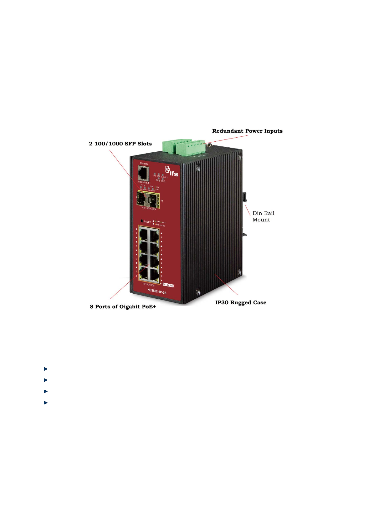
IFS NS3552-8P-2S AND NS3550-2T-8S User Manual
25
1.2 Product Description
Environmentally Hardened Design
The Industrial Switches are equipped with rugged IP30 metal case for stable operation in heavy Industrial demanding
environments. With IP30 industrial case protection, the switches provide a high level of immunity against electromagnetic
interference and h eavy ele ctr ical surges which are usua lly f ound on pla nt floors or in c urb s ide traffic control cabinets. Being able
to operate in wide temperature range from -40 to 75 degrees C, the Industrial Switches can be placed in almost any difficult
environment. The Industrial Switches also allows for either DIN rail or wall mounting for efficient use of cabinet space.
Built-in Unique PoE Functions for Powered Devices Management (NS3552-8P-2S only)
As a managed PoE Switch for surveillance, wireless and VoIP network, the NS3552-8P-2S features three special PoE
Management functions:
PD ALIVE Check
Schedule Power Recycle
SMTP/SNMP Trap Event Alert
PoE Schedule
Intelligent Alive Check for Powered Device
The NS3552-8P-2S can be configured to monitor connected PD (Powered Device) status in real-time via ping action. Once the
PD stops working and responding, the NS3552-8P-2S will resume the PoE port power and bring the PD back to work. It wi ll
greatly enhance the network reliability through the PoE port resetting the PD’s power source and reducing administrator
management burden.
Page 26

IFS NS3552-8P-2S AND NS3550-2T-8S User Manual
26
PoE Schedule for Energy Saving
Under the trend of energy saving worldwide and contributing to environmental protection, the NS3552-8P-2S can effect ively
control the power supply besides its capability of giving high watts power. The built-in “PoE schedule” function helps you to
enable or disable PoE power f eeding for each PoE port dur ing spec ified time interval s and it is a pow erful fun ction to he lp SM B or
Enterprise save power and money.
Digital Input and Digital Output for external Alarm
The Industrial Switches support Digital Input, and Digital Output on its front panel. Thi s external alarm enables users to use
Digital Input to detect, log external device status (such as door intrusion detector), and send event alarm to the administrators.
The Digital Output could be used to alarm the administrators if the Industrial Switches port is link-down, link-up or power-failed.
Page 27

IFS NS3552-8P-2S AND NS3550-2T-8S User Manual
27
Robust Layer 2 Feafures
The Industrial Switches can be programmed for advanced switch management function, such as dynamic port link aggregation,
Q-in-Q VLAN, private V LAN, rapid sp anning tree protocol, layer2 to lay er4 QoS, ban dwidth c ontrol and IG MP/MLD snoop ing. The
NS3552-8P-2S provides 802.1Q tagged VLAN and the VLAN groups allowed will be maximally up to 255. The NS3552-8P-2S
not only allows the operation of a high-speed trunk combining multiple ports, but also supports connection fail-over.
Efficient Management
For efficient man agement, th e Industrial m anaged switch is equipped w ith console, w eb and SNM P manage ment interfaces . With
the built-in web-based management interface, the Industrial Switches o ffer an easy-to-use, platform independent management
and configuration facili ty . The NS3552-8P-2S su pports SNM P and it can be managed via a ny based on st andard of SNM P v1 and
v2 management software. For text-based management mode, the NS3552-8P-2S can be accessed via Telnet and the console
port. Moreover, they also offer remote secure management by supporting SSH, SSL and SNMPv3 connection which can be
encrypted the packet content at each session.
Powerful Security
Page 28

IFS NS3552-8P-2S AND NS3550-2T-8S User Manual
28
The Industri al Sw itches offer comprehensive layer2 to layer4 access contr ol list (ACL) for enfor cing securi ty to the edge. It can be
used to restrict to network access by denying packets based on source and destination IP address, TCP/UDP port number or
defined typical network applications. Its protection mechanism also comprises 802.1x Port-based and MAC-based user and
device authentication. W ith the private VLAN function, communication between edge ports can be prevented to ensure user
privacy. The Industrial Switches also provide DHCP Snooping, IP Source Guard and Dynamic ARP Inspection functions to
prevent IP snooping from attack and discard ARP packets with invalid MAC address. The network administrator can now
construct highly secured corporate networks with considerably less time and effort than before.
Flexibility and Extension Solution
The mini-GBIC slots built in the Industrial Switches supports dual speed that 100Base-FX and 1000Base-SX/LX SFP (Small
Form-factor Pluggable) f iber-optic modu les . N ow t h e a dm ini s tr ator ca n flexibly choose the s uit able SFP trans ceiv er ac cord ing to
not only the transmission distance, but also the transmission speed required. The distance can be extended from 550 meters to
2km (Multi-Mode fiber) up to above 10/20/30/40/50/70 kilometers (Single-Mode fiber or WDM fiber). They are well suited for
applications within the enterpri se dat a cent ers and di stributions.
Perfect Integrafion Solution for Outdoor IP PoE Camera and NVR System
The NS3552-8P-2S provides 8 10/100/1000Mbps 802.3af/at PoE ports an d can of fer suf fici ent PoE pow er for 8 PoE IP camera s
at the same time. In addition, with the 2-Port 100/1000Base-X SFP interfaces, the NS3552-8P-2S can connect to core fiber
switch and send video strea m to NVR and mon itor center . Through the high performance switch archit ecture, the N S3552-8P-2S
facilitates the recorded video files from the 8 PoE IP cameras to be saved in the NVR systems.
Furthermore, the NVR systems can be controlled and monitored both in the local LAN and the remote site via Internet. The
NS3552-8P-2S undoubtedly brings an ideal, secure surveillance syste m at a low er total co st.
Page 29

IFS NS3552-8P-2S AND NS3550-2T-8S User Manual
29
1.3 How to Use This Manual
This User Manual is structured as follows:
Section 2, INSTALLATION
The section explains the functi ons of the Industrial Managed Switch and how to physically install the Industrial
Managed Switch.
Section 3, SWITCH MANAGEMENT
The section contains the information about the software function of the Industrial Managed Switch.
Section 4, WEB CONFIGURATION
The section explains how to manage the Industrial Managed Switch by Web interface.
Section 5, COMMAND LINE INTERFACE
The section describes how to use the Command Line interface (CLI).
Section 6, CLI MODE
The section explains how to manage the Industrial Managed Switch by Command Line interface.
Section 7, SWITCH OPERATION
The chapter explains how to do the switch operation of the Industrial Managed Switch.
Section 8, TROUBLESHOOTING
The chapter explains how to do troubleshooting of the Industrial Managed Switch.
Appendix A
The section contains cab le inf or mat ion of the Industrial Managed Switch.
Appendix B
The section contains Glossary information of the Industrial Managed Switch.
Page 30

IFS NS3552-8P-2S AND NS3550-2T-8S User Manual
30
1.4 Product Features
Physical Port
NS3552-8P-2S
8-Port 10/100/1000Base-T Gigabit Ethernet RJ-45 with IEEE 802.3af / 802.3at PoE Injector
2 100/1000Base-X mini-GBIC/SFP slots, SFP type auto det ecti on
One RJ-45 console interface for basic management and setup
NS3550-2T-8S
2-Port 10/100/1000Base-T Gigabit Ethernet RJ-45
8 100/1000Base-X mini-GBIC/SFP slots, SFP type auto det ecti on
One RJ-45 console interface for basic management and setup NS3552-8P-2S
8-Port 10/100/1000Base-T Gigabit Ethernet RJ-45 with IEEE 802.3af / 802.3at PoE Injector
2 100/1000Base-X mini-GBIC/SFP slots, SFP type auto detection
One RJ-45 console interface for basic management and setup
Power over Ethernet (NS3552-8P-2S ONLY)
Complies with IEEE 802.3af / IEEE 802.3at Power over Ethernet / End-S p an PSE (NS3552-8P-2S)
Complies with IEEE 802.3af Power over Ethernet / End-Span PSE
Up to 8 IEEE 802.3af / 802.3at devices powered (NS3552-8P-2S)
Supports PoE Power up to 15.4watts or 30.8 watts for each PoE port (NS3552-8P-2S)
Auto detect powered device (PD)
Circuit protection prevents power interference between ports
Remote power feeding up to 100m
PoE Management features:
• IEEE 802.3af and IEEE 802.3at mode switch control (NS3552-8P-2S)
• Total PoE power budget control
• Per port PoE function enable/disable
• PoE Admin-mode control
• PoE Port Power feeding priority
• Per PoE port power limit
• PD classification detection
• Temperat ure T hr e sho ld Contr o l
• PoE Usage Threshold Control
• PD Alive Check
• PoE Schedule
• PD Power Recycling Schedule
Industrial Case / Installation
IP30 aluminum metal case protection
DIN rail and wall mount design
48V DC, redundant power with polarity reverse protect function
Supports EFT protection 6000 VDC for power line
Supports 6000 VDC Ethernet ESD protection
-40 to 75 degrees C operating temperature
Page 31

IFS NS3552-8P-2S AND NS3550-2T-8S User Manual
31
Digital Input / Digita l Output
2 Digital Input (DI)
2 Digital Output (DO)
Integrate sensors into auto alarm system
Transfer alarm to IP network via email and SNNP trap
Layer 2 Features
Prevents packet loss with back pressure (half-duplex) and IEEE 802.3x PAUSE frame flow control (full-duplex)
High performance of Store-and-Forward architecture and runt/CRC filtering eliminates erroneous packets to optimize
the network bandwidth
Storm Control supp or t:
− Broadcast / Multicast / Unicast
Supports VLAN
− IEEE 802.1Q Tagged VLAN
− Up to 255 VLANs groups, out of 4094 VLAN IDs
− Provider Bridging (VLAN Q-in-Q) support (IEEE 802.1ad)
− Private VLAN Edge (PVE)
− Protocol-based VLAN
− MAC-based VLAN
− Voice VLAN
Supports Spanning Tree Protocol
− STP, IEEE 802.1D Spanning Tree Protocol
− RSTP, IEEE 802.1w Rapid Spanning Tree Protocol
− MSTP, IEEE 802.1s Multiple Spanning Tree Protocol, spanning tree by VLAN
− BPDU Guard
Supports Link Aggregation
− 802.3ad Link Aggregation Control Protocol (LACP)
− Cisco ether-channel (Static Trunk)
− Maximum 5 trunk groups, up to 8 ports per trunk group
− Up to 16Gbps bandwidth(Duplex Mode)
Provides Port Mirror (1-to-1)
Port Mirroring to monitor the incoming or outgoing traffic on a particular port
Loop protection to avoid broadcast loops
Supports E.R.P.S. (Ethernet Ring Protection Switching)
Quality of Service
Ingress Shaper and Egress Rate Limit per port bandwidth control
8 priority queues on all switch ports
Traffic classification:
− IEEE 802.1p CoS
− IP TOS / DSCP / IP Precedence
− IP TCP/UDP port number
− Typical network appl ic atio n
Page 32

IFS NS3552-8P-2S AND NS3550-2T-8S User Manual
32
Strict priority and Weighted Round Robin (WRR) CoS policies
Supports QoS and In/Out bandwidth control on each port
Traffic-policing policies on the switch port
DSCP remarking
Multicast
Supports IGMP Snooping v1, v2 and v3
Supports MLD Snooping v1 and v2
Querier mode support
IGMP Snooping port filtering
MLD Snooping port filtering
MVR (Multicast VLAN Registration)
Security
IEEE 802.1x Port-based / MAC-based network access authentication
Built-in RADIUS client to co-operate with the RADIUS servers
TACACS+ login users access authentication
RADIUS / TACACS+ users access authentication
IP-based Access Control List (ACL)
MAC-based Access Control List
Source MAC / IP address binding
DHCP Snooping to filter untrusted DHCP messages
Dynamic ARP Inspection discards ARP packets with invalid MAC address to IP address binding
IP Source Guard prev e nt s IP spoofing attacks
Auto DoS rule to defend DoS attack
IP address access management to prevent unauthorized intruder
Management
Switch Management Interfaces
− Console / Telnet Command Line Interface
− Web switch management
− SNMP v1 and v2c switch management
− SSH / SSL and SNMP v3 secure access
Four RMON groups (history, statistics, alarms, and events)
IPv6 IP Address / NTP / DNS management
Built-in Trivial File Transfer Protocol (TFTP) client
BOOTP and DHCP for IP address assignment
Firmware upload/download via HTTP / TFTP
DHCP Relay
DHCP Option82
User Privilege levels control
Page 33

IFS NS3552-8P-2S AND NS3550-2T-8S User Manual
33
NTP (Network Time Protocol)
Link Layer Discovery Protocol (LLDP) Protocol
SFP-DDM (Digital Diagnostic Monit or)
Cable Diagnostic technology provides the mechanism to detect and report potential cabling issues
Reset button for system reboot or reset to factory default
IFS Smart Discovery Utility for deploy management
Page 34

IFS NS3552-8P-2S AND NS3550-2T-8S User Manual
34
NS3550-2T-8S
Hardware Specificati on
Copper Ports
2 10/ 100/1000Base-T RJ-45s
2 10/100/1000Base-T Ethernet interface
SFP/mini-GBIC
Slots
8 1000Base-SX/LX/BX SFP interfaces
Compatible with 100Base-FX SFP
8 100/1000Base-SX/LX mini-GBIC SFP slots
Console
1 x RJ-45-to-RS-232 serial port (115200, 8, N, 1)
Switch
Architecture
Switch Fabric
20Gbps / non-blocking
20Gbps / non-blocking
Throughput
second)
8K entries, automatic source address learning and
ageing
8K entries, automatic source address learning and
ageing
Share Data
Buffer
IEEE 802.3x Pause Frame for Full-Duplex
Back pressure for Half-Duplex
IEEE 802.3x Pause Frame for Full-Duplex. Back
pressure for Half-Duplex
Jumbo Frame
9Kbytes
9Kbytes
> 10 sec: Factory Default
ESD Protection
6KV DC
6KV DC
EFT Protection
6KV DC
6KV DC
Enclosure
IP30 Aluminum Metal Case
IP30 Aluminum Metal Case
Installation
DIN Rail Kit and Wall Mount Kit
DIN Rail Kit and Wall Mount Kit
Removable 6-pin terminal block for power input
Pin 1/2 for Power 1; Pin 3/4 for fault alarm; Pin 5/6 for
GND
One relay output for power failure. Alarm Relay
current carry ability: 1A @ DC 24V
One relay output for power fail. Alarm Relay current
carry ability: 1A @ DC 24V
100mA max.
System:
LNK/ACT (Green)
System:
100 LNK/ACT (Orange)
Dimensions (W
x D x H)
Weight
1684g
1036g
Power
Requirements
Power
At/31.9 watts / 108.78BTU (Full loading without PoE
13.92 Watts / 47.76BTU (Full loading)
1.5 Product Specifications
Product NS3552-8P-2S
Store-and-Forward Store-and-Forward
(packet per
Address Table
Flow Control
Reset Button
Connector
Alarm
DI/DO
14.8Mpps@ 64Bytes packet 14.8Mpps
4Mbits
< 5 sec: System reboot
Power 2
Removable 6-pin terminal block for DI/DO interface
Pin 1/2 for DI 1 & 2; Pin 3/4 for DO 1 & 2; Pin 5/6 for
2 Digital Input (DI): Level 0: -24V~2.1V (±0.1V)
Level 1: 2.1V~24V (±0.1V)
Input Load to 24V DC, 10mA max.
2 Digital Output (DO): Open collector to 24VDC,
< 5 sec: System reboot
> 10 sec: Factory Default
Power 1 (Green)
Power 2 (Green)
Fault Alarm (Green)
Ring (Green)
LED Indicator
Ring Owner (Green)
Per 10/100/1000T RJ-45 Ports:
PoE In-Use (Orange) (NS3552-8P-2S only)
LNK/ACT (Green)
Per SFP Interface:
1000 (Orange)
152 x 107x 72mm 152 x 107x 72mm
DC 48V DC 12 to 48V, AC 24V Power Adapter
Power 1 (Green)
Power 2 (Green)
Fault Alarm (Green)
Ring (Green)
R.O. (Green)
Per 10/100/1000T RJ-45 Ports:
1000 (Green)
10/100, LNK/ACT (Orange)
Per SFP Interface:
1000 LNK/ACT (Green)
Page 35

35
Consumption
function)
function) (NS3552-8P-2S only)
Power Over Ethernet (NS3552-8P-2S only)
PSE
Supply Type
802.3at)
Assignment
Budget
umber of
Class 2 PD
umber of
Class 3 PD
umber of
Class 4 PD
Basic
Interfaces
Secure
Interfaces
Port disable/enable
Power saving mode control
Display each port’s speed duplex mode, link status,
status.
Display each port’s speed duplex mode, link status,
status.
1 to 1 monitor
VLAN groups
802.1Q Tagged Based VLAN ,up to 255 VLAN
Up to 255 VLAN groups, out of 4095 VLAN IDs
Link
Aggregation
IEEE 802.3ad LACP / Static Trunk
Supports 5 group s of 8-Port tr unk suppor t
IEEE 802.3ad LACP / Static Trunk
Support 5 groups of 10-Port trunk support
- Port Number
PoE Standard
IFS NS3552-8P-2S AND NS3550-2T-8S User Manual
306 watts / 1043.46BTU (Full loading with PoE
IEEE 802.3af / IEEE 802.3at Power over Ethernet /
PoE Power
PoE Power
Output
Power Pin
PoE Power
Max. n
Max. n
Max. n
Layer 2 Function
Management
End-Span
Per Port 56V DC, 350mA . Max. 15.4 watts (IEEE
802.3af)
Per Port 56V DC, 590mA. Max. 30 watts (IEEE
1/2(+), 3/6(-)
270W maximum (depending on power input)
8
8
8
Console, Telnet, Web Browser, SNMPv1, v2c Web Browser, Remote Telnet, SNMPv1, v2c
Management
Port
Configuration
Port Status
Port Mirroring
VLAN
SSH, SSL, SNMP v3
Port disable/enable
Auto-Negotiation 10/100/1000Mbps full and half
duplex mode selection
Flow Control disable / enable
Power saving mode control
Flow control status. Auto negotiation status, trunk
TX / RX / Both
802.1Q Tagged Based VLAN, up t o 2 55
Q-in-Q tunneling
Private VLAN Edge (PVE)
MAC-based VLAN
Protocol-based VLAN
Voice VLAN
MVR (Multicast VLAN Registration)
Up to 255 VLAN groups, out of 4094 VLAN IDs
SSH, SSL, SNMP v3
Auto-negotiation 10/100/1000Mbps full and half
duplex mode selection
Auto-detection / Forced 100/1000Mbps SFP Fiber
transceiver speed.
Flow Control disable / enable
Flow control status. Auto negotiation status, trunk
TX / RX / Both
Many to 1 monitor
groups
Q-in-Q tunneling
Private VLAN
MAC-based VLAN
Protocol-based VLAN
Voice VLAN
MVR (Multicast VLAN Registration)
QoS
Traffic classification based, Strict priority and WRR
8-Level priority for switching
Traffic classification based, Strict priority and WRR
8-level priority for switching
- Port Number
Page 36

IFS NS3552-8P-2S AND NS3550-2T-8S User Manual
36
- DSCP/TOS field in IP Packet
- DSCP field in IP Packet
IGMP Snooping
IGMP Querier mode support
MLD Querier mode support
Access Control
Up to 256 entries
Egress: 500Kb~1000Mbps
MAU-MIB
Standards Conformance
Regulation
Compliance
IEC60068-2-6 (Vibration)
IEC60068-2-6 (Vibration)
IEEE 802.3at Power over Ethernet (NS3552-8P-2S)
MLD Snooping
List
Bandwidth
Control
SNMP MIBs
- 802.1p priority
- 802.1Q VLAN tag
IGMP (v1/v2/V3) Snooping, up to 255 multicast
Groups
IGMP Querier mode support
MLD (v1/v2) Snooping, up to 255 multicast Groups
MLD Querier mode support
IP-based ACL / MAC-based ACL
Up to 123 entries
Per port bandwidth control
Ingress: 500Kb~1000Mbps
Egress: 500Kb~1000Mbps
RFC-1213 MIB-II
IF-MIB
RFC-1493 Bridge MIB
RFC-1643 Ethernet MIB
RFC-2863 Interface MIB
RFC-2665 Ether-Like MIB
RFC-2819 RMON MIB (Group 1, 2, 3 and 9)
RFC-2737 Entity MIB
RFC-2618 RADIUS Client MIB
RFC-2933 IGMP-STD-MIB
RFC3411 SNMP-Frameworks-MIB
IEEE 802.1X PAE
LLDP
MAU-MIB
- 802.1p priority
- 802.1Q VLAN tag
IGMP (v1/v2/V3) Snooping, up to 255 multicast
Groups
MLD (v1/v2) Snooping, up to 255 multicast Groups
IP-Based ACL / MAC-Based ACL
Per port bandwidth control
Ingress: 500Kb~1000Mbps
RFC-1213 MIB-II
RFC-2236 IGMPv2
RFC-2710 MLDv1
RFC-3376 IGMPv3
RFC-2879 RMON 1, 2, 3, 9
RFC-1493 Bridge MIB
RFC-1643 Ethernet MIB
RFC-2863 Interface MIB
RFC-2665 Ether-Like MIB
RFC-2819 RMON MIB (Group 1, 2, 3 and 9)
RFC-2737 Entity MIB
RFC-2618 RADIUS Client MIB
RFC3411 SNMP-Frameworks-MIB
IEEE 802.1X PAE
IF-MIB
LLDP
Stability
Testing
Standards
Compliance
FCC Part 15 Class A, CE
IEC60068-2-32 (Free fall)
IEC60068-2-27 (Shock)
IEEE 802.3 10Base-T
IEEE 802.3u 100Base-TX/100Base-FX
IEEE 802.3z Gigabit SX/LX
IEEE 802.3ab Gigabit 1000T
IEEE 802.3x Flow Control and Back pressure
IEEE 802.3ad Port trunk with LACP
IEEE 802.1D Spann ing tree protocol
IEEE 802.1w Rapid spanning tree protocol
IEEE 802.1s Multiple spanning tree protocol
IEEE 802.1p Class of service
IEEE 802.1Q VLAN Tagging
IEEE 802.1x Port Authentication Network Control
IEEE 802.1ab LLDP
IEEE 802.3af Power over Ethernet
FCC Part 15 Class A, CE
IEC60068-2-32 (Free fall)
IEC60068-2-27 (Shock)
IEEE 802.3 10Base-T
IEEE 802.3u 100Base-TX / 100Base-FX
IEEE 802.3z Gigabit SX/LX
IEEE 802.3ab Gigabit 1000T
IEEE 802.3x Flow Control and Back pressure
IEEE 802.3ad Port trunk with LACP
IEEE 802.1D Spanning Tree Protocol
IEEE 802.1w Rapid Spanning Tree Protocol
IEEE 802.1s Multiple Spanning Tree Protocol
IEEE 802.1p Class of service
IEEE 802.1Q VLAN Tagging
IEEE 802.1x Port Authentication Network Control
IEEE 802.1ab LLDP
Page 37

IFS NS3552-8P-2S AND NS3550-2T-8S User Manual
37
RFC 2236 IGMP version 2
Environment
Operating
Temperature
Storage
Temperature
RFC 768 UDP
RFC 793 TFTP
RFC 791 IP
RFC 792 ICMP
RFC 2068 HTTP
RFC 1112 IGMP version 1
-40 ~ 75 degrees C -40 ~ 75 degrees C
-40 ~ 85 degrees C -40 ~ 85 degrees C
Humidity
5 ~ 95% (Non-condensing) 5 ~ 95% (Non-condensing)
Page 38

IFS NS3552-8P-2S AND NS3550-2T-8S User Manual
38
2. INSTALLATION
2.1 Hardware Descriptions
The Managed Switch provides three different running speeds – 10Mbps, 100Mbps and 1000Mbps – in the same Switch and
automatically distinguishes the speed of incoming connection. This section describes the hardware features of the Managed
Switch. For easier management and control of the Managed Switch, familiarize yourself with its display indicators, and ports.
Front panel illustrations in this chapter display the unit’s LED indicators. Before connecting any network device to the Managed
Switch, read this chapter carefully.
2.1.1 Physical Dimensions
Industrial Switches
Dimensions (W x D x H) : 72 x 107 x 152 mm
Page 39
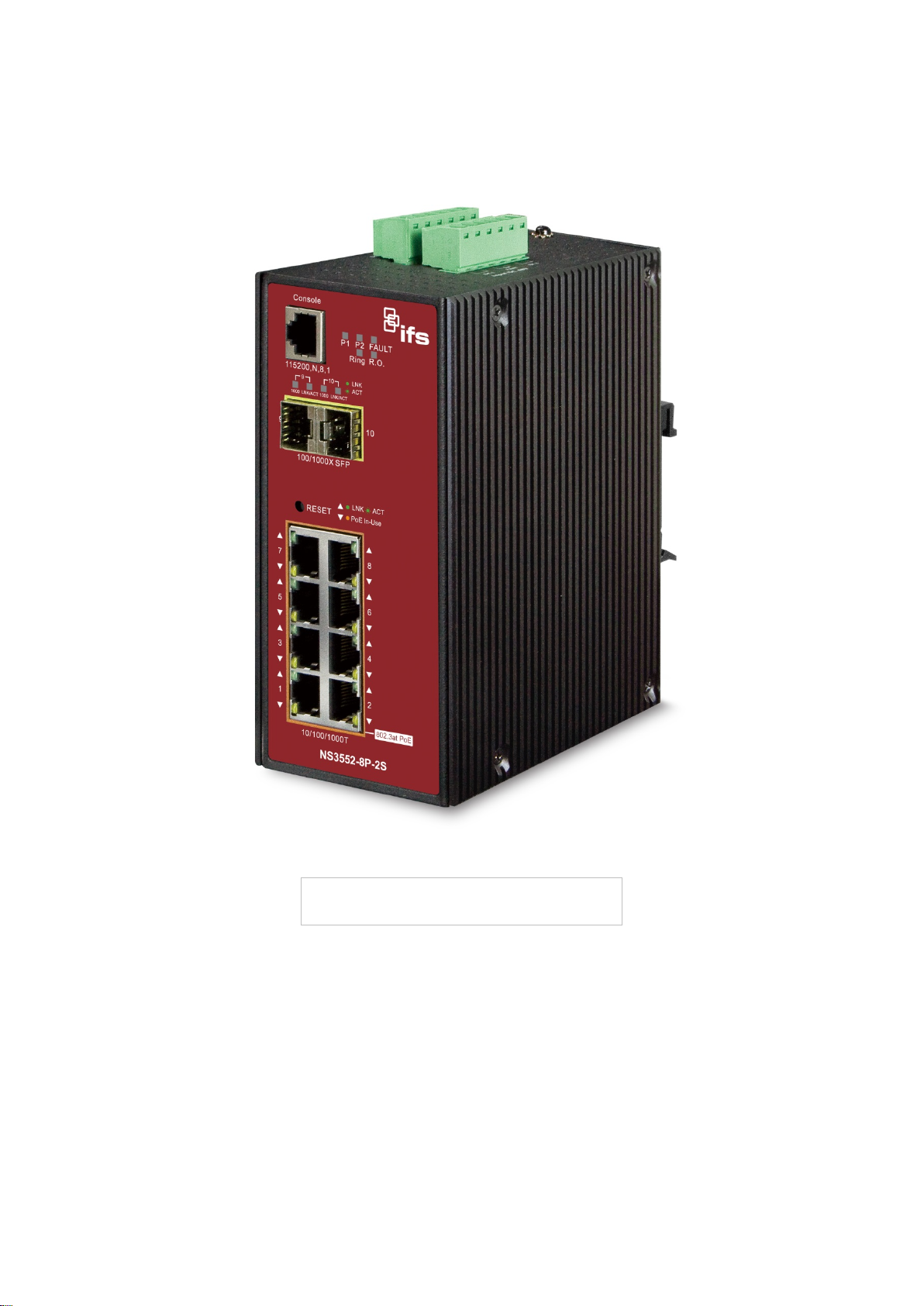
IFS NS3552-8P-2S AND NS3550-2T-8S User Manual
39
2.1.2 Front Panel
Figure 2-1 & 2-2 shows the front panels of Industrial Managed Switch.
Figure 2-2: NS3552-8P-2S Switch Front Panel
Page 40
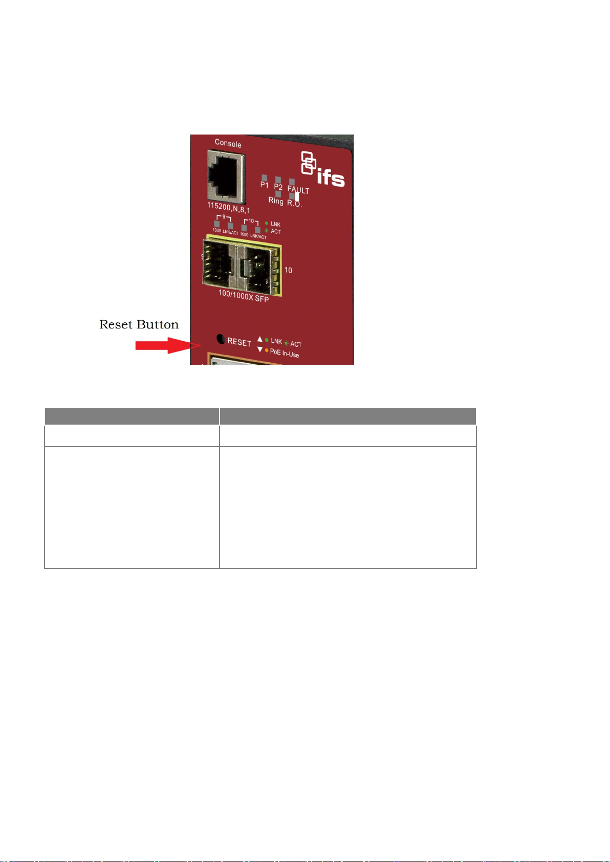
IFS NS3552-8P-2S AND NS3550-2T-8S User Manual
40
Reset Button Pressed and Released
Function
configuration. The Industrial Managed Switch will then reboot
Default Gateway: 192.168.0.254
■ Reset Button
At the left of the front panel, the reset button is designed for rebooting the Industrial Managed Switch without turning off
and on the power. It also can reset the Industrial Managed Switch to factory default mode.
Figure 2-3: Reset button of Industrial Managed Switch
< 5 sec: System Reboot Reboot the Industrial Managed Switch
Reset the Industrial Managed Switch to Factory Default
and load the default settings as below:
> 10 sec: Factory Default
。 Default Username: admin
。 Default Password: admin
。 Default IP address: 192.168.0.100
。 Subnet mask: 255.255.255.0
。
Page 41
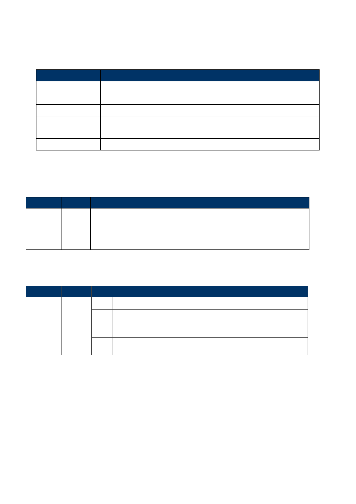
IFS NS3552-8P-2S AND NS3550-2T-8S User Manual
41
Lights to indicate the port is running in 10/100/1000Mbps speed and successfully
Blink: indicates that the switch is actively sending or receiving data over that port.
Lights:
To indicate the port is providing 48/56V DC in-line power.
Off:
To indicate the connected device is not a PoE Powered Device (PD).
2.1.3 LED Ind ic a t ors
System
LED Color Function
P1 Green
P2 Green
Fault Green
Lights to indicate that the Switch is powered on by DC1 input.
Lights to indicate that the Switch is powered on by DC2 input.
Lights to indicate that Switch DC or port has failed.
Ring* Green Lights to indicate that the ERPS Ring has been created successfully.
R.O.* Green Lights to indicate that Switch has enabled Ring Owner.
* = features to be expected in the future
Per 10/100/1000Mbps port with PoE
LED Color Function
10/100/1000
LNK/ACT
PoE In-Use Orange
Green
established.
Per SFP Interface (Port-9, Port-10 mini-GBIC)
LED Color Function
LNK / ACT Green
Light
Blink Indicates that the Switch is actively sending or receiving data over that port.
Light Indicates that the port is successfully connecting to the network at 1000Mbps.
1000 Orange
Off Indicates that the port is successfully connecting to the network at 100Mbps.
Indicates the link through that port is successfully established.
Page 42

IFS NS3552-8P-2S AND NS3550-2T-8S User Manual
42
1 2 3 4 5 6 DC 1
DC 2
+ - +
-
1. The wire gauge for the terminal block should be in the range of 12 ~ 24 AWG.
2.1.4 Wiring the Power Input
The 6-contact terminal block connector on the top panel of the Industrial Managed Switch is used for two DC redundant power
inputs. Please follow the steps below to insert the power wire.
1. Insert positive / negative DC power wires into the contacts 1 and 2 for DC POWER 1, or 5 and 6 for DC POWER 2.
Figure 2-4: NS3552-8P-2S Upper Panel
2. Tighten the wire-clamp screws for preventing the wires from loosening.
Figure 2-5 6-Pin Terminal Block Power Wiring Input
2. When performing any of the procedure s like insert ing the wires or t ighten the wire-cla mp screw s, make
sure the power is OFF to prevent from getting an electric shock.
2.1.5 Wiring the Fault Alarm Contact
The fault alarm contacts are in the middle (3 & 4) of the terminal block connect or as the p ictu re show s below. Inserting the wires,
Page 43

IFS NS3552-8P-2S AND NS3550-2T-8S User Manual
43
Insert the wires into the fault alarm contacts
1. The wire gauge for the terminal block should be in the range of 12 ~ 24 AWG.
the Industrial Managed Switch will detect the fault st atu s of the pow er fai lure, or p ort lin k f ailure (avail able f or manage d m odel).
The following illustration shows an application example for wiring the fault alarm contacts
2. When performing any of the procedures like inserting the wires or tighten the wire-clamp screws, make
sure the power is OFF to prevent from getting an electric shock.
Page 44

IFS NS3552-8P-2S AND NS3550-2T-8S User Manual
44
1 2 3 4 5
6
DI0
DI1
DO0
DO1
GND
GND
2.1.6 Wiring the Digital Input / Output
The 6-contact terminal block connector on the rear panel of NS3552-8P-2S is used for Digital Input and Digital Output. Please
follow the steps below to insert wire.
1. The NS3552-8P-2S offers two DI and DO groups. 1 and 2 are DI groups, 3 and 4 are DO groups and 5 and 6 are GND
(ground).
Figure 2-6 Wiring the Redundant Power Inputs
2. Tighten the wire-clamp screws for preventing the wires from loosening.
Figure 2-7 6-Pin Terminal Block DI / DO Wiring Input
3. There are two Digital Input groups for you to monitor two different devices. The following topology shows how to wire DI0
and DI1.
Page 45

IFS NS3552-8P-2S AND NS3550-2T-8S User Manual
45
Figure 2-8 Wires DI0 and DI1 to Open Detector
4. There are tw o Digit al Output group s for you to sense the Indu strial Sw itches port f ailure or pow er failure and i ssue a hig h or
low signal to external device. The following topology shows how to wire DO0 and DO1.
Figure 2-9 Wires DO0 and DO1 to Open Detector
Page 46

IFS NS3552-8P-2S AND NS3550-2T-8S User Manual
46
2.2 Install the Industrial Managed Switch
This section describes how to install the Industrial Managed Switch and make connections to it. Please read the following
topics and perform the pr ocedures in the or der being pre sented. To install your Industrial Managed S witch on a desktop or shelf,
simply complete the following step s.
In this paragraph, we will describe how to install the Industrial Managed Switch and the installation points attended to it.
2.2.1 Installation Steps
1. Unpack the Industrial Managed Switch
2. Check if the DIN-Rail is screwed on the Industrial Managed Switch or not. If the DIN-Rail is not screwed on the
Industrial Managed Switch, please refer to DIN-Rail Mounting section for DIN-Rail installation. If users w ant to wall-mount
the Industrial Managed Switch, please refer to the Wall Mount Plate Mounting section for wall-mount plate installation.
3. To hang the Industrial Managed Switch on the DIN-Rail track or wall.
4. Power on the Industrial Managed Switch. Please refer to the Wiring the Power Inputs section for knowing the
information about how to wir e the pow er . T he power LED on t he Industrial Managed Switch will light up. Pl ease refer t o th e
LED Indicators section for indicat ion of LED ligh t s.
5. Prepare the twisted-pair, straight through Category 5 cable for Ethernet connection.
6. Insert one side of RJ-45 cabl e ( cat eg ory 5) into the Industrial Managed Switch Ethernet port (RJ-45 port) and another
side of RJ-45 cable (category 5) to the network device’s Ethernet port (RJ-45 port), ex: Switch PC or Server. The UTP port
(RJ-45) LED on the Industrial Managed Switch will light up when the cable is connected with the network device. Please
refer to the LED Indicators section for LED light indication.
Make sure that the connected network devices support MDI/MDI-X if it does not support, or
use the crossover category-5 cable.
7. When all connections are set and LED lights all show normal, the installation is completed.
Page 47

IFS NS3552-8P-2S AND NS3550-2T-8S User Manual
47
2.2.2 DIN-Rail Mounting
This section describes how to install the Industrial Managed Switch.
There are two methods to install the Industrial Managed Switch -- DIN-Rail Mounting and Wall Mount Plate Mounting. Please
read the following topics and per form the proc edures in the order being presented.
In the installation steps below, this Manual use NS3550-2T-8S (IFS 8 Port Industrial Gigabit Switch) as the
example. However, the steps for IFS Industrial Gigabit PoE+ Switch are similar.
Step 1: Screw the DIN-Rail on the Industrial Managed Switch.
Step 2: Lightly insert the bottom of the switch into the track.
Page 48

IFS NS3552-8P-2S AND NS3550-2T-8S User Manual
48
Step 3: Check if the DIN-Rail is tightly on the track .
Please refer to following procedures to remove the Industrial Managed Switch from the track.
Step 1: Lightly pull out the bottom of the switch for removing it from the track.
Page 49

IFS NS3552-8P-2S AND NS3550-2T-8S User Manual
49
8 Port Industrial G igabit Sw itch) as
2.2.3 Wall Mount Plate Mounting
To install the Industrial Managed Switch on the wall, please follow the instructions below.
In the instal lation steps below, this Manual use NS3550-2T-8S (IFS
the example. However, the steps for IFS Industrial Gigabit PoE+ Switch are similar.
Step 1: To remove the Industrial Managed S witch from the DIN-Rail, use the screwdriver to loosen the screw s and remo ve the
DIN-Rail.
Step 2: Place the wal l mount plate on the rear panel of the Industrial Managed Switch.
Step 3: Use the screws to screw the wall mount plate on the Industrial Managed Switch.
Step 4: Use the hook holes at the corners of the wall mount plate to hang the Industrial Managed Switch on the wall.
Step 5: To remove the wall mount plate, reverse steps above.
Page 50

IFS NS3552-8P-2S AND NS3550-2T-8S User Manual
50
Port Type
Cable Type
Connector
10Base-T
Cat 3, 4, 5, 2-pair
RJ-45
100Base-TX
Cat.5 UTP, 2-pair
RJ-45
1000Base-T
Cat.5/5e/6 UTP, 2-pair
RJ-45
100Base-FX
50 / 125µm or 62.5 / 125µm multi-mode 9 / 125µm single-mode
LC (Multi / Single mode)
1000Base-SX/LX
50 / 125µm or 62.5 / 125µm multi-mode 9 / 125µm single-mode
LC (Multi / Single mode)
2.3 Cabling
10/100/1000Base-T and 100Base-FX / 1000Base-SX/LX
All 10/100/1000Base-T ports come with Auto-Negotiation capability. They automatically support 1000Base-T, 100Base-TX
and 10Base-T networks. Users only need to plug a working network device into one of the 10/100/1000Base-T ports, and
then turn on the Industrial Managed Switch. The port will automatically run in 10Mbp s, 20M bps, 100M bps or 200M bps and
1000Mbps or 2000Mbp s after the negotiation with the connected device.
The Industrial Managed Switch has eight SFP interfaces that support 100/1000Mbps dual speed mode (optional
multi-mode/ single-mode 100Base-FX/1000Base-SX/LX SFP module)
Cabling
Each 10/100/1000Base-T port use s RJ-45 sockets -- similar t o phone j acks -- for connection of unshielded twisted-pair cable
(UTP). The IEEE 802.3/802.3u 802.3ab Fast/Gigabit Ethernet standard req uires Categor y 5 UTP for 100M bps 100Base-TX.
10Base-T networks can use Cat.3, 4, 5 or 1000Base-T use 5/5e/6 UTP (see table below). Maximum distance is 100meters
(328 feet). T he 100Base-FX/1000Base-SX/LX SFP slot is us ed as LC connector with opt ional SF P mod ule. Pl ease see table
below and know more about the cable specifications.
Any Ethernet devices like hubs/PCs can connect to the Industrial Managed Switch by using straight-through wires. The
two 10/100/1000Mbps ports are auto-MDI/MDI-X , which can be used on straight-through or crossover cable.
Page 51
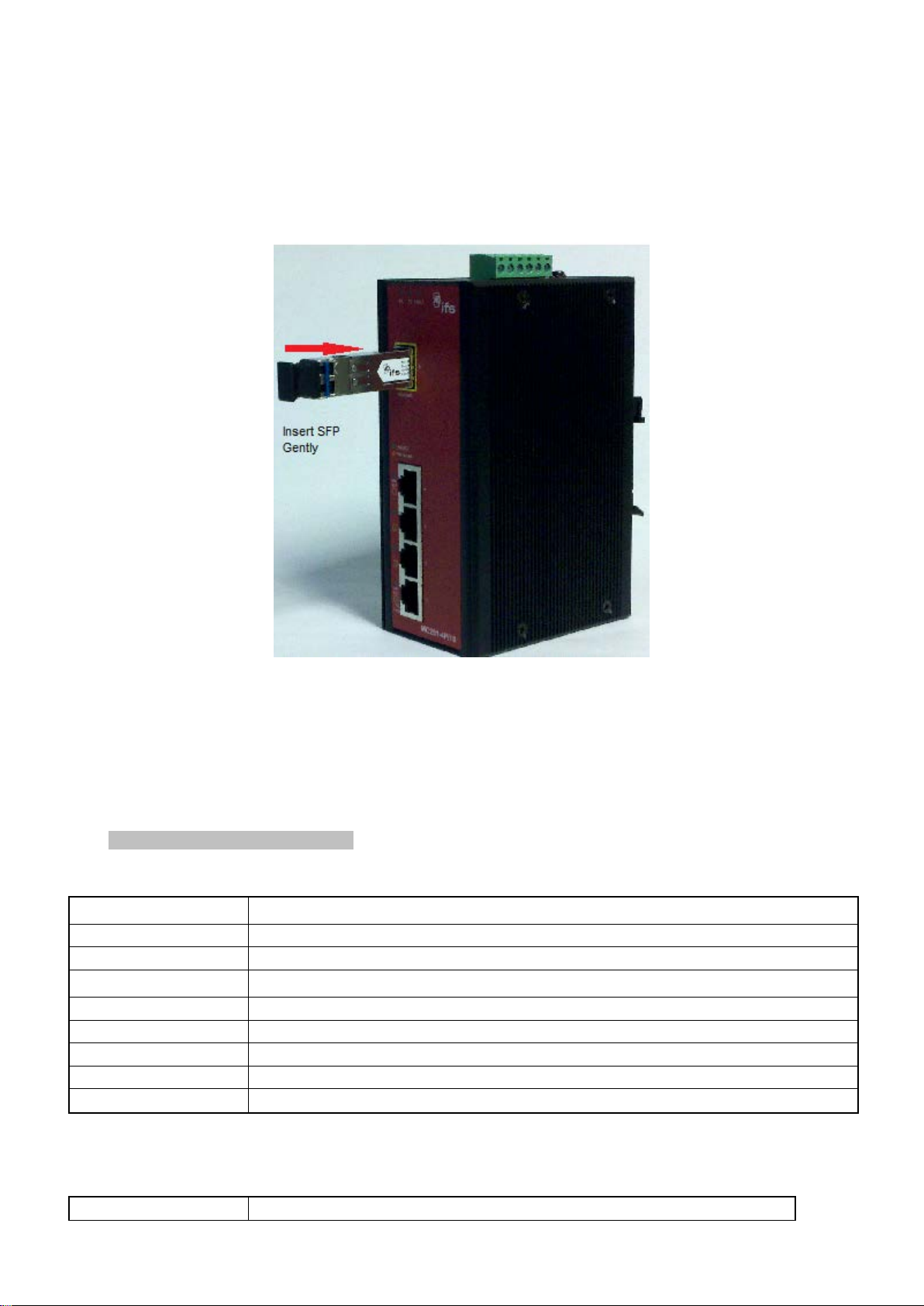
IFS NS3552-8P-2S AND NS3550-2T-8S User Manual
51
S30-1SLC/A-10
SFP, LC Connector, Single Mode, Gigabit, 1 fiber, 1310nm/1550nm, 10km , A End
S30-1SLC/A-20
SFP, LC Connector, Single Mode, Gigabit, 1 fiber, 1310nm/1550nm, 20km, A End
S30-1SLC/A-60
SFP, LC Connector, Single Mode, Gigabit, 1 fiber, 1310nm/1550nm, 60km, A End
S30-1SLC/B-10
SFP, LC Connector, Single Mode, Gigabit, 1 fiber, 1550nm/1310nm, 10km , B End
S30-1SLC/B-20
SFP, LC Connector, Single Mode, Gigabit, 1 fiber, 1550nm/1310nm, 20km, B End
S30-1SLC/B-60
SFP, LC Connector, Single Mode, Gigabit, 1 fiber, 1550nm/1310nm, 60km, B End
S30-2MLC
SFP, LC Connector, Multi-Mode, Gigabit, 2 fiber,850nm/850nm, 550m
S30-2MLC-2
SFP, LC Connector, Multi-Mode, Gigabit, 2 fiber,1310nm/1310nm, 2km
S30-2SLC-10
SFP, LC Connector, Single Mode, Gigabit, 2 fiber,1310nm/1310nm, 10km
S30-2SLC-30
SFP, LC Connector, Single Mode, Gigabit, 2 fiber,1310nm/1310nm, 30km
2.3.1 Installing the SFP Transceiver
The sections describe how to insert an SFP transceiver into an SFP slot. The SFP transceivers are hot-pluggable and
hot-swappable. You can plug-in and out the transceiver to/from any SFP port without having to power down the Industrial
Managed Switch as the Figure 2-9 appears.
Figure 2-9: Plugging in the SFP Transceiver
Approved IFS SFP Transceivers
IFS Industrial Managed Switch supports 100/1000 dual mode with both Single mode and M ulti -mode SFP transceiver.
The following list of approved IFS SFP transceivers is correct at the time of publication:
Gigabit SFP Transceiver Modules
Page 52

IFS NS3552-8P-2S AND NS3550-2T-8S User Manual
52
S30-2SLC-70
SFP, LC Connector, Single Mode, Gigabit, 2 fiber,1550nm/1550nm, 70km
S30-RJ
SFP, RJ-45, Gigabit, 100m
S35-2MLC
SFP, LC Connector, Multi-Mode, Gigabit, 2 fiber,850nm/850nm, 550m,
S35-2SLC-10
SFP, LC Connector, Single Mode, Gigabit, 2 fiber,1310nm/1310nm, 10km,
S35-2SLC-30
Hardened -40~75°C
S35-2SLC-70
Hardened -40~75°C
SFP
Hardened -40~75°C
Hardened -40~75°C
SFP, LC Connector, Single Mode, Gigabit, 2 fiber,1310nm/1310nm, 30km,
SFP, LC Connector, Single Mode, Gigabit, 2 fiber,1550nm/1550nm, 70km,
Fast Ethernet SFP Transceiver ModulesError! Not a valid link.
1. It is recommended to use IFS SFPs on the Industrial Managed Switch. If you insert an
transceiver that is not supported, th e Industrial Managed Switch will not recognize it.
2. Please choose the SFP transceiver which is appropriate for the operating environment.
1000Base-SX/LX:
Before connecting the other switches, workstation or media converter.
1. Make sure both sid es of the SFP transceiver are with the same media type, for example, 1000Base-SX to 1000Base-SX,
1000Bas-LX to 1000Base-LX.
2. Check the fiber-opt ic cab le typ e that matches the SFP transceiver model.
To connect to 1000Base-SX SFP transceiver, use the multi-mode fiber cable with one side being the male duplex LC
connector type.
To connect to 1000Base-LX SF P tr a ns ceiv er, use the single-mode fiber cable with one s ide bei ng the male dup lex LC
connector type.
Connect the fiber cable
1. Attach the duplex LC connector on the network cable into the SFP transceiver.
2. Connect the other end of the cable to a device – switches with SFP installed, fiber NIC on a workstation or a media
converter.
3. Check the LNK /AC T LED of the SFP slot on the front of the Industrial Managed Switch. Ensure that the S FP transceiver
is operating correctly.
100Base-FX:
Before connecting the other switches, workstation or media converter.
1. Make sure both sides of the SFP transceiver are with the same media type or WDM pair; for example, 100Base-FX to
100Base-FX, 100Base-BX20-U to 100Base-BX20-D.
2. Check the fiber-opt ic cab le typ e that matches the SFP transceiver model.
To connect to MFB-FX SFP transceiver, use the multi-mode fiber cable with one side being the male duplex LC
connector type.
To connect to MFB-F20/F40/F60/FA20/FB20 SFP transc eiver , use the single-mode fiber cable with one side be ing the
male duplex LC connector type.
Connect the fiber cable
1. Attach the duplex LC connector on the network cable into the SFP transceiver.
2. Connect the other end of the cable to a device – switches with SFP installed, fiber NIC on a workstation or a media
converter.
Page 53

IFS NS3552-8P-2S AND NS3550-2T-8S User Manual
53
Never pull out the module without lifting up the lever of the module and turning it to a
horizontal position. Directly pulling out the module could damage the module and the SFP
3. Check the LNK/ACT LED of the SFP slot of the switch/conv erter. Ensure that the SFP transceiver is operating correctly.
4. Check the Link mode of the SFP port if the link fails. Co works w ith some fiber-NICs or media converters. Set the Link mode
to “100 Force” when needed.
2.3.2 Remove the Module
1. Make sure ther e i s no netw ork activ ity by chec king w ith t he net work admin istrator, or through the management interfa ce of
the switch/converter (if available) to disable the port in advance.
2. Remove the Fiber Optic Cable gently.
3. Lift up the lever of the MGB/MFB module and turn it to a horizontal position.
4. Pull out the module gently through the lever.
Figure 2-10: How to Pull Out the SFP Transceiver Module
module slot of the Managed Switch.
Page 54

IFS NS3552-8P-2S AND NS3550-2T-8S User Manual
54
3. SWITCH MANAGEMENT
This chapter explains the methods that you can use to configure management access to the Industrial M anaged Switch. It
describes the types of management applicati ons and the co m muni cat ion and ma nage men t protocols that deliver data betw een
your management device ( w or kstation or personal computer) and the system. It al so con t ains information about port connection
options.
This chapter covers the following topics:
Requirements
Management Access Overview
Remote Telnet Access
Web Management Access
SNMP Access
Standards, Protocols, and Related Reading
3.1 Requirements
Workstations of subscribers running Windows XP/2003, Vista, Windows 7, MAC OS X, Linux, Fedora, Ubuntu or
other platform compatible with TCP/IP protocols.
The Workstation is inst all ed with Ethernet NIC (Network Interface Card)
Ethernet Port connection
• Network cables - Use standard network (UTP) cables with RJ45 connectors.
• The above Workstation is installed with WEB Browser and JAVA runtime environment Plug-in
It is recommended to use Internet Explorer 7.0 or above to access Industrial Managed Switch.
Page 55

IFS NS3552-8P-2S AND NS3550-2T-8S User Manual
55
Method
Advantages
Disadvantages
Remote
• Text-based
• Can be accessed from any location
• Security can be compromised (hackers need
Web Browser
• Ideal for configuring the switch remotely
• Most visually appealing
• Security can be compromised (hackers need
SNMP Agent
• Communicates with switch functions at
• Requires SNMP manager software
only know the community name)
3.2 Management Access Overview
The Industrial Managed Switch gives you the flexibility to access and manage it using any or all of the following methods:
Remote Telnet Interface
Web browser Interface
An external SNMP-based network management application
The Remote Telnet and Web browser interface support are embedded in the Industrial Managed Switch software and are
available for immediate use. Each of these management methods has their own advantages. Table 3-1 compares the three
management methods.
Telnet
• Telnet functionality built into Windows
XP/2003, Vista, Windows 7 operating
systems
• Compatible with all popular browsers
• Can be accessed from any location
the MIB level
• Based on open standards
Table 3-1: Management Methods Comparaison
only know the IP address)
only know the IP address and subnet mask)
• May encounter lag times on poor connections
• Least visually appealing of all three methods
• Some settings require calculations
• Security can be compromised (hackers need
Page 56
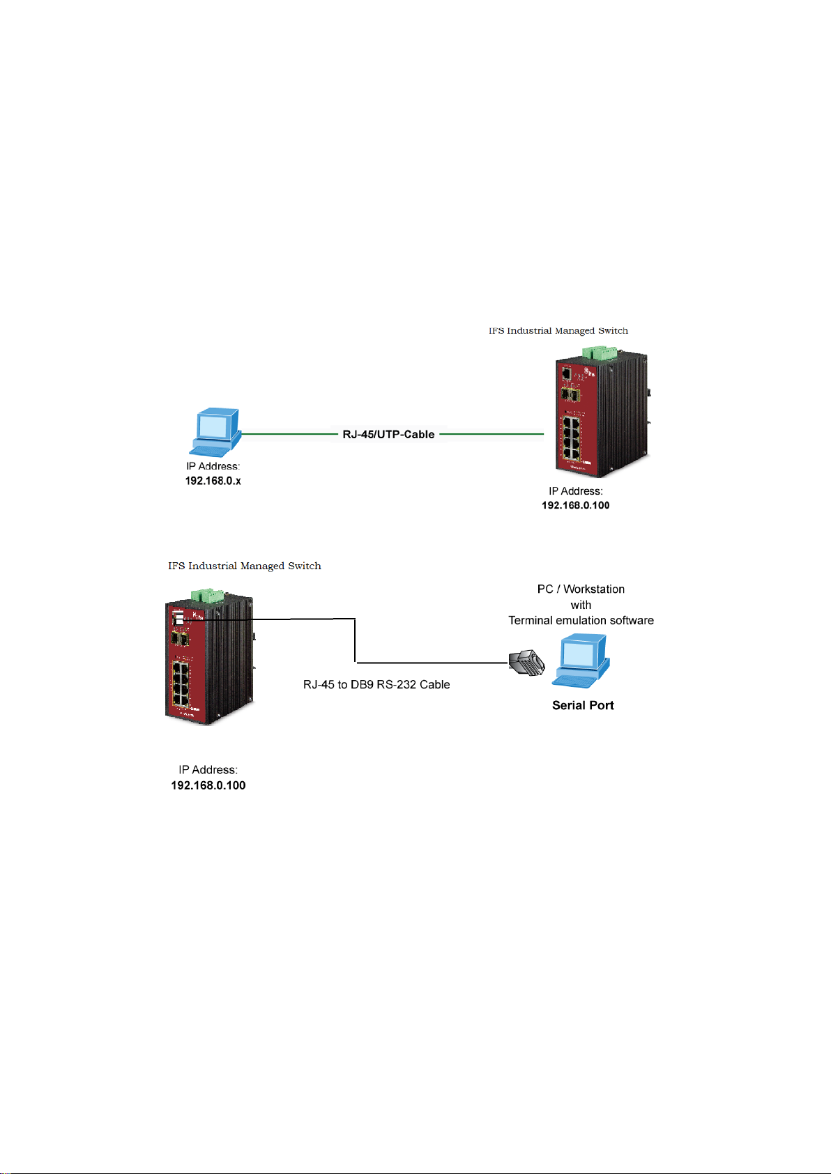
IFS NS3552-8P-2S AND NS3550-2T-8S User Manual
56
3.3 CLI Mode Management
There are two ways for CLI mo de manageme nt, one is remo te telnet, an d the other is operat ing from cons ole port. Re mote telnet
is an IP-based protocol, and console port is for user to operate the Industrial Managed Switch on local only; however their
operation is the same.
The comman d line user int erface is for performing system administration, such as displayin g statisti cs or changing option setting s.
Using this method, you can access the Industrial Managed Switch remote telnet interface from personal computer or
workstation in the same Ethernet environment as long as you know the current IP address of the Industrial Managed Switch.
Figure 3-1: Remote Telnet and Console Port Interface Management
In Windows system, you may click “Start” and then choose “Acessories” and “Command Prompt”. Please input “telnet
192.168.0.100” and press “enter’ from your keyboard. The following scre en (see Fig ur e 3-2) wil l appear.
Page 57

IFS NS3552-8P-2S AND NS3550-2T-8S User Manual
57
Figure 3-2: Remote Telnet Interface Main Screen of Industrial Managed Switch
For more information about using the Remote Telnet interface, refer to Chapter 5 Remote Telnet Interface Management.
Page 58

IFS NS3552-8P-2S AND NS3550-2T-8S User Manual
58
3.4 Web Management
The Industrial Managed Switch of fers m anageme nt fea tures that a llow users to man age the Industrial Managed Switch from
anywhere on the networ k through a st andard brow ser such as M icrosoft Interne t Explorer. After you set up your IP address for th e
Industrial Managed Switch, you can access the Industrial Managed Switch’s Web interf ace applicat ions directly in your Web
browser by entering the IP address of the Industrial Managed Switch.
Figure 3-3: Web Management
You can then use your Web browser to list and manage the Industrial Managed Switch configurati on parameters from one
central location; the Web Management requires Microsoft Internet Explorer 7.0 or later.
.
Figure 3-4: Web Main Screen of Industrial Managed Switch
Page 59

IFS NS3552-8P-2S AND NS3550-2T-8S User Manual
59
3.5 SNMP-Based Network Management
You can use an external SNMP-based application to configure and manage the Industrial Managed Switch, such as SNMP
Network Manager , H P O pen view Netw ork Node Managem ent (NNM ) or What’s Up G old. This management method requires the
SNMP agent on the Industrial Managed Switch and the SNMP Network Management Station to use the same community
string. This management method, in fa ct, uses two comm unity strings: th e get community string and the set community string.
If the SNMP Net-work management Station only knows the set community stri ng, it can rea d and w rite to the M IB s. How ever, if it
only knows the get community string, it can only read MIBs. The default getting and setting community strings for the Industrial
Managed Switch are public.
Figure 3-5: SNMP Management
Page 60

IFS NS3552-8P-2S AND NS3550-2T-8S User Manual
60
By default, IE7.0 or later version does not allow Java Applets to open sockets. The user has to
4. WEB CONFIGURATION
This section introduces the configuration and functions of the Web-Based management.
About Web-based Management
The Industrial Managed Switch off ers mana gement f eature s that a llow user s to manag e t he Industrial Managed Switch from
anywhere on the network through a standard browser such as Microsoft Internet Explorer.
The Web-based Management supports Internet Explorer 7.0. It is based on Java Applets with an aim to reduce network
bandwidth consumption, enhance access speed and present an easy viewing screen.
explicitly modify the brows er setting to enable Java Applets to use network ports.
The Industrial Managed Switch can be configured through an Ethernet connection, making sure the manager PC must be set
on the same IP subnet address as the Industrial Managed Switch.
For example, the defau lt IP ad dress of the Industrial Managed Switch is 192.168.0.100, then the manager PC should be set at
192.168.0.x (where x is a number between 1 and 254, except 100), and the default subnet mask is 255.255.255.0.
If you have changed the default IP address of the Industrial Managed Switch to 192.168.1.1 with subnet mask 255.255.255.0
via console, then the manager PC should be set at 192.168.1.x (where x is a number between 2 and 254) to do the relative
configuration on manager PC.
Figure 4-1-1: Web Management
Gentlogging on the Industrial Managed Switch
1. Use Internet Explorer 7.0 or above Web browser. Enter the factory-default IP addres s to ac ces s the Web interface. The
Page 61

IFS NS3552-8P-2S AND NS3550-2T-8S User Manual
61
factory-default IP Address is shown as follows:
http://192.168.0.100
2. When the following login screen appears, please enter the default username "admin" with password “admin” (or the
username/password you have changed via console) to login the main screen of Industrial Managed Switch. The login
screen in Figure 4-1-2 appears.
Figure 4-1-2: Login Screen
Default User name: admin
Default Password: admin
After entering the username and password, the main screen appears as Figure 4-1-3.
Page 62

IFS NS3552-8P-2S AND NS3550-2T-8S User Manual
62
1. It is recommended to use Internet Explorer 7.0 or above to access Industrial Managed
button. You need
4. Only accept command in lowercase letter under web interface.
Figure 4-1-3: Default Main Page
Now, you can use the Web management interface to continue the switch management or manage the Industrial Managed
Switch by Web interface. The Switch Menu on the left of the web page lets you access all the commands and statistics the
Managed Switch provides.
Switch.
2. The changed IP ad dress take s effect immediately after cli cking on the Save
to use the new IP address to access the Web interface.
3. For security reason, please change and memorize the new password after this first setup.
Page 63

IFS NS3552-8P-2S AND NS3550-2T-8S User Manual
63
State
Disabled
Link Down
Link Up
PoE On
4.1 Main Web Page
The Industrial Managed Switch provides a Web-based browser interface for conf igurin g and managi ng it. T his interfa ce allow s
you to access the Industrial Managed Switch using the Web browser of your choice. This chapter describes how to use the
Industrial Managed Switch’s Web browser interface to configure and manage it.
Main Functions Menu
Copper Port Link Status
SFP Port Link Status
Figure 4-1-4: Main Page
Panel Display
The web agent displays an image of the Industrial Managed Switch’s ports. The Mode can be set to display different
information for the ports, including Link up or Link down. Clicking on the image of a port opens the Port Statistics page.
The port states are illustrated as follows:
RJ-45 Ports
SFP Ports
Not Supported
 Loading...