

Page 1

IFS NS3550-24T/4S User
Manual
P/N 1072569 • REV 00.07 • ISS 25JAN13
Page 2

Copyright
Trademarks and patents
Intended use
Manufacturer
Certification
FCC compliance
ACMA compliance Notice! This is a Class A product. In a domestic environment this
Canada
European Union directives
Contact information
Contact support
© 2013 UTC Fire & Security Americas Corporation, Inc.
Interlogix is part of UTC Climate Controls & Security, a unit of United
Technologies Corporation. All rights reserved.
The IFS NS3550-24T/4S and logo are trademarks of United Technologies.
Other trade names used in this document may be trademarks or
registered trademarks of the manufacturers or vendors of the respective
products.
Use this product only for the purpose it was designed for; refer to the
data sheet and user documentation for details. For the latest product
information, contact your local supplier or visit us online at
www.interlogix.com.
UTC Fire & Security Americas Corporation, Inc.
2955 Red Hill Avenue
Costa Mesa, CA 92626-5923, USA
EU authorized manufacturing representative:
UTC Fire & Security B.V., Kelvinstraat 7,
6003 DH Weert, The Netherlands
N4131
This equipment has been tested and found to comply with the limits for a
Class A digital device, pursuant to part 15 of the FCC Rules. These limits
are designed to provide reasonable protection against harmful
interference when the equipment is operated in a commercial
environment. This equipment generates, uses, and can radiate radio
frequency energy and, if not installed and used in accordance with the
instruction manual, may cause harmful interference to radio
communications.
You are cautioned that any changes or modifications not expressly
approved by the party responsible for compliance could void the user's
authority to operate the equipment.
product may cause radio interference in which case the user may be
required to take adequate measures.
This Class A digital apparatus complies with Canadian ICES-003.
Cet appareil numérique de la classe A est conforme á la norme
NMB-003du Canada.
2004/108/EC (EMC Directive): Hereby, UTC Fire & Security Americas
Corporation, Inc. declares that this device is in compliance with the
essential requirements and other relevant provisions of Directive
2004/108/EC.
2002/96/EC (WEEE directive): Products marked with this symbol cannot
be disposed of as unsorted municipal waste in the European Union. For
proper recycling, return this product to your local supplier upon the
purchase of equivalent new equipment, or dispose of it at designated
collection points. For more information see: www.recyclethis.info.
For contact information see our Web site: www.interlogix.com
www.interlogix.com/customer support
.
2
Page 3

NS3550-24T/4S User Manual
TABLE OF CONTENTS
IFS NS3550-24T/4S User Manual............................................................................................. 1
INTRODUCTION...................................................................................................................... 18
Packet Contents...............................................................................................................................................18
Product Description.........................................................................................................................................18
How to Use This Manual..................................................................................................................................20
Product Features..............................................................................................................................................21
Product Specification ......................................................................................................................................24
INSTALLATION ....................................................................................................................... 26
Hardware Description......................................................................................................................................26
Switch Front Panel .......................................................................................................................................................26
LED Indications ............................................................................................................................................................27
Switch Rear Panel........................................................................................................................................................28
Install the Switch..............................................................................................................................................29
Desktop Installation ......................................................................................................................................................29
Rack Mounting .............................................................................................................................................................30
Installing the SFP transceiver.......................................................................................................................................31
Wiring the Power Input .................................................................................................................................................34
Wiring the Digital Input / Output....................................................................................................................................35
SWITCH MANAGEMENT........................................................................................................38
Requirements ...................................................................................................................................................38
Management Access Overview.......................................................................................................................39
Administration Console...................................................................................................................................39
Web Management.............................................................................................................................................41
SNMP-Based Network Management...............................................................................................................42
WEB CONFIGURATION.......................................................................................................... 43
Main Web Page.................................................................................................................................................46
System...............................................................................................................................................................48
System Information ......................................................................................................................................................49
3
Page 4

IP Configuration............................................................................................................................................................50
IPv6 Configuration........................................................................................................................................................51
Users Configuration.........................................................................................................................................52
Users Privilege Levels..................................................................................................................................................56
NTP Configuration........................................................................................................................................................58
UPnP Configuration......................................................................................................................................................58
DHCP Relay .................................................................................................................................................................60
DHCP Relay Statistics ..................................................................................................................................................62
CPU Load.....................................................................................................................................................................64
System Log ..................................................................................................................................................................65
Detailed Log .................................................................................................................................................................66
Remote Syslog .............................................................................................................................................................67
SMTP Configure...........................................................................................................................................................67
Web Firmware Upgrade ...............................................................................................................................................69
TFTP Firmware Upgrade..............................................................................................................................................70
Configuration Backup ...................................................................................................................................................71
Configuration Upload....................................................................................................................................................73
Digital input/output........................................................................................................................................................74
Fault Alarm ...................................................................................................................................................................75
Factory Default .............................................................................................................................................................77
System Reboot.............................................................................................................................................................78
Simple Network Management Protocol..........................................................................................................79
SNMP Overview ...........................................................................................................................................................79
SNMP System Configuration........................................................................................................................................80
SNMP System Information Configuration.....................................................................................................................81
SNMP Trap Configuration.............................................................................................................................................81
SNMPv3 Configuration.................................................................................................................................................83
SNMPv3 Communities Configuration ....................................................................................................................83
SNMPv3 Users Configuration ...............................................................................................................................83
SNMPv3 Groups Configuration .............................................................................................................................85
SNMPv3 Views Configuration ...............................................................................................................................85
SNMPv3 Accesses Configuration..........................................................................................................................86
Port Management.............................................................................................................................................88
Port Configuration ........................................................................................................................................................88
Port Statistics Overview................................................................................................................................................90
Port Statistics Detail......................................................................................................................................................91
SFP Module Information...............................................................................................................................................93
Port Mirroring Configuration .........................................................................................................................................94
Link Aggregation..............................................................................................................................................97
Static Aggregation Configuration ..................................................................................................................................99
4
Page 5

NS3550-24T/4S User Manual
LACP Configuration....................................................................................................................................................101
LACP System Status ..................................................................................................................................................102
LACP Port Status........................................................................................................................................................104
LACP Port Statistics ...................................................................................................................................................105
VLAN................................................................................................................................................................107
VLAN Overview ..........................................................................................................................................................107
IEEE 802.1Q VLAN ....................................................................................................................................................107
VLAN Basic Information ............................................................................................................................................. 111
VLAN Port Configuration ............................................................................................................................................112
VLAN Membership Configuration ............................................................................................................................... 116
VLAN Membership Status for User Static...................................................................................................................117
VLAN Port Status for User Static................................................................................................................................118
Port Isolation Configuration ........................................................................................................................................119
Private VLAN Membership Configuration ...................................................................................................................121
VLAN setting example:...............................................................................................................................................123
Two separate 802.1Q VLAN................................................................................................................................123
VLAN Trunking between two 802.1Q aware switch.............................................................................................127
Port Isolate ..........................................................................................................................................................128
Spanning Tree Protocol.................................................................................................................................131
Theory ........................................................................................................................................................................131
STP Bridge Configuration...........................................................................................................................................137
Bridge Status..............................................................................................................................................................139
CIST Port Configuration .............................................................................................................................................139
MSTI Priorities............................................................................................................................................................142
MSTI Configuration ....................................................................................................................................................143
MSTI Ports Configuration ...........................................................................................................................................144
Port Status..................................................................................................................................................................146
Port Statistics..............................................................................................................................................................147
Multicast..........................................................................................................................................................148
IGMP Snooping ..........................................................................................................................................................148
IGMP Snooping Configuration....................................................................................................................................153
IGMP Port Related Configuration ...............................................................................................................................153
VLAN Configuration....................................................................................................................................................155
Port Group Filtering ....................................................................................................................................................156
IGMP Snooping Status ...............................................................................................................................................157
MVR Configuration .....................................................................................................................................................159
MVR Status ................................................................................................................................................................161
Quality of Service...........................................................................................................................................163
Understand QOS........................................................................................................................................................163
5
Page 6

QCL Configuration Wizard..........................................................................................................................................164
Set up Policy Rules .............................................................................................................................................165
Set up Typical Network Application Rules ...........................................................................................................166
Set up ToS Precedence Mapping........................................................................................................................169
Set up VLAN Tag Priority Mapping......................................................................................................................170
QoS Control List Configuration...................................................................................................................................171
QoS Control Entry Configuration.........................................................................................................................172
Port QoS Configuration ..............................................................................................................................................173
Bandwidth Control ......................................................................................................................................................175
Storm Control Configuration .......................................................................................................................................177
QoS Statistics.............................................................................................................................................................178
DSCP Remarking .......................................................................................................................................................179
Voice VLAN Configuration..........................................................................................................................................181
Voice VLAN OUI Table ...............................................................................................................................................183
Access Control Lists......................................................................................................................................184
Access Control List Status..........................................................................................................................................185
Access Control List Configuration ..............................................................................................................................186
ACE Configuration......................................................................................................................................................187
ACL Ports Configuration.............................................................................................................................................193
ACL Rate Limiter Configuration..................................................................................................................................194
Authentication................................................................................................................................................196
Understanding IEEE 802.1X Port-Based Authentication ............................................................................................197
Authentication Configuration ......................................................................................................................................200
Network Access Server Configuration ........................................................................................................................201
Network Access Overview..........................................................................................................................................209
Network Access Statistics...........................................................................................................................................210
Authentication Server Configuration...........................................................................................................................214
RADIUS Overview......................................................................................................................................................217
RADIUS Details..........................................................................................................................................................219
Windows Platform RADIUS Server Configuration ......................................................................................................223
802.1X Client Configuration........................................................................................................................................228
Security ...........................................................................................................................................................231
Port Limit Control........................................................................................................................................................231
Access Management..................................................................................................................................................234
Access Management Statistics...................................................................................................................................235
HTTPs ........................................................................................................................................................................236
SSH............................................................................................................................................................................236
Port Security Status....................................................................................................................................................237
Port Security Detail.....................................................................................................................................................239
DHCP Snooping .........................................................................................................................................................240
6
Page 7

NS3550-24T/4S User Manual
DHCP Snooping Statistics ..........................................................................................................................................242
IP Source Guard Configuration ..................................................................................................................................243
IP Source Guard Static Table......................................................................................................................................245
ARP Inspection...........................................................................................................................................................246
ARP Inspection Static Table........................................................................................................................................247
Address Table.................................................................................................................................................248
MAC Address Table Configuration..............................................................................................................................248
Static MAC Table Configuration ..................................................................................................................................249
MAC Address Table Status .........................................................................................................................................249
MAC Table Learning...................................................................................................................................................251
Dynamic ARP Inspection Table...................................................................................................................................252
Dynamic IP Source Guard Table ................................................................................................................................254
LLDP................................................................................................................................................................255
Link Layer Discovery Protocol....................................................................................................................................255
LLDP Configuration ....................................................................................................................................................255
LLDPMED Configuration ............................................................................................................................................258
LLDP-MED Neighbor..................................................................................................................................................263
Neighbor.....................................................................................................................................................................265
Port Statistics..............................................................................................................................................................266
Network Diagnostics......................................................................................................................................269
Ping ............................................................................................................................................................................269
IPv6 Ping ....................................................................................................................................................................270
Remote IP Ping Test...................................................................................................................................................271
Cable Diagnostics ......................................................................................................................................................273
COMMAND LINE INTERFACE.............................................................................................. 275
Accessing the CLI..........................................................................................................................................275
Logon to the Console ..........................................................................................................................................275
Configure IP address...........................................................................................................................................276
Telnet Login ....................................................................................................................................................278
Command Line Mode........................................................................................................... 279
System Command..........................................................................................................................................279
System Configuration..........................................................................................................................................279
System Name......................................................................................................................................................280
System Contact...................................................................................................................................................280
System Location..................................................................................................................................................281
System Timezone................................................................................................................................................281
7
Page 8

System Prompt....................................................................................................................................................282
System Reboot....................................................................................................................................................282
System Restore Default ......................................................................................................................................282
System Load .......................................................................................................................................................283
System Log .........................................................................................................................................................283
IP Command ...................................................................................................................................................284
IP Configuration...................................................................................................................................................284
IP DHCP..............................................................................................................................................................284
IP Setup ..............................................................................................................................................................285
IP Ping.................................................................................................................................................................285
IP DNS ................................................................................................................................................................286
IP DNS Proxy ......................................................................................................................................................286
IPv6 AUTOCINFIG ..............................................................................................................................................286
IPv6 Setup...........................................................................................................................................................287
IPv6 Ping.............................................................................................................................................................288
IP NTP Configuration ..........................................................................................................................................288
IP NTP Mode.......................................................................................................................................................289
IP NTP Server Add..............................................................................................................................................289
IP NTP Server IPv6 Add......................................................................................................................................289
IP NTP Server Delete..........................................................................................................................................290
Port Management Command ........................................................................................................................291
Port Configuration ...............................................................................................................................................291
Port Mode............................................................................................................................................................291
Port Flow Control ................................................................................................................................................292
Port State ............................................................................................................................................................292
Port Maximum Frame..........................................................................................................................................293
Port Power ..........................................................................................................................................................293
Port SFP..............................................................................................................................................................293
Port Excessive ....................................................................................................................................................294
Port Statistics ......................................................................................................................................................294
Port VeriPHY.......................................................................................................................................................295
MAC Address Table Command.....................................................................................................................296
MAC Configuration..............................................................................................................................................296
MAC Add .............................................................................................................................................................296
MAC Delete.........................................................................................................................................................297
MAC Look up ......................................................................................................................................................297
MAC Age Time ....................................................................................................................................................298
MAC Learning .....................................................................................................................................................298
MAC Dump..........................................................................................................................................................298
MAC Statistics.....................................................................................................................................................299
8
Page 9

NS3550-24T/4S User Manual
MAC Flush ..........................................................................................................................................................300
VLAN Configuration Command....................................................................................................................300
VLAN Configuration.............................................................................................................................................300
VLAV PVID..........................................................................................................................................................301
VLAN Frame Type...............................................................................................................................................301
VLAN Ingress Filter .............................................................................................................................................302
VLAN Mode.........................................................................................................................................................302
VLAN Link Type...................................................................................................................................................302
VLAN Q-in-Q Mode .............................................................................................................................................303
VLAN Ethernet Type............................................................................................................................................303
VLAN Add............................................................................................................................................................304
VLAN Delete .......................................................................................................................................................304
VLAN Look up .....................................................................................................................................................304
VLAN Status........................................................................................................................................................305
Private VLAN Configuration Command.......................................................................................................306
PVLAN Configuration ..........................................................................................................................................306
PVLAN Add .........................................................................................................................................................307
PVLAN Delete .....................................................................................................................................................307
PVLAN Look up...................................................................................................................................................307
PVLAN Isolate.....................................................................................................................................................308
Security Command.........................................................................................................................................308
Security Switch User Configuration.....................................................................................................................308
Security Switch User Add ....................................................................................................................................309
Security Switch User Delete................................................................................................................................309
Security Switch Privilege Level Configuration .....................................................................................................309
Security Switch Privilege Level Group.................................................................................................................310
Security Switch Privilege Level Current...............................................................................................................310
Security Switch Auth Configuration .....................................................................................................................311
Security Switch Auth Method............................................................................................................................... 311
Security Switch SSH Configuration .....................................................................................................................312
Security Switch SSH Mode .................................................................................................................................312
Security Switch HTTPs Configuration .................................................................................................................313
Security Switch HTTPs Mode..............................................................................................................................313
Security Switch HTTPs Redirect .........................................................................................................................313
Security Switch Access Configuration.................................................................................................................314
Security Switch Access Mode .............................................................................................................................314
Security Switch Access Add ................................................................................................................................315
Security Switch Access IPv6 Add........................................................................................................................315
Security Switch Access Delete ............................................................................................................................316
9
Page 10

Security Switch Access Look up..........................................................................................................................317
Security Switch Access Clear ..............................................................................................................................317
Security Switch Access Statistics ........................................................................................................................317
Security Switch SNMP Configuration ..................................................................................................................318
Security Switch SNMP Mode ..............................................................................................................................319
Security Switch SNMP Version............................................................................................................................320
Security Switch SNMP Read Community............................................................................................................320
Security Switch SNMP Write Community ............................................................................................................321
Security Switch SNMP Trap Mode ......................................................................................................................321
Security Switch SNMP Trap Version ...................................................................................................................322
Security Switch SNMP Trap Community .............................................................................................................322
Security Switch SNMP Trap Destination .............................................................................................................323
Security Switch SNMP Trap IPv6 Destination .....................................................................................................323
Security Switch SNMP Trap Authentication Failure .............................................................................................324
Security Switch SNMP Trap Link-up....................................................................................................................324
Security Switch SNMP Trap Inform Mode ...........................................................................................................325
Security Switch SNMP Trap Inform Timeout .......................................................................................................326
Security Switch SNMP Trap Inform Retry Times .................................................................................................326
Security Switch SNMP Trap Probe Security Engine ID .......................................................................................327
Security Switch SNMP Trap Security Engine ID..................................................................................................327
Security Switch SNMP Trap Security Name........................................................................................................328
Security Switch SNMP Engine ID........................................................................................................................328
Security Switch SNMP Community Add ..............................................................................................................328
Security Switch SNMP Community Delete..........................................................................................................329
Security Switch SNMP Community Look up........................................................................................................329
Security Switch SNMP User Add.........................................................................................................................330
Security Switch SNMP User Delete.....................................................................................................................330
Security Switch SNMP User Changekey.............................................................................................................331
Security Switch SNMP User Look up ..................................................................................................................331
Security Switch SNMP Group Add ......................................................................................................................332
Security Switch SNMP Group Delete ..................................................................................................................332
Security Switch SNMP Group Look up................................................................................................................333
Security Switch SNMP View Add.........................................................................................................................333
Security Switch SNMP View Delete ....................................................................................................................334
Security Switch SNMP View Look up..................................................................................................................334
Security Switch SNMP Access Add.....................................................................................................................335
Security Switch SNMP Access Delete.................................................................................................................335
Security Switch SNMP Access Look up ..............................................................................................................336
Security Network Psec Switch.............................................................................................................................336
Security Network Psec Port.................................................................................................................................337
Security Network Limit Configuration ..................................................................................................................338
Security Network Limit Mode...............................................................................................................................339
10
Page 11

NS3550-24T/4S User Manual
Security Network Limit Aging...............................................................................................................................339
Security Network Limit Agetime...........................................................................................................................340
Security Network Limit Port .................................................................................................................................340
Security Network Limit Limit ................................................................................................................................341
Security Network Limit Action..............................................................................................................................341
Security Network Limit Reopen ...........................................................................................................................342
Security Network NAS Configuration...................................................................................................................342
Security Network NAS Mode...............................................................................................................................343
Security Network NAS State................................................................................................................................343
Security Network NAS Reauthentication .............................................................................................................344
Security Network NAS ReauthPeriod ..................................................................................................................345
Security Network NAS EapolTimeout..................................................................................................................345
Security Network NAS Agetime...........................................................................................................................346
Security Network NAS Holdtime..........................................................................................................................346
Security Network NAS RADIUS_QoS .................................................................................................................347
Security Network NAS RADIUS_VLAN ...............................................................................................................347
Security Network NAS Guest_VLAN ...................................................................................................................348
Security Network NAS Authenticate ....................................................................................................................349
Security Network NAS Statistics..........................................................................................................................349
Security Network ACL Configuration ...................................................................................................................350
Security Network ACL Action...............................................................................................................................351
Security Network ACL Policy ...............................................................................................................................352
Security Network ACL Rate .................................................................................................................................352
Security Network ACL Add ..................................................................................................................................353
Security Network ACL Delete ..............................................................................................................................354
Security Network ACL Look up............................................................................................................................355
Security Network ACL Clear ................................................................................................................................355
Security Network ACL Status...............................................................................................................................355
Security Network DHCP Relay Configuration......................................................................................................356
Security Network DHCP Relay Mode ..................................................................................................................356
Security Network DHCP Relay Server ................................................................................................................357
Security Network DHCP Relay Information Mode ...............................................................................................357
Security Network DHCP Relay Information Policy...............................................................................................358
Security Network DHCP Relay Statistics.............................................................................................................359
Security Network DHCP Snooping Configuration................................................................................................359
Security Network DHCP Snooping Mode ............................................................................................................360
Security Network DHCP Snooping Port Mode ....................................................................................................360
Security Network DHCP Snooping Statistics.......................................................................................................361
Security Network IP Source Guard Configuration ...............................................................................................362
Security Network IP Source Guard Mode............................................................................................................363
Security Network IP Source Guard Port Mode ....................................................................................................363
11
Page 12

Security Network IP Source Guard Limit .............................................................................................................364
Security Network IP Source Guard Entry ............................................................................................................364
Security Network IP Source Guard Status...........................................................................................................365
Security Network ARP Inspection Configuration..................................................................................................365
Security Network ARP Inspection Mode..............................................................................................................365
Security Network ARP Inspection Port Mode ......................................................................................................366
Security Network ARP Inspection Entry ..............................................................................................................367
Security Network ARP Inspection Status .............................................................................................................367
Security AAA Configuration .................................................................................................................................368
Security AAA Timeout ..........................................................................................................................................368
Security AAA Deadtime .......................................................................................................................................369
Security AAA RADIUS.........................................................................................................................................369
Security AAA ACCT_RADIUS .............................................................................................................................370
Security AAA TACACS+ ......................................................................................................................................371
Security AAA Statistics ........................................................................................................................................371
Spanning Tree Protocol Command ..............................................................................................................372
STP Configuration ...............................................................................................................................................372
STP Version ........................................................................................................................................................372
STP Tx Hold ........................................................................................................................................................373
STP MaxHops .....................................................................................................................................................373
STP MaxAge .......................................................................................................................................................375
STP FwdDelay ....................................................................................................................................................375
STP CName ........................................................................................................................................................376
STP BPDU Filter .................................................................................................................................................376
STP BPDU Guard ...............................................................................................................................................377
STP Recovery .....................................................................................................................................................377
STP Status ..........................................................................................................................................................378
STP MSTI Priority................................................................................................................................................378
STP MSTI Map....................................................................................................................................................379
STP MSTI Add.....................................................................................................................................................380
STP Port Configuration .......................................................................................................................................380
STP Port Mode....................................................................................................................................................380
STP Port Edge ....................................................................................................................................................381
STP Port AutoEdge .............................................................................................................................................382
STP Port P2P......................................................................................................................................................382
STP Port RestrictedRole .....................................................................................................................................383
STP Port RestrictedTcn .......................................................................................................................................383
STP Port bpduGuard...........................................................................................................................................384
STP Port Statistic ................................................................................................................................................384
STP Port Mcheck ................................................................................................................................................385
STP MSTI Port Configuration..............................................................................................................................385
12
Page 13

NS3550-24T/4S User Manual
STP MSTI Port Cost............................................................................................................................................386
STP MSTI Port Priority........................................................................................................................................386
Multicast Configuration Command ..............................................................................................................387
IGMP Configuration.............................................................................................................................................387
IGMP Mode .........................................................................................................................................................387
IGMP Leave Proxy ..............................................................................................................................................388
IGMP State..........................................................................................................................................................388
IGMP Querier ......................................................................................................................................................389
IGMP Fastleave...................................................................................................................................................390
IGMP Throttling ...................................................................................................................................................390
IGMP Filtering .....................................................................................................................................................391
IGMP Router .......................................................................................................................................................391
IGMP Flooding ....................................................................................................................................................392
IGMP Groups ......................................................................................................................................................392
IGMP Status ........................................................................................................................................................393
Link Aggregation Command.........................................................................................................................393
Aggregation Configuration...................................................................................................................................393
Aggregation Add..................................................................................................................................................393
Aggregation Delete..............................................................................................................................................394
Aggregation Look up ...........................................................................................................................................394
ggregation Mode .................................................................................................................................................395
Link Aggregation Control Protocol Command............................................................................................396
LACP Configuration.............................................................................................................................................396
LACP Mode.........................................................................................................................................................396
LACP Key............................................................................................................................................................397
LACP Role ..........................................................................................................................................................398
LACP Status ........................................................................................................................................................398
LACP Statistics....................................................................................................................................................399
LLDP Command .............................................................................................................................................399
LLDP Configuration.............................................................................................................................................399
LLDP Mode .........................................................................................................................................................400
LLDP Optional TLV..............................................................................................................................................400
LLDP Interval.......................................................................................................................................................401
LLDP Hold...........................................................................................................................................................402
LLDP Delay .........................................................................................................................................................402
LLDP Reinit .........................................................................................................................................................402
LLDP Statistics ....................................................................................................................................................403
LLDP Info ............................................................................................................................................................403
LLDP CDP Aware ................................................................................................................................................404
13
Page 14

LLDPMED Command .....................................................................................................................................404
LLDPMED Configuration .....................................................................................................................................404
LLDPMED Civic ..................................................................................................................................................405
LLDPMED ECS...................................................................................................................................................406
LLDPMED Policy Delete .....................................................................................................................................406
LLDPMED Policy Add..........................................................................................................................................406
LLDPMED Port Policy .........................................................................................................................................407
LLDPMED Coordinates .......................................................................................................................................407
LLDPMED Datum................................................................................................................................................408
LLDPMED Fast ...................................................................................................................................................408
LLDPMED Info ....................................................................................................................................................409
LLDPMED Debuge_med_transmit_var ...............................................................................................................409
Quality of Service Command........................................................................................................................410
QoS Configuration...............................................................................................................................................410
QoS Classes .......................................................................................................................................................410
QoS Default......................................................................................................................................................... 411
QoS Tag Priority ..................................................................................................................................................411
QoS QCL Port ..................................................................................................................................................... 411
QoS QCL Add......................................................................................................................................................412
QoS QCL Delete .................................................................................................................................................413
QoS QCL Look up...............................................................................................................................................413
QoS Mode ...........................................................................................................................................................413
QoS Weight.........................................................................................................................................................414
QoS Rate Limiter.................................................................................................................................................414
QoS Shaper ........................................................................................................................................................414
QoS Storm Unicast..............................................................................................................................................415
QoS Strom Multicast............................................................................................................................................415
QoS Strom Broadcast..........................................................................................................................................416
QoS DSCP Remarking........................................................................................................................................416
QoS DSCP Queue Mapping................................................................................................................................417
Mirror Command ............................................................................................................................................417
Mirror Configuration.............................................................................................................................................417
Mirror Port ...........................................................................................................................................................417
Mirror SID............................................................................................................................................................418
Mirror Mode.........................................................................................................................................................418
Configuration Command...............................................................................................................................419
Configuration Save..............................................................................................................................................419
Configuration Load ..............................................................................................................................................419
Firmware Command.......................................................................................................................................419
Firmware Load ....................................................................................................................................................419
14
Page 15

NS3550-24T/4S User Manual
Firmware IPv6 Load ............................................................................................................................................420
PnP Command................................................................................................................................................420
UPnP Configuration.............................................................................................................................................420
UPnP Mode.........................................................................................................................................................420
UPnP TTL............................................................................................................................................................421
UPnP Advertising Duration..................................................................................................................................421
MVR Command...............................................................................................................................................421
MVR Configuration..............................................................................................................................................421
MVR Group .........................................................................................................................................................422
MVR Status .........................................................................................................................................................422
MVR Mode ..........................................................................................................................................................423
MVR Port Mode...................................................................................................................................................423
MVR Multicast VLAN...........................................................................................................................................423
MVR Port Type....................................................................................................................................................424
MVR Immediate Leave........................................................................................................................................424
Voice VLAN Command...................................................................................................................................426
Voice VLAN Configuration...................................................................................................................................426
Voice VLAN Mode...............................................................................................................................................427
Voice VLAN ID ....................................................................................................................................................427
Voice VLAN Agetime ...........................................................................................................................................427
Voice VLAN Traffic Class ....................................................................................................................................428
Voice VLAN OUI Add...........................................................................................................................................428
Voice VLAN OUI Delete ......................................................................................................................................429
Voice VLAN OUI Clear ........................................................................................................................................429
Voice VLAN OUI Look up....................................................................................................................................429
Voice VLAN Port Mode........................................................................................................................................430
Voice VLAN Security ...........................................................................................................................................430
SMTP Command.............................................................................................................................................431
SMTP Configuration ............................................................................................................................................431
SMTP Mode ........................................................................................................................................................431
SMTP Server.......................................................................................................................................................431
SMTP Auth ..........................................................................................................................................................432
SMTP Auth_user .................................................................................................................................................432
SMTP Auth_pass.................................................................................................................................................432
SMTP Mailfrom....................................................................................................................................................432
SMTP Mailsubject ...............................................................................................................................................433
SMTP Mailto1......................................................................................................................................................433
SMTP Mailto2......................................................................................................................................................433
15
Page 16

Show Command.............................................................................................................................................434
Show ACL Configuration .....................................................................................................................................434
Show Link Aggregation Configuration .................................................................................................................434
Show IGMP Configuration...................................................................................................................................434
Show IP Configuration.........................................................................................................................................434
Show LACP Configuration...................................................................................................................................434
Show LLDP Configuration ...................................................................................................................................434
Show MAC Configuration ....................................................................................................................................435
Show Mirror Configuration...................................................................................................................................435
Show PoE Configuration .....................................................................................................................................435
Show Port Configuration .....................................................................................................................................435
Show Private VLAN Configuration.......................................................................................................................435
Show QoS Configuration.....................................................................................................................................436
Show SNMP Configuration..................................................................................................................................436
Show System Configuration ................................................................................................................................436
Show VLAN Configuration...................................................................................................................................436
Show STP Configuration .....................................................................................................................................436
DIDO Command..............................................................................................................................................437
Di_act ..................................................................................................................................................................437
Di_desc ...............................................................................................................................................................437
Di_en...................................................................................................................................................................438
Do_act.................................................................................................................................................................439
Do_en..................................................................................................................................................................439
Do_port_alr .........................................................................................................................................................440
Do_pwr_alr..........................................................................................................................................................440
fault_act...............................................................................................................................................................441
fault_en ...............................................................................................................................................................442
fault_port_alr .......................................................................................................................................................442
fault_pwr_alr........................................................................................................................................................442
SWITCH OPERATION........................................................................................................... 444
Address Table.................................................................................................................................................444
Learning ..........................................................................................................................................................444
Forwarding & Filtering...................................................................................................................................444
Store-and-Forward.........................................................................................................................................444
Auto-Negotiation............................................................................................................................................445
TROUBLE SHOOTING.......................................................................................................... 446
16
Page 17

NS3550-24T/4S User Manual
APPENDEX A........................................................................................................................ 448
Switch's RJ-45 Pin Assignments..................................................................................................................448
10/100Mbps, 10/100Base-TX..........................................................................................................................448
APPENDIX B: Local User Access Level Table................................................................... 450
APPENDEX C: GLOSSARY.................................................................................................. 452
17
Page 18

INTRODUCTION
The IFS NS3550-24T/4S is a 24 ports Gigabit Ethernet Switch with SFP fiber ports and robust layer 2 features.
The term “Managed Switch” refers to the NS3550-24T/4S Industrial
Switch.
Packet Contents
Open the box of the Managed Switch and carefully unpack it. The box should contain the following items:
Check the contents of your package for following parts:
The Managed Switch
User’s Manual CD
Quick Installation Guide
19” Rack Mount Accessory Kit
Power Cord
Rubber Feet
RS-232 DB9 Male Console Cable
If any of these are missing or damaged, please contact your dealer immediately, if possible, retain the original carton and
packaging material in case of a need to return the product for repair/replacement.
x1
x1
x1
x1
x1
X4
x1
Product Description
Environmentally Hardened Design for Industrial Networks
The IFS NS3550-24T/4S is an environmentally hardened Industrial Managed Ethernet Switch with high Port-density, Gigabit
Fiber link capability and 19” rack-mountable design. It is specifically designed to operate stable in electrically harsh and the
toughest environment with extended operating temperature ranges. The NS3550-24T/4S is equipped with advanced
management functions and provides 24 10/100/1000Base-T copper ports and 4 shared 1000Base-S/LX SFP slots delivered in
a rugged strong case. It is capable of providing non-blocking switch fabric and wire-speed throughput as high as 48 Gbps in the
temperature range from -40 to 75 Degree C without any packet loss and CRC error, which greatly simplifies the tasks of
upgrading the industrial and building automation LAN for adopting to increasing bandwidth demands of IP video surveillance.
The NS3550-24T/4S is the most reliable choice for highly-managed and Fiber Ethernet application in Industrial network.
Extend Operating Temperature: From -40 to 75 Degree C
Robust Industrial Protection: IP30 metal case and 19” rack-mountable design
Ethernet Protection: 6KV DC ESD protection
Power Redundant: 1+2 RPS design, supports and dual 36~72V DC power input
Redundant Ethernet Network: STP, RSTP and MSTP to greatly improve redundant data backup for links and guarantee
network resilience
18
Page 19

NS3550-24T/4S User Manual
Flexible Fiber uplink capability: Compatible with 1000Base-SX/LX and 100Base-FX SFP transceiver
Layer 2 / Layer 4 Full-functioned Managed Switch for Building Automation Networking
The NS3550-24T/4S Industrial Managed Ethernet Switch is ideal for applications in the factory data centers and distributions. It
provides advanced Layer 2 to Layer 4 data switching and redundancy, Quality of Service traffic control, network access control
and authentication, and Secure Management features to protect customer’s industrial network connectivity with reliable
switching recovery capability that is suitable for implementing fault tolerant and mesh network architectures.
Cost-effective IPv6 Managed Gigabit Switch solution for industrial
Nowadays, lots of electronic products or mobile devices can browse the Internet, which means the need of IP Address increases.
However, the current IPv4 network infrastructure is not capable enough to provide IP Address to each single users/Clients. The
situation forces the ISP to build up the IPv6 (Internet Protocol version 6) network infrastructure speedily. To fulfill the demand,
IFS releases the IPv6 management Gigabit Ethernet Switch. It supports both IPv4 and IPv6 management functions. It can
work with original network structure (IPv4) and also support the new network structure (IPv6) in the future. With easy and friendly
management interfaces and plenty of management functions included, the NS3550-24T/4S Managed Switch is the best choice
for you to build the IPv6 FTTx edge service and for Industrial to connect with IPv6 network.
DC Redundant Power to ensure continuous operation
IFS NS3550-24T/4S is equipped with
Redundant Power Systems are specifically designed to handle the demands of high tech facilities requiring the highest power
integrity. Furthermore, with the 36~ 72V DC power supply implemented, the NS3550-24T/4S can be applied as the telecom level
device that could be located at the electronic room.
Powerful Security
The Managed Switch offers comprehensive Access Control List (ACL) for enforcing security to the edge. Its protection
mechanisms also comprise of port-based 802.1x and MAC-based user and device authentication. The port-security is effective in
limit the numbers of clients pass through, so that network administrators can now construct highly secured corporate networks
with time and effort considerably less than before.
an additional DC 36 ~ 72V power supply unit for redundant power supply installation.
19
Page 20

How to Use This Manual
This User Manual is structured as follows:
Section 2, INSTALLATION
The section explains the functions of the Switch and how to physically install the Managed Switch.
Section 3, SWITCH MANAGEMENT
The section contains the information about the software function of the Managed Switch.
Section 4, WEB CONFIGURATION
The section explains how to manage the Managed Switch by Web interface.
Section 5, COMMAND LINE INTERFACE
The section describes how to use the Command Line interface (CLI).
Section 6, CLI CONFIGURATION
The section explains how to manage the Managed Switch by Command Line interface.
Section 7, SWITCH OPERATION
The chapter explains how to does the switch operation of the Managed Switch.
Section 8, TROUBSHOOTING
The chapter explains how to trouble shooting of the Managed Switch.
Appendix A
The section contains cable information of the Managed Switch.
20
Page 21

Product Features
Physical Port
NS3550-24T/4S
24-Port 10/100/1000Base-T Gigabit Ethernet RJ-45
4 100/1000Base-X SFP slots, shared with Port-21 to Port-24
RS-232 DB9 console interface for Switch basic management and setup
Industrial Conformance
36 to 72V DC, redundant power with polarity reverse protect function
-40 to 75 Degree C operating temperature
IP-30 metal case, 19-inch Rack-mountable
Relay alarm for port breakdown, power failure
Supports 6000 VDC Ethernet ESD protection
Free fall, Shock and Vibration Stability
NS3550-24T/4S User Manual
FAN-1 Design
Layer 2 Features
■ Prevents packet loss with back pressure (Half-Duplex) and IEEE 802.3x PAUSE frame flow control (Full-Duplex)
■ High performance of Store-and-Forward architecture, broadcast storm control and runt/CRC filtering eliminates
erroneous packets to optimize the network bandwidth
■ Storm Control support:
Broadcast / Multicast / Unknown-Unicast
■ Support VLAN
IEEE 802.1Q Tagged VLAN
Up to 255 VLANs groups, out of 4094 VLAN IDs
Provider Bridging (VLAN Q-in-Q) support (IEEE 802.1ad)
Private VLAN Edge (PVE)
Voice VLAN
■ Support Spanning Tree Protocol
STP, IEEE 802.1D Spanning Tree Protocol
RSTP, IEEE 802.1w Rapid Spanning Tree Protocol
MSTP, IEEE 802.1s Multiple Spanning Tree Protocol, spanning tree by VLAN
BPDU Guard
■ Support Link Aggregation
802.3ad Link Aggregation Control Protocol (LACP)
Cisco ether-channel (Static Trunk)
Maximum 12 trunk groups, up to 16 ports per trunk group
Up to 32Gbps bandwidth(Duplex Mode)
■ Provide Port Mirror (many-to-1)
■ Port Mirroring to monitor the incoming or outgoing traffic on a particular port
21
Page 22

Quality of Service
■ Ingress Shaper and Egress Rate Limit per port bandwidth control
■ 4 priority queues on all switch ports
■ Traffic classification:
- IEEE 802.1p CoS
- TOS / DSCP / IP Precedence of IPv4/IPv6 packets
- IP TCP/UDP port number
- Typical network application
■ Strict priority and Weighted Round Robin (WRR) CoS policies
■ Supports QoS and In/Out bandwidth control on each port
■ Traffic-policing policies on the switch port
■ QoS Control List Wizard makes QoS creation and configuration easier and more quickly
■ DSCP remarking
Multicast
■ Supports IGMP Snooping v1, v2 and v3
■ Querier mode support
■ IGMP Snooping port filtering
■ Multicast VLAN Registration (MVR) support
Security
■ IEEE 802.1x Port-Based / MAC-Based network access authentication
■ Built-in RADIUS client to co-operate with the RADIUS servers
■ TACACS+ login users access authentication
■ RADIUS / TACACS+ users access authentication
■ IP-Based Access Control List (ACL)
■ MAC-Based Access Control List
■ Source MAC / IP address binding
■ DHCP Snooping to filter un-trusted DHCP messages
■ Dynamic ARP Inspection discards ARP packets with invalid MAC address to IP address binding
■ IP Source Guard prevents IP spoofing attacks
■ Auto DoS rule to defend DoS attack
■ IP address access management to prevent unauthorized intruder
Management
■ Switch Management Interfaces
- Console / Telnet Command Line Interface
- Web switch management
- SNMP v1, v2c, and v3 switch management
- SSH / SSL secure access
■ Four RMON groups (history, statistics, alarms, and events)
22
Page 23

NS3550-24T/4S User Manual
■ IPv6 IP Address / NTP / DNS management
■ Built-in Trivial File Transfer Protocol (TFTP) client
■ BOOTP and DHCP for IP address assignment
■ Firmware upload/download via HTTP / TFTP
■ DHCP Relay and Option 82
■ User Privilege levels control
■ NTP (Network Time Protocol)
■ Link Layer Discovery Protocol (LLDP) Protocol
■ Cable Diagnostic technology provides the mechanism to detect and report potential cabling issues
■ Reset button for system reboot or reset to factory default
■ IFS Smart Discovery Utility for deploy management
■ ICMPv6
Redundant Power System
■ 36~ 72V DC Dual power redundant
■ Active-active redundant power failure protection
■ Backup of catastrophic power failure on one supply
■ Fault tolerance and resilience.
Digital Input / Digital Output
■ 2 Digital Input (DI)
■ 2 Digital Output (DO)
■ Integrate sensors into auto alarm system
■ Transfer alarm to IP network via email and SNMP trap
23
Page 24

Product Specification
Product NS3550-24T/4S
Hardware Specification
Copper Ports
SFP/mini-GBIC Slots
24 10/ 100/1000Base-T RJ-45 Auto-MDI/MDI-X ports
4 1000Base-SX/LX/BX SFP interfaces, shared with Port 21 to Port 24
Compatible with 100Base-FX SFP
Console Port
Switch Processing Scheme
Switch Throughput@64Bytes 35.7Mpps
Switch Fabric
Address Table
Share data Buffer
Flow Control
Jumbo Frame
Reset Button
Dimension (W x D x H)
Weight
LED
Power Consumption
Power Requirement – DC
ESD Protection
DI/DO
Layer 2 Function
Port configuration
Port Status
VLAN
Port trunking
QoS
IGMP Snooping
Access Control List
Management
1 x RS-232 DB9 serial port (115200, 8, N, 1)
Store-and-Forward
48Gbps / non-blocking
8K entries, automatic source address learning and ageing
1392 kilobytes
IEEE 802.3x Pause Frame for Full-Duplex
Back pressure for Half-Duplex
10Kbytes
< 5 seconds: System reboot
> 10 seconds: Factory Default
440 x 200 x 44.5 mm, 1U high
2.96kg
Power, Link/Act and speed per Gigabit port
Max. 30 Watts / 102 BTU (AC)
36V DC @ 0.75A, Range: 36V ~ 72V DC
6KV DC
2 Digital Input (DI): Level 0: -24~2.1V (± 0.1V)
2 Digital Output (DO): Open collector to 24VDC, 100mA max. load
Port disable / enable
Auto-Negotiation 10/100/1000Mbps full and half duplex mode selection
Flow Control disable / enable
Bandwidth control on each port
Power saving mode control
Display each port’s speed duplex mode, link status, Flow control status.
Auto negotiation status, trunk status.
802.1Q Tagged Based VLAN
Port-Based VLAN
Q-in-Q
Private VLAN Edge (PVE)
Up to 256 VLAN groups, out of 4094 VLAN IDs
IEEE 802.3ad LACP / Static Trunk
Support 12 groups of 16-Port trunk support
Traffic classification based, Strict priority and WRR
4-level priority for switching
- Port Number
- 802.1p priority
- 802.1Q VLAN tag
DSCP/TOS field in IP Packet Policy-Based QoS
IGMP (v1/v2) Snooping, up to 255 multicast Groups
IGMP Querier mode support
IP-Based ACL / MAC-Based ACL
Up to 256 entries
Level 1: 2.1~24V (± 0.1V)
Input Load Current: 10mA max.
24
Page 25

NS3550-24T/4S User Manual
Basic Management Interfaces
Secure Management Interface
SNMP MIBs
Standards Conformance
Regulation Compliance
Safety
Standards Compliance
Console, Telnet, Web Browser, SNMPv1, v2c and v3
SSH, SSL, SNMP v3
RFC-1213 MIB-II
IF-MIB
RFC-1493 Bridge MIB
RFC-1643 Ethernet MIB
RFC-2863 Interface MIB
RFC-2665 Ether-Like MIB
RFC-2819 RMON MIB (Group 1)
RFC-2737 Entity MIB
RFC-2618 RADIUS Client MIB
RFC-2933 IGMP-STD-MIB ()
RFC3411 SNMP-Frameworks-MIB
IEEE802.1X PAE
LLDP
MAU-MIB
FCC Part 15 Class A, CE
UL, cUL
IEEE 802.3 10Base-T
IEEE 802.3u 100Base-TX/100Base-FX
IEEE 802.3z Gigabit SX/LX
IEEE 802.3ab Gigabit 1000T
IEEE 802.3x Flow Control and Back pressure
IEEE 802.3ad Port trunk with LACP
IEEE 802.1D Spanning tree protocol
IEEE 802.1w Rapid Spanning tree protocol
IEEE 802.1s Multiple Spanning tree protocol
IEEE 802.1p Class of service
IEEE 802.1Q VLAN Tagging
IEEE 802.1x Port Authentication Network Control
IEEE 802.1ab LLDP
RFC 768 UDP
RFC 793 TFTP
RFC 791 IP
RFC 792 ICMP
RFC 2068 HTTP
RFC 1112 IGMP version 1
RFC 2236 IGMP version 2
Stability
Environment
Operating
Storage
IEC60068-2-32 (Free fall)
IEC60068-2-27 (Shock)
IEC60068-2-6 (Vibration)
Temperature: -40 ~ 75 Degree C for DC power input.
Relative Humidity: 5 ~ 95% (non-condensing)
Temperature: -40 ~ 85 Degree C
Relative Humidity: 5 ~ 95% (non-condensing)
25
Page 26
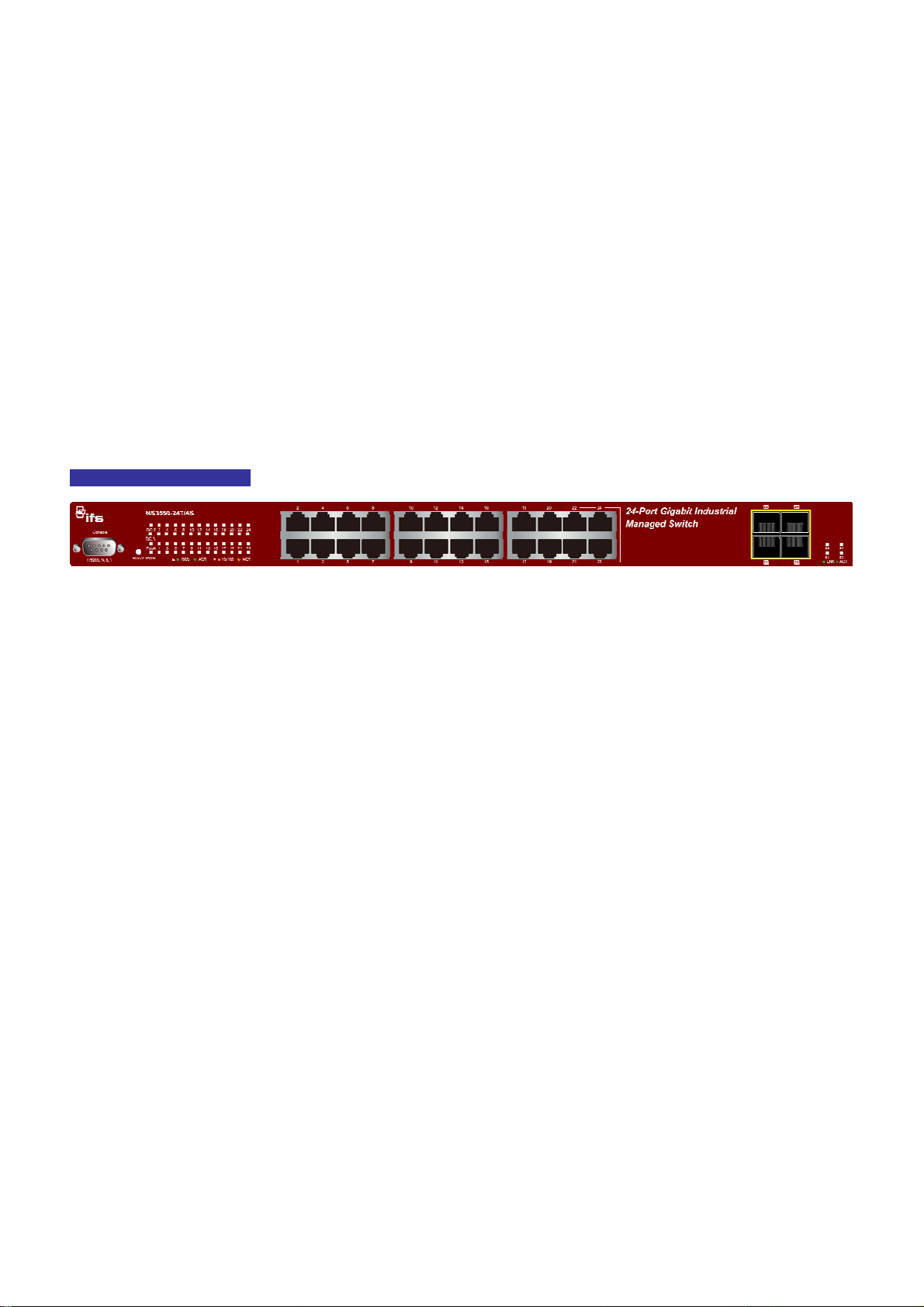
INSTALLATION
This section describes the hardware features and installation of the Managed Switch on the desktop or rack mount. For easier
management and control of the Managed Switch, familiarize yourself with its display indicators, and ports. Front panel
illustrations in this chapter display the unit LED indicators. Before connecting any network device to the Managed Switch, please
read this chapter completely.
Hardware Description
Switch Front Panel
The unit front panel provides a simple interface monitoring the Switch. Figure 2-1 shows the front panel of the Managed Switch.
NS3550-24T/4S Front Panel
Figure 2-1 NS3550-24T/4S Front Panel
■ Gigabit TP interface
10/100/1000Base-T Copper, RJ-45 Twist-Pair: Up to 100 meters.
■ Gigabit SFP slots
1000Base-SX/LX mini-GBIC slot, SFP (Small Factor Pluggable) transceiver module: From 550 meters (Multi-mode fiber), up
to 10/30/50/70 kilometers (Single-mode fiber).
■ Console Port
The console port is a DB9, RS-232 male serial port connector. It is an interface for connecting a terminal directly. Through the
console port, it provides rich diagnostic information includes IP Address setting, factory reset, port management, link status
and system setting. Users can use the attached RS-232 cable in the package and connect to the console port on the device.
After the connection, users can run any terminal emulation program (Hyper Terminal, ProComm Plus, Telix, Winterm, etc. to
enter the startup screen of the device.
■ Reset button
On the left side of front panel, the reset button is designed for rebooting the Managed Switch without a power cycle. The
following is the summary table of Reset button functions:
26
Page 27
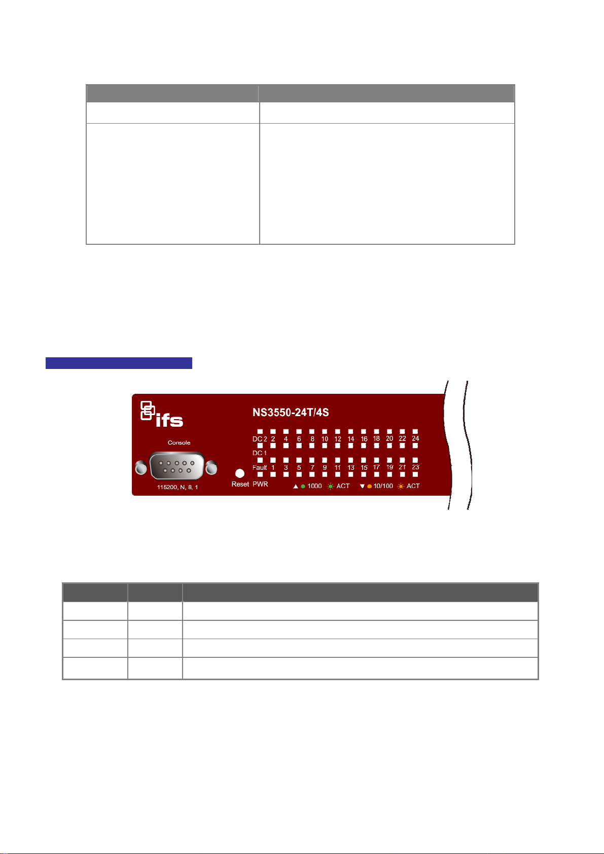
NS3550-24T/4S User Manual
Reset Button Pressed and Released Function
< 5 sec: System reboot Reboot the Managed Switch
Reset the Managed Switch to Factory Default configuration.
The Managed Switch will then reboot and load the default
settings as below:
> 5 sec: Factory Default
。 Default Username: admin
。 Default Password: admin
。 Default IP address: 192.168.0.100
。 Subnet mask: 255.255.255.0
。 Default Gateway: 192.168.0.254
LED Indications
The front panel LEDs indicates instant status of port links, data activity and system power; helps monitor and troubleshoot when
needed. Figure 2-2 shows the LED indications of these Managed Switch.
NS3550-24T/4S LED indication
■ System
LED Color Function
DC1 Green
DC2 Green Illuminates to indicate that the Switch is powered on by DC2 input.
Illuminates to indicate that the Switch is powered on by DC1 input.
Figure 2-2 NS3550-24T/4S LED Panel
Fault Green Illuminates to indicate that Switch AC/DC or port has failed.
PWR Green
Illuminates to indicate that the Switch is powered on.
Blink to indicate the System is running under booting procedure.
27
Page 28
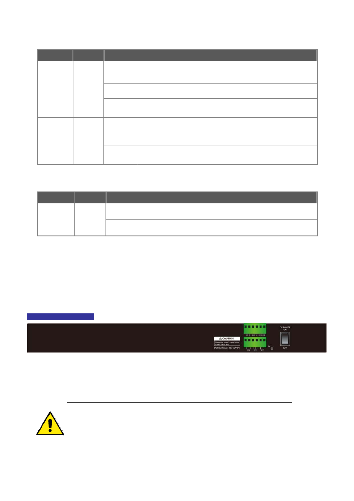
■ 10/100/1000Base-T interfaces
LED Color Function
Iluminates:
To indicate the link through that port is successfully established with speed
1000Mbps.
1000
Green
LNK/ACT
10/100
Orange
LNK/ACT
■ 1000Base-SX/LX SFP interfaces (Shared Port-21~Port-24)
LED Color Function
LNK/ACT Green
Blink:
Off:
Illuminates:
Blink:
Off:
Lights:
Off:
To indicate the link through that SFP port is successfully established.
To indicate that the SFP port is link down
To indicate that the switch is actively sending or receiving data over that port.
If L10/100 NK/ACT LED light-> indicates that the port is operating at 10Mbps
or 100Mbps.
If LNK/ACT LED Off -> indicate that the port is link down.
To indicate the link through that port is successfully established with speed
10Mbps or 100Mbps.
To indicate that the switch is actively sending or receiving data over that port.
If 1000 LNK/ACT LED light-> indicates that the port is operating at
1000Mbps
If 1000 LNK/ACT LED Off -> indicates that the port is link down.
Switch Rear Panel
The rear panel of the Managed Switch indicates an AC inlet power socket, which works with an input power range from 50-60Hz.
Figure 2-3 shows the rear panel of this Managed Switch.
NS3550-24T/4S Rear Panel
Figure 2-3 Rear Panel of the NS3550-24T/4S
1. The device requires a power connection to operate. If your networks should active all the
time, please consider using UPS (Uninterrupted Power Supply) for your device. It will
prevent you from network data loss or network downtime.
2. For additional protection against unregulated voltage or current surges, you may also
want to consider surge suppression as part of your installation.
28
Page 29
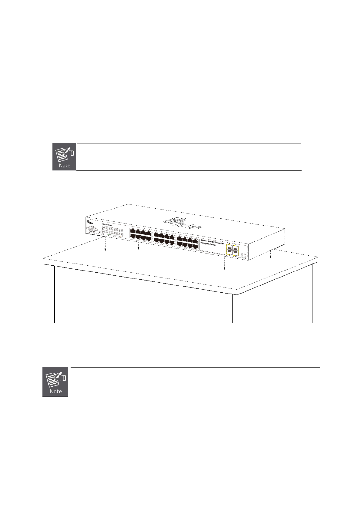
NS3550-24T/4S User Manual
Install the Switch
This section describes how to install your Managed Switch and make connections to the Managed Switch. Please read the
following topics and perform the procedures in the order being presented. To install your Managed Switch on a desktop or shelf,
simply complete the following steps.
Desktop Installation
To install the Managed Switch on desktop or shelf, please follows these steps:
As desktop and rackmount installation demonstration as following is an example for a
GE-DSSG-244-POE, however, the installation procedure of NS3550-24T/4S is the same with
a GE-DSSG-244-POE.
Step1: Attach the rubber feet to the recessed areas on the bottom of the Managed Switch.
Step2: Place the Managed Switch on the desktop or the shelf near an AC power source, as shown in Figure 2-4.
Figure 2-4 Place the Managed Switch on the Desktop
Step3: Keep enough ventilation space between the Managed Switch and the surrounding objects.
When choosing a location, please keep in mind the environmental restrictions discussed in Chapter 1,
Section 4, Product Specification.
Step4: Connect the Managed Switch to network devices.
Connect one end of a standard network cable to the 10/100/1000 RJ-45 ports on the front of the Managed Switch
Connect the other end of the cable to the network devices such as printer servers, workstations or routers…etc.
29
Page 30
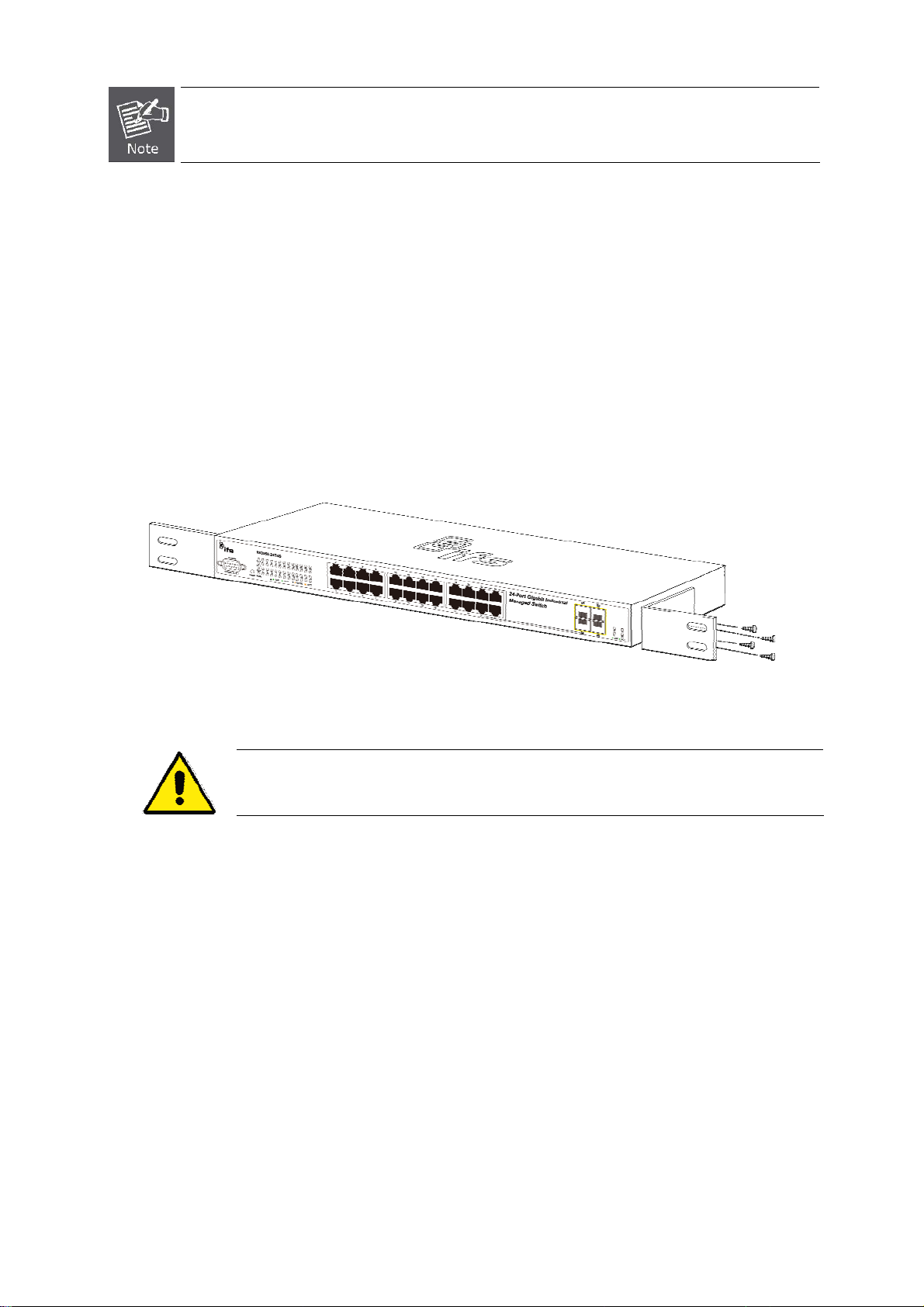
Connection to the Managed Switch requires UTP Category 5 network cabling with RJ-45 tips. For more
information, please see the Cabling Specification in Appendix A.
Step5: Supply power to the Managed Switch.
Connect one end of the power cable to the Managed Switch.
Connect the power plug of the power cable to a standard wall outlet.
When the Managed Switch receives power, the Power LED should remain solid Green.
Rack Mounting
To install the Managed Switch in a 19-inch standard rack, please follow the instructions described below.
Step1: Place the Managed Switch on a hard flat surface, with the front panel positioned towards the front side.
Step2: Attach the rack-mount bracket to each side of the Managed Switch with supplied screws attached to the package.
Figure 2-5 shows how to attach brackets to one side of the Managed Switch.
Figure 2-5 Attach Brackets to the Managed Switch.
You must use the screws supplied with the mounting brackets. Damage caused to the parts by
using incorrect screws would invalidate the warranty.
Step3: Secure the brackets tightly.
Step4: Follow the same steps to attach the second bracket to the opposite side.
Step5: After the brackets are attached to the Managed Switch, use suitable screws to securely attach the brackets to the rack, as
shown in Figure 2-6.
30
Page 31

NS3550-24T/4S User Manual
Figure 2-6 Mounting the Managed Switch on a Rack
Step6: Proceeds with the steps 4 and steps 5 of session 2.2.1 Desktop Installation to connect the network cabling and supply
power to the Managed Switch.
Installing the SFP transceiver
The sections describe how to plug-in an SFP transceiver into an SFP slot.
The SFP transceivers are hot-swappable. You can plug-in and out the transceiver to/from any SFP port without a need to shut the
power down. SFPs and fiber cables are plugged in as shown in Figure 2-7.
Figure 2-7 Plug-in the SFP Transceiver
31
Page 32

Approved IFS SFP Transceivers
IFS Managed Switch supports both Single mode and Multi-mode SFP transceiver. Please refer to below chart, as well as the IFS
website for the latest compatible SFP modules:
We recommend using IFS SFPs on the Managed Switch. If you insert a SFP transceiver that is not
supported, the Managed Switch will not recognize it.
Before connect the other Managed Switches, workstation or Media Converter.
1. Make sure both sides use the same type of SFP transceiver, for example: 1000Base-SX to 1000Base-SX, 1000Base-LX to
1000Base-LX.
2. Check the fiber-optic cable type match the SFP transceiver model.
To connect to 1000Base-SX SFP transceiver, use the Multi-mode fiber cable- with one side must be male duplex LC
connector type.
To connect to 1000Base-LX SFP transceiver, use the Single-mode fiber cable-with one side must be male duplex LC
connector type.
32
Page 33

NS3550-24T/4S User Manual
Connect the fiber cable
1. Attach the duplex LC connector on the network cable into the SFP transceiver.
2. Connect the other end of the cable to a device – switches with SFP installed, fiber NIC on a workstation or a Media
Converter.
3. Check the LNK/ACT LED of the SFP slot on the front of the Managed Switch. Ensure that the SFP transceiver is operating
correctly.
4. Check the Link mode of the SFP port if the link failed.
Remove the transceiver module
1. Make sure there is no network activity. Go through the management interface of the switch to disable the port in advance.
2. Remove the Fiber Optic Cable gently.
3. Turn the handle of the MGB module to the horizontal position.
4. Pull out the module gently with the handle.
Figure 2-8 Pull out the SFP Transceiver
Never pull out the module without pull the handle or the push bolts on the module. Directly
pulling out the module may damage the module and SFP module slot of the Managed Switch.
MFB series SFP module remove procedure is the same with MGB series SFP Module.
33
Page 34

Wiring the Power Input
The 6-contact terminal block connector on the rear panel of NS3550-24T/4S is used for two DC redundant powers inputs. Please
follow the steps below to insert the power wire.
1. Insert positive / negative DC power wires into the contacts 1 and 2 for DC POWER 1, or 5 and 6 for DC POWER 2.
Figure 2-9 Wiring the Redundant Power Inputs
2. Tighten the wire-clamp screws to prevent the wires from loosening.
1 2 3 4 5 6
DC 2 DC 1
+ - + -
Figure 2-10 6-Pin Terminal Block Power Wiring Input
The wire gauge for the terminal block should be in the range between 12 ~ 24 AWG.
34
Page 35

NS3550-24T/4S User Manual
Wiring the Digital Input / Output
The 6-contact terminal block connector on the rear panel of the NS3550-24T/4S is used for Digital Input and Digital Output.
Please follow the steps below to insert wire.
1. The NS3550-24T/4S offers two DI and DO groups. 1 and 2 are DI groups, 3 and 4 are DO groups and 5 is GND
(ground).The 6 pin is unassigned.
Figure 2-11 Wiring the Redundant Power Inputs
2. Tighten the wire-clamp screws for preventing the wires from loosing.
1 2 3 4 5 6
DI0 DI1 DO0 DO1 GND GND
Figure 2-12 6-Pin Terminal Block DI / DO Wiring Input
3. There are two Digital Input groups for you to monitor two different devices. The following topology shows how to wire DI0
and DI1.
The required voltage of 2 digital input groups is -30V DC maximum, current is 8mA maximum.
The required voltage of 2 digital output groups is -30V DC maximum, current is 200mA maximum.
35
Page 36

Figure 2-13 Wires DI0 and DI1 to Open Detector
4. There are two Digital Output groups for you to be notified of if the NS3550-24T/4S port fails or power fails and issues a high
or low signal to external device. The following topology shows how to wire DO0 and DO1.
Figure 2-14 Wiring DO0 and DO1 to Open Detector
36
Page 37

NS3550-24T/4S User Manual
37
Page 38

SWITCH MANAGEMENT
This chapter explains the methods that you can use to configure management access to the Managed Switch. It describes the
types of management applications and the communication and management protocols that deliver data between your
management device (workstation or personal computer) and the system. It also contains information about port connection
options.
This chapter covers the following topics:
Requirements
Management Access Overview
Administration Console Access
Web Management Access
SNMP Access
Standards, Protocols, and Related Reading
Requirements
Workstations of subscribers running Windows 98/ME, NT4.0, 2000/XP, 2003, Vistsa, MAC OS9 or later, Linux,
UNIX or other platform compatible with TCP/IP protocols.
Workstation installed with Ethernet NIC (Network Interface Card)
Serial Port connection (Terminal)
Above PC with COM Port (DB9 / RS-232) or USB-to-RS-232 converter
Ethernet Port connection
Network cables - Use standard network (UTP) cables with RJ45 connectors.
Above Workstation installed with WEB Browser and JAVA runtime environment Plug-in
It is recommended to use Internet Explore 7.0 or above to access Managed Switch.
38
Page 39

NS3550-24T/4S User Manual
Management Access Overview
The Managed Switch gives you the flexibility to access and manage it using any or all of the following methods:
An administration console
Web browser interface
An external SNMP-based network management application
The administration console and Web browser interface support are embedded in the Managed Switch software and are available
for immediate use. Each of these management methods has their own advantages. Table 3-1 compares the three management
methods.
Method Advantages Disadvantages
Console
Web Browser
SNMP Agent
No IP address or subnet needed
Text-based
Telnet functionality and HyperTerminal
built into Windows
95/98/NT/2000/ME/XP operating
systems
Secure
Ideal for configuring the switch remotely
Compatible with all popular browsers
Can be accessed from any location
User friendly GUI
Communicates with switch functions at
the MIB level
Based on open standards
Table 3-1 Management Methods Comparison
Must be near switch or use dial-up connection
Not convenient for remote users
Modem connection may prove to be unreliable
or slow
Security can be compromised (hackers need
only know the IP address and subnet mask)
May encounter lag times on poor connections
Requires SNMP manager software
Least visually appealing of all three methods
Some settings require calculations
Security can be compromised (hackers need
only know the community name)
Administration Console
The administration console is an internal, character-oriented, and command line user interface for performing system
administration such as displaying statistics or changing option settings. Using this method, you can view the administration
console from a terminal, personal computer, Apple Macintosh, or workstation connected to the switch's console (serial) port.
There are two ways to use this management method: via direct access or modem port access. The following sections describe
these methods. For more information about using the console, refer to Chapter 5 Command Line Interface Console
Management.
39
Page 40

Figure 3-1 Console Management Diagram
Direct Access
Direct access to the administration console is achieved by directly connecting a terminal or a PC equipped with a
terminal-emulation program (such as HyperTerminal) to the Managed Switch console (serial) port.
When using this management method, a straight DB9 RS-232 cable is required to connect the switch to the PC. After making
this connection, configure the terminal-emulation program to use the following parameters:
The default parameters are:
115200 bps
8 data bits
No parity
1 stop bit
Figure 3-2 Terminal Parameter Settings
You can change these settings, if desired, after you log on. This management method is often preferred because you can remain
connected and monitor the system during system reboots. Also, certain error messages are sent to the serial port, regardless of
40
Page 41

NS3550-24T/4S User Manual
the interface through which the associated action was initiated. A Macintosh or PC attachment can use any terminal-emulation
program for connecting to the terminal serial port. A workstation attachment under UNIX can use an emulator such as TIP.
Web Management
The Managed Switch offers management features that allow users to manage the Managed Switch from anywhere on the
network through a standard browser such as Microsoft Internet Explorer. After you set up your IP address for the switch, you can
access the Managed Switch's Web interface applications directly in your Web browser by entering the IP address of the Managed
Switch.
Figure 3-3 Web Management Diagram
You can then use your Web browser to list and manage the Managed Switch configuration parameters from one central location,
just as if you were directly connected to the Managed Switch's console port. Web Management requires either Microsoft
Internet Explorer 6.0 or later, Safari or Mozilla Firefox 1.5 or later.
Figure 3-4 Web Main Screen of Managed Switch
41
Page 42

SNMP-Based Network Management
You can use an external SNMP-based application to configure and manage the Managed Switch, such as SNMPc Network
Manager, HP Openview Network Node Management (NNM) or What’s Up Gold. This management method requires the SNMP
agent on the switch and the SNMP Network Management Station to use the same community string. This management method,
in fact, uses two community strings: the get community string and the set community string. If the SNMP Net-work
management Station only knows the set community string, it can read and write to the MIBs. However, if it only knows the get
community string, it can only read MIBs. The default gets and sets community strings for the Managed Switch are public.
Figure 3-5 SNMP Management Diagram
42
Page 43

NS3550-24T/4S User Manual
WEB CONFIGURATION
This section introduces the configuration and functions of the Web-Based management.
About Web-based Management
The Managed Switch offers management features that allow users to manage the Managed Switch from anywhere on the
network through a standard browser such as Microsoft Internet Explorer.
The Web-Based Management supports Internet Explorer 7.0. It is based on Java Applets with an aim to reduce network
bandwidth consumption, enhance access speed and present an easy viewing screen.
By default, IE7.0 or later version does not allow Java Applets to open sockets. The user has to
explicitly modify the browser setting to enable Java Applets to use network ports.
The Managed Switch can be configured through an Ethernet connection, make sure the manager PC must be set on same the IP
subnet address with the Managed Switch.
For example, the default IP address of the Managed Switch is 192.168.0.100, then the manager PC should be set at 192.168.0.x
(where x is a number between 1 and 254, except 100), and the default subnet mask is 255.255.255.0.
If you have changed the default IP address of the Managed Switch to 192.168.1.1 with subnet mask 255.255.255.0 via console,
then the manager PC should be set at 192.168.1.x (where x is a number between 2 and 254) to do the relative configuration on
manager PC.
Figure 4-1-1 Web Management Diagram
43
Page 44

Logging on the switch
1. Use Internet Explorer 7.0 or above Web browser. Enter the factory-default IP address to access the Web interface. The
factory-default IP Address as following:
http://192.168.0.100
2. When the following login screen appears, please enter the default username "admin" with password “admin” (or the
username/password you have changed via console) to login the main screen of Managed Switch. The login screen is
shown in Figure 4-1-2.
Figure 4-1-2 Login Screen
Default User name: admin
Default Password: admin
After entering the username and password, the main screen is shown in Figure 4-1-3.
44
Page 45

NS3550-24T/4S User Manual
Figure 4-1-3 Default Main Page
Now, you can use the Web management interface to continue the switch management or manage the Managed Switch by Web
interface. The Switch Menu on the left of the web page let you access all the commands and statistics the Managed Switch
provides.
1. It is recommended to use Internet Explore 7.0 or above to access Managed Switch.
2. Since the changed IP address take effect immediately after you click on the Save button, you
need to use the new IP address to access the Web interface.
3. For security reason, please change and memorize the new password after this first setup.
4. The Switch only accepts command in lowercase letters in the web interface.
45
Page 46

Main Web Page
The Managed Switch provides a Web-based browser interface for configuring and managing it. This interface allows you to
access the Managed Switch using the Web browser of your choice. This chapter describes how to use the Managed Switch’s
Web browser interface to configure and manage it.
Main Functions Menu
Copper Port Link Status
SFP Port Link Status
Main Screen
Figure 4-1-4 Main Page
Panel Display
The web agent displays an image of the Managed Switch’s ports. The Mode can be set to display different information for the
ports, including Link up or Link down. Clicking on the image of a port opens the Port Statistics page.
The port states are illustrated as follows:
Help Button
State Disabled Down Link
RJ-45 Ports
SFP Ports
46
Page 47

NS3550-24T/4S User Manual
Main Menu
Using the onboard web agent, you can define system parameters, manage and control the Managed Switch, and all its ports, or
monitor network conditions. Via the Web-Management, the administrator can setup the Managed Switch by select the functions
those listed in the Main Function. The screen is shown in Figure 4-1-5.
Figure 4-1-5 NS3550-24T/4S Managed Switch Main Functions Menu
47
Page 48

System
Use the System menu items to display and configure basic administrative details of the Managed Switch. Under System the
following topics are provided to configure and view the system information: This section has the following items:
■ System Information The switch system information is provided here.
■ IP Configuration Configure the switch-managed IP information on this page.
■ IPv6 Configuration Configure the switch-managed IPv6 information on this page.
■ Users Configuration
■ Users Privilege Levels
■ NTP Configuration Configure NTP on this page.
■ UPnP Configure UPnP on this page.
■ DHCP Relay Configure DHCP Relay on this page.
■ DHCP Relay Statistics This page provides statistics for DHCP relay.
■ CPU Load This page displays the CPU load, using a SVG graph.
■ System Log The switch system log information is provided here.
■ Detailed Log The switch system detailed log information is provided here.
■ Remote S yslog Configure remote syslog on this page.
This page provides an overview of the current users. Currently the only way
to login as another user on the web server is to close and reopen the browser.
This page provides an overview of the privilege levels.
■ Web Firmware Upgrade This page facilitates an update of the firmware controlling the switch.
■ TFTP Firmware Upgrade Upgrade the firmware via TFTP server
■ Configuration Backup
■ Configuration Upload
■ SMTP Configure Configure SMTP for alarm on this page.
■ Digital input/output This page is for you setting up digital input and digital output and what kind of
■ Fault Alarm This page is for you monitoring power and port status. If they are failed,
■ Factory Default
■ Sys
tem Reboot You can restart the switch on this page. After restart, the switch will boot
You can save the switch configuration. The configuration file is in XML format
with a hierarchy of tags.
You can load the switch configuration. The configuration file is in XML format
with a hierarchy of tags.
action will be done.
system will trigger alarm.
You can reset the configuration of the switch on this page. Only the IP
configuration is retained.
normally.
48
Page 49

NS3550-24T/4S User Manual
System Information
The System Info page provides information for the current device information. System Info page helps a switch administrator to
identify the hardware MAC address, software version and system uptime. The screen is shown in Figure 4-2-1.
The page includes the following fields:
Object Description
Contact
Name
Location
MAC A ddr es s
Power Status
Temperature
System Date
Figure 4-2-1 System Information Page Screenshot
The system contact configured in Configuration | System | Information | System
Contact.
The system name configured in Configuration | System | Information | System
Name.
The system location configured in Configuration | System | Information | System
Location.
The MAC Address of this switch.
Indicate DC power supply input of this switch.
Indicate main chipset temperature.
The current (GMT) system time and date. The system time is obtained through the
configured SNTP Server, if any.
49
Page 50

System Uptime
The period of time the device has been operational.
Software Version
Software Date
Buttons
Auto-refresh : Check this box to enable an automatic refresh of the page at regular intervals.
: Click to refresh the page; any changes made locally will be undone.
The software version of the switch.
The software version date of the switch.
IP Configuration
The IP Configuration includes the IP Address, Subnet Mask and Gateway. The Configured column is used to view or change the
IP configuration. Fill up the IP Address, Subnet Mask and Gateway for the device. The screen is shown in Figure 4-2-2.
Figure 4-2-2 IP Configuration Page Screenshot
The Current column is used to show the active IP configuration.
Object Description
DHCP Client
IP Address
IP Mask
Enable the DHCP client by checking this box. If DHCP fails and the configured IP
address is zero, DHCP will retry. If DHCP fails and the configured IP address is
non-zero, DHCP will stop and the configured IP settings will be used. The DHCP
client will announce the configured System Name as hostname to provide DNS
lookup.
Provide the IP address of this switch in dotted decimal notation.
Provide the IP mask of this switch dotted decimal notation.
50
Page 51

NS3550-24T/4S User Manual
Buttons
IP Router
VLAN ID
DNS Server
DNS Proxy
: Click to save changes.
: Click to undo any changes made locally and revert to previously saved values.
: Click to undo any changes made locally and revert to previously saved values.
Provide the IP address of the router in dotted decimal notation.
Provide the managed VLAN ID. The allowed range is 1 through 4095.
Provide the IP address of the DNS Server in dotted decimal notation.
When DNS proxy is enabled, DUT will relay DNS requests to the current
configured DNS server on DUT, and reply as a DNS resolver to the client device
on the network.
IPv6 Configuration
Configure the switch-managed IPv6 information on this page.
The Configured column is used to view or change the IPv6 configuration. The Current column is used to show the active IPv6
configuration. The screen is shown in Figure 4-2-3.
Figure 4-2-3 IPv6 Configuration Page Screenshot
The page includes the following fields:
Object Description
Auto Configuration
Address
Enable IPv6 auto-configuration by checking this box. If fails, the configured IPv6
address is zero. The router may delay responding to a router solicitation for a few
seconds, the total time needed to complete auto-configuration can be significantly
longer.
Provide the IPv6 address of this switch. IPv6 address is in 128-bit records
represented as eight fields of up to four hexadecimal digits with a colon separate
each field (:). For example, 'fe80::215:c5ff:fe03:4dc7'. The symbol '::' is a special
syntax that can be used as a shorthand way of representing multiple 16-bit groups
of contiguous zeros; but it can only appear once. It also used a following legally
51
Page 52

IPv4 address. For example, '::192.1.2.34'.
Buttons
Prefix
Router
VLAN ID
: Click to save changes.
: Click to undo any changes made locally and revert to previously saved values.
Provide the IPv6 Prefix of this switch. The allowed range is 1 through 128.
Provide the IPv6 gateway address of this switch. IPv6 address is in 128-bit
records represented as eight fields of up to four hexadecimal digits with a colon
separate each field (:). For example, 'fe80::215:c5ff:fe03:4dc7'. The symbol '::' is a
special syntax that can be used as a shorthand way of representing multiple 16-bit
groups of contiguous zeros; but it can only appear once. It also used a following
legally IPv4 address. For example, '::192.1.2.34'.
Provide the IPv6 SNTP Server address of this switch. IPv6 address is in 128-bit
records represented as eight fields of up to four hexadecimal digits with a colon
separate each field (:). For example, 'fe80::215:c5ff:fe03:4dc7'. The symbol '::' is a
special syntax that can be used as a shorthand way of representing multiple 16-bit
groups of contiguous zeros; but it can only appear once. It also used a following
legally IPv4 address. For example, '::192.1.2.34'.
Provide the managed VLAN ID. The allowed range is 1 through 4095
Users Configuration
It is allowed to configure the Managed Switch to authenticate users logging into the system for management access using local
authentication methods, such as telnet and Web browser. The latest UTC Managed Switch provides totally six different security
levels in 3 groups for local user management.
Group Access / Security Level Access
Master Admin Master
Master Viewer
IT Admin IT
IT Viewer
Security Admin Security
Security Viewer
This web page provide user configuration for switch management access level, the web screen is shown in Figure 4-2-4 appears.
Refer to Appendix B
52
Page 53

Figure 4-2-4: User Configuration Interface Screenshot
The page includes the following fields:
Object Description
NS3550-24T/4S User Manual
Username: Display Username of the Managed Switch.
Access Level: Display the access level of the Managed Switch.
Edit: Provide edit current specific user setting.
Provide add new user setting of the Managed Switch, the web screen is shown in
Add New User:
Figure 4-2-5 appears.
53
Page 54

Add / Edit User
This page configures a user – add, edit or delete user.
Figure 4-2-5: Add New User Configuration Interface Screenshot
The page includes the following fields:
Object Description
User Name:
Access Level:
Assign/Change Password:
Reconfirm Password:
Apply:
Delete User
Assign Username for the Managed Switch.
Assign the access level of the Managed Switch; the available options are:
Master Admin
Master Viewer
IT Admin
IT Viewer
Security Admin
Security Viewer
Assign password for the Managed Switch.
Input password again to confirm setting.
Press this button to take affect.
Delete the current user. This button is not available for new configurations (Add
new user)
Once the new user is added, the new user entry shown in the Users Configuration page.
54
Page 55

NS3550-24T/4S User Manual
Figure 4-2-6 User Configuration page screenshot
After change the default password, if you forget the password. Please press the “Reset” button
in the front panel of the Managed Switch over 10 seconds and then release, the current setting
includes VLAN, will be lost and the Managed Switch will restore to the default mode.
The preset user priorities for each function is listed under the section titled Appendix B.
55
Page 56

Users Privilege Levels
This page provides an overview of the privilege levels. After setup completed, please press “Save” button to take effect. Please
login web interface with new user name and password, The screen is shown in Figure 4-2-7.
Figure 4-2-7 Privilege Levels Configuration Page Screenshot t
The page includes the following fields:
Object Description
Group Name
The name identifying the privilege group. In most cases, a privilege level group
consists of a single module (e.g. LACP, RSTP or QoS), but a few of them contains
more than one. The following description defines these privilege level groups in
56
Page 57

Buttons
details:
System: Contact, Name, Location, Timezone, Log.
Security: Authentication, System Access Management, Port (contains Dot1x port,
MAC based and the MAC Address Limit), ACL, HTTPS, SSH, ARP Inspection and
IP source guard.
IP: Everything except 'ping'.
Port: Everything except 'VeriPHY'.
Diagnostics: 'ping' and 'VeriPHY'.
Maintenance: CLI- System Reboot, System Restore Default, System Password,
Configuration Save, Configuration Load and Firmware Load. Web- Users,
Privilege Levels and everything in Maintenance.
Debug: Only present in CLI.
Privilege Level
: Click to save changes.
: Click to undo any changes made locally and revert to previously saved values.
Every privilege level group has an authorization level for the following sub groups:
configuration read-only, configuration/execute read-write, status/statistics
read-only, and status/statistics read-write (e.g. for clearing of statistics).
NS3550-24T/4S User Manual
57
Page 58

NTP Configuration
Configure NTP on this page.
NTP is an acronym for Network Time Protocol, a network protocol for synchronizing the clocks of computer systems. NTP uses
UDP (data grams) as transport layer. You can specify NTP Servers and set GMT Time zone. The NTP Configuration screen is
shown in Figure 4-2-8.
The page includes the following fields:
Object Description
Mode
Timezone
Server #
Buttons
Figure 4-2-8 NTP Configuration Page Screenshot
Indicates the NTP mode operation. Possible modes are:
Enabled: Enable NTP mode operation. When enable NTP mode operation, the
agent forward and to transfer NTP messages between the clients and the server
when they are not on the same subnet domain.
Disabled: Disable NTP mode operation.
Allow select the time zone according to current location of switch.
Provide the NTP IPv4 or IPv6 address of this switch. IPv6 address is in 128-bit
records represented as eight fields of up to four hexadecimal digits with a colon
separates each field (:). For example, 'fe80::215:c5ff:fe03:4dc7'. The symbol '::' is
a special syntax that can be used as a shorthand way of representing multiple
16-bit groups of contiguous zeros; but it can only appear once. It also used a
following legally IPv4 address. For example, '::192.1.2.34'.
: Click to save changes.
: Click to undo any changes made locally and revert to previously saved values.
UPnP Configuration
Configure UPnP on this page.
58
Page 59

NS3550-24T/4S User Manual
UPnP is an acronym for Universal Plug and Play. The goals of UPnP are to allow devices to connect seamlessly and to simplify
the implementation of networks in the home (data sharing, communications, and entertainment) and in corporate environments
for simplified installation of computer components. The UPnP Configuration screen is shown in Figure 4-2-9.
The page includes the following fields:
Object Description
Mode
TTL
Advertising Duration
Figure 4-2-9 UPnP
Indicates the UPnP operation mode. Possible modes are:
Enabled: Enable UPnP mode operation.
Disabled: Disable UPnP mode operation.
When the mode is enabled, two ACEs are added automatically to trap UPNP
related packets to CPU. The ACEs are automatically removed when the mode is
disabled.
The TTL value is used by UPnP to send SSDP advertisement messages. Valid
values are in the range 1 to 255.
The duration, carried in SSDP packets, is used to inform a control point or control
points how often it or they should receive a SSDP advertisement message from
this switch. If a control point does not receive any message within the duration, it
will think that the switch no longer exists. Due to the unreliable nature of UDP, in
the standard it is recommended that such refreshing of advertisements to be done
at less than one-half of the advertising duration. In the implementation, the switch
sends SSDP messages periodically at the interval one-half of the advertising
duration minus 30 seconds. Valid values are in the range 100 to 86400.
Configuration Page Screenshot
59
Page 60

Buttons
: Click to save changes.
: Click to undo any changes made locally and revert to previously saved values.
Figure 4-2-10 UPnP
devices shows on Windows My Network Places
DHCP Relay
Configure DHCP Relay on this page. DHCP Relay is used to forward and to transfer DHCP messages between the clients and
the server when they are not on the same subnet domain.
The DHCP option 82 enables a DHCP relay agent to insert specific information into DHCP request packet when forwarding
client DHCP packets to a DHCP server and remove the specific information from a DHCP reply packets when forwarding server
DHCP packets to a DHCP client. The DHCP server can use this information to implement IP address or other assignment policies.
Specifically the option works by setting two sub-options:
Circuit ID (option 1)
Remote ID (option2).
The Circuit ID sub-option is supposed to include information specific to which circuit the request came in on.
The Remote ID sub-option was designed to carry information relating to the remote host end of the circuit.
60
Page 61

NS3550-24T/4S User Manual
The definition of Circuit ID in the switch is 4 bytes in length and the format is "vlan_id" "module_id" "port_no". The parameter of
"vlan_id" is the first two bytes represent the VLAN ID. The parameter of "module_id" is the third byte for the module ID. The
parameter of "port_no" is the fourth byte and it means the port number.
The Remote ID is 6 bytes in length, and the value is equal the DHCP relay agent’s MAC address. The DHCP Relay Configuration
screen is shown in Figure 4-2-11.
Figure 4-2-11 DHCP Relay
Configuration Page Screenshot
The page includes the following fields:
Object Description
Relay Mode
Relay Server
Relay Information
Mode
Relay Information
Policy
Indicates the DHCP relay mode operation. Possible modes are:
Enabled: Enable DHCP relay mode operation. When enable DHCP relay mode
operation, the agent forward and to transfer DHCP messages between the clients
and the server when they are not on the same subnet domain. And the DHCP
broadcast message won't flood for security considered.
Disabled: Disable DHCP relay mode operation.
Indicates the DHCP relay server IP address. A DHCP relay agent is used to
forward and to transfer DHCP messages between the clients and the server when
they are not on the same subnet domain.
Indicates the DHCP relay information mode option operation. Possible modes
are:
Enabled: Enable DHCP relay information mode operation. When enable DHCP
relay information mode operation, the agent insert specific information (option
82) into a DHCP message when forwarding to DHCP server and remove it from a
DHCP message when transferring to DHCP client. It only works under DHCP
relay operation mode enabled.
Disabled: Disable DHCP relay information mode operation.
Indicates the DHCP relay information option policy. When enable DHCP relay
information mode operation, if agent receives a DHCP message that already
contains relay agent information. It will enforce the policy. And it only works under
DHCP relay information operation mode enabled. Possible policies are:
Replace: Replace the original relay information when receive a DHCP message
that already contains it.
Keep: Keep the original relay information when receive a DHCP message that
already contains it.
Drop: Drop the package when receive a DHCP message that already contains
relay information.
Buttons
: Click to save changes.
: Click to undo any changes made locally and revert to previously saved values.
61
Page 62

DHCP Relay Statistics
This page provides statistics for DHCP relay. The DHCP Relay Statistics screen is shown in Figure 4-2-12.
Figure 4-2-12 DHCP Relay Statistics Page Screenshot
The page includes the following fields:
Server Statistics
Object Description
Transmit to Server
The packets number that relayed from client to server.
Transmit Error
Receive form Server
Receive Missing Agent
Option
Receive Missing
Circuit ID
Receive Missing
Remote ID
Receive Bad Circuit ID
Receive Bad Remote
ID
Client Statistics
Object Description
Transmit to Client
Transmit Error
Receive form Client
The packets number that packet of error sent packets to client.
The packets number that received packets from server.
The packets number that received packets without agent information options.
The packets number that received packets which the Circuit ID option was
missing.
The packets number that received packets which Remote ID option was missing.
The packets number that the Circuit ID option did not match known the circuit ID.
The packets number that the Remote ID option did not match the known Remote
ID.
The number of packets relayed packets from server to client.
The number of packets that sent error packets to servers.
The number of packets received from the server.
Receive Agent Option
Replace Agent Option
Keep Agent Optin
The number of packets received with relay agent information option.
The number of packets that replaced received packets with relay agent
information option.
The number of packets that keepped received packets with relay agent
information option.
62
Page 63

NS3550-24T/4S User Manual
Drop Agent Option
Buttons
Auto-refresh : Check this box to enable an automatic refresh of the page at regular intervals.
: Click to refresh the page; any changes made locally will be undone.
: Clear all statistics.
The number packets that dropped received packets with relay agent information
option.
63
Page 64

CPU Load
This page displays the CPU load, using a SVG graph.
The load is measured as averaged over the last 100ms, 1sec and 10 seconds intervals. The last 120 samles are graphed, and
the last numbers are displayed as text as well.
In order to display the SVG graph, your browser must support the SVG format. Consult the SVG Wiki for more information on
browser support. Specifically, at the time of writing, Microsoft Internet Explorer will need to have a plugin installed to support SVG.
The CPU Load screen is shown in Figure 4-2-13.
Buttons
Auto-refresh
Figure 4-2-13 CPU Load Page Screenshot
: Check this box to enable an automatic refresh of the page at regular intervals.
If your browser can not display this chart, please download Adobe SVG tool and install it in your
computer.
64
Page 65

NS3550-24T/4S User Manual
System Log
The switch system log information is provided here. The System Log screen is shown in Figure 4-2-14.
Figure 4-2-14 System Log Page Screenshot
The page includes the following fields:
Object Description
ID
Level
Time
Message
Buttons
Auto-refresh : Check this box to enable an automatic refresh of the page at regular intervals.
: Click to refresh the page; any changes made locally will be undone.
: Clear all statistics.
The ID (>= 1) of the system logging entry.
The level of system logging entry. The following level types are supported:
Info: Information level of the system log.
Warning: Warning level of the system log.
Error: Error level of the system log.
All: All levels.
The time of the system log entry.
The message of the system logging entry.
: Hide the statistics.
: Download the statistics.
: Updates the system log entries, starting from the first available entry ID.
: Updates the system log entries, ending at the last entry currently displayed.
: Updates the system log entries, starting from the last entry currently displayed.
65
Page 66

: Updates the system log entries, ending at the last available entry ID.
Detailed Log
The switch system detailed log information is provided here. The Detailed Log screen is shown in Figure 4-2-15.
Figure 4-2-15 Detailed Log Page Screenshot
The page includes the following fields:
Object Description
ID
Message
Buttons
: Click to refresh the page; any changes made locally will be undone.
: Updates the system log entries, starting from the first available entry ID.
: Updates the system log entries, ending at the last entry currently displayed.
: Updates the system log entries, starting from the last entry currently displayed.
: Updates the system log entries, ending at the last available entry ID.
The ID (>= 1) of the system log entry.
The message of system logging entry.
66
Page 67

Remote Syslog
Configure remote syslog on this page. The Remote Syslog screen is shown in Figure 4-2-16.
Figure 4-2-16 Remote Syslog Page Screenshot
The page includes the following fields:
Object Description
Mode
Syslog Server IP
Indicates the remote syslog mode operation. Possible modes are:
Enabled: Enable remote syslog mode operation.
Disabled: Disable remote syslog mode operation.
Fill in your remote syslog server IP address.
NS3550-24T/4S User Manual
Buttons
: Click to save changes.
: Click to undo any changes made locally and revert to previously saved values.
SMTP Configure
This page facilitates a SMTP Configure the switch. The SMTP Configure screen is shown in Figure 4-2-17.
67
Page 68

Figure 4-2-17 Web Firmware Upgrade Page Screenshot
The page includes the following fields:
Object Description
SMTP Mode
Controls whether SMTP is enabled on this switch.
SMTP Server
SMTP Port
SMTP Authentication
Authentication User
Name
Authentication
Password
E-mail From
E-mail Subject
E-mail 1 To
E-mail 2 To
Buttons
: Send a test mail to mail server to check this account is available or not.
Type the SMTP server name or the IP address of the SMTP server.
Set port number of SMTP service.
Controls whether SMTP authentication is enabled If authentication is required
when an e-mail is sent.
Type the user name for the SMTP server if Authentication is Enable.
Type the password for the SMTP server if Authentication is Enable.
Type the sender’s E-mail address. This address is used for reply e-mails.
Type the subject/title of the e-mail.
Type the receiver’s e-mail address.
: Click to save changes.
: Click to undo any changes made locally and revert to previously saved values.
68
Page 69

NS3550-24T/4S User Manual
Web Firmware Upgrade
This page facilitates an update of the firmware controlling the switch. The Web Firmware Upgrade screen is shown in Figure
4-2-18.
Figure 4-2-18 Web Firmware Upgrade Page Screenshot
To open Firmware Upgrade screen perform the folling:
1. Click System -> Web Firmware Upgrade.
2. The Firmware Upgrade screen is displayed as in Figure 4-2-18.
3. Click the “
4. Select the firmware file then click “
5. Once the software be loaded to the system successfully, the following screen. The system will load the new software after
reboot.
“button of the main page, the system would pop up the file selection menu to choose firmware.
”, the Software Upload Progress would show the file upload status.
Figure 4-2-19 Software successfully Loaded Notice Screen
DO NOT Power OFF the Managed Switch until the update progress is complete.
Do not quit the Firmware Upgrade page without pressing the “OK” button - after the image be
loaded. Or the system won’t apply the new firmware. User has to repeat the firmware
upgrade processes again.
69
Page 70

TFTP Firmware Upgrade
The Firmware Upgrade page provides the functions to allow a user to update the Managed Switch firmware from the TFTP
server in the network. Before updating, make sure you have your TFTP server ready and the firmware image is on the TFTP
server. The TFTP Firmware Upgrade screen is shown in Figure 4-2-20.
Figure 4-2-20 TFTP Firmware Update Page Screenshot
The page includes the following fields:
Buttons
Object Description
TFTP Server IP
Firmware File Name
: Click to upgrade firmware.
1. DO NOT Turn OFF Power the Managed Switch until the update progress is complete.
2. Do not quit the Firmware Upgrade page without press the “OK” button - after the image
was loaded, or the system won’t apply to the new firmware. User has to repeat the
firmware upgrade processes again.
Fill in your TFTP server IP address.
The name of firmware image.
(Maximum length: 24 characters)
70
Page 71

NS3550-24T/4S User Manual
Configuration Backup
This function allows backup and reload the current configuration of the Managed Switch to the local management station. The
Configuration Backup screen is shown in Figure 4-2-21.
Figure 4-2-21 Configuration Backup Page Screenshot
You can save/view or load the switch configuration. The configuration file is in XML format with a hierarchy of tags:
Header tags:
Section tags:
Module tags:
Group tags:
Parameter tags:
Configuration parameters are represented as attribute values. When saving the configuration from the switch, the entire
configuration including syntax descriptions is included in the file. The file may then be modified using an editor and loaded to a
switch.
The example is as below shows ismall configuration file only including configuration of the MAC address age time and the
learning mode per port. When loading this file, only the included parameters will be changed. This means that the age time will be
<?xml version="1.0"?> and <configuration>. These tags are mandatory and must be present
at the beginning of the file.
<platform>, <global> and <switch>. The platform section must be the first section tag and this
section must include the correct platform ID and version. The global section is optional and
includes configuration that is not related to specific switch ports. The switch section is optional
and includes configuration that is related to specific switch ports.
<ip>, <mac>, <port> etc. These tags identify a module controlling specific parts of the
configuration.
<port_table>, <vlan_table> etc. These tags identify a group of parameters, typically a table.
<mode>, <entry> etc. These tags identify parameters for the specific section, module and
group. The <entry> tag is used for table entries.
set to 200 and the learn mode will be set to automatic.
Save Configuration
1. Press the “Save Configuration” button to save the current configuration in manager workstation. The following screens in
Figure 4-2-22 & 4-2-23 appear
71
Page 72

Figure 4-2-22 File Download Screen
2. Chose the file save path in management workstation.
Figure 4-2-23 File Save Screen
72
Page 73

NS3550-24T/4S User Manual
Configuration Upload
This function allows backup and reload the current configuration of the Managed Switch to the local management station. The
Configuration Upload screen is shown in Figure 4-2-24.
Figure 4-2-24 Configuration Upload Page Screenshot
Configuration Upload
1. Click the “ ” button of the main page, the system would pop up the file selection menu to choose saved
configuration. The Configuration screen is shown in Figure 4-2-25.
Figure 4-2-25 Windows File Selection Menu Popup
2. Select on the configuration file then click “
3. After the upload process is finished, the foloowing meassage appears; “Transfer Completed”.
”, the bottom of the browser shows the upload status.
73
Page 74

Digital input/output
Digital Input allows the user to manage external devices with customized messages for specific events, and create logs in to
system log, syslog, issue SNMP trap or issue an alarm e-mail.
Digital Output allows user to monitor the switch port and power , and let system issues a high or low signal to an external device
(such as alarm) when the monitor port or power has been failed. The Configuration screen is shown in Figure 4-2-26.
The page includes the following fields:
Object Description
Enable
Trigger
Figure 4-2-26 Windows File Selection Menu Popup
Checks the Enable checkbox will enable Digital Input / output function.
Unchecks the Enable checkbox will disable Digital input / output function.
As Digital Input:
Allows user selecting to High to Low or Low to High. This is means a signal
received by system is from High to Low or From Low to High, it will trigger an
action that logs a customize message or issue the message from the switch.
As Digital Output:
Allows user selecting to High to Low or Low to High. This is means
that when
the switch has power failed or port failed then system will issue a High
74
Page 75

NS3550-24T/4S User Manual
Buttons
or Low signal to an external device (such as an alarm).
Event Description
Action
Power Alarm
Port Alarm
: Click to save changes.
: Click to undo any changes made locally and revert to previously saved values.
Allows user setting a customize message for Digital Input function alarming.
As Digital Input:
Allows user to record alarm message to System log, syslog or issues out via
SNMP Trap or SMTP.
As default SNMP Trap and SMTP are disabled, please enable them first if you
want to issue alarm message via them.
As Digital Output:
Allows user to monitor and alarm from port fail or power fail.
Allows user to choose which power module want to be monitored.
Allows user to choose which port want to be monitored.
Fault Alarm
The Fault Relay Alarm function provides the Power Failure and Port Link Down/Broken detection. With both power input 1 and
power input 2 installed and the check boxes of power 1/power 2 ticked, the FAULT LED indicator will then be possible to light up
when any one of the power failures occurs. As for the Port Link Down/Broken detection, the FAULT LED indicator will light up
when the port failure occurs; certainly the check box beside the port must be ticked first. Please refer to the segment of ‘Wiring
the Fault Alarm Contact’ for the failure detection. The Configuration screen is shown in Figure 4-2-27.
75
Page 76

The page includes the following fields:
Object Description
Enable
Figure 4-2-27 Windows File Selection Menu Popup
Allows user to enable Fault Alarm function.
Buttons
Record
Action
Power Alarm
Port Alarm
: Click to save changes.
: Click to undo any changes made locally and revert to previously saved values.
Allows user to record alarm message to System log, syslog or issues out via
SNMP Trap or SMTP.
As default SNMP Trap and SMTP are disabled, please enable them first if you
want to issue alarm message via them.
Allows user to monitor and alarm from port fail or power fail.
Allows user to choose which power module want to be monitored.
Allows user to choose which port want to be monitored.
76
Page 77

NS3550-24T/4S User Manual
Factory Default
You can reset the configuration of the switch on this page. Only the IP configuration is retained. The new configuration is available
immediately, which means that no restart is necessary. The Factory Default screen is shown in Figure 4-2-28.
Figure 4-2-28 Factory Default Page Screenshot
Buttons
: Click to reset the configuration to Factory Defaults.
: Click to return to the Port State page without resetting the configuration.
After the “Reset” button is pressed and the device is rebooted, the system will load the default IP settings as following:
。 Default IP address: 192.168.0.100
。 Subnet mask: 255.255.255.0
。 Default Gateway: 192.168.0.254
。 The other setting value is back to disable or none.
To reset the Managed Switch to the Factory default setting, you can also press the hardware reset button at
the front panel about 10 seconds. After the device be rebooted. You can login the management WEB
interface within the same subnet of 192.168.0.xx.
Hardware Reset button
77
Page 78

System Reboot
The Reboot page enables the device to be rebooted from a remote location. Once the Reboot button is pressed, the user will
have to re-login the WEB interface about 60 seconds later. The System Reboot screen is shown in Figure 4-2-29.
Figure 4-2-29 System Reboot Page Screenshot
Buttons
: Click to reboot the system.
: Click to return the Port State page without reboot the system.
78
Page 79

NS3550-24T/4S User Manual
Simple Network Management Protocol
SNMP Overview
The Simple Network Management Protocol (SNMP) is an application layer protocol that facilitates the exchange of management
information between network devices. It is part of the Transmission Control Protocol/Internet Protocol (TCP/IP) protocol suite.
SNMP enables network administrators to manage network performance, find and solve network problems, and plan for network
growth.
An SNMP-managed network consists of three key components: Network management stations (NMSs), SNMP agents,
Management information base (MIB) and network-management protocol:
。 Network management stations (NMSs):Sometimes called consoles, these devices execute management applications
that monitor and control network elements. Physically, NMSs are usually engineering workstation-caliber computers with
fast CPUs, megapixel color displays, substantial memory, and abundant disk space. At least one NMS must be present in
each managed environment.
。 Agents:Agents are software modules that reside in network elements. They collect and store management information
such as the number of error packets received by a network element.
。 Management information base (MIB):A MIB is a collection of managed objects residing in a virtual information store.
Collections of related managed objects are defined in specific MIB modules.
。 network-management protocol:A management protocol is used to convey management information between agents
and NMSs. SNMP is the Internet community's de facto standard management protocol.
SNMP Operations
SNMP itself is a simple request/response protocol. NMSs can send multiple requests without receiving a response.
。 Get -- Allows the NMS to retrieve an object instance from the agent.
。 Set -- Allows the NMS to set values for object instances within an agent.
。 Tra p -- Used by the agent to asynchronously inform the NMS of some event. The SNMPv2 trap message is designed to
replace the SNMPv1 trap message.
SNMP community
An SNMP community is the group that devices and management stations running SNMP belong to. It helps define where
information is sent. The community name is used to identify the group. A SNMP device or agent may belong to more than one
SNMP community. It will not respond to requests from management stations that do not belong to one of its communities. SNMP
default communities are:
。 Write = private
。 Read = public
Use the SNMP Menu to display or configure the Managed Switch's SNMP function. This section has the following items:
System Configuration
System Information
Trap Configuration
SNMPv3 Communities
SNMPv3 Users
Configure SNMP on this page.
The system information is provides here.
Configure SNMP trap on this page.
gure SN
Confi
Configure SNMPv3 users table on this page.
MPv3 communities table on this page.
79
Page 80

SNMPv3 Groups
SNMPv3 Views
SNMPv3 Accesses
Configure SNMPv3 groups table on this page.
Configure SNMPv3 views table on this page.
Configure SNMPv3 accesses table on this page.
SNMP System Configuration
Configure SNMP on this page. The SNMP System Configuration screen is shown in Figure 4-3-1.
Figure 4-3-1 SNMP System Configuration Page Screenshot
The page includes the following fields:
Object Description
Mode
Version
Read Community
Write Community
Engine ID
Indicates the SNMP mode operation. Possible modes are:
Enabled: Enable SNMP mode operation.
Disabled: Disable SNMP mode operation.
Indicates the SNMP supported version. Possible versions are:
SNMP v1: Set SNMP supported version 1.
SNMP v2c: Set SNMP supported version 2c.
SNMP v3: Set SNMP supported version 3.
Indicates the community read access string to permit access to SNMP agent. The
allowed string length is 0 to 255, and the allowed content is the ASCII characters
from 33 to 126. The field only suits to SNMPv1 and SNMPv2c. SNMPv3 is using
USM for authentication and privacy and the community string will associated with
SNMPv3 communities table.
Indicates the community writes access string to permit access to SNMP agent.
The allowed string length is 0 to 255, and the allowed content is the ASCII
characters from 33 to 126. The field only suits to SNMPv1 and SNMPv2c.
SNMPv3 is using USM for authentication and privacy and the community string
will be associated with SNMPv3 community’s table.
Indicates the SNMPv3 engine ID. The string must contain an even number
between 10 and 64 hexadecimal digits, but all-zeros and all-'F's are not allowed.
Change of the Engine ID will clear all original local users.
Buttons
: Click to save changes.
: Click to undo any changes made locally and revert to previously saved values.
80
Page 81

NS3550-24T/4S User Manual
SNMP System Information Configuration
The switch system information is provided here. The System Information Configuration screen is shown in Figure 4-3-2.
Figure 4-3-2 System Information Configuration Page Screenshot
The page includes the following fields:
Object Description
System Contact
System Name
System Location
The textual identification of the contact person for this managed node, together
with information on how to contact this person. The allowed string length is 0 to
255, and the allowed content is the ASCII characters from 32 to 126.
An administratively assigned name for this managed node. By convention, this is
the node's fully-qualified domain name. A domain name is a text string drawn from
the alphabet (A-Za-z), digits (0-9), minus sign (-). No space characters are
permitted as part of a name. The first character must be an alpha character. And
the first or last character must not be a minus sign. The allowed string length is 0
to 255.
The physical location of this node (e.g., telephone closet, 3rd floor). The allowed
string length is 0 to 255, and the allowed content is the ASCII characters from 32
to 126.
Buttons
: Click to save changes.
: Click to undo any changes made locally and revert to previously saved values.
SNMP Trap Configuration
Configure SNMP trap on this page. The SNMP Trap Configuration screen is shown in Figure 4-3-3.
Figure 4-3-3 SNMP Trap Configuration Page Screenshot
81
Page 82

The page includes the following fields:
Object Description
Trap Mode
Trap Version
Trap Community
Trap Destination
Address
Trap Destination IPv6
Address
Trap A uthentication
Failure
Trap Link-up and
Link-down
Trap Inform Mode
Trap Inform Timeout
(seconds)
Trap Inform Retry
Times
Indicates the SNMP trap mode operation. Possible modes are:
Enabled: Enable SNMP trap mode operation.
Disabled: Disable SNMP trap mode operation.
Indicates the SNMP trap supported version. Possible versions are:
SNMP v1: Set SNMP trap supported version 1.
SNMP v2c: Set SNMP trap supported version 2c.
SNMP v3: Set SNMP trap supported version 3.
Indicates the community access string when send SNMP trap packet. The
allowed string length is 0 to 255, and the allowed content is the ASCII characters
from 33 to 126.
Indicates the SNMP trap destination address.
Provide the trap destination IPv6 address of this switch. IPv6 address is in 128-bit
records represented as eight fields of up to four hexadecimal digits with a colon
separate each field (:). For example, 'fe80::215:c5ff:fe03:4dc7'. The symbol '::' is a
special syntax that can be used as a shorthand way of representing multiple 16-bit
groups of contiguous zeros; but it can only appear once. It also used a following
legally IPv4 address. For example, '::192.1.2.34'.
Indicates the SNMP entity is permitted to generate authentication failure traps.
Possible modes are:
Enabled: Enable SNMP trap authentication failure.
Disabled: Disable SNMP trap authentication failure.
Indicates the SNMP trap link-up and link-down mode operation. Possible modes
are:
Enabled: Enable SNMP trap link-up and link-down mode operation.
Disabled: Disable SNMP trap link-up and link-down mode operation.
Indicates the SNMP trap inform mode operation. Possible modes are:
Enabled: Enable SNMP trap inform mode operation.
Disabled: Disable SNMP trap inform mode operation.
Indicates the SNMP trap inform timeout. The allowed range is 0 to 2147.
Indicates the SNMP trap informs retry times. The allowed range is 0 to 255.
Buttons
: Click to save changes.
: Click to undo any changes made locally and revert to previously saved values.
82
Page 83

NS3550-24T/4S User Manual
SNMPv3 Configuration
SNMPv3 Communities Configuration
Configure SNMPv3 community’s table on this page. The entry index key is Community. The SNMPv3 Communities Configuration
screen is shown in Figure 4-3-4.
Figure 4-3-4 SNMPv3 Communities Configuration Page Screenshot
The page includes the following fields:
Object Description
Delete
Community
Source IP
Source Mask
Buttons
: Click to add a new community entry.
: Click to save changes.
: Click to undo any changes made locally and revert to previously saved values.
Check to delete the entry. It will be deleted during the next save.
Indicates the community access string to permit access to SNMPv3 agent. The
allowed string length is 1 to 32, and the allowed content is the ASCII characters
from 33 to 126.
Indicates the SNMP access source address.
Indicates the SNMP access source address mask.
SNMPv3 Users Configuration
Configure SNMPv3 users table on this page. The entry index key are Engine ID and User Name. The SNMPv3 Users
Configuration screen is shown in Figure 4-3-5.
83
Page 84

Figure 4-3-5 SNMPv3 Users Configuration Page Screenshot
The page includes the following fields:
Object Description
Delete
Check to delete the entry. It will be deleted during the next save.
Engine ID
User Name
Security Level
Authentication
Protocol
Authentication
Password
Privacy Protocol
Privacy Password
An octet string identifying the engine ID that this entry should belong to. The string
must contain an even number between 10 and 64 hexadecimal digits, but
all-zeros and all-'F's are not allowed.
A string identifying the user name that this entry should belong to. The allowed
string length is 1 to 32, and the allowed content is the ASCII characters from 33 to
126.
Indicates the security model that this entry should belong to. Possible security
models are:
NoAuth, NoPriv: None authentication and none privacy.
Auth, NoPriv: Authentication and none privacy.
Auth, Priv: Authentication and privacy.
The value of security level cannot be modified if entry already exist. That means
must first ensure that the value is set correctly.
Indicates the authentication protocol that this entry should belong to. Possible
authentication protocol are:
None: None authentication protocol.
MD5: An optional flag to indicate that this user using MD5 authentication protocol.
SHA: An optional flag to indicate that this user using SHA authentication protocol.
The value of security level cannot be modified if entry already existed. That
means must first ensure that the value is set correctly.
A string identifying the authentication pass phrase. For MD5 authentication
protocol, the allowed string length is 8 to 32. For SHA authentication protocol, the
allowed string length is 8 to 40. The allowed content is the ASCII characters from
33 to 126.
Indicates the privacy protocol that this entry should belong to. Possible privacy
protocol are:
None: None privacy protocol.
DES: An optional flag to indicate that this user using DES authentication protocol.
A string identifying the privacy pass phrase. The allowed string length is 8 to 32,
and the allowed content is the ASCII characters from 33 to 126.
Buttons
: Click to add a new user entry.
: Click to save changes.
: Click to undo any changes made locally and revert to previously saved values.
84
Page 85

NS3550-24T/4S User Manual
SNMPv3 Groups Configuration
Configure SNMPv3 groups table on this page. The entry index keys are Security Model and Security Name. The SNMPv3
Groups Configuration screen is shown in Figure 4-3-6.
Figure 4-3-6 SNMPv3 Groups Configuration Page Screenshot
The page includes the following fields:
Object Description
Delete
Security Model
Security Name
Group Name
Buttons
: Click to add a new group entry.
: Click to save changes.
Check to delete the entry. It will be deleted during the next save.
Indicates the security model that this entry should belong to. Possible security
models are:
v1: Reserved for SNMPv1.
v2c: Reserved for SNMPv2c.
usm: User-based Security Model (USM).
A string identifying the security name that this entry should belong to.
The allowed string length is 1 to 32, and the allowed content is the ASCII
characters from 33 to 126.
A string identifying the group name that this entry should belong to.
The allowed string length is 1 to 32, and the allowed content is the ASCII
characters from 33 to 126.
: Click to undo any changes made locally and revert to previously saved values.
SNMPv3 Views Configuration
Configure SNMPv3 views table on this page. The entry index key is View Name and OID Subtree. The SNMPv3 Views
Configuration screen is shown in Figure 4-3-7.
85
Page 86

Figure 4-3-7 SNMPv3 Views Configuration Page Screenshot
The page includes the following fields:
Object Description
Delete
Check to delete the entry. It will be deleted during the next save.
Buttons
View Name
View Type
OID Subtree
: Click to add a new view entry.
: Click to save changes.
: Click to undo any changes made locally and revert to previously saved values.
A string identifying the view name that this entry should belong to. The allowed
string length is 1 to 32, and the allowed content is the ASCII characters from 33 to
126.
Indicates the view type that this entry should belong to. Possible view type are:
included: An optional flag to indicate that this view subtree should be included.
excluded: An optional flag to indicate that this view subtree should be excluded.
General, if a view entry's view type is 'excluded', it should be exist another view
entry which view type is 'included' and it's OID subtree overstep the 'excluded'
view entry.
The OID defining the root of the subtree to add to the named view. The allowed
OID length is 1 to 128. The allowed string content is digital number or asterisk(*).
SNMPv3 Accesses Configuration
Configure SNMPv3 accesses table on this page. The entry index key is Group Name, Security Model and Security Level.
The SNMPv3 Accesses Configuration screen is shown in Figure 4-3-8.
86
Page 87

Figure 4-3-8 SNMPv3 Accesses Configuration Page Screenshot
The page includes the following fields:
Object Description
Delete
NS3550-24T/4S User Manual
Check to delete the entry. It will be deleted during the next save.
Buttons
Group Name
Security Model
Security Level
Read View Name
Write View Name
: Click to add a new access entry.
A string identifying the group name that this entry should belong to. The allowed
string length is 1 to 32, and the allowed content is the ASCII characters from 33 to
126.
Indicates the security model that this entry should belong to. Possible security
models are:
any: Accepted any security model (v1|v2c|usm).
v1: Reserved for SNMPv1.
v2c: Reserved for SNMPv2c.
usm: User-based Security Model (USM)
Indicates the security model that this entry should belong to. Possible security
models are:
NoAuth, NoPriv: None authentication and none privacy.
Auth, NoPriv: Authentication and none privacy.
Auth, Priv: Authentication and privacy.
The name of the MIB is view defining the MIB objects for which this request may
request the current values. The allowed string length is 1 to 32, and the allowed
content is the ASCII characters from 33 to 126.
The name of the MIB is view defining the MIB objects for which this request may
potentially SET new values. The allowed string length is 1 to 32, and the allowed
content is the ASCII characters from 33 to 126.
: Click to save changes.
: Click to undo any changes made locally and revert to previously saved values.
87
Page 88

Port Management
Use the Port Menu to display or configure the Managed Switch's ports. This section has the following items:
Port Configuration
Port Statistics Overview
Port Statistics Detail
SFP Module Information
Port Mirror
Port Configuration
This page displays current port configurations. Ports can also be configured here. The port settings relate to the currently
selected unit, as reflected by the page header. The table has one row for each port on the selected switch in the and a number of
columns, which are:
The Port Configuration screen is shown in Figure 4-4-1.
Configures port connection settings
Lists Ethernet and RMON port statistics
Display SFP information
Sets the source and target ports for mirroring
Figure 4-4-1 Port Configuration Page Screenshot
88
Page 89

The page includes the following fields:
Object Description
Port
NS3550-24T/4S User Manual
This is the logical port number for this row.
Description
Link
Current Link Speed
Configured Link Speed
Flow Control
Indicates the per port description.
The current link state is displayed graphically. Green indicates the link is up and
red indicates that it is down.
Provides the current link speed of the port.
Select any available link speed for the given switch port. Draw the menu bar to
select the mode.
Auto Speed - Setup Auto negotiation.
10 Half - Force sets 10Mbps/Half-Duplex mode.
10 Full - Force sets 10Mbps/Full-Duplex mode.
100 Half - Force sets 100Mbps/Half-Duplex mode.
100 Full - Force sets 100Mbps/Full-Duplex mode.
1000 Full - Force sets 10000Mbps/Full-Duplex mode.
Disable - Shutdown the port manually.
When Auto Speed is selected for a port, this section indicates the flow control
capability that is advertised to the link partner.
When a fixed-speed setting is selected, that is what is used.
Current Rx column indicates whether pause frames on the port are obeyed.
Current Tx column indicates whether pause frames on the port are transmitted.
The Rx and Tx settings are determined by the result of the last Auto-Negotiation.
Check the configured column to use flow control.
This setting is related to the setting for Configured Link Speed.
Buttons
Maximum Frame
Excessive Collision
Mode
Power Control
When set each port to run at 100M Full, 100M Half, 10M Full, and 10M Half-speed modes. The
Auto-MDIX function will disable.
: Click to save changes.
Enter the maximum frame size allowed for the switch port, including FCS. The
allowed range is 1518 bytes to 9600 bytes.
Configure port transmit collision behavior.
Discard: Discard frame after 16 collisions (default).
Restart: Restart back off algorithm after 16 collisions.
The Usage column shows the current percentage of the power consumption per
port. The Configured column allows for changing the power savings mode
parameters per port.
Disabled: All power savings mechanisms disabled.
ActiPHY: Link down power savings enabled.
Dynamic: Link up power savings enabled.
Enabled: Link up and link down power savings enabled.
: Click to undo any changes made locally and revert to previously saved values.
: Click to refresh the page. Any changes made locally will be undone.
89
Page 90

Port Statistics Overview
This page provides an overview of general traffic statistics for all switch ports. The ports belong to the currently selected unit, as
reflected by the page header. The Port Statistics Overview screen is shown in Figure 4-4-2.
The displayed counters are:
Object Description
Port
Packets
Bytes
Errors
Figure 4-4-2 Port Statistics Overview Page Screenshot
The logical port for the settings contained in the same row.
The number of received and transmitted packets per port.
The number of received and transmitted bytes per port.
The number of frames received in error and the number of incomplete
transmissions per port.
90
Page 91

NS3550-24T/4S User Manual
Drops
Filtered
Buttons
: Click to refresh the page immediately.
: Clears the counters for all ports.
Auto-refresh : Check this box to enable an automatic refresh of the page at regular intervals.
The number of frames discarded due to ingress or egress congestion.
The number of received frames filtered by the forwarding process.
Port Statistics Detail
This page provides detailed traffic statistics for a specific switch port. Use the port select box to select which switch port details to
display. The selected port belongs to the currently selected unit, as reflected by the page header. The displayed counters are the
totals for receive and transmit, the size counters for receive and transmit, and the error counters for receive and transmit. The
Detailed Port Statistics screen is shown in Figure 4-4-3.
Figure 4-4-3 Detailed Port Statistics Port 1 Page Screenshot
The page includes the following fields:
Receive Total and Transmit Total
Object Description
Rx and Tx Packets
Rx and Tx Octets
Rx and Tx Unicast
The number of received and transmitted (good and bad) packets
The number of received and transmitted (good and bad) bytes. Includes FCS, but
excludes framing bits.
The number of received and transmitted (good and bad) unicast packets.
91
Page 92

Rx and Tx Multicast
The number of received and transmitted (good and bad) multicast packets.
Rx and Tx Broadcast
Rx and Tx Pause
The number of received and transmitted (good and bad) broadcast packets.
A count of the MAC Control frames received or transmitted on this port that have
an opcode indicating a PAUSE operation.
Receive and Transmit Size Counters
The number of received and transmitted (good and bad) packets split into categories based on their respective frame
sizes.
Receive and Transmit Queue Counters
The number of received and transmitted packet is per input and output queue.
Receive Error Counters
Object Description
Rx Drops
Rx CRC/Alignment
The number of frames dropped due to lack of receives buffers or egress
congestion.
The number of frames received with CRC or alignment errors.
Rx Undersize
Rx Oversize
Rx Fragments
Rx Jabber
Rx Filtered
Transmit Error Counters
Object Description
Tx Drops
Tx Late/Exc. Coll.
Buttons
The number of short 1 frames received with valid CRC.
The number of long 2 frames received with valid CRC.
The number of short 1 frames received with invalid CRC.
The number of long 2 frames received with invalid CRC.
The number of received frames filtered by the forwarding process.
Short frames are frames that are smaller than 64 bytes.
Long frames are frames that are longer than the configured maximum
frame length for this port.
The number of frames dropped due to output buffer congestion.
The number of frames dropped due to excessive or late collisions.
: Click to refresh the page immediately.
: Clears the counters for all ports.
92
Page 93

NS3550-24T/4S User Manual
Auto-refresh : Check this box to enable an automatic refresh of the page at regular intervals.
SFP Module Information
You can check the physical or operational status of an SFP module via the SFP Module Information page. This page shows the
operational status, such as the transceiver type, speed, and wavelength and supports distance of SFP module on a specific
interface. You can also use the hyperlink of port no. to check the statistics on a speficic interface. The SFP Module Information
screen is shown in Figure 4-4-4.
Figure 4-4-4 SFP Module Information for Switch Page Screenshot
The page includes the following fields:
Object Description
Type
Speed
Wave Length(nm)
Display the type of current SFP module, the possible types are:
1000Base-SX
1000Base-LX
100Base-FX
Display the spedd of current SFP module, the speed value or description is get
from the SFP module. Different vendors SFP modules might shows different
speed information.
Display the wavelength of current SFP module, the wavelength value is get from
the SFP module. Use this column to check if the wavelength values of two nodes
are the matched while the fiber connection is failed.
Distance(m)
Buttons
Auto-refresh : Check this box to enable an automatic refresh of the page at regular intervals.
Display the supports distance of current SFP module, the distance value is get
from the SFP module.
93
Page 94

: Click to refresh the page immediately.
Port Mirroring Configuration
Configure port Mirroring on this page. This function provide to monitoring network traffic that forwards a copy of each incoming or
outgoing packet from one port of a network Switch to another port where the packet can be studied. It enables the manager to
keep close track of switch performance and alter it if necessary.
To debug network problems, selected traffic can be copied, or mirrored, to a mirror port where a frame analyzer can be
attached to analyze the frame flow.
The Managed Switch can unobtrusively mirror traffic from any port to a monitor port. You can then attach a protocol analyzer
or RMON probe to this port to perform traffic analysis and verify connection integrity.
Figure 4-4-5 Port Mirror application
The traffic to be copied to the mirror port is selected as follows:
All frames received on a given port (also known as ingress or source mirroring).
All frames transmitted on a given port (also known as egress or destination mirroring).
Mirror Port Configuration
The Port Mirror Configuration screen is shown in Figure 4-4-6.
94
Page 95

NS3550-24T/4S User Manual
Figure 4-4-6 Port Mirror Configuration Page Screenshot
95
Page 96

The page includes the following fields:
Object Description
Port to mirror to
Switch to mirror to
Port
Frames from ports that have either source or destination mirroring enabled are mirrored to
this port. Disabled option disables mirroring.
Frames from ports that have either source (rx) or destination (tx) mirroring enabled are
mirrored to this switch.
The logical port for the settings contained in the same row.
Buttons
Mode
: Click to save changes.
: Click to undo any changes made locally and revert to previously saved values.
Select mirror mode.
Rx only: Frames received at this port are mirrored to the mirroring port. Frames
transmitted are not mirrored.
Tx only: Frames transmitted from this port are mirrored to the mirroring port. Frames
received are not mirrored.
Disabled: Neither frames transmitted nor received are mirrored.
Enabled: Frames received and frames transmitted are mirrored to the mirror port.
96
Page 97

NS3550-24T/4S User Manual
Link Aggregation
Port Aggregation optimizes port usage by linking a group of ports together to form a single Link Aggregated Groups (LAGs). Port
Aggregation multiplies the bandwidth between the devices, increases port flexibility, and provides link redundancy.
Each LAG is composed of ports of the same speed, set to full-duplex operations. Ports in a LAG, can be of different media types
(UTP/Fiber, or different fiber types), provided they operate at the same speed.
Aggregated Links can be assigned manually (Port Trunk) or automatically by enabling Link Aggregation Control Protocol (LACP)
on the relevant links.
Aggregated Links are treated by the system as a single logical port. Specifically, the Aggregated Link has similar port attributes to
a non-aggregated port, including auto-negotiation, speed, Duplex setting, etc.
The device supports the following Aggregation links :
Static LAGs (Port Trunk) – Force aggregared selected ports to be a trunk group.
Link Aggregation Control Protocol (LACP) LAGs - LACP LAG negotiate Aggregated Port links with other LACP
ports located on a different device. If the other device ports are also LACP ports, the devices establish a LAG between
them.
Figure 4-5-1 Link Aggregations
97
Page 98

The Link Aggregation Control Protocol (LACP) provides a standardized means for exchanging information between Partner
Systems that require high speed redundant links. Link aggregation lets you group up to eight consecutive ports into a single
dedicated connection. This feature can expand bandwidth to a device on the network. LACP operation requires full-duplex mode,
more detail information refer to the IEEE 802.3ad standard.
Port link aggregations can be used to increase the bandwidth of a network connection or to ensure fault recovery. Link
aggregation lets you group up to 4 consecutive ports into a single dedicated connection between any two the Switch or other
Layer 2 switches. However, before making any physical connections between devices, use the Link aggregation Configuration
menu to specify the link aggregation on the devices at both ends. When using a port link aggregation, note that:
The ports used in a link aggregation must all be of the same media type (RJ-45, 100 Mbps fiber).
The ports that can be assigned to the same link aggregation have certain other restrictions (see below).
Ports can only be assigned to one link aggregation.
The ports at both ends of a connection must be configured as link aggregation ports.
None of the ports in a link aggregation can be configured as a mirror source port or a mirror target port.
All of the ports in a link aggregation have to be treated as a whole when moved from/to, added or deleted from a VLAN.
The Spanning Tree Protocol will treat all the ports in a link aggregation as a whole.
Enable the link aggregation prior to connecting any cable between the switches to avoid creating a data loop.
Disconnect all link aggregation port cables or disable the link aggregation ports before removing a port link aggregation to
avoid creating a data loop.
It allows a maximum of 16 ports to be aggregated at the same time. The Managed Switch support Gigabit Ethernet ports (up to 12
groups). If the group is defined as a LACP static link aggregationing group, then any extra ports selected are placed in a standby
mode for redundancy if one of the other ports fails. If the group is defined as a local static link aggregationing group, then the
number of ports must be the same as the group member ports.
The aggregation code ensures that frames belonging to the same frame flow (for example, a TCP connection) are always
forwarded on the same link aggregation member port. Reording of frames within a flow is therefore not possible. The aggregation
code is based on the following information:
Source MAC
Destination MAC
Source and destination IPv4 address.
Source and destination TCP/UDP ports for IPv4 packets
Normally, all 5 contributions to the aggregation code should be enabled to obtain the best traffic distribution among the link
aggregation member ports. Each link aggregation may consist of up to 16 member ports. Any quantity of link aggregations may
be configured for the device (only limited by the quantity of ports on the device.) To configure a proper traffic distribution, the ports
within a link aggregation must use the same link speed.
98
Page 99

NS3550-24T/4S User Manual
Static Aggregation Configuration
This page is used to configure the Aggregation hash mode and the aggregation group. The aggregation hash mode settings are
global, whereas the aggregation group relate to the currently selected unit, as reflected by the page header.
Hash Code Contributors
The Aggeration Mode COnfiguration screen is shown in Figure 4-5-2.
Figure 4-5-2 Aggregation Mode Configuration Page Screenshot
The page includes the following fields:
Object Description
Source MAC Address
Destination MAC
Address
IP Address
TCP/UDP Port Number
Static Aggregation Group Configuration
The Aggregation Group Configuration screen is shown in Figure 4-5-3.
The Source MAC address can be used to calculate the destination port for the
frame. Check to enable the use of the Source MAC address, or uncheck to
disable. By default, Source MAC Address is enabled.
The Destination MAC Address can be used to calculate the destination port for
the frame. Check to enable the use of the Destination MAC Address, or uncheck
to disable. By default, Destination MAC Address is disabled.
The IP address can be used to calculate the destination port for the frame. Check
to enable the use of the IP Address, or uncheck to disable. By default, IP Address
is enabled.
The TCP/UDP port number can be used to calculate the destination port for the
frame. Check to enable the use of the TCP/UDP Port Number, or uncheck to
disable. By default, TCP/UDP Port Number is enabled.
99
Page 100

Figure 4-5-3 Aggregation Group Configuration Page Screenshot
The page includes the following fields:
.Object Description
Group ID
Port Members
Buttons
: Click to save changes.
: Click to undo any changes made locally and revert to previously saved values.
Indicates the group ID for the settings contained in the same row. Group ID
"Normal" indicates there is no aggregation. Only one group ID is valid per port.
Each switch port is listed for each group ID. Select a radio button to include a port
in an aggregation, or clear the radio button to remove the port from the
aggregation. By default, no ports belong to any aggregation group.
100
 Loading...