

Page 1
NS3500-24T-4C Quick Installation Guide
Figure 1: NS3500-24T-4C L2+ Gigabit Managed Switch
Package contents
Thank you for purchasing the NS3500-24T-4C IFS L2+ Gigabit
Ethernet managed switch, which comes with multiple RJ45
copper ports suitable for a Gigabit Ethernet switch with SFP
fiber optic connectibility and robust layer 2 and layer 4
features. The descriptions of this model are as follows:
L2+ 24-Port 10/100/1000BASE-T
+ 4-Port Shared SFP Managed Switch
Unless specified, the term “managed switch” mentioned in this
quick installation guide refers to the NS3500-24T-4C.
Open the box of the managed switch and carefully unpack it.
The box should contain the following items:
The managed switch × 1
Quick installation guide × 1
CD with user manual × 1
RS232 DB9 female console cable x 1
Rubber feet x 4
Two rack-mounting brackets with attachment screws x 1
Workstations are installed with Ethernet NIC (Network
Interface Card)
Serial port connection (Terminal)
The above workstations come with a COM Port (DB9)
or USB-to-RS232 converter.
The above workstations have been installed with a
terminal emulator, such as Hyper Terminal included in
Windows XP/2003.
Serial cable – One end is attached to the RS232
serial port, and the other end is attached to the
console port of the managed switch.
Ethernet port connection
Network cables – Use standard network (UTP) cables
with RJ45 connectors.
The above workstations have a Web browser and
JAVA runtime environment plug-in installed.
Note: We recommend using Internet Explorer 8.0 or later to
access the managed switch. If the web interface of the
managed switch is not accessible, turn off the anti-virus
software or firewall and then try it again.
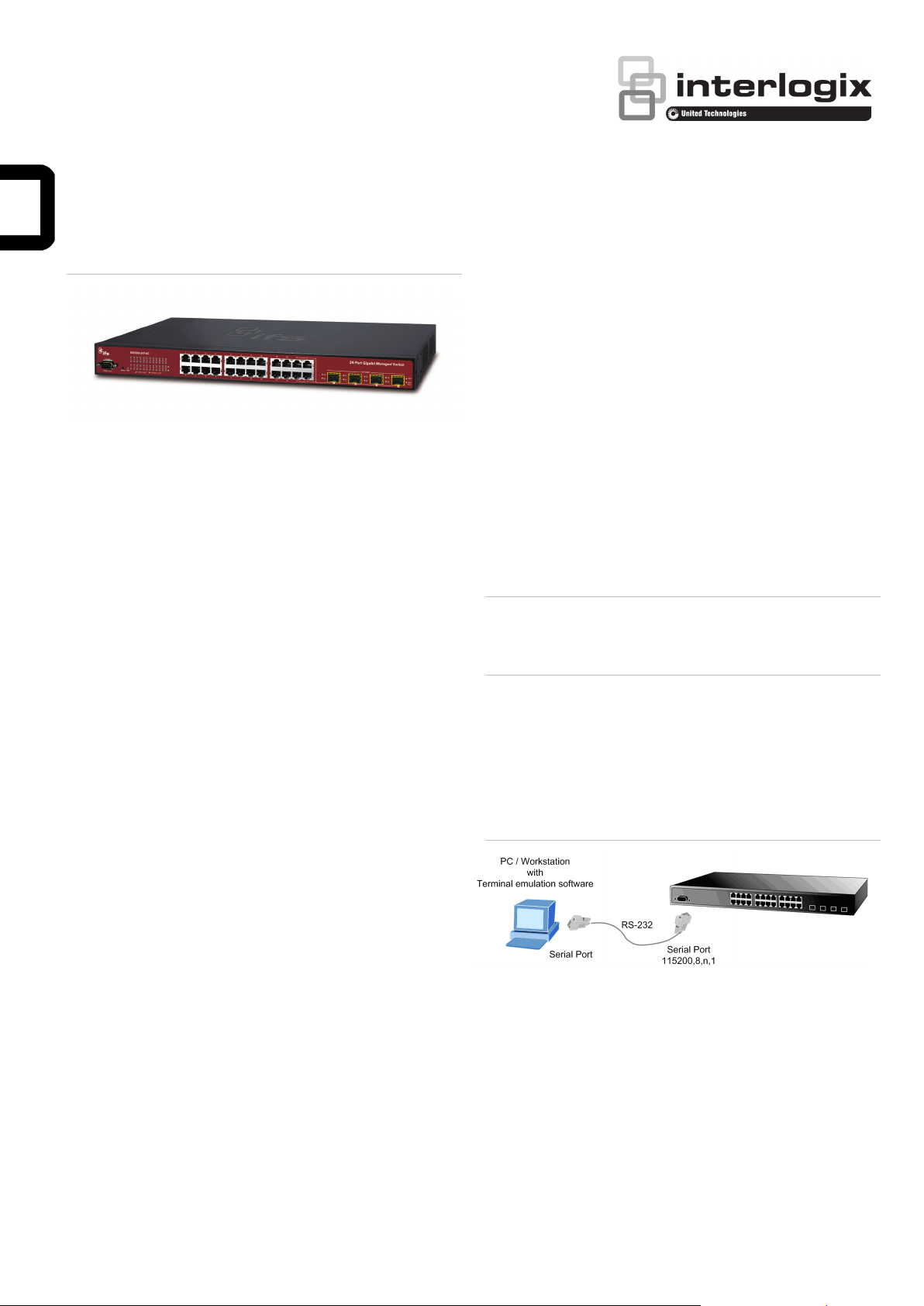
Terminal setup
To configure the system, connect a serial cable to a COM port
on a PC or notebook computer and to an RS232 type serial
port on the managed switch.
Figure 2: Console connectivity
Power cord x 1
SFP dust-proof cap x 4
If any of these are missing or damaged, contact your dealer
immediately. If possible, retain the carton including the original
packing materials for repacking the product in case there is a
need to return it to us for repair.
Requirements
The managed switch provides a remote login interface for
management purposes. The following equipment is necessary
for further management:
Workstations running Windows
2008 / 10, MAC OS X or later, Linux, UNIX, or other
platforms are compatible with TCP/IP protocols.
© 2018 United Technologies Corporation. P/N 1073385-EN • REV A • ISS 02MAR18
Interlogix is part of UTC Climate, Controls & Security, a unit of United Technologies Corporation. All rights reserved.
®
XP / 2003 / Vista / 7 / 8 /
A terminal program is required to make the software connected
to the managed switch. Windows' Hyper Terminal program
may be a good choice. The Hyper Terminal can be accessed
from the Start menu.
1. Click Start > Programs > Accessories > Hyper
Terminal.
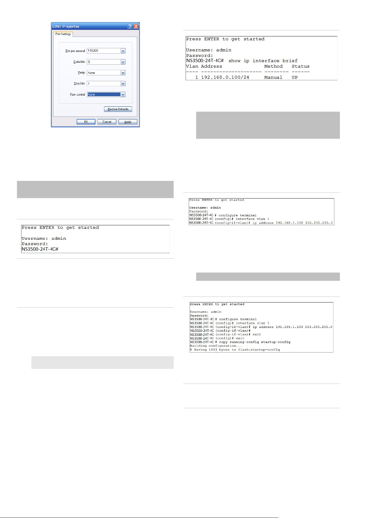
2. When the following screen appears, ensure that the COM
port is configured as shown below. Click OK when finished
with configuration.
Page 2
3. Log in to the console. After the terminal has been
connected to the device, power on the managed switch.
The terminal displays “running testing procedures”.
When the following dialog box in Figure 4 below appears,
type the factory default user name "admin" and password
“admin”.
Figure 4: IP information screen
Configuration of the IP address
3. At the “#” prompt, type the following command and press
Enter as shown in Figure 5.
NS3500-24T-4C # configure terminal
NS3500-24T-4C (config)# interface vlan 1
NS3500-24T-4C (config-if-vlan)# ip address 192.168.1.100
255.255.255.0
The previous command would apply the following settings
for the managed switch.
IP Address: 192.168.1.100
Subnet Mask: 255.255.255.0
User name: admin
Password: admin
Figure 3: Console login screen
Note:
1. For security purposes, change and memorize the new
password after this first setup.
2. Only commands in lowercase letters are accepted in the
console interface.
Configuring the IP address
The managed switch is shipped with the default IP address
shown below:
IP Address: 192.168.0.100
Subnet Mask: 255.255.255.0
To check the current IP address or modify a new IP address
for the managed switch, use the following procedures:
Display of the current IP Address
1. At the “#” prompt, type “show ip interface brief”.
Figure 5: Configuring the IP address screen
4. Repeat step 1 to check if the IP address has changed.
Store the current switch configuration
5. At the “#” prompt, type the following command and press
Enter.
# copy running-config startup-config
Figure 6: Saving current configuration command screen
If the IP is successfully configured, the managed switch applies
the new IP address setting immediately. Access the web
interface of the managed switch through the new IP address.
Note: If unfamiliar with the console command or the related
parameter, type “help” in the console to obtain the Help
description.
2. The screen displays the current IP address.
Starting web management
The section describes how to start up the web management
function for the managed switch. Note that the managed switch
is configured through an Ethernet connection. Ensure that the
manager computer is set to the same IP subnet address.
For example, if the default IP address of the managed switch is
192.168.0.100, then the manager computer should be set to
2 / 4 P/N 1073385-EN • REV A • ISS 02MAR18
Page 3

192.168.0.x (where x is a number between 1 and 254, except
100), and the default subnet mask is 255.255.255.0.
Figure 7: IP management diagram
Logging in to the managed switch
1. Use the Internet Explorer 8.0 or later Web browser and
type the IP address http://192.168.0.100 (the factorydefault IP address) to access the Web interface.
2. When the following dialog box appears, enter the default
user name “admin” and password “admin” (or the
password you have changed before) as shown in Figure 9
below.
Default IP Address: 192.168.0.100
Default User Name: admin
Default Password: admin
Figure 8: Login screen
Refer to the User Manual for further information about using
the web management interface.
Note: For security purposes, change and memorize the new
password after this first setup.
Saving the configuration
The running configuration file is stored in the RAM of the
managed switch. In the current version, the running
configuration sequence of running-config can be saved from
the RAM to FLASH by executing the Save Startup Config
command. After doing this, the running configuration sequence
becomes the startup configuration file (i.e., the saved
configuration).
3. After typing the password, the main screen appears as
shown in Figure 10 below.
Figure 9: Main web interface screen
4. The switch menu on the left side of the web page permits
access to all the functions and status provided by the
managed switch.
To save all applied changes and set the current configuration
as a startup configuration, the startup-configuration file is
loaded automatically across a system reboot.
1. Click System > Save Startup Config.
2. Click the Save Configuration button.
P/N 1073385-EN • REV A • ISS 02MAR18 3 / 4
Page 4

Resetting the switch to default
North America
T
E
W
Latin America
T
E
Europe, Middle East, and Africa
W
Australia
E
To reset the IP address to the default IP address
“192.168.0.100” and the user password to factory default mode
(default password is “admin”), press the hardware reset button
on the front panel for about 10 seconds. After the device is
rebooted, log in to the management Web interface within the
same subnet of 192.168.0.xx and default password. Note that
all the previous setups are erased after the factory default
reset.
Figure 10: Reset button
Contact information
+1 855.286.8889
techsupport@interlogix.com
www.interlogix.com/support
+1 561-998-6114
latam@interlogix.com
Select Contact Us at www.utcfssecurityproducts.eu
security.tech.support@interlogix.com.au
4 / 4 P/N 1073385-EN • REV A • ISS 02MAR18
 Loading...