

Page 1
8-Port 10/100/1000Mbps Indust r ial G igabit Ethernet Switch - NS3050-8P - User Manual
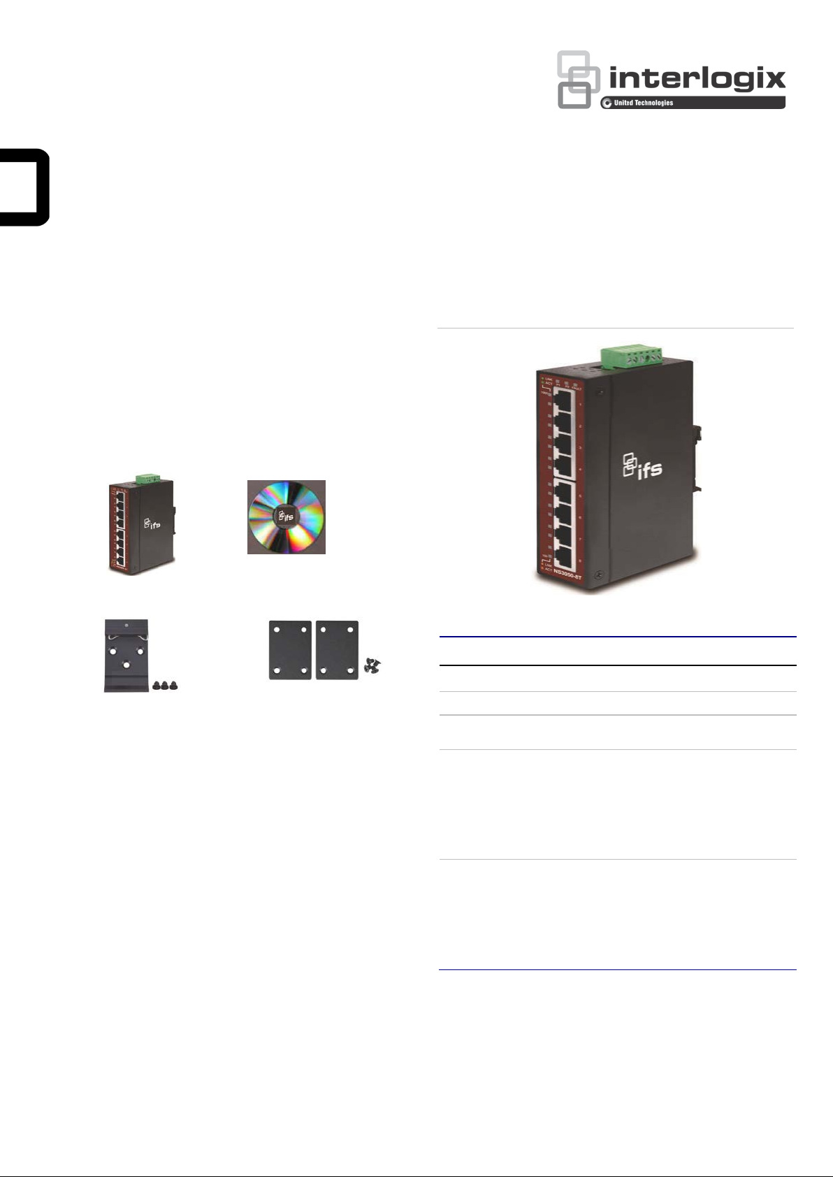
Figures 2-2 show the front panels of Industrial Gigabit Ethernet
Package Contents
Thank you for purchasing IFS 8-Port 10/100/1000T industrial
Gigabit Ethernet Switch, NS3050-8T. In the following section,
the term “Industrial Gigabit Ethernet Switch” means the
NS3050-8T.
Open the box of the Industrial Gigabit Ethernet Switch and
carefully unpack it. The box should contain the following items:
Industrial Gigabit Ethernet
Switch x 1
User's Manual x 1
Switches.
Figure 2-2: NS3050-8T Front Panel
DIN Rail Kit x 1
If any of these are missing or damaged, please contact your
dealer immediately; if possible, retain the carton including the
original packing material, and use them again to repack the
product in case there is a need to return it to us for repair.
Wall-mount Kit x 1
2. Hardware Introduction
2.1 Physical Dimensions
NS3050-8T dimensions (W x D x H): 135 x 87 x 32mm
See Figure 2.1 on page 6.
2.2 Switch Front Panel
The front panel of the Industrial Gigabit Ethernet Switch
consists of 5 or 8 auto-sensing 10/100/1000Mbps Ethernet
RJ45 ports. The LED Indicators are also located on the RJ45
ports of the Gigabit Ethernet Switch.
2.3 LED Indicators
LED Color Function
P1 Green Lit: indicates power 1 has power.
P2 Green Lit: indicates power 2 has power.
FAULT Red
1000 Green
100 Orange
(Note: 1) Notice the fault light will go out if you tie power 1 to
power 2 if you are not using redundant power.
Lit: indicates either power 1 or power 2 has no
power. (See Note: 1)
Lit: indicates the port is successfully
connecting to the network at 1000Mbps.
Off: indicates that the port is successfully
connecting to the network at 10Mbps or
100Mbps.
Blinking: indicates that the port is actively
sending or receiving data.
Lit: indicates the port is successfully
connecting to the network at 100Mbps or
10Mbps.
Off: indicates that the port is successfully
connecting to the network at 1000Mbps.
Blinking: indicates that the port is actively
sending or receiving data.
© 2016 United Technologies Corporation. P/N 1073226 • REV A • ISS 13SEP16
Interlogix is part of UTC Climate, Controls & Security, a unit of United Technologi es Corporat i on. Al l rights reserved.
Page 2
2.4 Switch Upper Panel
1 2 3 4 5
6
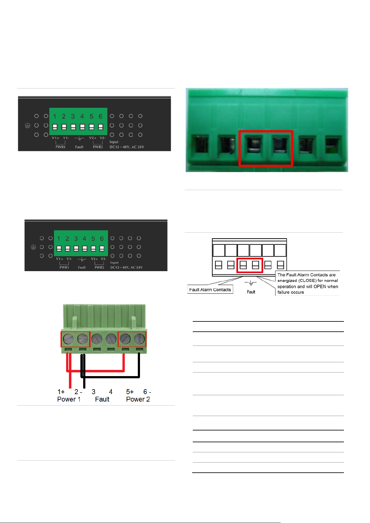
2.6 Wiring the Fault Alarm Contact
The upper panel of the Industrial Gigabit Ethernet Switch
consists of one terminal blo ck connect or within two DC power
inputs.
Figure 2-4 shows the upper panel of the Industrial Gigabit
Ethernet Switch.
Figure 2-4: Industrial Gigabit Ethernet Switch Upper Panel
2.5 Wiring the Power Inputs
The 6-contact terminal block connector on the top panel of
Industrial Gigabit Ethernet Switch is used for two DC
redundant power inputs. Please follow the steps below to insert
the power wire.
1. Insert positive and negative DC power wires into contacts
1 and 2 for Power 1 or 5, and 6 for Power 2.
The fault alarm contacts are in the middle of the terminal block
connector as the picture shows below. Inserting the wires, the
Industrial Gigabit Ethernet Switch will detect the fault status of
the power failure and then forms an open circuit. The following
illustration shows an application example for wiring the fault
alarm contacts.
Insert the wires into the fault alarm contacts
Note:
1. The wire gauge for the terminal block should be in the
range between 12 and 24 AWG.
V1+ V1 - V2 + V2 -
2. Tighten the wire-clamp screws for preventing the wires
from loosening.
Note
:
2. Alarm relay circuit accepts up to 30 V, max. 3 A currents.
2.7 Product Specifications
Hardware Specifications
10/100/1000BASE-T Ports 8
Dimensions (W x D x H) 135 x 87 x 32 mm
Weight 461g
Power Requirements
Power Consumption/
Dissipation
12 to 48 VDC, redundant power
with polarity reverse protection
function, 24 VAC power support
48 VDC @ 140 mA 6.72 W /
23 BTU
1. The wire gauge for the terminal block should be in the
Installation DIN rail kit and wall-mount ear
range between 12 and 24 AWG.
Switch Specifications
2. The device must be grounded.
3. The DC power input range is 12V ~ 48 VDC.
2 / 6 P/N 1073226 • REV A • ISS 13SEP16
Switch Processing Sch eme Store-and-Forward
Address Table 4K
Buffer 1.5Mbits SRAM packet buffer
Page 3

Flow Control
Back pressure for half duplex
Switch
Throughput (packet per second)
Jumbo Frame
Network Cables
m,
m,
Standards Conformance
Standards Compliance
Temperature
Humidity
Regulat
Fabric 16Gbps
9K
IEEE 802.3x pause frame for full
duplex
11.9Mpps
10/100/1000BASE-T:
Cat3, 4, 5, 5e, 6 UTP cable (100
max.)
EIA/TIA-568 100-ohm STP (100
max.)
IEEE 802.3 Ethernet
IEEE 802.3u Fast Ethernet
IEEE 802.3ab Gigabit Ethernet
IEEE 802.3x Full-Duplex Flow
Control
Operating: -40 to +75 °C
Storage: -40 to 75 °C
Operating: 5% to 95%, Storage:
5% to 95% (non-condensing)
Step 3: Check whether the DIN-rail is securely on the track.
ory Compliance FCC Part 15 Class A, CE
3. INSTALLATION
3.1 DIN-rail Mounting Installation
You need to screw the DIN-rail on the Industrial Gigabit
Ethernet Switch. To replace the wall-mount application with
DIN-rail application on Industrial Gigabit Ethernet Switch,
please refer to the following figures to screw the DIN-rail on the
Industrial Gigabit Ethernet Switch.
To hang the Industrial Gigabit Ethernet Switch, please follow
the steps below:
Step 1: Screw the DIN-rail on the Industrial Gigabit Ethernet
Switch.
To remove the Industrial Gigabit Ethernet Switch from the
track, follow the steps below:
Step 1: Carefully pull out the bottom of DIN-rail to remove it
from the track.
3.2 Wall-mount Plate Mounting
Step 2: Place the bottom of DIN-rail lightly into the track.
P/N 1073226 • REV A • ISS 13SEP16 3 / 6
To install the Industrial Gigabit Ethernet Switch on the wall,
please follow the steps below.
Step 1: Remove the DIN-rail from the Industrial Gigabit
Ethernet Switch. Loosen the screws to remove the DINrail.
Step 2: Place the wall-mount plate on the rear panel of the
Industrial Gigabit Ethernet Switch.
Page 4

Step 3: Use the screws to screw the wall-mount plate on the
Industrial Gigabit Ethernet Switch.
Step 4: Use the hook holes at the corners of the wall-mount
plate to hang the Industrial Gigabit Ethernet Switch on the
wall.
Step 5: To remove the wall-mount plate, reverse the steps
above.
4. TROUBLESHOOTING
This chapter contains information to help you solve issues. If
the Industrial Gigabit Et hernet Sw itch is not functioning
properly, make sure the Industrial Gigabit Ethernet Switch was
set up according to instructions in this manual.
The per port LED is not lit
Solution:
Check the cable connection of the Industrial Gigabit
Ethernet Switch.
Performance is bad
Solution:
Check the speed duplex mode of the partner device. The
Industrial Gigabit Ethernet Switch is run in autonegotiation mode and if the partner is set to half duplex,
then the performance will be poor.
Per port LED is lit, but the traffic is irregular
Solution:
sure the cable is the right type. Turn off the power. After a
few moments, turn on the power again.
APPENDIX A: NETWORKING CONNECTION
A.1 Switch’s RJ45 Pin Assignments
1000Mbps, 1000BASE-T
Contact MDI MDI-X
1 BI_DA+ BI_DB+
2 BI_DA- BI_DB3 BI_DB+ BI_DA+
4 BI_DC+ BI_DD+
5 BI_DC- BI_DD6 BI_DB- BI_DA7 BI_DD+ BI_DC+
8 BI_DD- BI_DC-
10/100Mbps, 10/100BASE-TX
RJ45 Connector pin assignment
MDI
Contact
1 Tx + (transmit) Rx + (receive)
2 Tx - (transmit) Rx - (receive)
3 Rx + (receive) Tx + (transmit)
4, 5 Not used
6 Rx - (receive) Tx - (transmit)
7, 8 Not used
Media Dependent
Interface
A.2 RJ45 Cable Pin Assignments
MDI-X
Media Dependent
Interface -Cross
Check that the attached device is not set to dedicate full
duplex. Some devices use a physical or software switch to
change duplex modes. Auto-negotiation may not
recognize this type of full-duplex setting.
The Industrial Gigabit Ethernet Switch doesn’t connect to
the network
Solution:
The standard RJ45 receptacle/connector
There are 8 wires on a standard UTP/STP cable and each wire
is color-coded. The following shows the pin allocation and color
Check per port LED on the Industrial Gigabit Ethernet
Switch. Try another port on the Industrial Gigabit Ethernet
of straight-through cable and cross ov er cable con ne ctio n:
Switch. Make sure the cable is installed properly. Make
4 / 6 P/N 1073226 • REV A • ISS 13SEP16
Page 5

Figure A-1: Straight-through and Crossover Cable
Straight-through Cable
SIDE 1
SIDE 2
SIDE 1
1 = White / Orange
1 = White / Orange
SIDE 2
Crossover Cable
SIDE 1
SIDE 2
SIDE 1
1 = White / Orange
1 = White / Green
SIDE 2
Manufacturer
FCC complian ce
generates, uses, and can radiate radio frequency
communications. Operation of this equipment in a
FCC conditions
ACMA compliance
Canada
CAN
Certification
European Union
directives
12004/108/EC (EMC directive): Hereby, UTC Fire
unsorted municipal waste in the European Union.
Trademarks and
patents
1 2 3 4 5 6 7 8
1 2 3 4 5 6 7 8
1 2 3 4 5 6 7 8
1 2 3 4 5 6 7 8
Please make sure your connected cables are with the same pin assignment and color as the above
Regulatory information
Interlogix.
2955 Red Hill Avenue, Costa Mesa, CA 92626
5923, USA
Authorized EU manufacturing representative:
UTC Fire & Security B.V.
Kelvinstraat 7, 6003 DH Weert, The Netherlands
Class A: This equipment has been tested and
found to comply with the limits for a Class A
digital device, pursuant to part 15 of the FCC
Rules. These limits are designed to provide
reasonable protection against harmful
interference when the equipment is operated in a
commercial environment. This equipment
energy and, if not installed and used in
accordance with the instruction manual, may
cause harmful interference to radio
residential area is likely to cause harmful
interference in which case the user will be
required to correct the interference at his own
expense.
This device complies with Part 15 of the FCC
Rules. Operation is subject to the following two
conditions:
(1) This device may not cause harmful
interference.
(2) This Device must accept any interference
received, including interference that may cause
undesired operation.
P/N 1073226 • REV A • ISS 13SEP16 5 / 6
Notice! This is a Class A product. In a domestic
environment this product may cause radio
interference in which case the user may be
required to take adequate measures.
This Class A digital apparatus complies with
ICES-003 (A)/NMB-3 (A).
Cet appareil numérique de la classe A est
conforme à la norme CAN ICES-003 (A)/NMB-3
(A).
2 = Orange
3 = White / Green
4 = Blue
5 = White / Blue
6 = Green
7 = White / Brown
8 = Brown
2 = Orange
3 = White / Green
4 = Blue
5 = White / Blue
6 = Green
7 = White / Brown
8 = Brown
& Security declares that this device is in
compliance with the essential requirements and
other relevant provisions of Directive
2004/108/EC.
2012/19/EU (WEEE directive): Products marked
with this symbol cannot be disposed of as
For proper recycling, return this product to your
local supplier upon the purchase of equivalent
new equipment, or dispose of it at designated
collection points. For more information see:
www.recyclethis.info.
2013/56/EU & 2006/66/EC (battery directi ve):
This product contains a battery that cannot be
disposed of as unsorted municipal waste in the
European Union. See the product documentation
for specific battery information. The battery is
marked with this symbol, which may include
lettering to indicate cadmium (Cd), lead (Pb), or
mercury (Hg). For proper recycling, return the
battery to your supplier or to a designated
collection point. For more information see:
www.recyclethis.info.
The trade names used in this document may be
trademarks or registered trademarks of the
manufacturers or vendors of the respective
products.
2 = Orange
3 = White / Green
4 = Blue
5 = White / Blue
6 = Green
7 = White / Brown
8 = Brown
2 = Green
3 = White / Orange
4 = Blue
5 = White / Blue
6 = Orange
7 = White / Brown
8 = Brown
Contact information
For contact information, see www.interlogix.com or
www.utcfssecurityproducts.eu.
Page 6

Physical Dimensions
Figure 2.1: NS3050-8T dimensions (W x D x H): 135 x 87 x 32mm
6 / 6 P/N 1073226 • REV A • ISS 13SEP16
 Loading...