

Page 1
Ethernet Interface Installation Instructions
Product summary
The Ethernet Interface module (60-938) is an Ethernet module
designed to provide an additional reporting method for Simon
panels. The module connects to a DSL or cable modem
(broadband) and reports events to the premisesconnect.com
web site and up to two Osborne-Hoffman (OH2000E) network
receivers.
Premisesconnect.com is used by:
• Installers - to aid in installation and maintenance of
security systems.
• Dealers - to simplify customer and account management.
• Customers - to receive event notifications and to control
their security system.
Ethernet Interface Module Setup
Perform the following steps to setup the Ethernet Interface
module. Each step is described in detail in this manual.
1. Installation - Installing the Ethernet Interface module into
the Simon® control panel.
2. Activation - Activating the communication channel
between the module and the Simon panel.
Installation
Requirements
• Broadband Internet connection (DSL or cable modem)
• An available 10-Base-T or 10/100-Base-T Ethernet Port
• Simon panel with software version 4.0 or later
Tools and Supplies
• Small blade and Phillips screwdriver
• Screws for mounting module
• Standard (non-crossover) Category 5e Ethernet cable with
RJ45 connectors
• Power/Bus cable
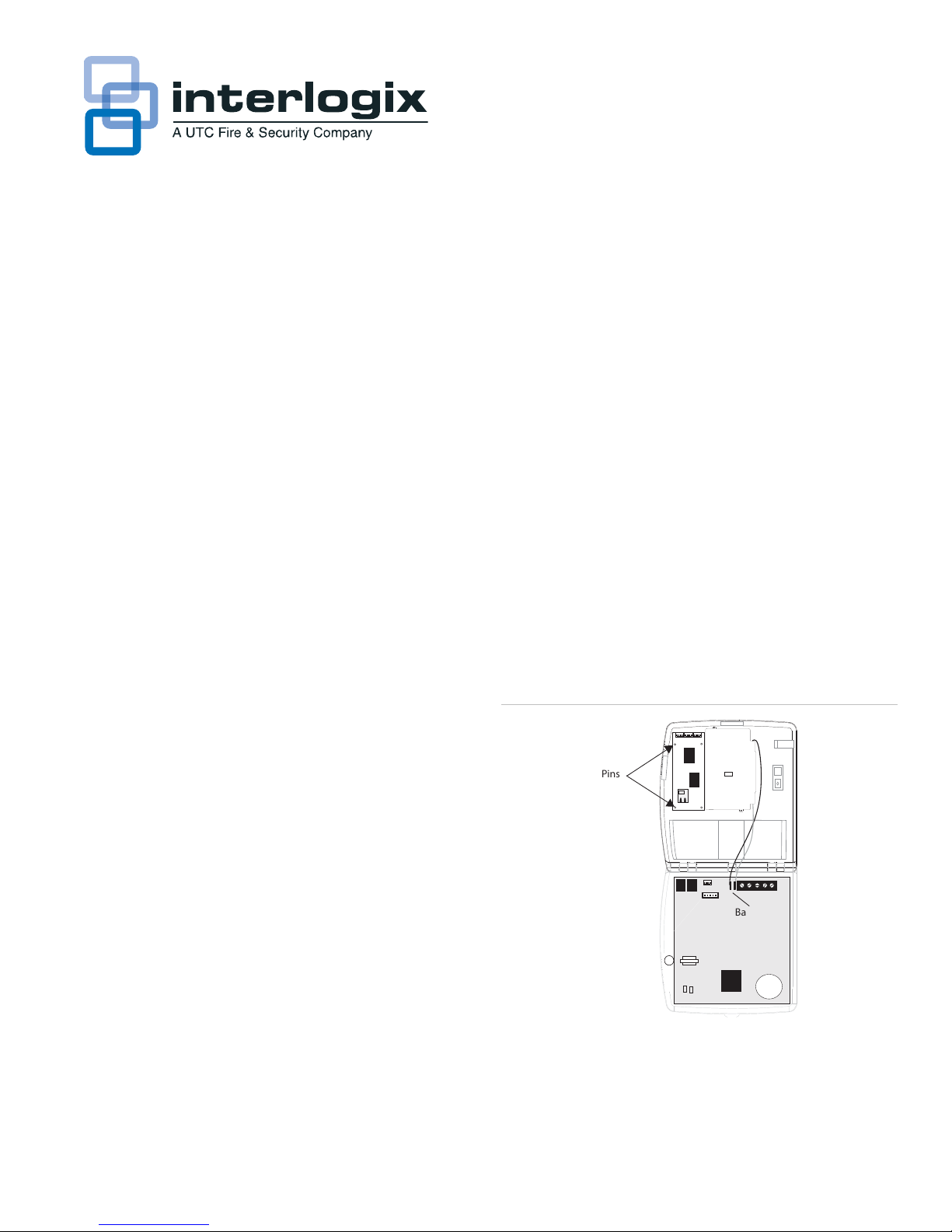
Mounting and Wiring
Figure 1: Mounting the Ethernet Interface Module
Pins
3. Connection - Connecting the Ethernet Interface Module Simon Panel combination to a network.
4. Registration - Registering the system on the
premisesconnect.com website.
Note: Dealers are required to have a contract with UTC Fire &
Security before accessing the premisesconnect.com web site.
Upon entering into a contract, the dealer is supplied with a
Dealer ID, which is required for system registration on the web
site.
P/N 466-2161 • REV D • January 2011 1
Battery
Connection
To mount the Ethernet Interface module inside a
Simon panel:
1. Remove AC power.
Page 2
2. Open the panel cover.
6. Reconnect the backup battery.
3. Release the top chassis latch from the back plastic with a
small screwdriver (twist the screwdriver).
4. Flip the front cover down until the back plastic is exposed.
5. Disconnect the backup battery.
6. With the Ethernet connector on the module facing the
hinge of the panel, align the holes on the left side of the
module with the plastic pins on the left side of the panel
back plastic.
7. Secure the module to the screw posts on the panel
through the holes on the right of the module using the
included mounting screws.
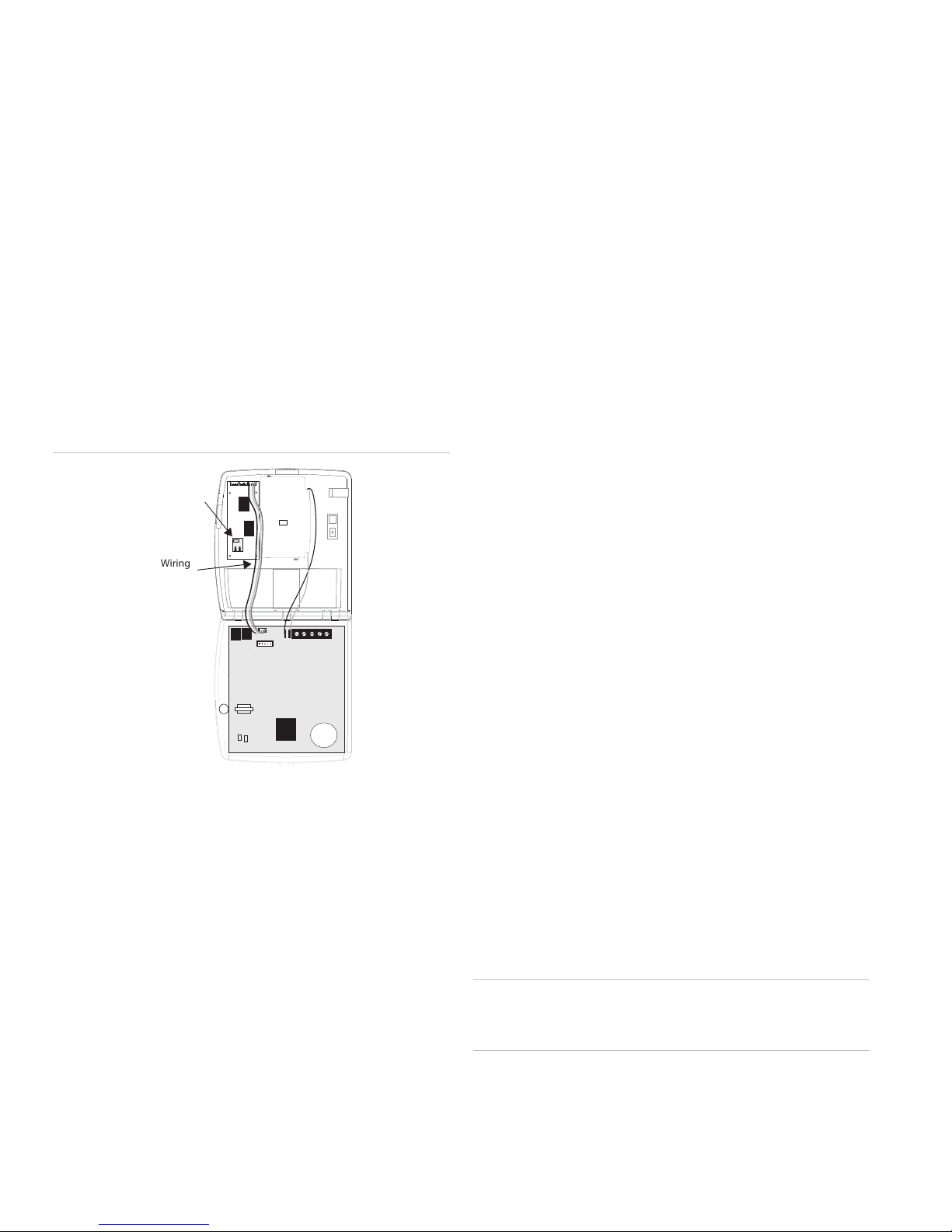
To wire the Ethernet Interface module to a Simon
panel:
Figure 2: Wiring the Ethernet Interface Module
Ethernet
Connector
7. Close the panel cover.
8. Apply AC power.
Connection
Connecting the Ethernet Interface Module to a
Network
There are several possible network configurations the SimonEthernet Interface module System may take. The following are
guidelines for connecting the system to a network.
• The module must be connected to an available 10-Base-T
or 10/100-Base-T Ethernet Port that leads to the Internet.
(The port cannot be labeled “WAN” or “Uplink”.)
• The module is not compatible with USB.
• If Remote Option 5 is On there must be a DHCP Server on
the local network. (A DHCP Server is usually built into
routers.) If Remote Option 5 is off, Remote Option 7 must
be programmed with a legal Static IP Address.
Wiring
Harness
1. Connect one end of the included wiring harness to the
right 4 pins on the top of the module. The red wire on the
harness should be to the right.
2. Connect the other end of the wiring harness to the pins
located just to the right of the phone jacks on the panel.
The red wire on the harness should be to the right.
3. Connect one end of the Category 5e Ethernet cable to the
Ethernet connector on the bottom left of the module.
4. Connect the other end of the Ethernet cable to an
available Ethernet port on your cable or DSL modem, hub,
switch or router (see Figure 3 on page 3).
For UL Listed Systems
• The network connection must be always on and not
require the use of the public switched telephone network
to make a “dial up” connection.
• All devices between the Ethernet Interface and the
transmission line (ethernet port or “hub”, router, cable
modem, etc.) must be UL listed models and not receive
power from a switched outlet.
• Supervision signals between the panel and the
supervising station receiver (central station) must be
managed by the central station and not an intermediary
network agent, device or service.
• Lost communication between the system and the reporting
station will be indicated at the reporting station within 90
seconds.
• The communication path between the panel and the
receiver can be either DACT or internet. One is not a
backup for the other.
Caution: If connecting devices (“hub”, router, cable modem)
do not have battery backup. The system will lose
communication with the reporting station if AC power is lost.
Make any other wiring or phone connections at this time.
5.
See the Simon Installation Instructions for necessary
connections.
2 Ethernet Interface Installation Instructions
Page 3

Setting the Simon Panel Options
Simon options 90-92 must be programmed properly in order for
the Simon / Ethernet Interface system to report properly.
If the Simon/Ethernet Interface module system
reports to a network central station receiver:
• Simon Option 90 must be set to 0 or 1. If the system will
report to an additional network central station receiver,
Option 91 must also be set to 0 or 1.
• Remote Options 27-31 must be set properly if the system
reports through Comm Channel 1. Options 32-36 must be
set properly if the system uses Comm Channel 2.
Registration
Registering the Ethernet Interface Module
Registration is necessary if the system will be communicating
with the premisesconnect.com website. Registration is not
necessary if the system will be communicating only with a
TCP/IP central station receiver.
There are step-by-step registration instructions on the
premisesconnect.com website.
To access registration instructions online
If the Simon/Ethernet Interface module system
reports to the premisesconnect.com website:
Simon Option 92 must be set to 0.
Setting up DHCP
Remote options 5 and 7-9 must be set according to the
configuration of the available network. See the Glossary
section in the back of this document for an explanation of
DHCP.
If the network DOES NOT have a DHCP server
installed:
• Remote Option 5 must be Off.
• Remote Options 7, 8 and 9 must be set properly. See
remote Option 7 IP Address (“Remote Option 6- Reset
Module Command” on page 7), Remote Option 8- Static
Router IP Address (“Remote Option 7- Static Module IP
Address”) on page 8 and Remote Option 9- Static Subnet
Mask (“Remote Option 8- Static Router IP Address” on
e 8).
pag
Figure 3: Residential Simon-Ethernet Interface configuration
1. Login as a Dealer or Service.
2. Click on Advanced Admin Features
3. Click on Registration Setup
Identification
Each Simon panel - Ethernet Interface module combination
(system) is identified by its Account Number, Dealer ID and
Line Number. These must be set before attempting to register
the system.
Account Number
he Account Number (Simon Option 7) is a unique 10-
T
character alphanumeric identifier programmed at the panel.
This is the same Account Number used by standard central
station receivers.
The Account Number may be pre-programmed. Verify there is
no Account Number programmed before setting the Account
Number.
To verify an Account Number is programmed:
1. Enter Utility Access Code 1 (Dealer Code).
2. Press Option #.
Hub, Switch or Router
Cable or DSL
Modem
Internet
Standard
Ethernet
Modem and Router
may be one Device
Modem, Router and
Switch may be one
Device
Cable
3
! #
5
. /
$
$
+
-
3
%&
'( +(
Simon-Ethernet Interface Module System
Ethernet Interface Installation Instructions 3
Home Computer
3. Press Option repeatedly until you hear “Option 7” or press
0, then 7.
4. Listen for the value of the option. (Press Cancel to stop
the panel from listing option values.)
To set the Account Number:
1. If not in program mode, enter Utility Access Code 1
(Dealer Code).
2. Press Add.
3. Press Option #.
Page 4

4. Press Option repeatedly until you hear “Option 7” or press
0, then 7.
5. Enter the Account Number using the numbered keys.
Press 9 then the Minutes + button to enter letters (A-F).
Pressing the Minutes + button repeatedly scrolls through
the alphanumeric list (A-F, 0-9).
Line Number
he Line Number (Remote Option 4) is a numeric identifier that
T
can be up to 10 digits long.
The Line Number may be pre-programmed. Verify there is no
Line Number programmed before setting the Line Number.
6. Press Done when the Account Number is entered.
Note: The Contact ID reporting method does not allow the use
of the letter A in account numbers.
See the Simon Installation Instructions for complete panel
programming instructions.
Dealer ID
he Dealer ID (Remote Option 3) is a numeric identifier
T
assigned by UTC Fire & Security that can be up to 10 digits
long. It is unique for each dealer or installer. The Dealer ID
must match an existing Dealer ID stored on the server.
The Dealer ID may be pre-programmed. Verify there is no
Dealer ID programmed before setting the Dealer ID.
To verify the Dealer ID:
1. Enter Utility Access Code 1 (Dealer Code) if you are not
already in program mode.
2. Press Option #.
3. Press Test. This switches to the Remote or Ethernet
Interface options menu and the panel begins announcing
the values of all the remote options.
To verify the Line Number:
1. Enter Utility Access Code 1 (Dealer Code) if you are not
already in program mode.
2. Press Option #.
3. Press Test. This switches to the Remote or Ethernet
Interface options menu and the panel begins announcing
the values of all the remote options.
4. Listen until you hear the value of Remote Option 4. (Press
Cancel to stop the panel from listing remote option
values.)
To set the Line Number:
1. Enter Utility Access Code 1 (Dealer Code) if you are not
already in program mode.
2. Press Add.
3. Press Option #.
4. Press Test. This switches to the Remote or Ethernet
Interface options menu.
5. Press Option # repeatedly until you hear “Remote Option
4...”
4. Listen until you hear the value of Remote Option 3. (Press
Cancel to stop the panel from listing remote option
values.)
To set the Dealer ID:
1. Enter Utility Access Code 1 (Dealer Code) if you are not
already in program mode.
2. Press Add.
3. Press Option #.
4. Press Test. This switches to the Remote or Ethernet
Interface options menu.
5. Press Option # repeatedly until you hear “Remote Option
3...”
6. Enter the Dealer ID using the numbered keys.
7. Press Done. The panel will repeat the Dealer ID.
6. Enter the Line Number using the numbered keys.
7. Press Done. The panel will repeat the Line Number.
Creating a Premisesconnect.com Account
You can create an account for the system before or after
installing and registering the system at the premises. Typically
it will be done before installation, so any problems can be
resolved before installation. Follow the procedures on the
premisesconnect.com website to create an account.
Note: Account ID must be the same as the Account number
(Simon Option 07) programmed into the Simon panel.
The following is some of the information that will have to be
added when creating an account:
• Account name, address and phone
• Account ID
• Primary Contact
4 Ethernet Interface Installation Instructions
Page 5

Registering the System
Before selecting Submit in Step 4 of the online registration
process, the following steps must be completed.
11. Press Done. The panel announces “Remote Option 2 OK.”
Wait 30 seconds before proceeding to Verify Registration.
Verify Registration
To register or re-register the Ethernet Interface
module:
1. Open the panel cover.
2. Enter Utility Access Code 1 (Dealer Code) if you are not
already in program mode.
3. Press Option #.
4. Press Test. The system will begin listing the remote
options and their values.
5. Listen until you hear the phrase “Remote Option 1 is off.”
Important: Remote Option 1 must be off in order for the
module to register successfully.
6. Press Cancel to stop the panel from announcing option
values.
7. Press Add.
8. Press Option #.
9. Press Test.
10. Press Option # repeatedly until you will hear the panel
announce “Remote Option 2”.
To verify the system was registered properly at the
panel:
1. Press Option #.
2. Press Test. The system will begin listing the remote
options and their values.
3. Listen until you hear the phrase “Remote Option 1 is on.”
4. Press Cancel so stop the panel from announcing option
values.
If the panel says “Remote Option 1 is off”, the system was not
registered properly. Verify all connections are correct, Simon
Option 89 is On, the LED’s on the module and Ethernet
connector are flashing (must open panel cover to verify), and
the Account Number is not already in use; then try to register
the system again. See the Troubleshooting section for more
information.
To verify the system was registered properly:
Follow the procedures on the premisesconnect.com website.
Programming Options Reference
The following options are used to customize the Ethernet Interface module and are programmed at the panel
Table 1: Programming options
Option No. Option Default Range Desired Setting
Simon Option 89 Serial Port Protocol Off On/Off
Simon Option 90 Comm Channel 1 Reports Off 0, 1, Off
Simon Option 91 Comm Channel 2 Reports Off 0, 1, Off
Simon Option 92 Comm Channel 3 Reports Off 0, Off
Remote Option 1 Module Registration Status Off On/Off
Remote Option 2 Register Module Command N/A N/A
Remote Option 3 Dealer ID 000 1-10-digit numeric
Remote Option 4 Line Number 0001 1-10 digit numeric
Remote Option 5 DHCP On/Off On On/ Off
Remote Option 6 Reset Module Command N/A N/A
Remote Option 7 Static Module IP Address 192.168.000.049 12-digit, 4 octet
Remote Option 8 Static Router IP Address 192.168.000.001 12-digit, 4 octet
Remote Option 9 Static Subnet Mask 255.255.255.000 12-digit, 4 octet
Remote Option 10 Current Module IP Address Dynamic 12-digit numeric
Ethernet Interface Installation Instructions 5
Page 6

Op
tion No. Option Default Range Desired Setting
Remote Option 11 Current Router IP Address Dynamic 12-digit numeric
Remote Option 12 Current Subnet Mask Dynamic 12-digit numeric
Remote Option 13 MAC Address Dynamic 12-digit hexidecimal
Remote Option 14 Proxy Server IP Address 000.000.000.000 12-digit, 4 octet
Remote Option 15 Proxy Server Port 0080 4-digit numeric, 0000-9999
Remote Option 16 Clear Module Memory Command N/A N/A
Remote Option 17 Main Server IP Address 198.204.22.184 12-digit, 4 octet
Remote Option 18 Main Server Port 0080 4-digit numeric, 0000-9999
Remote Option 19 Ping Server IP Address 198.204.22.185 12-digit, 4 octet
Remote Option 20 Ping Server Port 0080 4-digit numeric, 0000-9999
Remote Option 21 Ping Page Base Name ping1 10-character alphanumeric
Remote Option 22 Main Server Page Base Name simon3 10-character alphanumeric
Remote Option 23 Registration Page Base Name gwreg 10-character alphanumeric
Remote Option 24 Ping Page Extension aspx 5-character alphanumeric
Remote Option 25 Main Server Page Extension aspx 5-character alphanumeric
Remote Option 26 Registration Page Extension aspx 5-character alphanumeric
Remote Option 27 Receiver 1 IP Address 000.000.000.000 12-digit, 4 octet
Remote Option 28 Receiver 1 Number 0001 4-digit, 0000, 0020-9999
Remote Option 29 Receiver 1 Poll Period 0000 4-digit, 0000, 0020-9999
Remote Option 30 Receiver 1 Port 9999 4-digit, 0000-9999
Remote Option 31 Receiver 1 Format 0 0, 1
Remote Option 32 Receiver 2 IP Address 000.000.000.000 12-digit, 4 octet
Remote Option 33 Receiver 2 Number 0001 4-digit, 0000-9999
Remote Option 34 Receiver 2 Poll Period 0000 4-digit, 0000, 0020-9999
Remote Option 35 Receiver 2 Port 9999 4-digit, 0000-9999
Remote Option 36 Receiver 2 Format 1 0, 1
Remote Option 37 Ethernet Interface Software Version 6 characters
Remote Option 38 Ping Page Directory Name Ping 7 characters
Remote Option 39 Main Page Directory Name Gateway 7 characters
Remote Option 40 Registration Page Directory Name Gateway 7 characters
with the module through the Simon serial port. Leave the
Simon Panel Options
option Off to allow downloader programming through a direct
connection to the panel serial port.
These options are programmed on a Simon panel or through
Enterprise Downloader version 2.2 or later and affect how the
panel interacts with the Ethernet Interface module.
Note: The Ethernet Interface or Remote Options will not be
programmable through Enterprise Downloader version 2.2
Option 89 - Serial Port Protocol
Default = Of
f; Range = On/Off
This option enables Simon to communicate with the Ethernet
Option 90 - Comm Channel 1 Reports
Default = Of
f; Range = 0, 1, Off
This option determines which reports are ultimately sent to the
network central station receiver 1 by the Ethernet Interface
module. Set this option to 0 to have Simon send all reports to
Comm Channel 1 (network receiver 1) of the module. Set it to
1 to send only alarms and manual communication tests to the
module.
Interface module. Turn the option On to allow communication
6 Ethernet Interface Installation Instructions
Page 7

Option 91 - Comm Channel 2 Reports
Remote Option 2- Register Module Command
Default = Off; Range = 0, 1, Off
This option determines which reports are ultimately sent to the
network central station receiver 2 by the Ethernet Interface
module. Set this option to 0 to have Simon send all reports to
Comm Channel 2 (network receiver 2) of the module. Set it to
1 to send only alarms and manual communication tests to the
module.
Option 92 - Comm Channel 3 Reports
Default = Of
This options determines which reports are ultimately sent to
the premisesconnect.com website by the Ethernet Interface
module. Set this option to On to have Simon send all reports to
Comm Channel 3 (premisesconnect.com).
f; Range = 0/Off
Other Simon Options
If your Simon-Ethernet Interface module system connects to
the premisesconnect.com website, the following options may
also be set to On depending on the configuration of the
system:
• Option 20 - Phone Test
• Option 21 - Opening Reports
• Option 22 - Closing Reports
• Option 23 - Forced Arm Report
• Option 24 - AC Fail
• Option 25 - CPU Low Battery
• Option 45 - Sensor Alarm Restoral
Refer to the Simon Installation Instructions for more
information.
Registration Options
Note: “ACMD” is spoken when the panel lists Remote Options
2, 6 and 16.
Registration is necessary if the system will be communicating
with the premisesconnect.com web site. Registration is not
necessary if the system will only be communicating with a
TCP/IP central station receiver. The following options (Remote
Options 1-4), as well as Simon Option 07 (Account Number)
are used to register the system.
lt = N/A; Range = N/A
Defau
Used to register the Ethernet Interface module.
1. Press Add
2. Press Option #
3. Press Test
4. Press Option # until panel says “Remote Option 2...”
5. Press Done to register the module.
Remote Option 3- Dealer ID
Defau
lt = 000; Range = 1-10-digit numeric
The Dealer ID is unique to each installer and is assigned by
UTC Fire & Security. The Dealer ID must match an existing
Dealer ID stored on the premesisconnect.com system.
Remote Option 4- Line Number
Defau
lt = 0001; Range = 1-10-digit numeric
The Line Number is a 1 to 10-digit numeric identifier linked to
the primary reporting channel number of the panel. It is used
as a prefix to the panel Account Number.
Module Options
The following options are used to customize the operation of
the Ethernet Interface module.
Remote Option 5- DHCP On/Off
Default = On;
DHCP is used to assign an IP address to the Ethernet
Interface module automatically on a network containing a
DHCP Server (your router typically will have a built-in DHCP
Server). Typically DHCP should be left On. Remote Options 7,
8 and 9 must be programmed if DHCP is off.
Note: When this option is changed, it may be necessary to
reset the module (Remote Option 6) in order for the change to
take effect.
Remote Option 6- Reset Module Command
lt = N/A; Range = N/A
Defau
Range = On/Off
Remote Option 1- Module Registration Status
Default = Of
When the Ethernet Interface module is successfully registered
this option is switched On automatically. This option must be
Off before attempting to register or re-register the Ethernet
Interface module.
Ethernet Interface Installation Instructions 7
f; Range = On/Off
Used to reset the Ethernet Interface module.
1. Press Add
2. Press Option #
3. Press Test
4. Press Option # until panel says “Remote Option 6...”
Page 8

5. Press Done to reset the module.
Resetting the module does not clear its memory.
This option stores the current Subnet Mask of the Ethernet
Interface module. This option cannot be programmed and is for
review only.
Remote Option 7- Static Module IP Address
Defau
lt = 192.168.000.049; Range = 12-digit, 4 octet
When DHCP is Off, this option sets the IP address of the
Ethernet Interface module. This option is not used if DHCP is
On.
Note: When programming an IP address, 3 digits must be
used for each octet. An address of 10.1.8.100 would be
programmed at the panel as “010.001.008.100”. It is not
necessary to enter the periods.
Remote Option 8- Static Router IP Address
Defau
lt = 192.168.000.001; Range = 12-digit, 4 octets
When DHCP is Off, this option sets the router IP address used
by the Ethernet Interface module. This option is not used if
DHCP is On.
Note: When programming an IP address, 3 digits must be
used for each octet. An address of 10.1.8.100 would be
programmed at the panel as “010.001.008.100”. It is not
necessary to enter the periods.
Remote Option 13- MAC Address
Defau
lt = Dynamic; Range = 12-digit hexidecimal
This option stores the current MAC address of the Ethernet
Interface Module. This option cannot be programmed and is for
review only.
Remote Option 14- Proxy Server IP Address
lt = 000.000.000.000; Range = 12-digit, 4 octet
Defau
When a proxy server is used to communicate with the Internet,
enter the IP address of the proxy server in this option. Leave
this option set to 000.000.000.000 when not using a proxy
server.
Note: When programming an IP address, 3 digits must be
used for each octet. An address of 10.1.8.100 would be
programmed at the panel as “010.001.008.100”. It is not
necessary to enter the periods.
Remote Option 15 - Proxy Server Port
lt = 0080; Range = 4-digit numeric, 0000-9999
Defau
Remote Option 9- Static Subnet Mask
Defau
lt = 255.255.255.000; Range = 12-digit, 4 octets
When DHCP is Off, this option sets the subnet mask used by
the Ethernet Interface module. This option is not used if DHCP
is On.
Note: When programming an IP address, 3 digits must be
used for each octet. An address of 10.1.8.100 would be
programmed at the panel as “010.001.008.100”. It is not
necessary to enter the periods.
Remote Option 10- Current Module IP Address
Defau
lt = Dynamic; Range = 12-digit numeric
This option stores the current IP address of the Ethernet
Interface module. This option cannot be programmed and is for
review only.
Remote Option 11- Current Router IP Address
Defau
lt = Dynamic; Range = 12-digit numeric
This option stores the current IP address of the router through
which the Ethernet Interface module is connected. This option
cannot be programmed and is for review only.
Remote Option 12- Current Subnet Mask
Enter the TCP port the proxy server uses to communicate with
the Ethernet Interface module.
Remote Option 16 - Clear Module Memory Command
lt = N/A; Range = N/A
Defau
Used to clear the Ethernet Interface module memory.
1. Press Add
2. Press Option #
3. Press Test
4. Press Option # until panel says “Remote Option 16...”
5. Press Done to clear the Ethernet Interface module
memory.
This sets all options to their factory default settings.
Remote Option 17 - Main Server IP Address
Defau
lt = 198.204.22.184; Range = 12-digit, 4 octet
This option stores the IP address of the server on which
premisesconnect.com is located. This option is normally set at
the factory.
Note: When programming an IP address, 3 digits must be
used for each octet. An address of 10.1.8.100 would be
lt = Dynamic; Range = 12-digit numeric
Defau
8 Ethernet Interface Installation Instructions
Page 9

programmed at the panel as “010.001.008.100”. It is not
necessary to enter the periods.
Remote Option 18 - Main Server Port
Default = 0080; Range = 4-digit numeric, 0000-9999
This option stores the TCP port that is used to communicate
with the permesisconnect.com server.
Remote Option 19 - Ping Server IP Address
Defau
lt = 198.204.22.185; Range = 12-digit, 4 octet
This option stores the ping server IP Address associated with
premisesconnect.com. If left at the default the Ethernet
Interface module uses premisesconnect.com for the ping
server.
To enter letters, press 9 then the Minutes + button. The panel
announces the letter A. Continue pressing the Minutes + button
to progress through the alphabet.
Remote Option 24 - Ping Page Extension
lt = aspx; Range = 5-character alphanumeric
Defau
This option stores the extension of the address of the ping web
page on premisesconnect.com.
To enter letters, press 9 then the Minutes + button. The panel
announces the letter A. Continue pressing the Minutes + button
to progress through the alphabet.
Remote Option 25 - Main Se
rver Page Extension
Default = aspx; Range = 5-character alphanumeric
Note: When programming an IP address, 3 digits must be
used for each octet. An address of 10.1.8.100 would be
programmed at the panel as “010.001.008.100”. It is not
necessary to enter the periods.
Remote Option 20 - Ping Server Port
lt = 0080; Range = 4-digit numeric, 0000-9999
Defau
This option stores the TCP port used to communicate with the
ping server associated with premisesconnect.com.
Remote Option 21 - Ping Page Base Name
Default = ping1; Range = 10-character alphanumeric
This option stores the base portion of the address of the ping
web page on premisesconnect.com.
To enter letters, press 9 then the Minutes + button. The panel
announces the letter A. Continue pressing the Minutes + button
to progress through the alphabet.
Remote Option 22 - Main Se
rver Page Base Name
Default = simon3; Range = 10-character alphanumeric
This option stores the base portion of the address of the main
web page on premisesconnect.com.
To enter letters, press 9 then the Minutes + button. The panel
announces the letter A. Continue pressing the Minutes + button
to progress through the alphabet.
This option stores the extension of the address of the main
server web page on premisesconnect.com.
To enter letters, press 9 then the Minutes + button. The panel
announces the letter A. Continue pressing the Minutes + button
to progress through the alphabet.
Remote Option 26 - Registration Page Extension
lt = aspx; Range = 5-character alphanumeric
Defau
This option stores the extension of the address of the
registration web page on premisesconnect.com.
To enter letters, press 9 then the Minutes + button. The panel
announces the letter A. Continue pressing the Minutes + button
to progress through the alphabet.
Remote Option 27- Receiver 1 IP Address
Defau
lt = 000.000.000.000; Range = 12-digit, 4 octet
When the Ethernet Interface module has a TCP/IP connection
to a OH2000 network receiver available this option should be
programmed with the IP address for the primary receiver.
Leave this option set to 000.000.000.000 to disable
communication to the primary network receiver.
Note: When programming an IP address, 3 digits must be
used for each octet. An address of 10.1.8.100 would be
programmed at the panel as “010.001.008.100”. It is not
necessary to enter the periods.
Remote Option 23 - Registration Page Base Name
lt = gwreg; Range = 10-character alphanumeric
Defau
This option stores the base portion of the address of the
registration page on premisesconnect.com.
Ethernet Interface Installation Instructions 9
Remote Option 28 - Receiver 1 Number
lt = 0001; Range = 4-digit, 0000-9999
Defau
This option sets the Receiver Number the primary TCP/IP
central station receiver should use for this account.
Page 10

Remote Option 29 - Receiver 1 Poll Period
Note: In UL listed systems, this option must be turned on and
SIA format must be used.
Default = 0000; Range = 4-digit, 0000, 0020-9999
This option sets the time between periodic link test messages.
Link test messages are sent to the secondary network
receiver. The poll period must be set less than the time set at
the receiver for link supervision failure. If the Poll Period is set
to 0000, no polling is done.
This option sets the time between periodic link poll messages.
Link test messages are sent to the primary network receiver.
The poll period must be set less than the time set at the
receiver for link supervision failure. If the Poll Period is set to
0000, no polling is done.
Remote Option 30- Receiver 1 Port
Defau
lt = 9999; Range = 4-digit, 0000-9999
This option sets the TCP port number used to communicate
with the primary network receiver.
Remote Option 31 - Receiver 1 Format
Note: In UL listed s
SIA format must be used.
Default = 0; Range = 0,1
Use this option to set the reporting format the Ethernet
Interface module will use when communicating with Receiver
1. Set to 0 for SIA, 1 for Contact ID. Simon Option 90
determines which reports are sent by Simon to the Ethernet
Interface module and eventually to Receiver 1.
Remote Option 32- Receiver 2 IP Address
ystems, this option must be turned on and
Remote Option 35- Receiver 2 Port
lt = 9999; Range = 4-digit, 0000-9999
Defau
This option sets the TCP port number used to communicate
with the secondary network receiver.
Remote Option 36- Receiver 2 Format
Note: In UL listed s
SIA format must be used.
Default = 0; Range = 0,1
Use this option to set the reporting format the Ethernet
Interface module will use when communicating with Receiver
2. Set to 0 for SIA, 1 for Contact ID. Simon Option 91
determines which reports are sent by Simon to the Ethernet
Interface module and eventually to Receiver 2.
Remote Option 37- Ethernet Interface Module Soft
Version
Default =; Range = -digit,
This option stores the software version of the Ethernet
Interface module.
ystems, this option must be turned on and
ware
lt = 000.000.000.000; Range = 12-digit, 4 octet
Defau
When the Ethernet Interface module has a TCP/IP connection
to a network receiver available this option should be
programmed with the IP address for the secondary receiver.
Leave the option set to 000.000.000.000 to disable
communication to the secondary network receiver.
Note: When programming an IP address, 3 digits must be
used for each octet. An address of 10.1.8.100 would be
programmed at the panel as “010.001.008.100”. It is not
necessary to enter the periods.
Remote Option 33- Receiver 2 Number
lt = 0001; Range = 4-digit, 0000-9999
Defau
This option sets the Receiver Number the secondary network
receiver should use for this account.
Remote Option 34- Receiver 2 Poll Period
Note: In UL listed s
SIA format must be used.
Default = 0000; Range = 4-digit, 0000, 0020-9999
ystems, this option must be turned on and
Remote Option 38- Ping Page Directory Name
lt = Ping; Range = any
Defau
This option stores the Ping Page Directory Name.
Remote Option 39- Main Pa
Default = Gateway; Range = any
This option stores the Main Page Directory Name.
Remote Option 40- Registration Page Directory Name
Default = Gate
This option stores the Registration Page Directory Name.
way; Range = any
ge Directory Name
Glossary
DHCP
Dynamic Host Configuration Protocol. A protocol that provides
a means to allocate IP addresses dynamically to computers on
a LAN. It eliminates the need to assign permanent IP
addresses manually. DHCP software runs on servers and can
10 Ethernet Interface Installation Instructions
Page 11

be found in network devices (such as routers) that allow
multiple users to access the Internet.
Ethernet
A widespread networking scheme most commonly known as
"the hardware device that enables the LAN to work at the
office." There are now several speeds, including 10BASE-T,
with transmission speeds up to 10 Mbps, Fast Ethernet (or
100BASE-T), with transmission speeds up to 100 Mbps, and
Gigabit Ethernet, which offers the highest level of backbone
support, at 1000 Mbps (that's 1 gigabit or 1 billion bits per
second).
provide quicker downloads for users and to increase server
security. It is common for an ISP to use a proxy server,
especially if it has a slow link to the Internet. Proxy servers are
also constructs that allow direct Internet access from behind a
firewall. They open a socket on the server and allow
communication via that socket to the Internet.
For example, if your computer is inside a protected network
and you want to browse the Web using Netscape, you will
need to set up a proxy server on a firewall. The proxy server
would be configured to allow requests from your computer,
trying for port 80, to connect to port 1080 on the server; then all
of your requests would be redirected to the proper place.
TCP/IP
The set of protocols that make Telnet, FTP, e-mail, and other
services possible among computers that don't belong to the
same network.
IP Address
A numeric address that is given to servers and users
connected to the Internet. For servers, it is translated into a
domain name, by a Domain Name Server (DNS). For users, it
is assigned by the Internet Service Provider (ISP) when the
user goes online. This IP address might be the same number
each time you log on (called a static IP), or it might be a newly
assigned number each time you connect, based on what's
available.
MAC Address
Short for Media Access Control address, a hardware address
that uniquely identifies each node of a network.
Port
On the Internet, "port" often refers to a number that is shown in
a URL, following a colon right after the domain name. Every
service on an Internet server "listens" on a particular port
number. Most of these services have standard port numbers.
Web servers normally listen on port 80, and the standard
Gopher port is 70. (Services can also listen on nonstandard
ports, in which case the port number must be specified in a
URL when the server is accessed.)
Proxy Server
A technique used to cache information on a Web server. It acts
as an intermediary between a Web client and a Web server.
Basically, a proxy server holds the most commonly accessed
and recently used content from the World Wide Web in order to
Subnet Mask
A number used to identify a subnetwork so that an IP address
can be shared on a LAN.
An IP address has two components, the network address and
the host address.
For example, consider the IP address 66.201.69.207.
Assuming this is part of a Class B network, the first two
numbers (66.201) represent the Class B network address, and
the second two numbers (69.207) identify a particular host on
this network.
Definitions from www.netlingo.com; www.webopedia.com
Troubleshooting
Registration Problems
Check the following if you have problems registering
the Ethernet Interface module:
• Verify Option 7: Account Number is programmed correctly.
• Verify the Account Number is not already in use.
• Verify Option 89: Serial Port Protocol is On.
• Verify Remote Option 5: DHCP On/Off is On if it is
available on the network.
• If DHCP is unavailable, Remote Options 7-9 must be set
appropriately.
• Verify Remote Option 3: Dealer ID is programmed
correctly.
• Verify Remote Option 4: Line Number is programmed
correctly.
• Remote Options 14 and 15 must be set appropriately if a
proxy server is used to reach the Internet.
Ethernet Interface Installation Instructions 11
Page 12

• Remote Options 17, 18, 23, 26 and 40 must be set
appropriately.
Specifications
Model no. 60-938
Compatibility Simon panels with software version 4.0 and
Power requirements Supplied by the Simon Panel
Operating temperature
range
Storage temperature
range
Relative humidity 90% non-condensing
Dimensions (in.) 1.75 x 4.56
Installation Inside Simon Panel
later
32º to 120º F (0º to 49º C)
-29º to 140º F (-34º to 60º C)
Regulatory information
Manufacturer UTC Fire & Security Americas Corporation, Inc.
1275 Red Fox Rd., Arden Hills, MN 55112-6943,
USA
UL listings UL985, UL1023, and UL1635
FCC compliance:
FCC Part 15 Class B
This equipment has been tested and found to comply with the limits
for a Class B digital device, pursuant to part 15 of the FCC Rules.
These limits are designed to provide reasonable protection against
interference in a residential installation.
This equipment generates, uses, and can radiate radio frequency
energy and, if not installed and used in accordance with the
instructions, may cause harmful interference to radio communications.
However, there is no guarantee that interference will not occur in a
particular installation.
If this equipment does cause harmful interference to radio or
television reception, which can be determined by turning the
equipment off and on, the user is encouraged to try to correct the
interference by one or more of the following measures:
Reorient or relocate the receiving antenna.
Increase the separation between the equipment and receiver.
Connect the affected equipment and the panel receiver to separate
outlets, on different branch circuits.
Consult the dealer or an experienced radio/TV technician for help.
Copyright © 2011 Interlogix, a UTC Fire & Security Company.
All rights reserved.
Contact information
For contact information, see www.utcfireandsecurity.com or
www.interlogix.com.
For technical support, toll-free: 888.437.3287 in the US
including Alaska, Hawaii, Puerto Rico, and Canada. Outside
the tool-free area, contact your dealer.
12 Ethernet Interface Installation Instructions
 Loading...