

Page 1
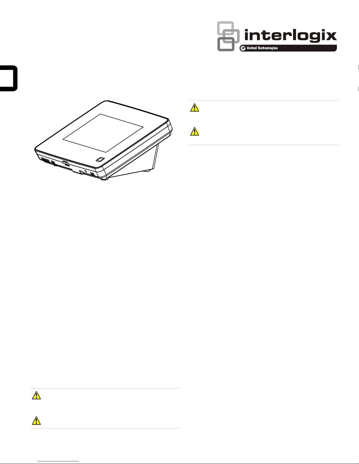
Simon 5" TouchScreen Installation Sheet
CAUTION: Use static electricity precautions when
handling electronic components.
CAUTION: Only the cable provided with the device can be
used to provide power.
Installation Guidelines
Use the following guidelines when adding this touch screen to
the Simon XT, XTi, or XTi-5 system:
Description
The Simon 5” TouchScreen model 60-924-RF-TS5 features a
color 5-inch LCD screen with a graphical user interface
designed to control basic functionality of the Simon XT (v1.3 or
later), Simon XTi, and Simon XTi-5 control panels. Up to four
touch screens can be learned (programmed) into each Simon
XT, XTi, or XTi-5 panel.
The touch screen provides a convenient option for the
following system operations:
• Arm the system (doors, windows, and motion sensors).
• Disarm the system.
• Activate a panic alarm to call the central monitoring station
in a nonmedical emergency.
• Check system status.
• Turn system controlled lights on or off (depending on your
system configuration).
• Lock and unlock system-controlled door locks (depending
on your system configuration).
• Hear voice feedback of the status of the Simon XT, XTi, or
XTi-5 control panel.
Safety information
IMPORTANT SAFETY INFORMATION. READ ENCLOSED
WARNINGS AND SAFETY INFORMATION.
• Power up and learn the touch screen into the panel and
verify its operation before mounting it to its permanent wall
or desktop location.
• The touch screen should be the last sensor programmed
(learned) into the panel. Doing this allows the panel’s
programming configuration to be properly transferred to
the touch screen.
• Program (learn) the touch screen into the panel as a
sensor Using group types 00, 01, 04, 05, 06, or 07.
• The touch screen will work best if mounted greater than
3 ft. (approximately 1 m) from the Simon panel.
• Avoid mounting the touch screen directly behind the
Simon XT, XTi, or XTi-5 panel on the opposite side of the
wall.
• Always do a sensor test before attaching the touch screen
to the wall.
Preparation
To begin
1. Separate the touch screen and the mounting base from
the preassembled desktop stand. Remove the desktop
stand by holding the touch screen unit with one hand and
prying the desktop stand at the removal tab marking until it
separates (Figure 1) with the other. Put the desktop stand
aside temporarily.
WARNING: CHOKING HAZARD. The product accessory
bag contains items that could be choking hazards. Please keep
away from small children.
WARNING: Disconnect panel power before servicing.
© 2018 UTC Fire & Security Americas Corporation, Inc. 1 / 6 P/N 466-5412 (EN) • REV A • ISS 15JAN18
Page 2
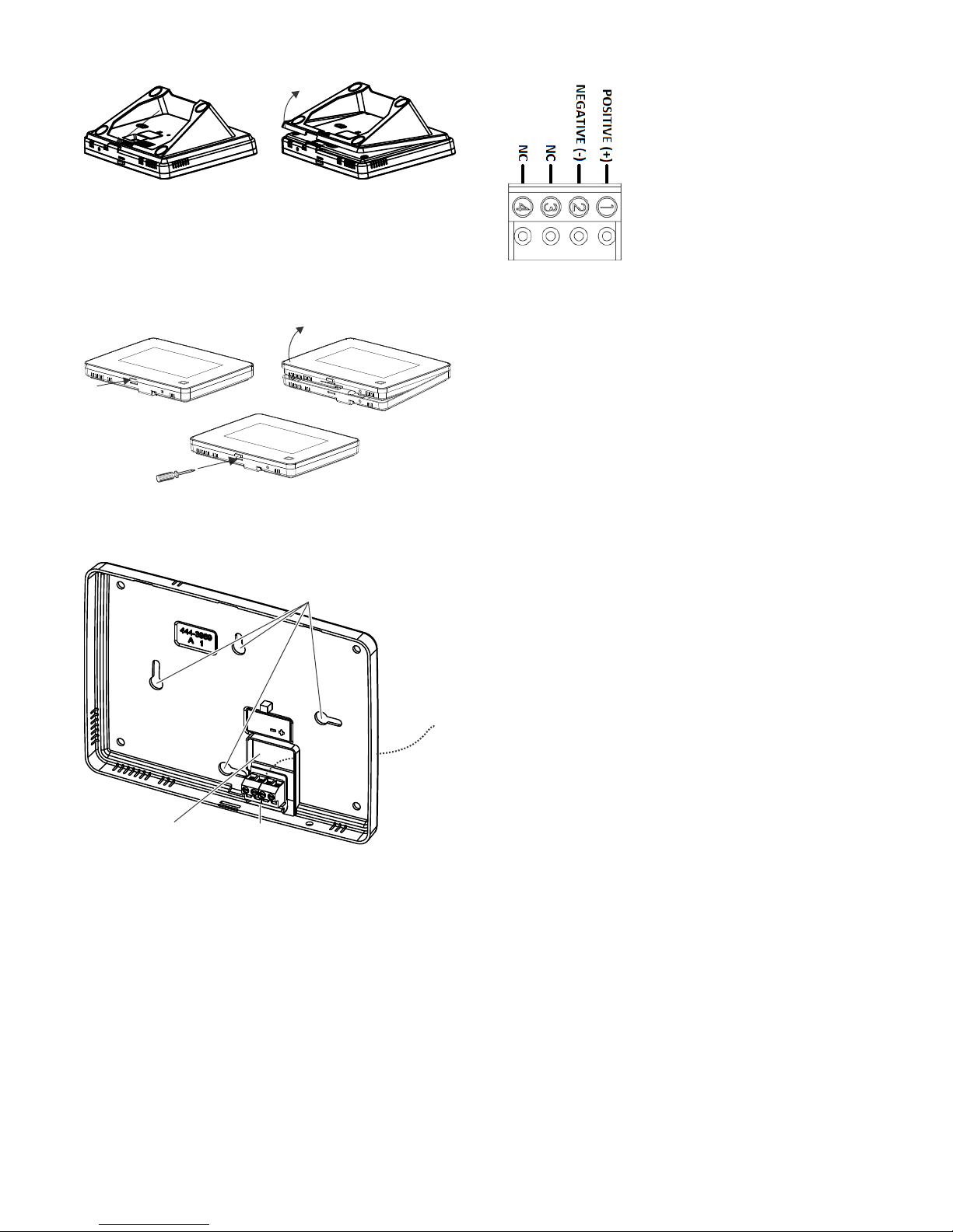
Opening
button
Terminal
block
Wires
Mounting
holes
Wire drop
opening
Figure 1: Desktop stand removal
2. Remove the touch screen from the mounting base
pressing the opening button on the bottom of the touch
screen (as shown in Figure 2). In case parts stick to each
other firmly, try to separate them by inserting a small
screwdriver into the opening slot beneath the protruding
opening button (Figure 2).
Figure 2: Opening slot
3. Feed the supplied power wire through the backside of the
wire drop in the mounting base (Figure 3).
Figure 3: Power Wire Routing in the Mounting Base
Figure 4: Power connector
5. Reattach the touchscreen to the mounting base plate.
Angle the top of the touch screen into the tab hooks on the
top of the mounting base and swing the bottom of the
touch screen into the lower part of the mounting base until
you hear an audible click.
6. Connect the spaded ends of the power supply wire to the
terminal to the terminals on the power supply. Note: The
dashed line/writing side of the wire to positive. Ensure
consistency by wiring the + to + and – to – as polarity must
be observed or touchscreen will not function. Plug in the
power, the touch screen will power up.
Learning
To program (learn) the touch screen into the Simon XT
panel:
4. Connect the wire to the power terminals as identified in
Figure 4, taking particular care to ensure the
marked/dashed wire attaches to the Positive lead and the
unmarked wire attaches to the Negative lead. Observe
polarity by ensuring the same wire at the touch screen
mounting base is connected to the corresponding positive
and negative lead on the power supply. Do not use
different or longer run cable than the supplied wiring as
the DC power supply may not support it and intermittent
power failures in the touch screen may occur due.
1. Press the down arrow button on the panel and scroll to
System Programming.
2. Press OK.
The panel displays Enter Code.
3. Enter the installer access code and press OK.
4. Scroll to Sensors and press OK.
5. When the panel displays Learn Sensor, press OK.
The panel blinks Trip Sensor nn (where nn is the next
available zone number). You can enter a different zone
number if desired.
6. On the touch screen:
A. Press the Settings button (gear icon at bottom right).
B. Press the Down arrow until the Clear and Enroll
button appears.
C. Press the Clear and Enroll button. The touch screen
should indicate it is waiting for enrollment.
7. On the panel, you can now program the group number
(00, 01, 04, 05, 06, or 07) and press OK.
8. On the panel, press the Up or Down arrow to select a
name for the touch screen and press OK. (Refer to the
Simon XT installation instructions for programming sensor
text.)
2 / 6 P/N 466-5412 (EN) • REV A • ISS 15JAN18
You can select something simple, such as “Touch Pad”, or
use additional descriptors, such as “Bedroom Touch Pad”.
Page 3

The touch screen will indicate enrollment success or
failure.
Note: During install mode, it is normal for the four blue
LEDs on the panel to blink as this indicates the panel is
updating the touch screen status. Do not leave program
mode if you have modified sensor information or are
downloading a company logo while the four blue arming
LEDs on the panel are blinking (this may disrupt
configuration).
9. To verify that the touch screen is programmed (learned),
press the Status button on the panel repeatedly to leave
system programming and return to normal panel
operation.
10. Press the Settings button on the touch screen and press
the Hear button.
The touch screen should announce the panel arming level
and status, such as Disarmed System Okay.
To program (learn) the touch screen into the Simon XTi
and XTi-5 panel:
1. On the Simon XTi panel, press the icon in the bottom
right corner of the touchscreen.
2. From the Status & Settings screen, press to scroll to
the Programming option and press ENTER.
3. Enter the dealer or installer code and press OK.
4. From the Programming screen, press SENSORS.
5. From the Sensors screen, press LEARN SENSORS. The
panel displays the Edit Sensor screen.
On the touch screen:
A. Press the Settings button (gear icon at bottom right).
B. Press the Down arrow until the Clear and Enroll
button appears.
C. Press the Clear and Enroll button. The touch screen
should indicate it is waiting for enrollment.
6. On the panel, you can now program the group number
(00, 01, 04, 05, 06, or 07) by pressing EDIT next to Sensor
Group.
7. On the panel, select a name for the touch screen by
pressing EDIT next to Sensor Name.
You can select something simple, such as “Touch Pad”, or
use additional descriptors, such as “Bedroom Touch Pad”.
The touch screen will indicate enrollment success or
failure.
Note: Do not leave program mode if you have modified
sensor information or are downloading a company logo
(this may disrupt configuration).
8. To verify that the touch screen is programmed (learned),
press the Close button on the panel repeatedly to leave
system programming and return to normal panel
operation.
9. Press the Settings button on the touch screen and press
the Listen button.
The touch screen should announce the panel arming level
and status, such as Disarmed System Okay.
Refer to your Simon XTi or XTi-5 panel documentation for
other programming options.
Note: If you would like this touch screen operation to be code
protected, you can enable this feature by following these steps:
1. Select the Settings menu.
2. Scroll to “Code Required Access” and select Yes.
With code required access, not all icons will be displayed.
Relocate the touch screen to permanent location
1. Unplug the touch screen from the wall.
2. Move the unit to its permanent location.
3. Plug the touch screen power supply into the wall.
Sensor test
The touch screen is sensitive to its orientation to the control
panel. For that reason, we recommend you test the touch
screen before it’s mounted in its permanent location.
To test the touch screen with the Simon XT (v1.4) panel:
In the Setting menu, press the Test button under RF Test. If
less than three bars appear see “Relocate the touch screen to
permanent location” above.
To test the touch screen with the Simon XT (v1.3) panel:
1. Make sure the panel is disarmed.
2. Press the down arrow button on the panel and scroll to
System Programming.
3. Press OK.
4. When the panel displays Enter Code, enter the
appropriate code and press OK.
5. Scroll until the panel displays Sensor Test, press OK to
start the sensor test.
The panel will prompt you to trip each sensor one at a
time.
6. To trip the touch screen, press the RF test button from the
settings screen.
You can follow the panel voice prompting to test the
sensors in any order. You should hear the panel beep the
number of packets received. The panel will also display
the number of packets received. If you do not hear 6 to 8
panel beeps, see “Relocate the touch screen to
permanent location” above.
To test the touch screen with the Simon XTi and XTi-5
panel:
1. Make sure the panel is disarmed.
P/N 466-5412 (EN) • REV A • ISS 15JAN18 3 / 6
Page 4

Wires
2. Access the System Tests screen through the Status &
Settings screen by pressing ENTER next to
PROGRAMMING.
3. Enter the access code and press OK.
4. Press SYSTEM TESTS.
5. Press SENSOR TEST.
6. All learned in sensors will be displayed on this screen.
Press to scroll through the pages).
7. To trip the touch screen, press the RF test button from the
settings screen.
You should hear the panel beep the number of packets
received. The panel will also display the number of
packets received. If you do not hear 6 to 8 panel beeps,
see “Relocate the touch screen to permanent location” on
page 3.
8. Press Close repeatedly to exit.
You should also perform the following to validate the touch
screen installation:
1. Arm the panel and verify that the panel and touch screen
indicate that the panel is armed.
2. Wait 10 minutes and verify that you do not get a “loss of
connection” message and that the RF icon is not red.
We recommend that you test the touch screen after all
programming is completed and whenever a touch screen
related problem occurs.
To verify communication between the panel and the touch
screen, exit programming mode and then press the System
Status icon on the touch screen. The touch screen should
announce the correct system status.
Note: If you cannot get the touch screen to trip, test a known
good touch screen at the same location. If the replacement
touch screen functions, contact UTC Fire & Security for repair
or replacement of the faulty touch screen.
Mounting
1. With touch screen operation verified and tested at the
permanent location; mount the touchscreen either on the
wall or on a surface with the supplied desktop stand.
Surface, desktop mounting
If the unit is to be wall mounted, skip to step 5.
2. Unplug power supply and feed it though the desk top
stand from front to back so that the power wire and supply
extends from the touch screen and mounting base,
through the desktop stand (Figure 5).
Figure 5: Power cable routing with desktop stand
3. Reattach the desktop stand to the mounting base and
touch screen.
4. Plug the power supply back into the wall. Ensure the outlet
is not controlled by a switch.
Wall mounting
If the unit is to be or has been installed on surface utilizing the
desktop stand, skip to the next section.
Note: Wall mounting uses only the mounting base; the desktop
stand is not used.
5. Separate the mounting base from the touch screen.
6. From the initial power up configuration, disconnect the
power cable Positive and Negative leads from the
mounting base. Disconnect the wire from the power
supply.
7. Hold the base on the wall at the desired mounting location
and mark the mounting holes and wire drop.
8. At the mounting hole locations, drill 3/16-inch holes into
the wall for plastic anchors.
9. At the wire drop opening, drill a 1/2-inch hole into the wall
for the power cable.
10. Push the two plastic anchors into the drilled holes and
tighten screws within a quarter-inch of the anchors.
11. Feed the power wiring through the backside of the wire
drop in the mounting base (see Figure 3 on page 2).
12. Hang the base using the screws, level the base, and
tighten the screws.
13. Run the power cabling behind or down the front of the wall
to the nearest power receptacle.
14. Reconnect the ends of the wire to the power terminals as
identified in Figure 4, taking particular care to ensure the
marked/dashed wire attaches to the Positive lead and the
unmarked wire attaches to the Negative lead.
15. Feed any extra wire back into wall. Wires should not
protrude outside of the wire drop opening.
16. Reattach the touch screen to the mounting base. Angle
the top of the touch screen into the tab hooks on the top of
the mounting base and swing the bottom of the touch
screen into the lower part of the mounting base until you
hear an audible click.
4 / 6 P/N 466-5412 (EN) • REV A • ISS 15JAN18
Page 5

Opening
button
Reset
button
17. Reconnect the spaded ends of the power supply wire to
the terminal to the terminals on the power supply. Note:
The dashed line/writing side of the wire indicates positive.
Ensure consistency by wiring the + to + and – to – as
polarity must be observed or touchscreen will not function.
Operation
Refer to Simon 5” TouchScreen Quick Operation Guide for
basic touch screen operation information. Refer to the panel
documentation for complete Simon XT, XTi, and XTi-5
programming and operation information.
Setting the clock
You can set the touch screen clock by setting the clock on the
Simon XT, XTi, or XTi-5 panel.
Battery Pack replacement
We recommend that you replace the backup battery pack
every 3-5 years. Only the part 60-924-BAT4SIMONTS5 can be
used as a battery pack replacement.
1. Remove the touch screen from the mounting plate by
depressing the button on the bottom of the touch screen.
Note: If AC power is lost and battery pack is not present or
depleted, the touch screen will not power up until AC power is
restored (even if a new battery pack is installed).
Reset button
The Reset button is located on the bottom right side of the
touch screen mounting plate (see Figure 7). To power cycle
the touch screen, use a toothpick to depress the recessed
Reset button. Note the reset has no impact on the Simon panel
or the overall state of the alarm system. The button simply
resets the only the touch screen to the same state
Note: Do not press the Reset button while in programming
mode.
Figure 7: Reset
2. Remove the five screws from the back cover of the touch
screen and separate the back cover off the front cover.
3. Disconnect the battery from the battery connector and
remove the battery as showing in Figure 6. Replace the
battery pack.
Avoid touching the touch screen face while you are replacing
the batteries.
Figure 6: Battery
Clear operation
If the Simon XT, XTi, or XTi-5 panel is connected to an online
service, some information (such as a dealer logo) can be
stored in the touch screen memory. To erase touch screen
memory and restore to factory default, simply relearn the touch
screen into the panel again. The learn in process begins by
clearing the touch screen memory. To keep memory clear,
learn the touch screen into a Simon XT, XTi, or XTi-5 panel
that has no online service supported.
Troubleshooting
• If your touch screen fails to power up, check the wiring to
ensure the connections are connect. Ensure the wires are
not crossed from Positive to Negative or vice versa.
• If your touch screen flickers, restarts or has intermittent
issues or does not seem to operate consistently, ensure
the power polarity from the transformer to the Positive and
Negative leads on the touch screen is correct. Also do not
use wire for power other than the cable supplied. Longer
cable may cause power delivery issues to the touch
screen.
P/N 466-5412 (EN) • REV A • ISS 15JAN18 5 / 6
• If your touch screen fails to enroll, go to the Simon panel,
delete that touch screen from the panel, and then repeat
the enroll procedure.
• If the touch screen chime does not announce the zone
name completely, it is likely due to the zone information
not being sent to the touch screen during installation. To
Page 6

Compatibility
Simon XT (version 1.3 and later),
Simon XTi, Simon XTi-5
Power
Input 100-120 VAC, 250 mA
Output 6 VDC, 1000 mA
Backup batteries
3.6 VDC, 600 mAh, NiMH
Backup time
6 h min.
Dimensions (W × H × D)
6.7 × 5.0 × 0.8 in. (170 × 127 × 20 mm)
Color
White
Operating environment:
Temperature
32 to 104°F (0 to +40°C)
Maximum relative humidity
85% noncondensing
FCC
This equipment has been tested and found to
comply with the limits for a Class B digital device,
pursuant to Part 15 of the FCC Rules. These
limits are designed to provide reasonable
protection against harmful interference in a
residential installation.
This equipment generates, uses, and can radiate
radio frequency energy and, if not installed and
used in accordance with the instructions, may
cause harmful interference to radio
communications. However, there is no guarantee
that interference will not occur in a particular
installation.
If this equipment does cause harmful interference
to radio or television reception, which can be
determined by turning the equipment off and on,
the user is encouraged to try to correct the
interference by one or more of the following
measures:
• Reorient or relocate the receiving antenna.
• Increase the separation between the
equipment and receiver.
• Connect the equipment into an outlet on a
circuit different from that to which the
receiver is connected.
• Consult the dealer or an experienced
radio/TV technician for help.
Changes or modifications not expressly approved
by UTC Fire and Security could void the user’s
authority to operate the equipment.
This Class B digital apparatus complies with
Canadian ICES-003.
Warnings and
Disclaimers
These products are intended for sale to, and
installation by, an experienced security
professional. UTC Fire & Security cannot provide
any assurance that any person or entity buying its
products, including any “authorized dealer,” is
properly trained or experienced to correctly install
security related products.
For more information on product warnings, refer
to firesecurityproducts.com/policy/productwarning/ or scan the code.
correct the problem, delete the touch screen and relearn
the touch screen again.
• Red text on the Door Lock page indicates an open door or
a door that is not monitored.
• If the sensors and the At-a-Glance icons state on the main
screen are not synchronized or operating as expected to
provide building status, use the following as a guideline
when naming sensors in the Simon panel:
• Sensor names must have the word “window” or “door”
from the text library to interact with the touch screen Doors
and Windows icons on the Main screen.
• The Motion icon is controlled by sensors that are
programmed into the following groups: 15, 17, 18, 20, 28,
and 32.
• The Property icon is controlled by the following sensors:
- All sensors learned into Group 43.
- Sensors that are not named “window” or “door”.
- Sensors not learned into the Motion groups.
- Sensors that are named keyfob or keychain.
Specifications
Regulatory information
6 / 6 P/N 466-5412 (EN) • REV A • ISS 15JAN18
Contact information
www.utcfireandsecurity.com or www.interlogix.com
For customer support, see www.interlogix.com/customer-
support
© 2018 UTC Fire & Security Americas Corporation, Inc.
Interlogix is part of UTC Climate Controls & Security, a unit of
United Technologies Corporation. All rights reserved.
 Loading...