

Page 1
5845-ID
g
Description
The 5845-ID (Figure 1) is an addressable glassbreak
device that interfaces with the PinPoint® system. The
system provides flexible and reliable two-way
communication between the device and the controller.
This glassbreak device is based on ShatterPro® II
technology and uses patented Pattern Recognition
Technology.
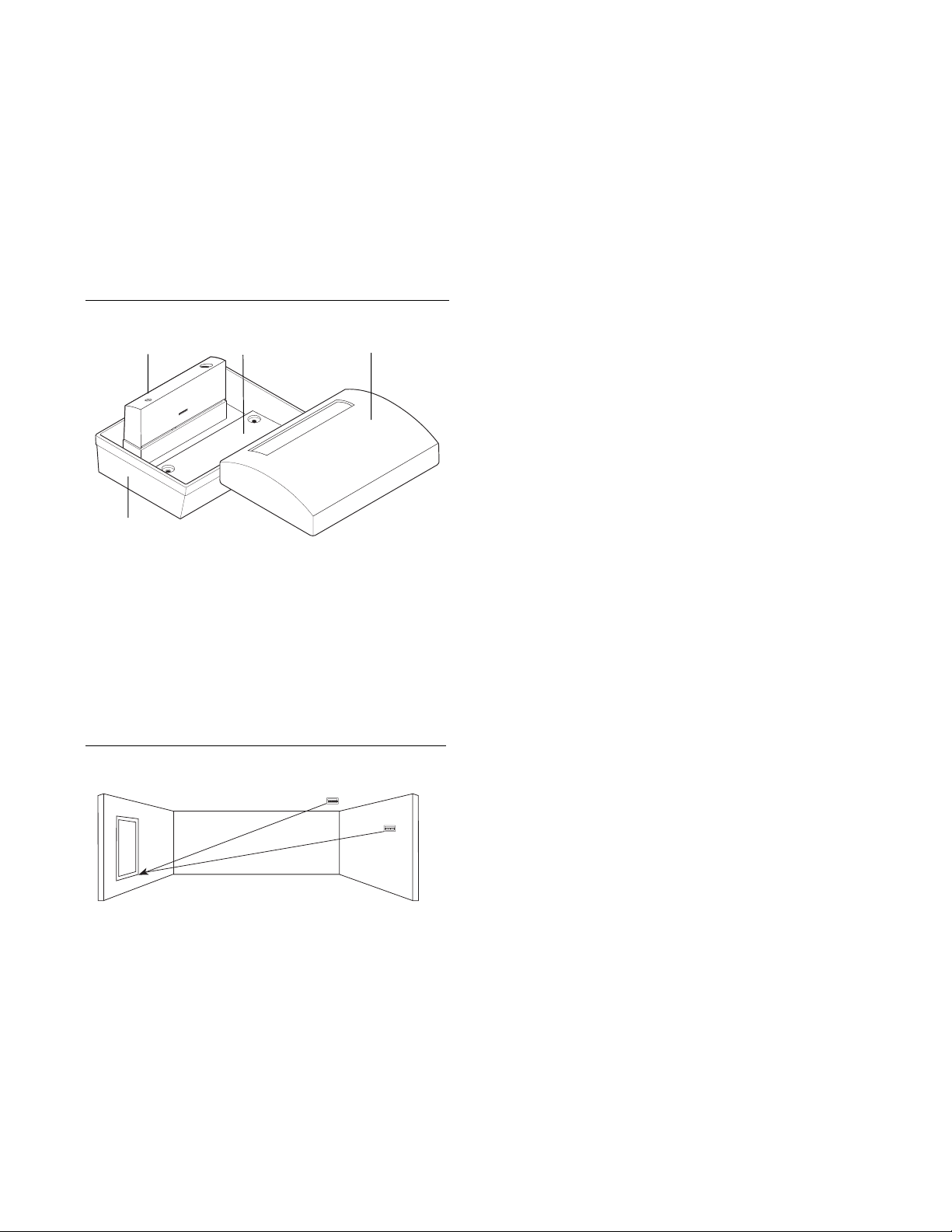
Figure 1. Exploded view
Sensor module
Base
Range
The unit is omni-directional, providing 360° coverage.
Coverage is measured from the unit to the most distant
point on the glass (Figure 2).
Minimum 3.3 feet (1 m) from the glass
Maximum 20 feet (6 m) for plate, tempered,
laminated, and wired glass; 12 feet (3.7
m) for armor-plated glass
Figure 2. Maximum range
20 ft. (6 m)
20 ft. (6 m)
installation instructions
For best detection, avoid installing in:
• Rooms with lined, insulating, or sound deadening
drapes
• Rooms with closed, inside wooden window shutters
• Corners of a room
• Glass airlocks and glass vestibule areas
For best false alarm immunity:
• Install the unit as a perimeter zone which is armed
only when the perimeter doors and windows are
armed. Avoid installing the unit as a 24-hour zone,
where the unit will be armed even when the room is in
use.
• Do not install in humid rooms such as small utility and
bathrooms. The unit is not hermetically sealed and
excess moisture on the circuit board can eventually
cause a short and a false alarm.
• Do not use where white noise, such as air compressor
noise, is present. A blast of compressed air may cause
a false alarm.
• A void rooms smaller than 10 by 10 feet (3 by 3 m) and
rooms with multiple noise sources such as noisy
kitchens, stairwells, residential garages, and other
small accoustically live rooms.
Mounting location
For best false alarm immunity the unit should be located at
least 4 feet (1.2 m) away from noise sources (televisions,
speakers, sinks, doors, etc.). The unit must always be in
direct line of sight of all windows to be protected. There is
no front or back, up or down, orientation of the sensor
required.
Wall mount
Since the sound of breaking glass travels directionally out
from the broken window , the best location for mounting
the unit is on the opposite wall, within the unit’s range
and line of sight.
Recommended glass size
Minimum 1 by 2 feet (0.3 by 0.6 m)
Glass thickness:
Plate 3/32 to 1/4 inch (2 to 6 mm)
T empered 1/8 to 1/4 inch (3 to 6 mm)
Wired 1/4 inch (6 mm)
Laminated 1/8 to 1/4 inch (3 to 6 mm)
Ceiling mount
Mount the unit on any type of ceiling in a location which
is in direct line of sight of the windows to be protected.
However, since sound travels directionally out from the
broken window , a position 6 to 10 feet (2 to 3 m) into the
room provides optimal detection.
Page 2
2 5845-ID
SON APEMS
Installation Instruction
Installation
See Figure 3 and do the following steps to install the unit.
1 . Run the PinPoint system wiring to the unit location.
2. Open the unit by gently inserting a screwdriver in the
hidden opening notches that are located under the lid
in the middle of the long side of the unit.
CAUTION You must be free of all static electricity
before handling sensor circuit boards.
Touch a grounded, bare metal surface
before touching ciruit boards or wear a
grounding strap.
3 . Set the PinPoint address DIP switches. Devices are
shipped with DIP switches set to 255. This is an
invalid address. The device will not communicate with
the controller until a valid address has been set.
Refer to the controller's manual to determine the
correct address setting for each unit.
4. Remove the appropriate wiring knockouts and use the
mounting screws to remove the mounting knockouts.
5 . Pull the PinPoint wiring through the wiring knockout
holes.
6. Attach the base to the mounting surface with two
screws through the mounting knockout holes. Use
wall anchors if necessary .
7 . Strip 1/4 inch (6.4 mm) of insulation from each
PinPoint wire. Connect the wiring to the appropriate
screw terminals and tighten the screws.
8 . Replace the lid on the unit.
9. Test the unit when the PinPoint system is completely
installed and the control panel is powered.
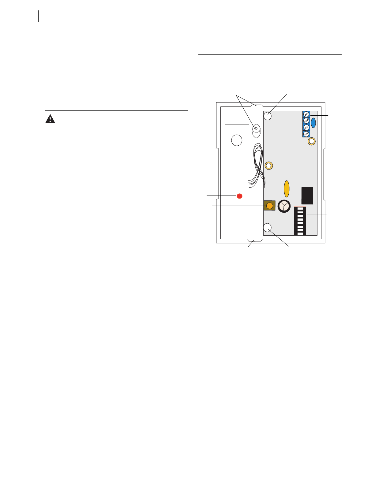
Figure 3. Base and circuit board
PinPoint wiring
knockout
Opening
notch
LED
Tamper
switch
PinPoint wiring knockout
Mounting knockout
+ - + -
IN
OUT
ON APEM
Mounting knockout
1 2 3 4 5 6 7 8
PinPoint
terminal
block
Opening
notch
DIP
switches
Page 3

3
Testing
The Pattern Recognition Technology of the unit ignores
most false alarm sounds, including glassbreak testers. In
order to test the unit, a test mode is used. With the unit in
test mode, processing of the glassbreak pattern in the
upper and lower frequencies is disabled. The unit is then
listening only for the mid-range frequencies, which the
5709C tester reproduces. It’s the mid-range frequencies
that determine unit range.
1 . Lift the unit's lid off and put it back on to activate the
LED for the walk test.
2. Use the 5709C hand-held tester to set the unit into
test mode. The 5709C tester has a different setting for
each type of glass. (The tester should always be set
for tempered or laminated glass unless the installer is
certain that all the glass to be protected is plate
glass.) Hold the tester speaker directly on top of the
unit and activate the tester. The unit will alarm then
go into test mode for one minute. When in test mode,
the LED on the unit will blink continuously . Extend
the test mode time by firing the tester at the unit at
least once a minute. In normal mode the LED does
not blink unless it hears a loud sound and the unit
will not trip to the tester, unless the tester is held next
to the unit.
3. Holding the tester near the surface of the glass, aim
the tester at the unit and hold down the test button
(Figure 4). If drapes or blinds are present, test with
the tester behind the closed drapes or blinds (do not
use with heavy or lined drapes).
When the LED on the unit goes solid momentarily
while the tester is triggered, the glass is within
detection range.
4 . If the LED does not go solid, but simply continues
blinking, reposition the unit closer to the protected
windows and retest. Additional units may be required
to achieve adequate coverage. It is very rare that the
unit will not activate within its stated range of
coverage. Double check adequate battery strength in
the tester. A new tester battery may be needed to
restore range.
The unit will automatically change from test mode to
normal mode approximately one minute after it last
hears the tester. LED feedback will time out in three
minutes.
Figure 4. Testing the unit
Do not exceed the rated range of the sensor , regardless of
what the tester shows. Room acoustics can artificially
extend the range of a glassbreak sensor. The specified
range of the unit has been established for worst-case
conditions. While the unit will likely function at additional
range, it may miss a minimum output break, or room
acoustics may be changed at some future time, bringing
the unit range back into normal 20 foot (6 m) conditions.
Proper testing
The unit is designed to detect the breaking of framed
glass mounted in an outside wall. Testing the sensor with
unframed glass, broken bottles, etc., may not trip the unit.
The unit typically does not trip to glass breaking in the
middle of the room and may not consistently detect cracks
in glass, or bullets which break through the glass.
Glassbreak sensors should always be backed up by
interior protection.
Hand clap test
To verify visually that there is power to the unit and that
the microphone and circuit board are functioning, clap
your hands loudly under the unit (in normal mode). The
LED will blink twice, but the unit will not trip.
Maintenance
When installed and used properly, this unit provides
years of service with minimal maintenance. You should
test the unit annually to ensure proper operation.
Clean the cover with a damp (water) cloth as needed to
keep it free of dust and dirt. Always test the unit after
cleaning.
Page 4

4 5845-ID
Installation Instruction
Specifications
Housing material Flame retardant ABS
Operating voltage 8 to 27V, (as supplied by
the PinPoint bus)
Current draw 250µA typical average
3 mA with LED momentarily on
Microphone Omni-directional electret
Operating temperature 14 to 120°F (-10 to 50°C)
Relative humidity 10 to 90% non-condensing
Maximum line length 10,000 ft. (3 km)
Dimensions:
Width 3.13 in. (8.0 cm)
Depth 1.70 in. (4.3 cm)
Height 4.24 in. (10.8 cm)
Color White
Listing FCC, CE
FCC compliance
This device complies with Part 15 of the FCC rules. Operation is
subject to the following two conditions:
1. This device may not cause harmful interference.
2. This device must accept any interference received,
including interference that may cause undesired operation.
Product ordering
Product Description
5845-ID Addressable ShatterPro® II
glassbreak for use with the
PinPoint bus.
5709C Glassbreak tester
12345 SW Leveton Drive
GE Security
Tualatin, OR 97062
503-692-4052
USA & Canada: 800-547-2556
Tech Support: 800-648-7424
www.ge-security.com
1036047C / September 2004
 Loading...