

Page 1

Wireless ShatterPro Acoustic Sensor Installation
Instructions
directionally out from a broken window, a position 8 ft. (2.4 m)
Introduction
This is the Wireless ShatterPro Acoustic Sensor
Installation Instructions for models 584503-W (3 V) and
584509-W (9 V). The sensor is designed to detect breaking
glass from framed windows in the perimeter of a building.
Install the sensor on a perimeter loop armed whenever the
door and window contacts are armed. Avoid 24-hour loop
applications where the sensor is armed all day and all night.
The false-alarm technology will be pushed to its limit in a 24hour loop.
The sens or’s fals e-alarm immunity is best in rooms with only
moderate noise. Some sounds can duplicate the points on the
glassbreak pattern the sensor detects.
The sensor may not consistently detect cracks in glass, or
bullets which break through the glass. Glassbreak sensors
should always be complemented with interior protection.
Connect the sensor to a UL listed control panel, or a power
supply that provides at least four hours of standby power.
Use a 9-volt battery if longer life is needed in the 584509-W.
Mounting location
The sensor must always be in direct line of sight of all windows
to be protected. The sensor cannot consistently detect glass
breaking around corners or in other rooms. There is no
required front, back, up or down orientation.
into the room provides better detection.
Use the following guidelines to determine the best mounting
location:
• Mount the sensor at least 3.3 ft. (1 m) from the windows
being protected and at least 4 ft. (1.2 m) from noise
sources such as TVs, speakers, sinks, and doors.
• Mount the sensor in the direct line of sight of the glas s to
be protected.
• Avoid rooms smaller than 10 x 10 ft. (3m x 3m).
• Avoid locations where lined, insulating, or sound-
deadening drapes or clos ed wooden shutters are used.
• Mount the sensor in a suitable environment: temperature
between 0 and 120°F (-18 and 50°C); and humidity
between 10 and 90% noncondensing. Do not install the
sensor in humid rooms. Excess moisture on the circuit
board can eventually cause a short and a false alarm.
• Mount the sensor on a stable surface up to 25 ft. (7.6 m)
from the farthest point on the glass surface.
• Avoid locations that expose the sensor to possible false-
alarm sources such as:
• glass airlocks and vestibule areas;
• kitchens;
• corner mounting;
• residential car garages;
• small utility rooms;
• stairwells;
• bathrooms; and
• small acoustically live rooms.
Wall mount
The best wall-mount location is on the opposite wall, assuming
the glass to be protected is within the sensor’s range and line
of sight. The adjoining wall can also be used.
Ceiling mount
Mount the sensor in a location that is in direct line of sight of
the glass to be protected. However, since sound travels
P/N 11089 • REV H • OCT12 1
Coverage range
The sensor is omni-directional, providing 360° coverage.
Coverage is measured from the sensor to the point on the
glass farthest from the sensor. The sensor can be mounted as
close as 3.3 ft. (1 m) from the glass. The maximum range
depends on the type of glass being protected:
Armor-coated glass
Mount sensor no more than 12 ft. (3.6 m) from the glass.
Page 2
Plate, tempered, laminated, and wired glass
Sensor module
Transmitter
Base
Sensor module
Transmitter
Bracket
Sensor module
Sensor module
Catch
Base
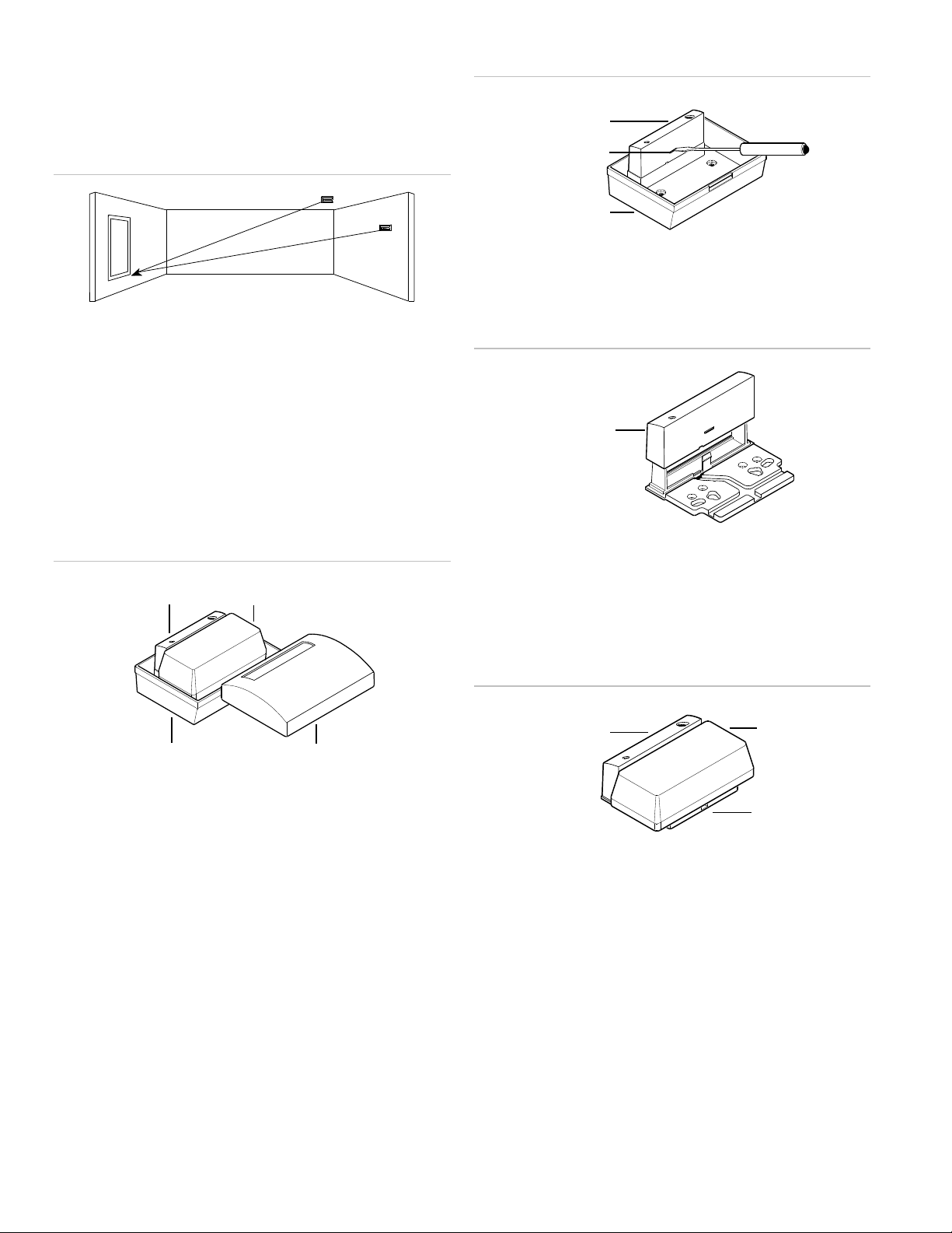
25 ft. (7.6 m)
25 ft. (7.6 m)
Mounted on the ceiling or the opposite or adjoining wall,
(Figure 1 below) maximum range is 25 ft. (7.6 m).
Figure 1: Maximum coverage range
Installation
The sensor has two mounting options.
Sensor base housing
You can place the wireless trans mitter ins ide the sensor’s base
housing (Figure 2 below). For some large transmitters, it will
be necessary to remove the transmitter board from its housing.
Figure 2: Sensor base housing
Figure 3: Removing the sensor module
2. Snap the sensor module unto the bracket (Figure 4
below).
Figure 4: Snapping the sensor module onto the bracket
3. Run the wires to the transmitter and attach the transmitter
to the bracket (Figure 5 below). Use the punched doublestick tape provided to hold the wire in the bracket’s wire
channel, and to hold the transmitter to the bracket.
Transmitter bracket
For large transmitters that do not fit into the sensor base, or for
a smaller appearance with a standard size transmitter, use the
transmitter bracket.
To mount the sensor on the transmitter bracket, do the
following:
1. To remove the sensor module from the base, depress the
catch in the center of the sensor module (Figure 3 below)
and rock the module up off the posts.
Figure 5: Attaching the transmitter to the bracket
4. Mount the sensor/transmitter/bracket assembly. If the
transmitter’s mounting holes don’t fit the bracket’s hole
pattern, you will have to mount the bracket to the wall or
ceiling before attaching the transmitter.
Wiring
All wiring must conform to the National Electric Code (NEC)
and/or local codes having jurisdiction.
2 Wireless ShatterPro Acoustic Sensor Installation Instructions
Page 3

584503-W Wiring
UTC Fire & Security
3.5 V programmable
Transmitter
584503-W
UTC Fire & Security
3.5 V learn mode
Transmitter
584503-W
UTC Fire & Security
3.5 V System VI
Transmitter
564503-W
Black
Black
Black
Red
Green
(NL)
Red
Green
(NL)
Red
Green
Black
564509-W
Ademco
5716
transmitter
Red
Green
(NL)
Black
Red
White
Green
Figure 6 below shows the 584503-W wiring (shares transmitter
battery). The wires are:
Red - To battery +.
Black - To battery -.
White - Normally open (closes on alarm to battery - ).
Green - Normally closed (to battery - ).
Figure 6: 584503-W wiring
Figure 8: 584503-W connections to the UTC Fire & Security 5816
transmitter
Figure 7 below shows the 584503-W connections to the
Ademco 5816 transmitter.
Figure 7: 584503-W connections to the Ademco 5816 transmitter
Figure 8 below shows the 584503-W connections to UTC Fire
& Security transmitters.
To connect the 583403-W to the transmitter, do the following:
1. Program the learn mode transmitter into the MCA.
2. Connect the sensor to the transmitter as shown in Figure 8
above.
3. Solder the red lead to the positive battery terminal on the
underside of the circuit board.
4. Put the cover on the transmitter and put it back into the
base. Snap the sensor cover in place.
5. Test with the 5709C tes ter. (See “Testing” on page 4.)
584509-W Wiring
Figure 9 on page 4 shows the 584509-W wiring (shares
transmitter battery). The wires are:
Red - To battery +.
Black - To battery -.
White - Normally high.
Green - Normally low.
Wireless ShatterPro Acoustic Sensor Installation Instructions 3
Page 4

Figure 9: 584509-W wiring
Black
Red
White
Ademco
5716
transmitter
Green
564509-W
Black
Red
Green
(NL)
584509-W
AT&T transmitter
Black
White
(NH)
Red
Honeywell 10-6506 (T-8803) transmitter
584509-W
Black
Green (NL)
GND
Red
Figure 10 below shows the 584509-W connections to the
Ademco 5716 transmitter.
Figure 10: 584509-W connections to the Ademco 5716
Figure 12 below shows the 584509-W connections to the
AT&T transmitter.
Figure 12: 584509-W connections to the AT&T transmitter
To connect the 584509-W to the AT&T transmitter, do the
following:
1. Splice the white wire from the sensor to the green wire
from the transmitter.
2. Connect the black wire from the sensor to the battery -.
To connect the 584509-W to the Ademco 5716 transmitter, do
the following:
1. Remove the battery.
2. On SW3, set switch 6 to Off (down). On SW4, set switch 1
to ON (up). Do not use a magnet.
3. Connect loop wires (green).
4. Connect 9-V battery terminals and install the battery
observing polarity.
Figure 11 below shows the 584509-W connections to the
Honeywell 10-6506 (T-8803) transmitter.
Figure 11: 584509-W connections to the 10-6506 transmitter
3. Connect the red wire from the sensor to the battery +.
4. On the 12-position DIP switch, set switch 6 to OFF for CL.
Set switch 7 to ON for PIR or glassbreak.
If you use this transmitter inside the back box, the circuit board
must be removed from the housing. You can secure it with the
double-stick tape provided. For the most secure connections, it
is better to solder the battery connector terminals instead of
using the buddy-up clips.
Testing
The sensor is designed to detect the breaking of framed glass
mounted in an outside wall. Testing the sensor with unframed
lass, broken bottles, etc., may not trip the sensor. The sensor
typically does not trip to glass breaking in the middle of the
room.
The Pattern Recognition Technology of the sensor ignores
most false alarm sounds, including glassbreak testers. To test
the sensor, use test mode. Test mode disables glassbreak
pattern processing in upper and lower frequencies. The sensor
is then listening only for the mid-range frequencies that the
UTC Fire & Security 5709C hand-held tester reproduces. It’s
the mid-range frequencies that determines sensor range.
4 Wireless ShatterPro Acoustic Sensor Installation Instructions
Page 5

Test mode
To put the sensor in test mode, do the following:
1. Use the 5709C handheld tester to put the sensor into test
mode. Set the tester to tempered glass and hold the tester
on top of the sensor.
2. Activate the tester. The sensor will alarm, then go into test
mode for one minute. In test mode, the LED will blink
continuously. To extend test time, fire the tester at the
sensor at least once a minute.
Sensor test
The sensor must be in test mode (blinking). To test the sensor,
do the following:
1. The tester has a different setting for each type of glass.
Set the tester for tempered or laminated glass unless you
are certain that all the glass to be protected is plate glass.
2. Hold the tester near the surface of the glass to be
protected and aim the speaker at the sensor. Be sure the
tester is at the point on the glass farthest from the
detector. If closed drapes or curtains are present, hold the
tester behind them (Figure 13 below).
Room acoustics can artificially extend the range of a
glassbreak sensor. The specified range of the sensor has been
established for worst-case conditions. While the sensor will
likely function at additional range, it may miss a minimum
output break, or room acoustics may change at some future
time, bringing the sensor range back into normal 20 ft. (6 m)
conditions. Do not exceed the rated range of the sensor,
regardless of what the tester shows.
Hand clap test
You can check the sensor while in normal mode, simply by
clapping your hands loudly under the sensor. The LED will
blink twice, but the sensor will not trip. This verifies visually that
there is power to the sensor, and that the microphone and
circuit board are functioning.
The hand clap activation is only momentary, so there is no
appreciable effect on battery life.
To disable this custom test function, remove the circuit board
from the housing and clip one of the wires on the LED. The
LED will no longer be operational, but the sensor can still be
tested using the transmitter and the control panel.
Maintenance
Figure 13: Testing behind curtains
3. Press the test button on the tester. The LED on the sensor
should stay on for 4 seconds to indicate the glass is within
detection range of the sensor. If the LED does not stay on
for 4 seconds, move the sensor and retest.
If the sensor will not activate within its stated range of
coverage, check for battery strength in the tester. A new tester
battery will likely restore range. You may need to use
additional sensors to achieve adequate coverage.
The sensor will automatically change from test mode to normal
mode approximately one minute after it last hears the tester. In
normal mode the LED does not blink unless it hears a loud
sound. In normal mode, the sensor will not trip to the tester,
unless the tester is held next to the sensor. Each time the
sensor alarms, it also goes into test mode for one minute.
When installed and used properly, the sensor provides years of
service with minimal maintenance. You should test the sensor
annually to ensure proper operation.
Clean the cover with a damp (water) cloth as needed to keep it
free of dust and dirt. Always test the sensor after cleaning it.
Wireless ShatterPro Acoustic Sensor Installation Instructions 5
Page 6

Specifications
Operational voltage
584503-W
584509-W
2.8 to 4.5 VDC
6 to 16 VDC
Current draw
584503-W
584509-W
17uA typical average
23 uA typical average, 5 mA w ith LED
momentarily on
Alarm duration
Four seconds
Output
584503-W
584509-W
Normally closed output and normally open
output with open drain MOSFETs; 700 Ohm
max. closed resistance; 10 Mohm min. open
resistance. Output voltage must be less than
or equal to supplied battery voltage
Normally low output with NPN transistor and
10M pull-up resistor and normally high output
with PNP transistor to power + 16 VDC max.
output voltage
RF immunity
20 V/m, 1 MHz to 1000M Hz
Microphone
Omnidirectional electret
Recommended glass
thickness
Plate
Tempered
Wired
Laminated
3/32 to 1/4 in. (2.4 to 6.4 mm)
1/8 to 1/4 in. (3.2 to 6.4 mm)
1/4 in. (6.4 mm)
1/8 to 1/4 in. (3.2 to 6.4 mm)
Operating temperature
14 to 120°F (-10 to 50°C)
Dimensions
4.25 x 3.13 x 1.70 in (108 x 80 x 43 mm)
Housing material
Flame-retardant ABS
Color
White
Wiring
22 AWG UL stye 1061, CSA T2, color-coded
wire, passes VW-1 flame test
Note: The 584503-W typically w orks down to 2.1 VDC and the
584509-W typically w orks down to 3.0 VDC, w hich allows most
transmitters to send low battery trouble alarms.
Product
Description
584503-W
Wireless ShatterPro, 3-V model with optional bracket
584509-W
Wireless ShatterPro, 9-V model with optional bracket
Accessories
5709C-W
Glassbreak hand-held tester, white
FCC compliance
This equipment has been tested and found to comply with the
limits for a Class B digital device, pursuant to Part 15 of the
FCC rules. These limits are designed to provide reasonable
protection against harmful interference in a residential
installation. This equipment generates, uses, and can radiate
radio frequency energy and, if not installed and used in
accordance with the instructions may cause harmful
interference to radio communications. There is no guarantee
that interference will not occur in a particular installation. If this
equipment does cause harmful interference to radio or
television reception, which can be determined by turning the
equipment on and off, the user is encouraged to try to correct
the interference by one or more of the following measures:
• Reorient or relocate the receiving antenna.
• Increase the separation between the equipment and
receiver.
• Connect the equipment into an outlet on a circuit different
from the one where the receiver is connected.
• Consult the dealer or an experienced radio/TV technician
for help.
Under FCC rules, Part 15 for Class B digital devices, operation
is subject to the following conditions:
1. This device may not cause harmful interference.
2. This device must accept any interference received,
including interference that may cause undesired operation.
Changes or modifications not expressly approved by the party
responsible for compliance could void the us er’s authority to
operate the equipment.
Product ordering
Contact information
www.utcfireandsecurity.com or www.interlogix.com
6 Wireless ShatterPro Acoustic Sensor Installation Instructions
For customer support, see www.interlogix.com/customer-
support
© 2012 UTC Fire & Security Americas Corporation, Inc.
Interlogix is part of UTC Climate Controls & Security, a unit of
United Technologies Corporation. All rights reserved.
 Loading...