

Page 1
Acoustic Glassbreak
C
S
Detector
5812-RND
Installation Instructions
Description
The 5812-RND is an acoustic glassbreak detector designed
to detect breaking glass from framed windows in the
perimeter of a building. The detector is mounted in the
building interior and uses a power supply from a 12VDC
control panel. The detector is available in a low-profile
round housing.
Features
The detector provides the following features:
• Range - 5 to 25 feet (1.5 to 7.6 m)
• Alarm memory - After an alarm and until power is
cycled, the alarm memory can be checked with the handclap test.
• LED indicator - Red LED provides detector test and
status indication.
• Tamper resistant - Provides a screw that secures the
cover to the base to prevent tampering.
• Hand-clap test - In addition to a test mode, you can
confirm the operation of the microphone by clapping
your hands.
What You Will Need
You need the following tools and parts to install the
detector:
• 5812-RND detector including screw to secure the cover
to the base
• Screws and wall anchors
• Flat-blade screwdriver
• Phillips screwdriver
• Sentrol 5709C hand-held tester
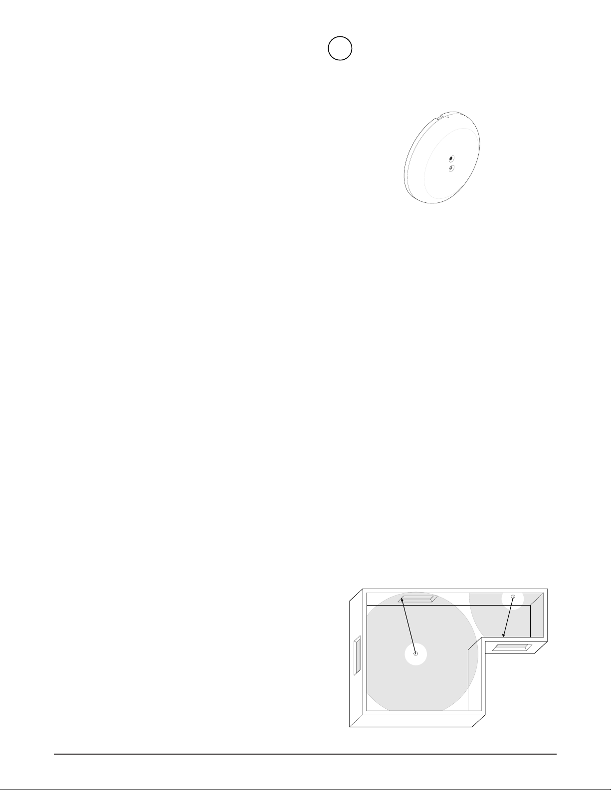
Selecting a Location for the
Detector
The detector can be mounted on ceilings or on walls
opposite or adjacent to the window to be protected. See
Figure 2.
Use the following guidelines to determine the best location
to install the detector.
U
¤
L
U
LISTED
Figure 1. 5812-RND
• Avoid locations where lined, insulating, or sound
deadening drapes are used.
• Mount 12 inches (30.5 cm) away from wall corners.
• Avoid locations where interior closed wooden
shutters are used.
• Locate in a suitable envionment as follows:
- T emperature between 32° and 122°F (0° and 50°C)
- Humidity between 10 and 90% non-condensing
• Mount the detector on a stable surface up to 25 feet
(7.6 m) from the farthest point on the glass surface.
See Figure 2.
• Avoid locations that expose the detector to possible
false alarm sources such as:
- Glass airlocks and vestibule areas
- Kitchens
- Residential car garages
- Small utility rooms
- Stairwells
- Bathrooms
- Small acoustically live rooms
- Air vents
Wall mount
25’ (7.6m)
max.
Ceiling mount
25’ (7.6m)
max.
• Mount at least 5 feet (1.5 m) from glass windows
being protected.
• Windows must be at least 12 x 24 inches
(30.5 x 61 cm) square.
5812-RND Acoustic Glassbreak Detector
Figure 2. Mounting Locations
1
Page 2
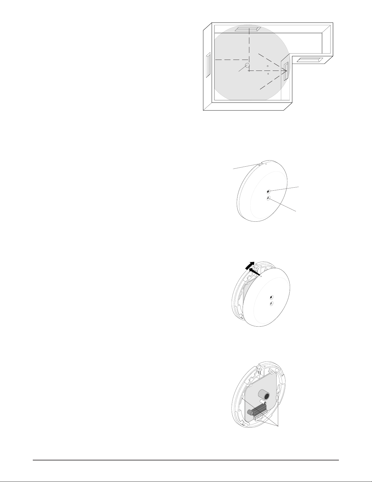
Selecting the Best Location for
Multiple Window Coverage
The detector has a 360degree coverage pattern that can be
used to cover several windows in a single room as follows:
CeilingCeiling
Ceiling
CeilingCeiling
mountmount
mount
mountmount
• Draw an imaginary line from the center of each window
to be covered in towards the center of the room.
• Mount the detector as close to where the lines intersect
as possible. See Figure 3.
• Do not mount the detector at more than a 60 degree
angle from the center of any window to be protected.
See Figure 3.
Installing the Detector
All wiring must conform to the National Electric Code
(NEC) and/or local codes having jursidiction.
Important !Important !
Important !
Important !Important !
If you are unsure about a location, connect a 9V
battery to the detector and test it before
permanently mounting. See T esting the Detector.
Use the following steps to install the detector:
1. Run the security system wiring to the detector location.
2. To remove the front cover, press the release tab on the
lip of the base, twist the cover counter clockwise, and
lift off. See Figure 4.
3. Remove the appropriate wiring and mounting
knockout holes from the base. See Figure 6.
4. Pull the wires through the knockout holes and use two
screws to attach the base to the surface. Use wall
anchors if necessary.
5. Strip 1/4 inch of insulation from each wire.
6. Connect the system wires to the appropriate screw
terminals on the base and tighten the screws. See
Figure 7.
7. To replace the cover, line up the tabs on the base with
the corresponding tabs on the cover, press together
and turn clockwise until the cover snaps firmly into
place. See Figure 5.
8. Apply power. The red LED should flash once.
9. Test the detector. See Testing the Detector.
Detector
Figure 3. Multiple Window Coverage
Release tab
Figure 4. Housing Parts
Figure 5. Attaching the Cover
60 max.
60 max.
Microphone
LED
Knockouts
Figure 6. Detector Knockout Locations
2
5812-RND Acoustic Glassbreak Detector
Page 3

• Single
• Continuous
Plate •
Tempered •
Laminated •
Battery LED
Battery is OK if LED
stays on during test
5709C
Shatter Series Tester
Use for testing:
ShatterPro
Shatterbox
Shatterbox II
ShatterSwitch
SENTROL
1” (2.5cm)
GND +12V N.C. COM
Figure 7. Wiring Terminals
Hold the tester so that the
speaker is within 1” (2.5cm) of
the detector microphone.
Testing the DetectorTesting the Detector
Testing the Detector
Testing the DetectorTesting the Detector
To verify detector range and operation, you need the
Sentrol 5709C hand-held tester .
Use the following steps to test the detector:
1. Set the tester to the appropriate glass-type setting.
Use the tempered setting if you are unsure about the
glasstype.
2. Put the detector in test mode as follows:
- Hold the tester 1” from the detector. See Figure 8.
- Activate the tester.
The LED on the detector lights for 4 seconds and then
starts flashing to indicate the detector is in test mode.
The relay opens for 4 seconds, then returns to
standby.
3. Hold the tester near the surface of the glass to be protected and aim the speaker at the detector. Be sure the
tester is at the point on the glass farthest from the
detector. If closed drapes or curtains are present, hold
the tester behind them. See Figure 9.
4. Press the test button on the tester. The LED on the
detector should stay on for 4 seconds to indicate the
glass is within detection range of the detector. If the
LED does not stay on for 4 seconds, move the detector
and retest.
Understanding the LED
The red LED located on the front of the detector
indicates the status of the unit as follows:
Figure 8. Using the Tester
Figure 9. Testing the Range
When the detector is in test
mode, the LED lights steady for
4 seconds, then flashes for 60
seconds. Time resets after
each valid test.
Status LED Indication
Power on Flashes once when power is applied.
Clap test/Alarm In response to the clap test:
memory Flashes twice to indicate the detector has
power and is functioning properly.
or
On for 4 seconds to indicate the detector
has alarmed.
Alarm On for 4 seconds with relay when
breaking glass is detected.
Test mode On for 4 seconds with relay, then flashes
for 60 seconds. Each test trigger resets
the test mode clock and the LED starts
over flashing for 60 seconds.
5812-RND Acoustic Glassbreak Detector
3
Page 4

Using the Hand-Clap Test and
Alarm Memory
The alarm memory and microphone operation can be
checked with the hand-clap test as follows:
1. Standing under the detector, clap your hands together.
2. Observe the LED on the detector.
If the detector has power and is functioning properly, the
LED quickly flashes twice.
If the detector has alarmed, the LED will light for 4 seconds.
Cycle the power to clear the alarm memory .
The hand-clap test is intended as a functional test, does not
open the relay, and is not an accurate indication of detector
range.
Maintaining the Detector
When installed and used properly, the detector provides
years of service with minimal maintenance. You should test
the detector annually to ensure proper operation.
Clean the cover with a damp (water) cloth as needed to keep
it free of dust and dirt. Always test the detector after
cleaning.
Specifications
Input voltage ........................................ 12 VDC Nominal
Current
Typical ................................................................ 15mA
Maximum ............................................................. 25mA
Electrical configuration ........................................Form A
Relay rating............................................. 16 V, 50mA max.
Detection range ....................5’ - 25’ (1.5m - 7.6 m) x 360°
(use for rooms 100 sq. ft. and larger)
Alarm response...................................................... 4 sec.
Minimum glass size............... 12” x 24” (30.5 cm x 61 cm)
Recommended glass thickness:
Plate................................ 3/32” - 1/4” (2.4 mm - 6.4 mm)
Tempered ......................... 1/8” - 1/4” (3.2 mm - 6.4 mm)
Wired....................................................... 1/4” (6.4 mm)
Laminated................................................ 1/4” (6.4 mm)
Operating temperature ................. 32° - 122° F (0° - 50°C)
Relative humidity ................... 10 - 90% non-condensing
Dimensions:
Depth ......................................................0.81” (2.1 cm)
Diameter ..................................................4.0” (10.2 cm)
Color ..................................................................... White
Field wiring size ............................................ 18-24 AWG
Listing ............................................................... C-UL US
FCC Compliance
This device complies with Part 15 of the FCC rules.
Operation is subject to the following two conditions:
(1) This device may not cause harmful interference.
(2) This device must accept any interference received,
including interference that may cause undesired operation.
Product Ordering
Model Number Description
5812-RND Acoustic glassbreak sensor, round housing, Form A
Accessories
5709C Glassbreak hand-held tester
12345 SW Leveton Drive
Tualatin, OR 97062
www.interlogixsecurity.com
www.sentrol.com
© 2002 GE Interlogix, Inc.
4
Phone: 503-692-4052
USA & Canada: 800-547-2556
Technical Service: 800-648-7424
FaxBack: 800-483-2495
GE Interlogix
1038240 Rev A 06/02
5812-RND Acoustic Glassbreak Detector
 Loading...