

Page 1
DESCRIPTION
The 5600 Glassbreak Sensors are designed to detect
breaking glass caused by forced entry into a protected
window or door. The ‘Tru-Dual’ transducer design provides
excellent false-alarm immunity in noisy environments.
The 5600 Sensor processes both acoustic and vibration
information to identify breaking windows. Frame mounting
the 5600 Sensor eliminates detection concerns with drapes
and blinds. The built-in reed switch provides protection
against forced opening of windows or doors, as well as
breaking glass.
Note: This sensor may not consistently detect cracks,
bullets, or similar breaks. Glassbreak sensors should always
be backed up by interior protection such as a motion
detector.
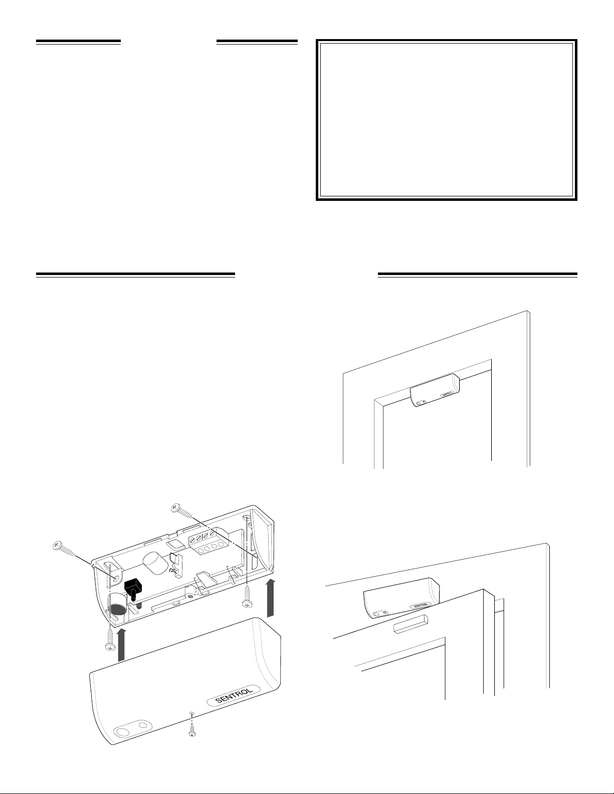
STEP 1 — MOUNTING
The 5600 sensors are designed to mount either inside the
frame (see Figure 1a) or on the facing (see Figure 1b).
Refer to Figure 2 for recommended mounting locations and
coverage range. Mounting location should provide good
mechanical coupling from glass to sensor and an
unobstructed microphone view of the glass. If structural
integrity of the frame is poor, temporarily mount sensor and
follow Step 3 for range testing. Do not exceed the tested
range of the sensor.
Figure 1a
Sentrol
ShatterPoint
Glassbreak Sensor
Installation Instructions
Models
564503 (3 Volt) 564506 (6 Volt)
™
Note: For applications with more than one framed window
or French style doors and windows, use multiple 5600s or a
ShatterPro II.
Use provided screws to securely mount the sensor to the
frame. A loosely mounted sensor will not perform correctly.
The small screw must be used to permanently attach the
cover.
Figure 1b
Page 2
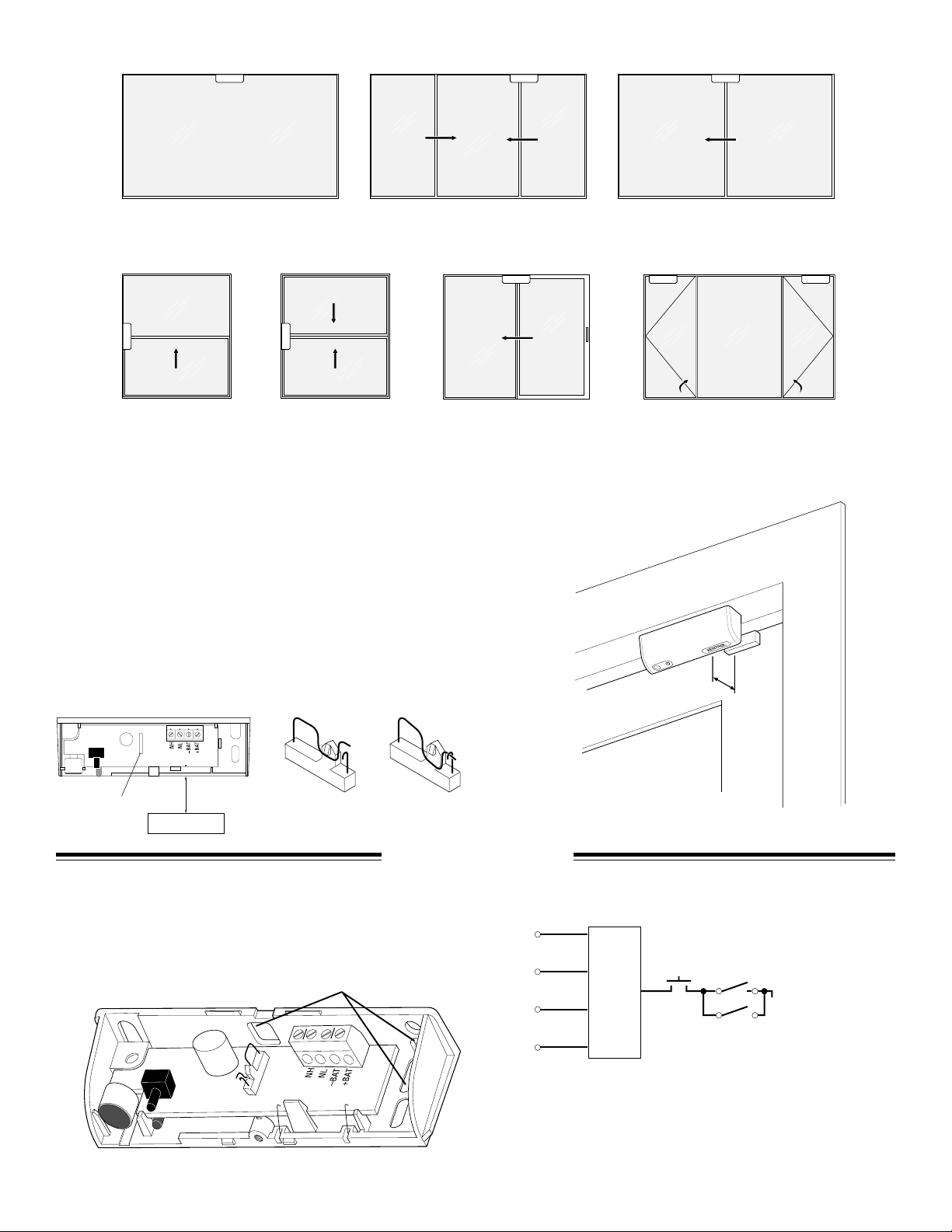
Figure 2
PICTURE WINDOW
VERTICAL SLIDE DOUBLE-HUNG HINGED CASEMENT
DOUBLE SLIDER
PATIO DOOR
Note: Not recommended for French style doors or windows, use a ShatterPro II.
Reed Switch
The magnet must be mounted on the moving portion of the
Figure 3
window or door. Magnet placement must be within 3/4"
(1.9cm) of sensor, either behind or below (see Figure 3).
Center magnet as marked on the printed circuit board.
Place magnet cover over center of mounting plate and slide
to either left or right until housing snaps in place.
Note: Mounting sensor or magnet on steel surfaces will
reduce gap.
HORIZONTAL SLIDER
The magnetic contact can be deactivated by closing wire
jumper switch.
CENTER MAGNET HERE
Jumper
Switch
3/4"
MAGNET
–Switch open –Switch closed
–Reed enabled –Reed disabled
STEP 2 — WIRING
The 5600 sensor provides multiple wiring entrances (see
Figure 4). Use rear holes or knock-out as needed. It is
recommended to tape over unused holes.
Figure 4
Wire Exits
2
3/4"
Output Circuit (shown powered)
N.H.
N.L.
Tamper Reed
Sensor
– Bat
+ Bat
Jumper Switch
Note: Sensor will remain in an alarm state as long as the
tamper or reed is open.
Page 3

TRANSMITTER WIRING DIAGRAMS — 3 VOLT
−
+
N.L.
−
3.5V
Alarm
(N.H.)
Alarm
(N.L.)
+ Battery
– Battery
SENTROL UNIVERSAL
TRANSMITTER
−
3.5V
+
+ Battery
– Battery
Alarm
Alarm
(N.L.)
(N.H.)
NAPCo GEM-Trans2
123
A
A
+
–
l
a
(
(
N
N
r
m
.
H
.
)
l
B
B
a
r
a
a
m
t
.
L
.
)
t
t
t
e
e
r
r
y
y
564503-W
Legend:
Alarm NL—White Wire
3V (+)—Red Wire
Grnd (-)—Black Wire
ITI 3.5V SYSTEM IV
−
3.5V
+
A
A
larm
larm
(N
(N
.L.)
.H
.)
– B
N.L.
+ B
attery
−
attery
ITI 3.5V Programmable
−
3.5V
N.L.
+
+
–
A
A
la
la
(N
(N
r
m
.L
.H
.)
.)
B
B
a
r
m
t
te
r
y
ITI 3.5V Learn mode
a
tte
r
y
3
Page 4

TRANSMITTER WIRING DIAGRAMS — 3 VOLT (continued)
+
−
N.L.
−
3.5V
A
la
rm
(N
.H
.)
A
la
rm
(N
.L
.)
+
B
a
tte
ry
–
B
a
tte
ry
Ademco model 5816
& 5816MN
DSC WSS-907U
A
A
+
–
B
la
(N
(N
r
m
.H
.)
*Remove top Battery and slide gold
terminal clip between + end of
bottom-right battery and circuit
board battery terminal. Rotate gold
clip out of the way and replace top
Battery.
B
la
a
r
a
m
tte
.L
tte
.)
ry
ry
Inovonics FA-210
3.0V
+ Battery
– Battery
Alarm
Alarm
(N.L.)
(N.H.)
*For Inovonics FA series
receivers the contact selection
header must be correspondingly
set to NC.
Linear DXT-31
3V
(6V)
TRANSMITTER WIRING DIAGRAMS — 6 VOLT
Linear T-90
(6V)
3V
43
21
OPEN
*564506-W
564506-W
Legend:
Alarm NL—White Wire
6V (+)—Red Wire
Grnd (-)—Black Wire
A
A
+
Alarm
(N.H.)
Alarm
(N.L.)
– Battery
+ Battery
(N
–
B
la
rm
.H
.)
B
la
(N
rm
a
a
tte
.L
tte
.)
ry
ry
4
Page 5

STEP 3 — TESTING
Installation Test
The sensor is ready to test once installed with cover on and
powered, no test mode setting is necessary. To test sensor,
perform Range testing to ensure adequate vibration
coupling to the sensor. After range is verified, perform
Alarm test.
1. Range testing – Indicates sensor is within detection range
by blinking the LED twice slowly. To test, rap the glass
lightly with the handle of a large screwdriver. Start close
to the sensor and proceed to furthest point of glass. If
LED does not blink over the entire glass, better coupling
between glass and sensor is needed. Try adding screws to
the window support into the frame near the sensor or use
longer screws to mount sensor, being careful not to
damage the window.
2. Alarm testing – Using the Sentrol 5709C hand-held
tester (set for proper glass type), hold tester close to
sensor and press test button while simultaneously
rapping lightly on the glass with the handle of a
screwdriver. Proper sequence is important to alarm
sensor. When alarmed, the outputs will change state for 4
seconds and the LED will turn on solid for 4 seconds
then turn off. This verifies that the sensor has triggered
an alarm. The panel should report an alarm condition
from the attached transmitter. The reed switch can be
tested by opening the window or door a few inches.
Caution: Hinged style door or window will significantly
reduce range. Test seismic signal thoroughly.
Sensor Self-Tests
All the 5600s perform a processor self-test at power up. If
the processor finds a faulty condition, the LED will stay lit
and the output will stay in an alarm state.
Normal operation will clear the LED and cause normal
output states.
During operation, the processor periodically tests itself for
conditions that could impede performance. If the processor
malfunctions, it will reset itself and perform a power-up
self-test. If memory fails, the LED will blink continuously at
1Hz (1/2 second on, 1/2 second off) to signal the trouble.
Promptly replace a sensor which indicates a faulty
condition.
Note: Test sensor at least annually for proper
operation.
Note: The 5645’s do not have alarm memory.
Installation Tests
Test Action LED Indication
No Flash
Range Rap Glass Out of Range Within Within
Test Range Range
Alarm Rap Glass & No Alarm No Alarm Alarm
Test Key 5709C
End-User Rap Glass Too Far From Sensor or Hardware Fault Sensor Alarm
Test Okay
2 Slow
Flashes
Sensor Self-Test
Test Condition Indication
Power-up test Normal LED Turns Off, Normal Output States
Faulty LED Solid On, Alarm Condition
Memory test Normal LED is off
Faulty LED Flashes at 1Hz (1/2 sec. on, 1/2 sec. off) continuously
Solid On
5
Page 6

SPECIFICATIONS DIMENSIONS
Electrical
Voltage (564503) .............................................................2–5V DC
Voltage (564506) .............................................................4–9V DC
Current (564503) ..................................................... <10µA typical
Current (564506) ..................................................... <20µA typical
Wire Terminals ............................................................ 22-18 AWG
Environment
Operating Temperature .................. 0° to +120°F (–18° to +50°C)
Humidity ............................................ 10% to 90% noncondensing
RF Immunity ............................................. 20 V/m, 1 to 1000 MHz
Features
Glass Types
Plate ........................................ 3/32'' (2.4 mm) to 3/8" (9 mm)
Tempered .............................. 1/8'' (3.2 mm) to 1/4" (6.4 mm)
Laminated .............................. 1/8'' (3.2 mm) to 1/4" (6.4 mm)
Wired ................................................................ 1/4" (6.4 mm)
Mounting Location ............................................................... Frame
Range of Glass Surface Covered (Radius from sensor)
Single-pane window ........................................ up to 10' (3 m)
Multi-pane window .......................................... up to 8' (2.4 m)
Sliding-glass door ........................................... up to 8' (2.4 m)
Minimum Glass Size ............................. 18" (45 cm) x 18" (45 cm)
Magnet Gap Distance ............................... 3/4" (1.9 cm) maximum
Note: Mounting sensor or magnet on steel will reduce gap.
Housing Material ......................................... Flame Retardant ABS
Color ..................................................................................... White
Sensor
Magnet
0.375''
0.953 cm
0.395''
1.00 cm
3.95''
10.0 cm
2.26''
5.74 cm
1.25''
3.18 cm
0.9''
2.3 cm
Note: This equipment has been tested and found to comply with the limits for a Class B digital device, pursuant to Part 15 of
the FCC Rules. These limits are designed to provide reasonable protection against harmful interference in a residential
installation. This equipment generates, uses and can radiate radio frequency energy and, if not installed and used in accordance with the instructions, may cause harmful interference to radio communications. However, there is no guarantee that
interference will not occur in a particular installation. If this equipment does cause harmful interference to radio or television reception, which can be determined by turning the equipment off and on, the user is encouraged to try to correct the
interference by one or more of the following measures:
• Re-orient or relocate the receiving antenna.
• Increase the separation between the equipment and receiver.
• Connect the equipment into an outlet on a circuit different from that to which the receiver is connected.
• Consult the dealer or an experienced radio/TV technician for help.
This device complies with Part 15 of the FCC Rules. Operation is subject to the following two conditions: (1) This device
may not cause harmful interference, and (2) this device must accept any interference received, including interference that
may cause undesired operation.
Protected under U.S. and foreign patents including: 3,863,250; 4,745,398; 4,837,558; 5,192,931 and other patents pending.
Ordering Information
Description Model Number Color
Wireless ShatterPoint™, 3 Volt with magnetic contact 564503-W/M white/mahogany
Wireless ShatterPoint™, 6 Volt with magnetic contact 564506-W/M white/mahogany
Hand-held Tester 5709C-W white
Replacement magnet 1838-N/M white/mahogany
SENTROL, inc
CORPORATE HEADQUARTERS
12345 SW Leveton Dr., Tualatin, OR 97062
Tel.: 503.692.4052 Fax: 503.691.7566
http://www.sentrol.com
U.S. & Canada: 800.547.2556
Technical Service: 800.648.7424
FaxBack: 1.800.483.2495
Sentrol reserves the right
to change specifications
without notice.
©1998 Sentrol, Inc.
G-3190-0198
14258 Rev. B
 Loading...