

Page 1
ShatterPoint
™
Glassbreak Sensor
Models
5600-W, 5605-W, 5620-W, 5625-W
Installation Instructions
Description
The 5600 Glassbreak Sensors are designed to detect
breaking glass caused by forced entry into a protected
window or door. The ‘Tru-Dual’ transducer design provides
excellent false-alarm immunity in noisy environments.
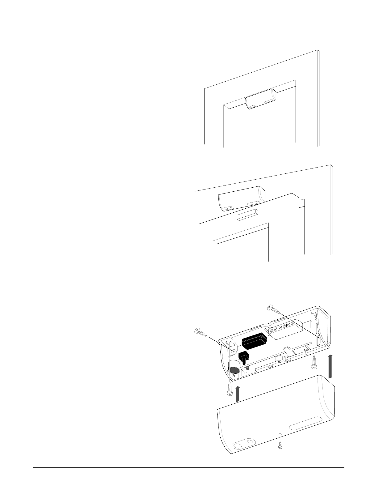
Figure 1a. Frame Mounting
The 5600 Sensors process both acoustic and vibration
information to identify breaking windows. Frame mounting
the 5600 Sensors eliminates detection concerns with drapes
and blinds. The built-in reed switch models provide
protection against forced opening of windows or doors, as
well as breaking glass.
Note These sensors may not consistently detect
cracks, bullets, or similar breaks. Glassbreak sensors
should always be backed up by interior protection such
as a motion detector.
Mounting
The 5600 sensors are designed to mount either inside the
frame (see Figure 1a) or on the facing (see Figure 1b). Refer
to Figure 3 for recommended mounting locations and
coverage range. The mounting location should provide good
mechanical coupling from glass to sensor and an
unobstructed microphone view of the glass. If structural
integrity of the frame is poor, temporarily mount the sensor
and follow the steps in Testing for range testing. Do not
exceed the tested range of the sensor.
Figure 1b. Facing Mounting
Note For applications with more than one framed
window, use multiple 5600s or a ShatterPro II.
Use the screws provided to mount the sensor securely to the
frame. A loosely mounted sensor will not perform correctly.
The small cover screw must be used to permanently attach
the cover (see Figure 2).
ShatterPoint Glassbreak Sensor
Cover Screw
Figure 2. Mounting and Cover Screws
1
Page 2
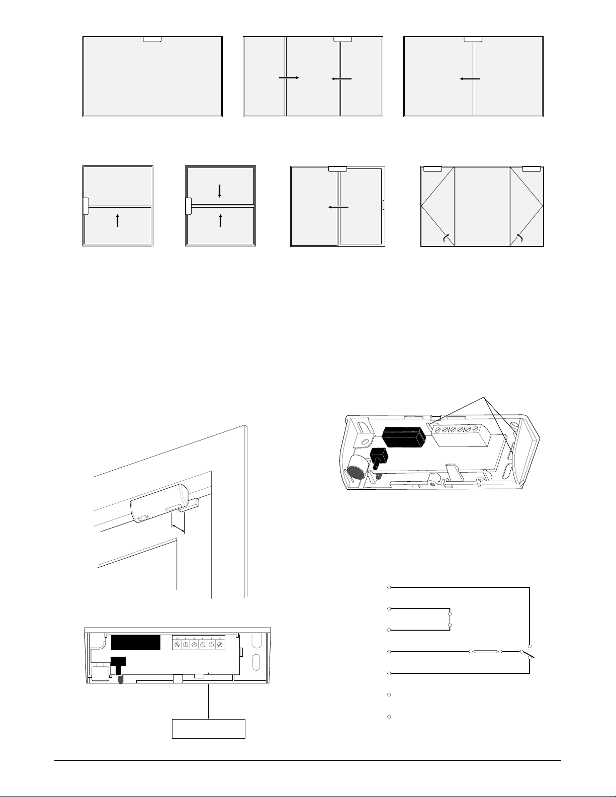
Picture Window
Double Slider
Horizontal Slider
Vertical Slide Double Hung Patio Door
Figure 3. Mounting Locations
Reed Switch Models
Models 5620 and 5625 require the magnet be mounted on
the moving portion of the window or door. Magnet
placement must be within 3/4" (19mm) of sensor, either
behind or below (see Figure 4). Center magnet as marked
on the printed circuit board (see Figure 5).
Note Mounting sensor or magnet on steel surfaces will
reduce gap.
3/4"
(19mm)
Hinged Casement
Wiring
The 5600 sensor provides multiple wiring entrances (see
Figure 6). Use rear holes or knock-out as needed. It is
recommended to tape over unused holes.
Wire Entrances
Figure 6. Wire Entrances
Figure 4. Magnet Placement
Figure 5. Centering the Magnet
2
CENTER MAGNET HERE
3/4" (19mm)
MAGNET
N.O.
TAMP
TAMP
REED (5620 Series only)
COM
N.C.
-GND
+12V
Figure 7. Output Circuit (shown powered)
ShatterPoint Glassbreak Sensor
Page 3

Testing
The 5600 features installation tests and a hand-clap
end-user test.
End-User Test
Simply clap hands within 3 feet (1m) of the sensor and the
LED will flash quickly indicating the sensor is powered and
functioning properly.
Installation Test
The sensor is ready to test once installed with cover on and
powered, no test mode is necessary. To test sensor, perform
range testing to ensure adequate vibration coupling to
sensor. After range is verified, perform alarm test.
1. Range testing – The LED blinks slowly two times to
indicate the sensor is within detection range. To test, rap
the glass lightly with the handle of a screwdriver. Start
close to the sensor and proceed to furthest point of glass.
If LED flashes quickly, better coupling between glass and
sensor may be needed.
2. Alarm testing – Using the 5709C hand-held tester (set
for proper glass type), hold tester at furthest point of
glass and press test button while simultaneously rapping
lightly on the glass with the handle of a screwdriver.
When in alarm, the relay will open for 4 seconds and the
LED will turn on solid for 1 minute then turn off. This
verifies that the sensor triggers an alarm with the control
panel. The reed switch is in series with the alarm loop
and can be tested by opening the window or door a few
inches.
Caution Hinged style doors or windows will
significantly reduce range. Test seismic signal
thoroughly.
Alarm Memory
All 5600 Sensors include the alarm memory feature. This
helps the installer find which sensor alarmed. After an
alarm, the LED will turn on solid for 1 minute then turn off.
Any subsequent hand claps or raps to the window will result
in the LED turning on solid for 15 seconds and then turning
off (relay remains closed unless sensor alarms during this
test). To reset the sensor’s alarm memory, briefly
disconnect power.
Sensor Self-Tests
All 5600 Sensors perform a processor self-test at power up.
If the processor finds a faulty condition, the LED will stay
lit and the relay will not energize.
Normal operation will clear the LED and energize the relay.
During operation, the processor periodically tests itself for
conditions that could impede performance. If the processor
malfunctions, it will reset itself and perform a power-up
self-test. If memory fails, the LED will blink continuously
at 1Hz (1/2 second on, 1/2 second off) to signal the trouble.
Promptly replace a sensor which indicates a faulty
condition.
Note Test sensors at least annually for proper
operation.
Installation Tests
Test Action
Range Rap Glass Out of Range Out of Within Within Range
Test Range Range
Alarm Rap Glass & No Alarm No Alarm No Alarm Alarm
Test Key 5709C
End-User Hand Clap Sensor Hardware Hardware Fault or Alarm
Test or Too Far From Sensor or Hardware Fault Okay Fault Memory Indicated
Key 5709C
Alarm Rap Glass, No Alarm No Alarm Sensor has Alarmed Since
Memory Hand Clap, or Too Far From Sensor in Memory in Memory Last Power-Up
LED Indication
No Flash
3 Fast
Flashes
2 Slow
Flashes
Solid On
Sensor Self-Test
Test Condition LED Indication
Power-up test Normal LED Turns Off, Relay Energizes
Faulty LED Solid On, Relay Never Energizes, Alarm Condition
Memory test Normal No Indication, Sensor Functions Normally
Faulty LED Flashes at 1Hz (1/2 sec. on, 1/2 sec. off)
ShatterPoint Glassbreak Sensor
3
Page 4

Specifications Dimensions
x
Voltage ..................................................................... 9 – 16V DC
Current.............................................. 12mA typical, 20mA max.
Relay Output: Normal.........................................<15 W (closed)
Alarm ............................................................ >1 MW (open)
Open 4 seconds upon alarm
Maximum loop rating .................................. 16V DC, 50mA
Wire Terminals ........................................................ 22-18 AWG
Operating Temperature ............... 0° to +120°F (–18° to +50°C)
Humidity ........................................ 10% to 90% noncondensing
Lightning Suppression ..................... 400 Watts for 1msec pulse
RF Immunity .........................................20 V/m, 1 to 1000 MHz
Glass Types
Plate ......................................3/32'' (2.4mm) to 3/8" (9mm)
Tempered.............................1/8'' (3.2mm) to 1/4" (6.4mm)
Laminated............................1/8'' (3.2mm) to 1/4" (6.4mm)
Wired .............................................................. 1/4" (6.4mm)
Mounting Location ............................................................ Frame
Range of glass surface covered (radius from sensor)
Single-pane window ..................................... up to 10' (3m)
Multi-pane window...................................... up to 8' (2.4m)
Sliding-glass door ........................................ up to 8' (2.4m)
Armor coated glass ...................................... up to 8' (2.4m)
Minimum Glass Size.................... 12" (305mm) x 12" (305mm)
Note: Mounting sensor or magnet on steel surface will
reduce gap.
Magnet Gap Distance.............................3/4" (19mm) maximum
Housing Material ..................................... Flame Retardant ABS
Color............................................................ White or Mahogany
Sensor
Magnet
1.5"
(38mm)
3.95"
(100mm)
(10mm)
0.38"
0.25"
(6mm)
1.25"
(32mm)
0.9"
(23mm)
FCC
This device complies with part 15 of the FCC Rules.
Operation is subject to the following two conditions: (1)
This device may not cause harmful interference, and (2)
this device must accept any interference received, including
interference that may cause undesired operation.
Ordering Information
Description Model Number Color Choices
ShatterPoint™ 5600-W White
ShatterPoint™, with Form C relay and tamper switch 5605-W White
ShatterPoint™, with magnetic contact 5620-W White
ShatterPoint™, with Form C relay, tamper switch and magnetic contact 5625-W/M White or Mahogany
Hand-held Tester 5709C-W White
Replacement magnet 1838-N/M Cloud White or Mahogany
www.GE-Interlogix.com
© 2003 GE INTERLOGIX
12345 SW Leveton Drive
Tualatin, OR 97062
Phone: 503-692-4052
USA & Canada: 800-547-2556
Technical Service: 800-648-7424
FaxBack: 800-483-2495
GE Interlogi
14329 Rev B 05/03
 Loading...