

Page 1

TDZ 2000 GL1/ExtremeZ GL1
System Reference
July 1998
DHA027210
Page 2

Copyright
1998 Intergraph Computer Systems. All rights reserved. This document contains information protected by copyright, trade secret, and
trademark law. This document may not, in whole or in part, be reproduced in any form or by any means, or be used to make any
derivative work, without written consent from Intergraph Computer Systems.
Use, duplication, or disclosure by the United States Government is subject to restrictions as set forth in subdivision (c)(1)(ii) of the rights in
technical data and computer software clause at DFARS 252.227-7013. Unpublished rights are reserved under the copyright laws of the
United States.
Intergraph Computer Systems, Huntsville AL 35894-0001
Notice
Information in this document is subject to change without notice and should not be considered a commitment by Intergraph Computer
Systems. Intergraph Computer Systems shall not be liable for technical or editorial errors in, or omissions from, this document. Intergraph
Computer Systems shall not be liable for incidental or consequential damages resulting from the furnishing or use of this document.
All warranties given by Intergraph Computer Systems about equipment or software are set forth in your purchase contract. Nothing stated
in, or implied by, this document or its contents shall be considered or deemed a modification or amendment of such warrantites.
Trademarks
Intergraph and the Intergraph logo are registered trademarks, and Ultra-Tower, TDZ, and Intense 3D are trademarks, of Intergraph
Computer Systems.
Microsoft, Windows, and MS-DOS are registered trademarks, and Windows NT is a trademark, of Microsoft Corporation.
Other brands and product names are trademarks of their respective owners.
FCC/DOC Compliance
This equipment has been tested and found to comply with the limits for a Class A digital device, pursuant to part 15 of the FCC Rules.
These limits are designed to provide reasonable protection against harmful interference when the equipment is operated in a commercial
environment. This equipment generates, uses, and can radiate radio frequency energy. If the equipment is not installed and used in
accordance with the instruction manual, it may cause harmful interference to radio communications.
Operation of this equipment in a residential area is likely to cause harmful interference in which case the user will be required to correct the
interference at his own expense.
This Class A digital apparatus meets all requirements of the Canadian Interference-Causing Equipment Regulations. Cet appareil
numérique de la classe A respecte toutes les exigencies du Règlement sur le materiél brouilleur du Canada.
Warnings
The service and upgrade instructions should be performed by qualified personnel only. Qualified personel do not have to be Intergraph
service personnel. Those who are familiar with servicing computers can follow instructions in a manual to service equipment, and do so
without harm to themselves or damage to the equipment.
Changes or modifications made to the system that are not approved by the party responsible for compliance could void the user's authority
to operate the equipment.
To reduce the risk of electrical shock, do not attempt to open the equipment unless instructed. Do not use a tool for purposes other than
instructed.
There is a danger of explosion if the battery is incorrectly replaced. Replace the battery only with the same or equivalent type as
recommended by the manufacturer. Dispose of used batteries according to the manufacturer's instructions.
There are no user serviceable parts within the power supply. In the event of failure, the power supply must be replaced by qualified service
personnel. Use Intergraph power supplies only.
Page 3

Notes
Read all safety and operating instructions before using the equipment. Keep these instructions for future reference. Follow all warnings on
the equipment or in the operating instructions.
This device is designed and manufactured to comply with approved safety standards for information processing and business equipment.
Page 4

Page 5

Contents
Introduction.................................................................................................................ix
About This Document.................................................................................................. ix
Document Conventions................................................................................................ ix
Customer Support..........................................................................................................x
Hardware and Software Support Services.........................................................x
World Wide Web.............................................................................................x
Intergraph Bulletin Board Service ....................................................................x
FAXLink........................................................................................................ xi
Telephone ...................................................................................................... xi
More Support Options.................................................................................... xi
1 Accessing the System................................................................................................1
Tools .............................................................................................................................2
Protecting Against Electrostatic Discharge.....................................................................2
Opening and Closing the Case .......................................................................................2
System Illustrations........................................................................................................4
2 Servicing the System................................................................................................7
Case Components ..........................................................................................................8
Peripheral Drives.........................................................................................................11
Floppy Disk Drive.......................................................................................... 11
CD-ROM Drive..............................................................................................12
External Bay Disk Drives............................................................................... 13
Internal Bay Disk Drives................................................................................15
Power Supply...............................................................................................................17
Processor Modules.......................................................................................................18
Heat-Sink Mounting Brackets......................................................................................20
Retension Modules.......................................................................................................20
SIMMs ........................................................................................................................21
System Board...............................................................................................................22
Expansion Cards.......................................................................................................... 24
Fans.............................................................................................................................24
Lithium (CMOS/Clock) Battery...................................................................................25
LEDs, Light Pipe, and Power Switch ...........................................................................26
v
3 Upgrading the System............................................................................................29
Adding Memory...........................................................................................................30
Precautions.....................................................................................................30
64 MB Memory Modules................................................................................30
Memory Configurations .................................................................................31
Adding a Processor......................................................................................................32
Single-to-Dual Upgrade..................................................................................32
Page 6

vi
Adding Expansion Cards .............................................................................................33
Slot Locations................................................................................................34
Installing Expansion Cards ............................................................................34
Assigning System Resources.......................................................................... 35
Adding Drives and Devices..........................................................................................35
Device Locations............................................................................................36
Adding External SCSI Drives ......................................................................................37
SCSI Cable Length Guidelines.......................................................................37
SCSI Cable Quality Guidelines.......................................................................38
SCSI ID Guidelines........................................................................................38
SCSI Termination Guidelines for External Devices ........................................38
Connecting the Device ...................................................................................39
Changing SCSI Adapter or Device Settings....................................................39
4 System Hardware Overview and Specifications....................................................41
Hardware Overview.....................................................................................................42
Functional Diagram .....................................................................................................43
System Board...............................................................................................................44
System Configuration Summary...................................................................................44
System Model Number.................................................................................................45
Specifications...............................................................................................................47
Hardware Monitoring ..................................................................................................47
Optional Hardware.......................................................................................................48
5 System Board ..........................................................................................................49
Major Features.............................................................................................................50
Connectors, Slots, and Sockets.....................................................................................51
Connectors...................................................................................................................52
Jumper Functions......................................................................................................... 54
Jumper Settings ...........................................................................................................54
Processor and Bus Speed................................................................................54
DRAM Voltage Select....................................................................................54
I/O Select.......................................................................................................55
LM78 IRQ Select...........................................................................................55
CMOS and Password Reset............................................................................ 55
External Ports and Pinouts ...........................................................................................56
PCI to ISA Bus Interrupt Mapping...............................................................................61
6 Peripherals..............................................................................................................63
Peripheral Cables.........................................................................................................64
EIDE Cable Connection Locations.................................................................64
Floppy Cable Connection Locations...............................................................64
Peripheral Configuration..............................................................................................65
EIDE CD-ROM Drive....................................................................................65
SCSI CD-Recorder.........................................................................................66
Iomega Jaz 1 GB Internal SCSI Drive ............................................................67
Page 7

Floppy Disk Drive.......................................................................................... 68
4.0 GB and 9.0 GB Disk Drives .....................................................................68
7 Power Supply and Cooling Fans............................................................................. 71
Power Supply...............................................................................................................72
Power Supply Cable Routing.......................................................................... 73
P1 Pinout .......................................................................................................73
P2 - P5 Pinouts...............................................................................................73
P6 Pinout .......................................................................................................73
Cooling Fans ...............................................................................................................74
Index...........................................................................................................................75
vii
Page 8

viii
Page 9

Introduction
This System Reference provides information necessary to service and upgrade a TDZ 2000
GL1 or ExtremeZ GL1 system. For information on how to set up the system for use, refer to
the TDZ 2000 GL1/ExtremeZ GL1 System Setup guide.
About This Document
This document is organized as follows:
u
Chapter 1, “Accessing the System,” provides information you need to gain access to the
system.
u
Chapter 2, “Servicing the System,” describes how to replace standard parts in the
system.
u
Chapter 3, “Upgrading the System,” describes how to upgrade system components.
u
Chapter 4, “System Hardware Overview and Specifications,” provides general technical
information about the system hardware.
ix
u
Chapter 5, “System Board,” provides information on the system board, its components,
and its connections.
u
Chapter 6, “Peripherals,” provides information on cabling and configuration of common
system peripherals.
u
Chapter 7, “Power Supply and Cooling Fans,” provides information on the system’s
power supply and cooling fans.
Document Conventions
Bold
Italic Variable values that you supply, or cross-references.
Monospace
SMALL CAPS Key names on the keyboard, such as D, ALT or F3. Names of files and
CTRL+D Press a key while simultaneously pressing another key; for example, press
Commands, words, or characters that you key in literally.
Output displayed on the screen.
directories. You can type filenames and directory names in the dialog boxes
or the command line in lowercase unless directed otherwise.
CTRL and D simultaneously.
Page 10

x
Customer Support
Intergraph Computer Systems offers an assortment of customer support options.
Hardware and Software Support Services
Intergraph Computer Systems provides a variety of hardware services for Intergraph and
third-party equipment. Services include warranty upgrades, repair depot service, on-site
hardware maintenance, system administration, and network consulting. Hardware
purchased from Intergraph Computer Systems includes a factory warranty ranging from 30
days to three years. A detailed warranty description is available on the World Wide Web;
see the Support pages at http://www.intergraph.com/ics.
Intergraph Computer Systems provides complimentary software support for 30 or 90 days
following shipment of a hardware or software product. This includes World Wide Web
access, Intergraph Bulletin Board Service access, FAXLink service, and telephone (Help
Desk) support. At the end of the complimentary support period, you can purchase other
levels of software support.
World Wide Web
You can visit Intergraph Computer Systems on the World Wide Web at
http://www.intergraph.com/ics. On these pages, you can get news and product
information, technical support information, software updates and fixes, and more.
Intergraph Bulletin Board Service
On the Intergraph Bulletin Board Service (IBBS), you can get technical support information,
software updates and fixes, and more.
To connect to the IBBS:
1. Set your system’s communications protocol for eight (8) data bits, no parity, one (1) stop
bit, and any baud rate up to 14,400.
2. Using a modem, call 1-256-730-8786. Outside the United States, call one of the mirror
sites listed on World Wide Web; see the Software Support pages at
http://www.intergraph.com.
3. At the login prompt, key in your user ID. If you have not connected before, key in new
to create a user ID.
4. Follow the menus to find what you need. The IBBS provides clear choices and online
help.
Page 11

If you have trouble connecting to or using the IBBS, call the Customer Response Center at 1800-633-7248 (product entry IBBS) or leave a message for the IBBS System Operator at 1256-730-1413.
FAXLink
To use the FAXLink:
u
u
Telephone
To get customer support by telephone:
u
u
xi
Call 1-800-240-4300 for information on how to get technical support information using
the FAXLink.
Call 1-256-730-9000 to get documents (up to five per call).
In the United States, call 1-800-633-7248 between the hours of 7:00 a.m. and 7:00
p.m. Central Time, Monday through Friday (except holidays).
Outside the United States, contact your local Intergraph Computer Systems subsidiary or
distributor.
Have the following information available when you call:
u
Your service number, which identifies your site to Intergraph Computer Systems. You
use your service number for warranty or maintenance calls.
u
Your Customer Personal Identification Number (CPIN). You get a CPIN the first time
you call the Customer Response Center; it is associated with your service number for
future call logging.
u
The product’s name or model number.
u
The product’s serial number. Software product serial numbers are included in the
product packaging. Hardware product serial numbers are on a sticker affixed to the
hardware product.
u
Your name and telephone number.
u
A brief description of the question or problem.
More Support Options
To get information on more customer support options:
u
Visit the Support pages on the World Wide Web at http://www.intergraph.com/ics.
u
For hardware support questions in the United States, call 1-800-763-0242.
Page 12

xii
u
For software support questions in the United States, call 1-800-345-4856.
u
Outside the United States, contact your local Intergraph Computer Systems subsidiary or
distributor.
Page 13

1 A ccessing the System
This chapter lists hand tools and describes servicing restrictions, methods for avoiding
electrostatic discharge, and how to remove and attach cover panels from a TDZ 2000 GL1 or
ExtremeZ GL1 workstation.
This system features a chassis architecture designed to make upgrades and expansion simple.
The design provides easy access to PCI and ISA card slots, memory, processors, and power
supply.
NOTE “Right side” and “left side” are as seen from the front of the unit.
CAUTION Follow all warnings and cautions in the servicing instructions. If you fail to follow
documented, approved procedures, personal injury and damage to equipment can result.
CAUTION Use an antistatic wrist strap for all servicing procedures to avoid the possibility o f
electrostatic discharge.
Tools .............................................................................................................................2
Protecting Against Electrostatic Discharge.....................................................................2
Opening and Closing the Case .......................................................................................2
System Illustrations........................................................................................................4
1
Page 14

2
Tools
You will need the following tools to service the system:
u
Antistatic wrist strap
u
Antistatic mat connected to an earth ground
u
Quarter-inch nutdriver
u
No. 1 and No. 2 Phillips screwdrivers
u
Small or medium flat-blade standard screwdriver
You do not need any tools to open the TDZ 2000 GL1/ExtremeZ GL1 case.
Protecting Against Electrostatic Discharge
Electrostatic discharge (ESD) can damage sensitive components inside the unit. Take the
following precautions when working with internal components:
u
Touch the bare metal of the chassis to ensure the chassis and your body are at the same
electric potential.
u
Attach the antistatic wrist strap to its connector on the antistatic mat. Ensure that the
metal conductor bead in the elastic sleeve of the antistatic strap contacts bare skin.
u
Handle all printed circuit boards as little as possible and by the edges only.
u
Leave new parts in their protective packaging until you install them.
Opening and Closing the Case
Opening the system for service or upgrades consists of two simple steps. Remove the top
cover first, then remove the left side panel. No tools are needed. You need only remove the
top cover and left side panel for most routine service procedures. See Chapter 2, “Servicing
the System,” for additional details on removing and replacing case components.
CAUTION Do not use the bottom portion of the face panel or the lip at the top, rear of the unit as a hand
hold when moving the system. Equipment damage and personal injury can result.
The left side panel has a tab that closes an interlock switch inside the power supply.
CAUTION Before you open the case, shut down the system and turn off power to the system and
external devices (including peripheral drives and display). Use caution to avoid injury when
lifting the computer or removing covers and other hardware.
Page 15
NOTE Removing the right side panel is necessary only for servicing internal bay disk drives, the
plastic cowling on the right panel, or the face panel.
To open the case:
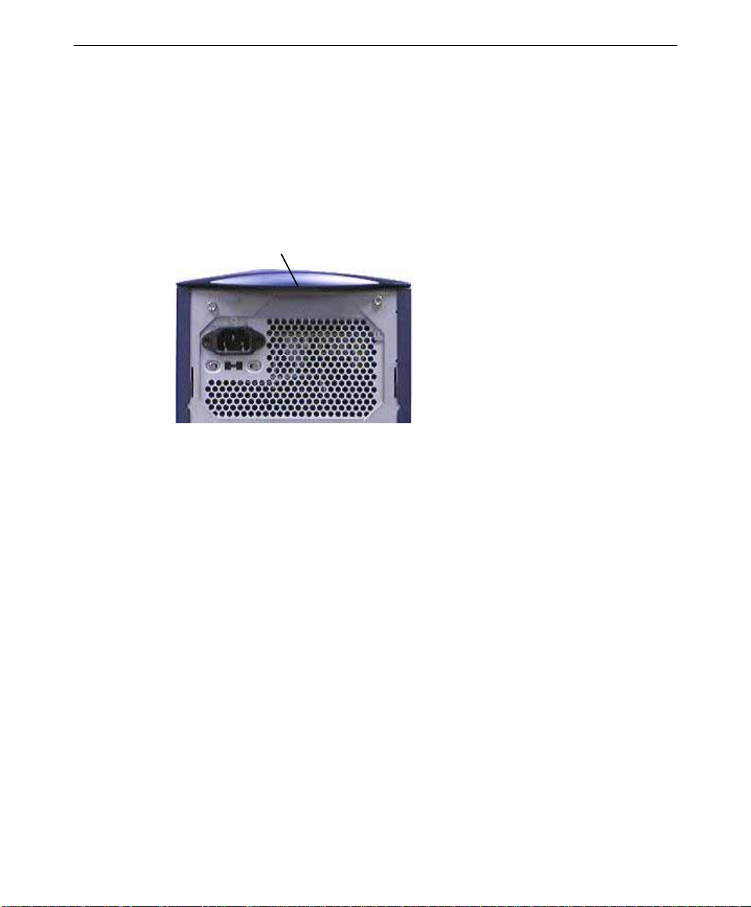
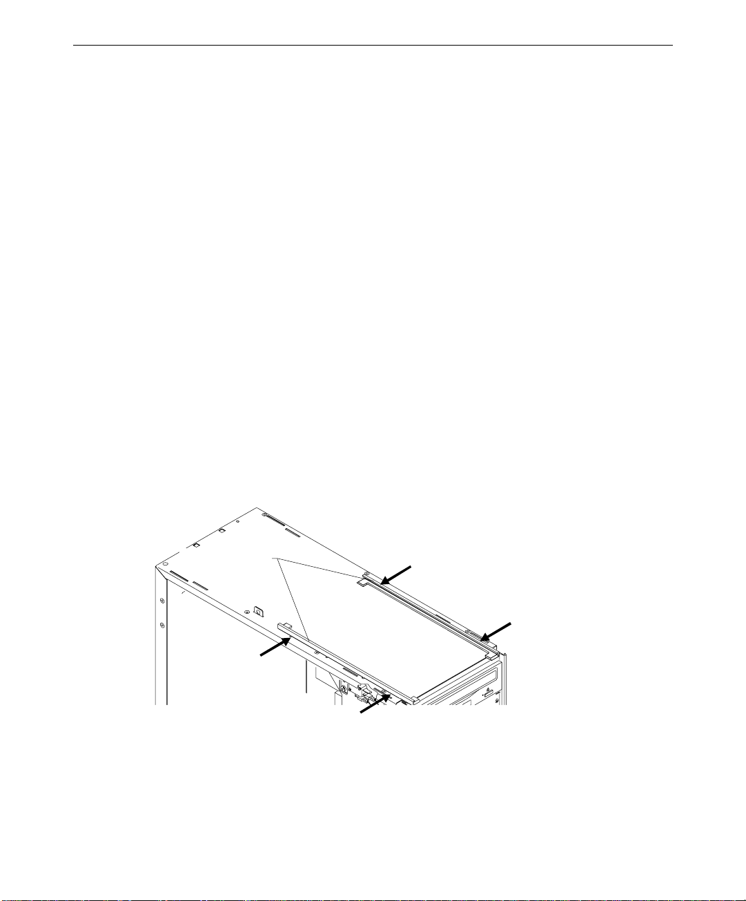
1. Grasp the lip on the top cover at the rear of the system and press up on the release. See
the following figure.
2. Keep pressing the release, slide the top cover back until it stops, remove it from the
chassis, and set it aside.
Press up on release,
located under lip
3
3. Grasp the cowling at the bottom of the left side panel and lift.
4. Slide the left side panel back until it stops, remove it from the chassis, and set it aside.
5. Repeat steps 4 and 5 to remove the right side panel, if necessary.
To close the case:
1. Place the side panel on the chassis so that all tabs on the rear of the chassis insert into
their slots.
2. Push the side panel toward the front of the chassis, then push down to seat the panel.
3. Repeat steps 1 and 2 to install the remaining side panel, if necessary.
4. Place the top cover on the chassis so that all tabs are inserted into their slots.
5. Slide the top cover forward until it locks into place.
CAUTION After servicing or upgrading the system, always replace the covers that were removed. The
covers ensure the system maintains proper air flow, so internal components do not overheat
and fail. The covers also ensure that electromagnetic interference (EMI) emissions remain
below the standard requirements.
Page 16
4
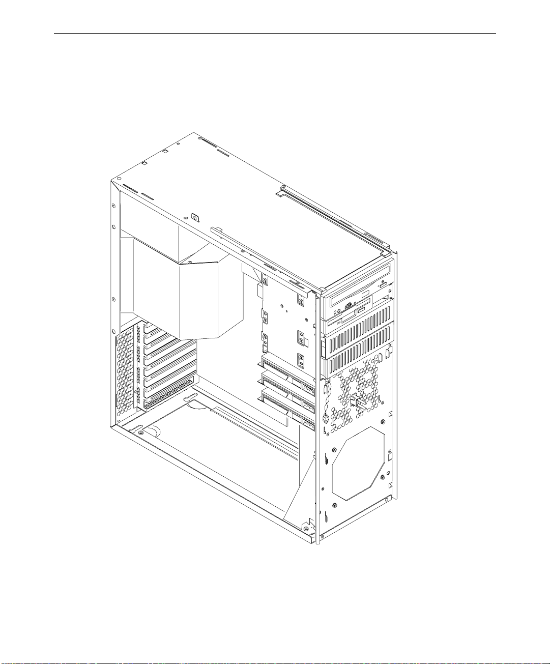
System Illustrations
The front, left view below shows major parts of the system without covers, cables, system
board and option cards.
Page 17
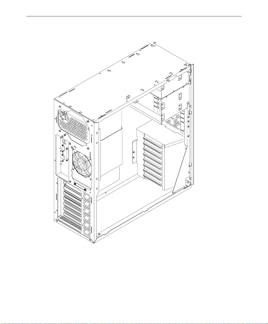
The back, left view below shows the chassis with all major components removed.
5
Page 18

6
Page 19

2 Servicing the System
This chapter describes how to replace the standard parts within a TDZ 2000 GL1 or
ExtremeZ GL1 system. Obey all warning and caution labels while replacing parts.
Note that internal parts servicing procedures assume you have removed the left side panel
from the system. After you have finished servicing the system, replace panels as described in
Chapter 1, “Accessing the System.”
WARNING Disconnect the system from AC power before servicing internal components! Failure
to remove AC power may result in equipment damage or personal injury.
NOTE See Chapter 1, “Accessing the System,” for instructions on opening the system and
protecting against electrostatic discharge.
CAUTION Follow all warnings and cautions in servicing instructions. If you fail to follow documented,
approved procedures, personal injury or damage to equipment can result.
CAUTION Use an antistatic wrist strap for all servicing procedures to avoid the possibility of
electrostatic discharge.
7
CAUTION Do not overtighten screws and other fasteners to avoid damaging threads.
Case Components ..........................................................................................................8
Peripheral Drives.........................................................................................................11
Floppy Disk Drive.......................................................................................... 11
CD-ROM Drive..............................................................................................12
External Bay Disk Drives............................................................................... 13
Internal Bay Disk Drives................................................................................15
Power Supply...............................................................................................................17
Processor Modules.......................................................................................................18
Heat-Sink Mounting Brackets......................................................................................20
Retension Modules.......................................................................................................20
SIMMs ........................................................................................................................21
System Board...............................................................................................................22
Expansion Cards.......................................................................................................... 24
Fans.............................................................................................................................24
Lithium (CMOS/Clock) Battery...................................................................................25
LEDs, Light Pipe, and Power Switch ...........................................................................26
Page 20
8
Case Components
Ordinarily you will not need to replace any of the external case components unless they are
broken or cosmetically damaged. All case components are designed for durability, but the
item that may require replacement first is the door and hinge assembly.
To replace the hinge or door, you must first remove the top cover. To replace the face panel,
you must remove the top cover and the door.
To replace the top cover:
1. Remove the top cover. See Chapter 1, “Accessing the System,” for details.
2. Install the new cover.
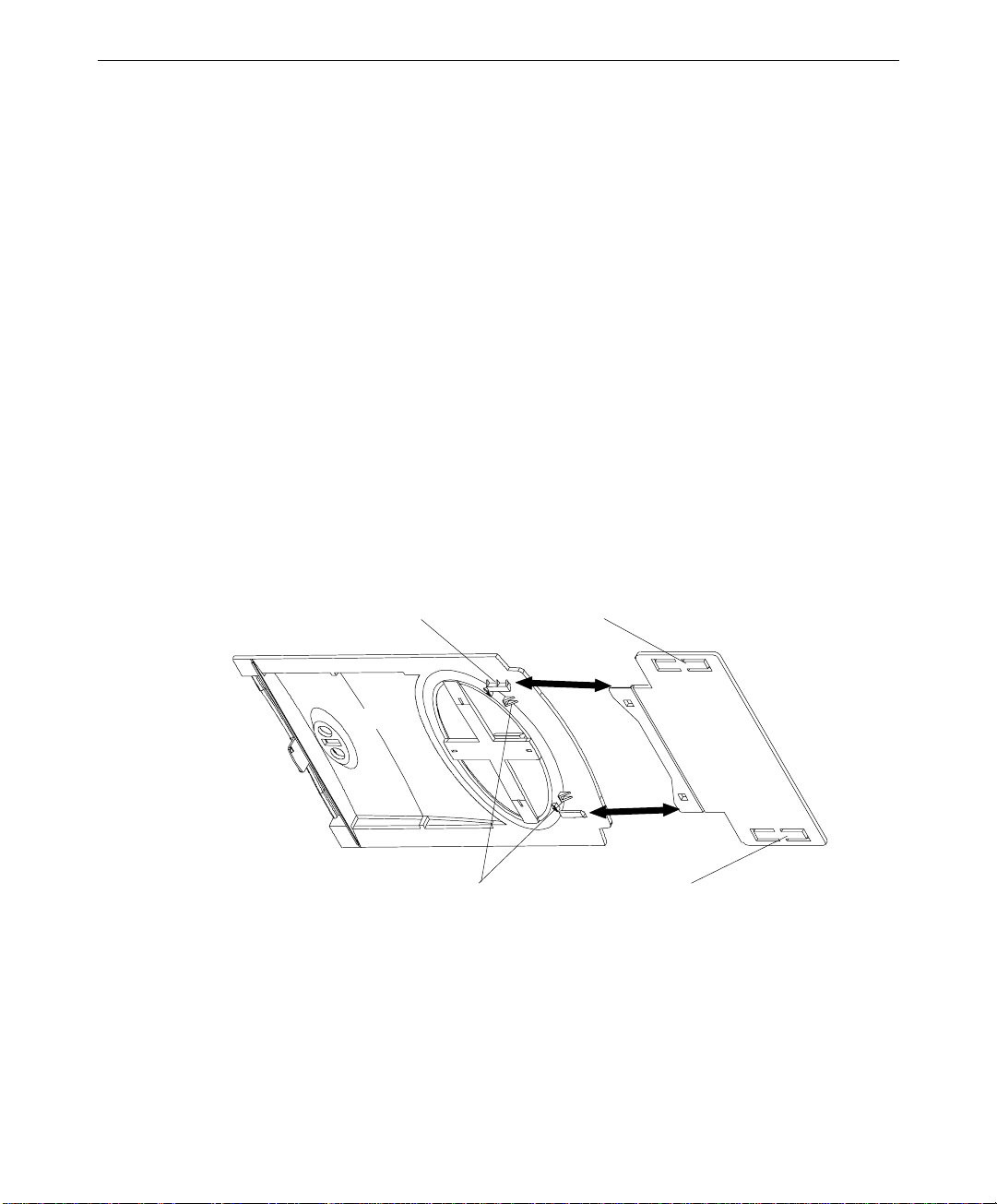
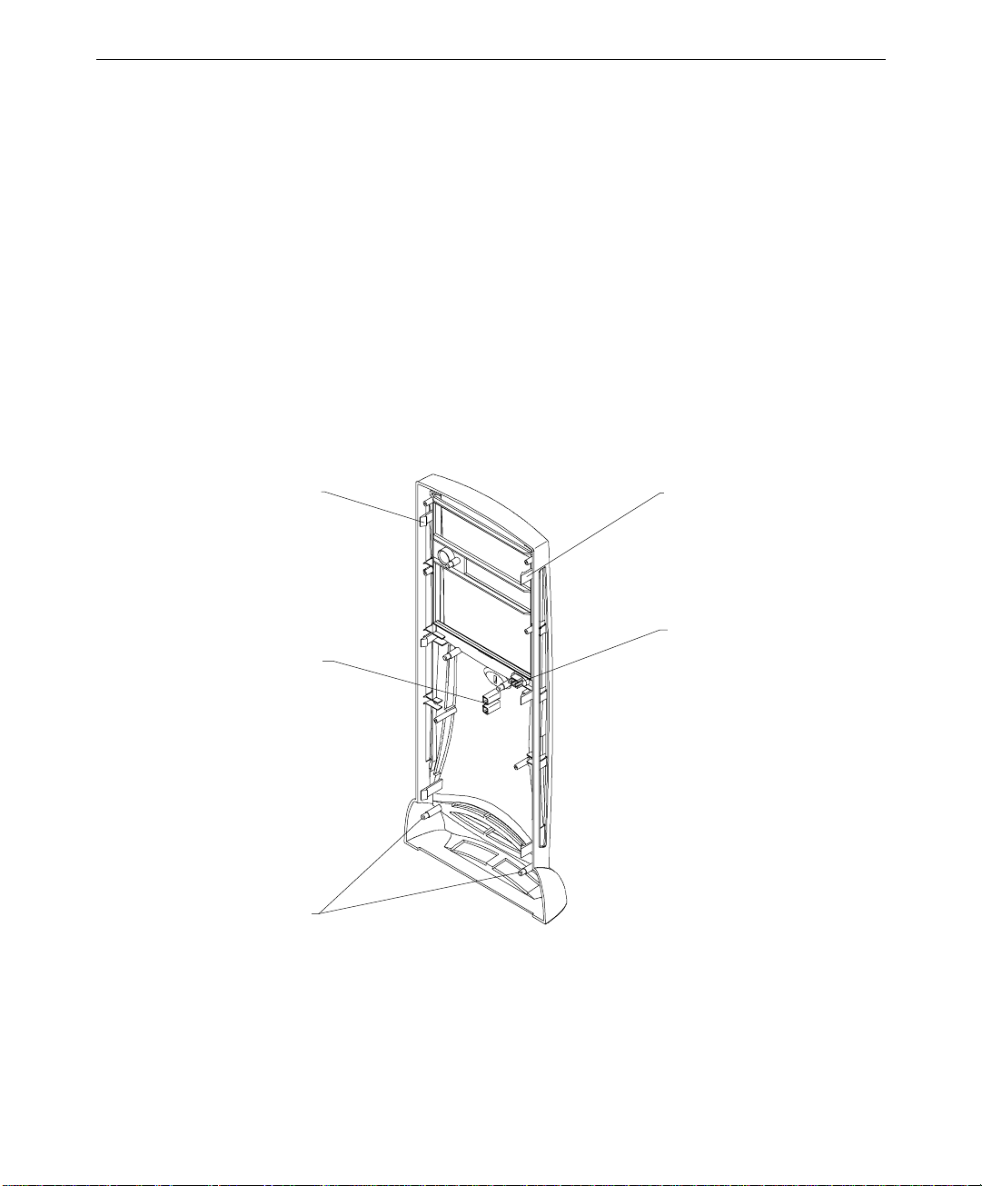
To replace the door assembly:
1. Remove the top cover. See Chapter 1, “Accessing the System,” for details.
2. Lift the door and hold it at a 90-degree angle from the face panel.
3. Insert a small flat-blade screwdriver between the door and hinge, near one of the square
holes on the underside of the door.
Guide slot (1 per side)
Door
Locking tabs
Stop tabs
Hinge
Stop tabs
4. Pull the door toward you and pry the hinge and door apart until one side of the door
releases from its locking tab.
5. Repeat steps 3 and 4 for the other side of the door hinge.
6. Remove the door.
Page 21
7. Do both of the following on the underside of the door:
−
Spread the release tabs on the large emblem and remove it
−
Squeeze the release tabs on the small emblem and remove it
8. Slide the hinge toward the front of the chassis until it stops.
9. Use a flat-blade screwdriver and pry each of the stop tabs on the hinge until the hinge
releases from the rails.
10. Orient the new hinge so that the locking tabs face down and insert the new hinge into
the track and push it forward until it stops.
11. Hold the hinge, align the beveled edges of the hinge with the guide slots on the door,
and push the door firmly onto the hinge until it snaps into place.
12. Press the two emblems onto the door until they snap into place.
13. Operate the door to test its movement.
14. Install the top cover. See Chapter 1, “Accessing the System,” for details.
To replace the hinge rails:
1. Remove the door. See the procedure above for details.
9
2. Slide the hinge toward the front of the chassis until it stops.
3. Use a flat-blade screwdriver and pry each of the stop tabs on the hinge until the hinge
releases from the rails.
Hinge rails
4. Remove the hinge from the rail.
5. Press a hinge rail toward the middle of the chassis until all four tabs release.
6. Lift the hinge rail off the chassis.
Page 22
10
7. Orient the new hinge rail the same way as the one you removed, place the tabs in the
slots, and press outward until the rail snaps into place.
8. From the front of the chassis, slide the hinge into the rails.
To replace the face panel:
1. Remove the top cover and both side panels. See Chapter 1, “Accessing the System,” for
details.
2. Remove the door. See the “To replace the door assembly” procedure above for details.
3. Push the hinge back, away from the front of the chassis.
4. Use a flat-blade screwdriver to gently pry and release each of the plastic tabs on both
sides of the chassis. The tabs on the right side of the chassis are recessed. First release
the bottom tabs, release the middle tabs, and then release the top tabs.
CAUTION Release the tabs with care. Do not apply more pressure than necessary.
Tab
(3 per side)
Light pipe gui des
Standoff posts
(4 per si d e)
Tab
(3 per side)
Power switch
Standb y sw i tch
5. Pull the face panel away from the chassis slightly to ensure all tabs are released.
6. Grasp the left side of the face panel and pivot it left to expose the power switch and
cable.
7. Spread the switch mount locking tabs, grasp the switch, and pull the switch out of its
mount.
Page 23

8. Turn the face panel downward until the power switch button drops out.
9. Place the left side of the new face panel near the left, front of the chassis and orient the
switch so that the black and green wires are at the bottom.
10. Push the power switch into the mount until it snaps into place.
11. Place the power switch button into its hole and push firmly until it seats.
12. Align the new face panel with the tab notches and light pipe guides, and carefully push
the panel onto the chassis until all tabs engage.
13. Install the door, left and right side panels, and top cover.
To replace the left or right side plastic cowling:
1. Remove the top cover, then remove the side panel that has the plastic you want to
replace. See Chapter 1, “Accessing the System,” for details.
2. Place the side panel, with the cowling side down, on a flat, padded surface.
3. Remove the screw that secures the plastic to the side panel.
4. Grasp one side of the panel, press the release tabs, and lift the panel off the plastic.
5. Turn the side panel over and press the new plastic onto the panel until the release tabs
engage.
11
6. Turn the side panel over and install the screw.
7. Install the side panel onto the chassis.
8. Install the top cover. See Chapter 1, “Accessing the System,” for details.
Peripheral Drives
This section explains how to replace the floppy, CD-ROM, and internal and external bay
disk drives. See Chapter 6, “Peripherals,” for details on drive configuration and cables.
Floppy Disk Drive
To replace the floppy disk drive:
1. Disconnect the power cable and data cable from the drive. Note the position of the red
stripe on the data cable.
2. Remove the two screws that secure the floppy drive to the chassis. See the following
figure.
Page 24
12
CD-ROM mounting
screws
Floppy drive mounting
screws
3. From inside the chassis, push the back of the floppy drive until the bezel clears the
chassis, and slide the device out.
4. Slide the new floppy drive into the chassis and align the mounting holes.
5. Install the two mounting screws.
6. Connect the data cable and the power cable.
CD-ROM Drive
To replace the CD-ROM drive:
1. Disconnect the power cable, data cable, and audio cable from the CD-ROM drive.
2. Remove the screws that secure the CD-ROM drive to the chassis. See the previous
figure.
3. From inside the chassis, push the back of the CD-ROM until the bezel clears the chassis,
then slide the device out.
4. Remove the mounting guide from the right side of the CD-ROM. See the following
figure.
Page 25
Mounting guide
5. Note the jumper settings on the rear of the CD-ROM.
6. Set the master/slave jumper to the same position as the old drive.
7. Install the mounting guide on the right side of the new CD-ROM.
8. Slide the new CD-ROM drive into the chassis and align the mounting holes.
13
9. Install the screws that secure the CD-ROM to the chassis.
10. Connect the audio cable, data cable, and power cable.
External Bay Disk Drives
If a Kingston or other brand of removable disk module is installed in the external bay, see
the vendor documentation for disk drive and module replacement instructions.
To replace an external bay disk drive:
1. Disconnect the SCSI cable and power cable from the disk drive.
2. Remove the two screws that secure the external bay disk drive tray to the chassis. See
the following figure.
Page 26
14
External bay
mounting screws
3. From inside the chassis, push the tray out of the external bay, grasp the front of the tray,
and then slide it out of the bay.
4. Remove the screws that secure the disk drive to the tray and remove the drive.
5. Do one of the following:
−
If installing an EIDE drive, set the master/slave jumper setting on the new drive to
match that of the old drive
−
If installing a SCSI drive, set the SCSI ID on the new drive to match that of the old
drive.
See Chapter 6, “Peripherals,” for details on these tasks.
6. Place the disk drive in the tray, align the mounting holes, and install the mounting
screws that secure the disk drive to the tray. See the following figure.
Page 27
Mount ing guide
Drive tray
15
7. Slide the tray assembly into the chassis and align the mounting holes.
8. Install the screws that secure the tray to the chassis.
9. Connect the SCSI cable and the power cable to the disk drive.
Internal Bay Disk Drives
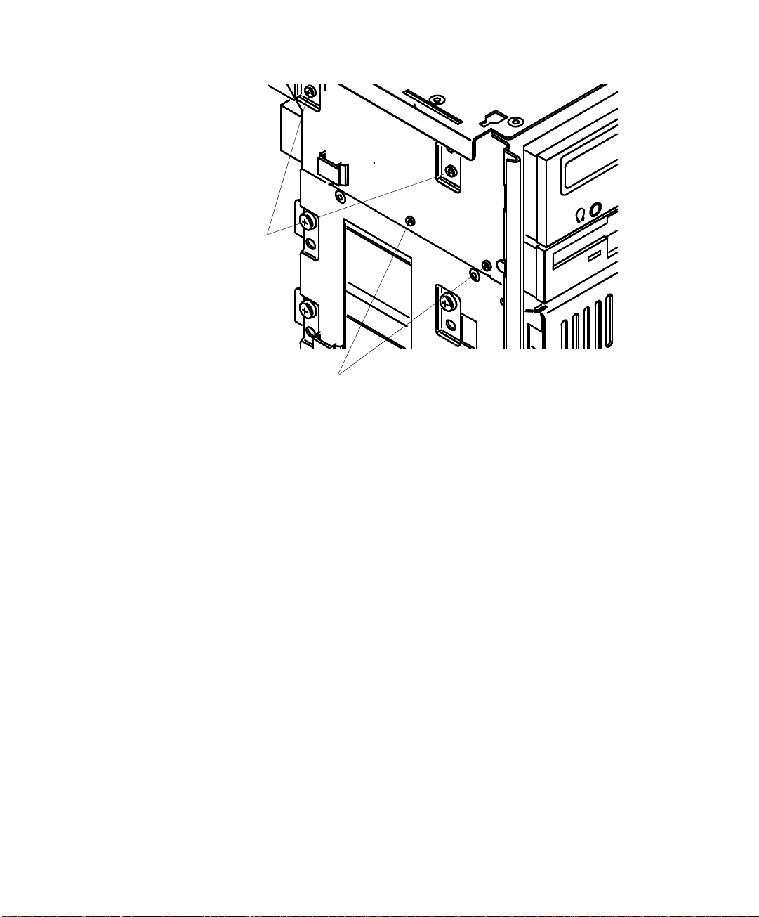
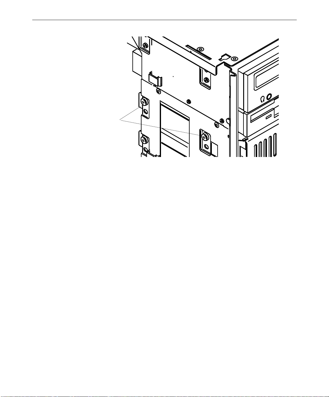
To replace an internal bay disk drive:
1. Disconnect the data cable and power cable from the disk drive.
2. Remove the two screws that secure the drive bracket assembly to the left side of the
chassis.
3. Grasp the drive bracket assembly and remove the screw that secures the bracket to the
right side of the chassis.
4. Pull the drive bracket assembly out of the chassis.
5. Remove the four screws that secure the old drive to the bracket.
Access hole (2)
Page 28

16
6. Do one of the following:
−
If installing an EIDE drive, set the master/slave jumper setting on the new drive to
match that of the old drive
−
If installing a SCSI drive, set the SCSI ID on the new drive to match that of the old
drive.
See Chapter 6, “Peripherals,” for details on these tasks.
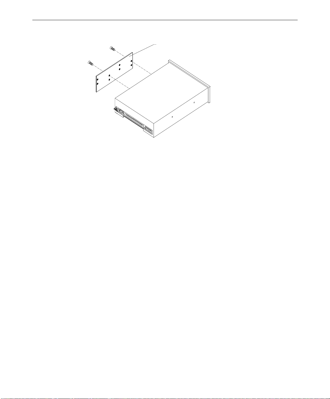
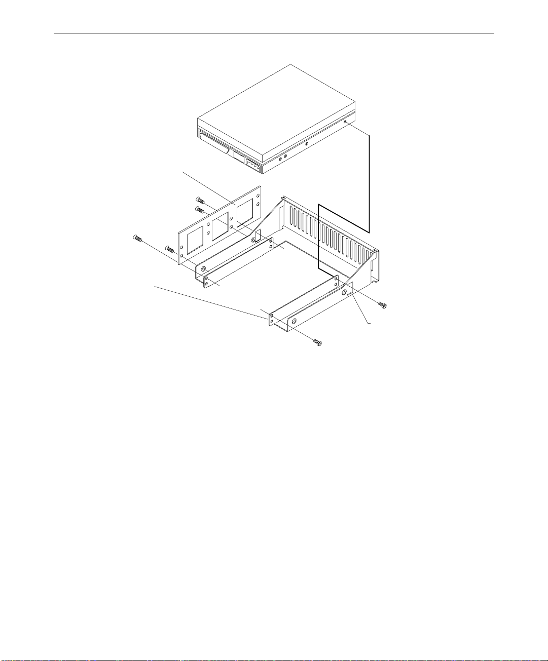
7. Install the new drive on the bracket.
Alignment tabs
Rear mounting tab
Front mounting tabs
Page 29

8. Insert the alignment tabs into the appropriate slots in the chassis.
Screw hol e s for front mounti ng tabs
9. Install the two screws that secure the drive bracket assembly front mounting tabs to the
chassis.
17
10. Install the screw that secures the drive bracket assembly to the right side of the chassis.
11. Install the right side panel.
12. Connect the data cable and the power cable to the new drive.
Power Supply
See Chapter 7, “Power Supply, Fans, and Hardware Monitoring Devices,” for details on the
power supply.
To replace the power supply:
1. Unplug the AC power cord from the rear of the unit.
2. Note the location of all power cable connectors on the system board and peripheral
devices.
3. Disconnect all power cables from all internal devices and the system board.
4. Remove the four outer screws from the rear of the power supply, as shown in the
following figure.
NOTE Support the power supply as you remove the screws. Do not to let the power supply fall as
you remove the fourth screw.
Page 30

18
Inner screws
Outer screws
5. Remove the old power supply.
6. Remove the inner screws securing the rear plate to the power supply, as shown in the
previous figure.
7. Attach the rear plate to the new power supply using the inner screws, and then install
the new power supply using the outer screws.
8. Connect the power cables to the system board and internal devices. See Chapter 7,
“Power Supply, Fans, and Hardware Monitoring Devices,” for connection details.
9. Plug the AC power cord into its connector on the back of the chassis.
Processor Modules
The TDZ 2000 GL1 and ExtremeZ GL1 systems are designed to support 266, 300, and 333
MHz Pentium II processors. See the system board diagram in Chapter 5, “System Board,”
for connector and socket locations.
Outer screws
To replace a passive processor module:
1. Remove the heat-sink lock from within the heat-sink fins, if necessary, by pressing the
ends of the lock inward and pulling outward.
Page 31

Heat-sink lock
2. Press the locking tabs on the top corners of the processor module inward, towards each
other, until they click into the release position.
3. Slide the processor module out of the retension module.
4. Remove the new processor from its antistatic package, and align the processor module
over the retension module. The processor module is keyed and fits only one way.
5. Press the processor module down until it seats.
6. Press the processor module locking tabs outward until they click into the locked
position.
19
7. Install the heat-sink lock between the heat-sink fins, if necessary, by sliding the lock
between the fins and pressing it onto the heat-sink lock mounting posts.
To replace an active processor module:
1. Disconnect the processor’s cooling fan power cable from the processor fan power
connector on the system board.
2. Press the locking tabs on the top corners of the processor module inward, towards each
other, until they click into the release position.
3. Slide the processor module out of the retension module.
4. Remove the new processor from its antistatic package, and align the processor module
over the retension module. The processor module is keyed and fits only one way.
5. Press the processor module down until it seats.
6. Press the processor module locking tabs outward until they click into the locked
position.
7. Connect the processor’s cooling fan power cable to the processor fan power connector on
the system board.
Page 32

20
Heat-Sink Mounting Brackets
Pentium II processors equipped with heat-sink fins use heat-sink locks fastened to mounting
brackets to secure them to the system board, providing additional stability to the processor
module. See the system board diagram in Chapter 5, “System Board,” for connector and
socket locations.
To replace a heat-sink mounting bracket:
1. Remove the processor module. See the “Processor Modules” section above for details.
2. Two mounting locks on the rear side of the system board secure the mounting bracket.
Remove these locks, and then remove the mounting bracket from the system board.
3. The heat-sink mounting bracket has two pins on the bottom and four pins on the top.
The bottom two pins are of different sizes. The size of the pins and the holes in the
system board determine the correct orientation.
Insert the new heat-sink mounting bracket into the appropriate holes on the system
board. The bracket will click when it is correctly inserted. Ensure the four top pins are
closest to the processor slot.
4. Lock the heat-sink mounting bracket to the system board by inserting the two mounting
locks into the pins of the heat-sink mounting bracket, which are below the system board.
The locks will click when they are securely fastened.
Retension Modules
Pentium II processors are secured to the system board using retension modules. See the
system board diagram in Chapter 5, “System Board,” for connector and socket locations.
NOTE You do not need to replace a retension module to replace a processor module.
Ret ensi on module
Page 33

To replace a retension module:
1. Remove the processor module. See the “Processor Modules” section above for details.
2. Remove the heat-sink locks, if necessary. See the “Heat-Sink Mounting Brackets”
section above for details.
3. Remove the screws securing the retension module to the system board, and remove the
retension module.
4. Locate the key pin on one end of the processor slot on the board. Carefully line up the
key notch on the new retention module with the key pin on the processor slot. The key
pin on the processor slot indicates the correct orientation of the CPU.
5. Lower the retention module down over the processor slot so that the retention module
seats flatly against the system board. Tighten the screws in a clockwise manner to
secure the module to the board.
WARNING Do not overtighten the screws as you may damage the module and/or the system
board.
6. Replace the heat-sink locks, if necessary. See the “Heat-Sink Mounting Brackets”
section above for details.
7. Replace the processor module. See the “Processor Modules” section above for details.
21
SIMMs
See the section, “Adding Memory,” in Chapter 3, “Upgrading the System,” for important
details on handling SIMMs. The SIMM sockets are located to the right of the processors on
the system board. See the system board diagram in Chapter 5, “System Board,” for socket
locations.
To replace a SIMM:
1. Press the release tabs outward, away from each other.
2. Grasp the top edge of the SIMM and pull it out of the socket.
3. Remove the new SIMM from the antistatic package.
4. Orient the SIMM so that the notches match the keys in the socket.
5. Insert the SIMM at a 45-degree angle into the socket.
6. Push gently straight down until the release tabs snap into place, as shown in the
following figure.
Page 34

22
Locked module
Push in this direction to
lock into place
Empty socket
7. When you restart the computer, the BIOS detects the new memory automatically.
System Board
You must swap the SIMMs and processor module(s) from the old system board to the new
one if you replace the system board. See the system board diagram in Chapter 5, “System
Board,” for connector and socket locations.
Note that a number of Fastex fasteners are mounted in the right side of the chassis to secure
the system board and supports for the processor retention modules. Do not overtighten the
screws to these fasteners. If overtightened, the fasteners may distort.
Page 35

Hole in right side of chassis
Fastex fastener
To remove the system board:
1. Lay the chassis down on its right side.
2. Note the locations where all cables are connected to the system board.
3. Disconnect all cables from the system board.
4. Note the locations of the expansion cards, remove them, and place the cards on an
antistatic surface.
5. Remove SIMMs and processor module(s) and place them on an antistatic surface. See
the respective procedures above for details on removing these components.
6. Remove the jackscrews on all external port connectors.
WARNING Use care when removing or installing the screws to avoid damaging components on
the system board.
23
7. Remove the screws and the plastic rivets on the processor retention module(s), and
remove the retension module(s) from the chassis.
8. Remove the screws from the system board.
9. Lift the system board out of the chassis and place it on an antistatic surface.
To install a new system board:
1. Place the new system board into the chassis, align all mounting holes, and install the
jackscrews on the external port connectors.
2. Loosely install the remaining screws on the system board, except those for the processor
retension module(s). Do not tighten the screws yet.
3. Mount the retension module(s) to the system board with the plastic rivets. The retension
module(s) is keyed to the processor slots to ensure correct orientation.
4. Tighten all fasteners that secure the system board and retension module(s) to the chassis.
You may need to adjust the Fastex fasteners slightly on the right side of the chassis.
5. Install the SIMMs and processor(s) to the system board.
6. Install the expansion cards back into their original slots.
Page 36

24
7. Connect the internal cables to the system board. If you need help identifying cable
connections, see Chapter 5, “System Board.”
Expansion Cards
See the system board diagram in Chapter 5, “System Board,” for connector and socket
locations.
To replace an expansion card:
1. Disconnect the external device attached to the expansion card connector on the rear of
the system.
2. Disconnect any internal cable that connects the card to another device (if installed).
3. Remove the screw that secures the card to the left card guide.
4. Pull the expansion card straight out, and place it on an antistatic surface.
5. Slide the new card into the same slot from which you removed the old card.
6. Install the screw that secures the card to the left card guide.
7. Connect any cables from other internal devices, if installed.
8. Connect the external device to the expansion card connector on the rear of the system.
Fans
See Chapter 7, “Power Supply, Fans, and Hardware Monitoring Devices,” for details on fans.
NOTE Arrows on the fan indicate airflow direction and rotation. Ensure system fans are installed
with the airflow direction arrow pointing in the correct direction.
NOTE The entire power supply must be replaced to replace the power supply fan.
To replace the rear system fan:
1. Disconnect the fan power cable from the power supply cable.
2. Remove the four screws securing the grille and fan to the chassis.
3. Gently pull the fan inward and downward until the fan housing clears the chassis, and
then remove the fan.
4. Note the airflow direction of the fan and the position of the fan cable.
5. Ensure the airflow direction arrow on the new fan is pointing in the correct direction,
then place the new fan at an angle inside the chassis.
Page 37

6. Insert the new fan into place in the chassis.
7. Place the grille on the outside, align the mounting holes, and install the four screws. Do
not overtighten.
8. Connect the fan power cable to the power supply cable.
To replace the front system fan:
1. Remove the face panel. See the “Case Components” section above for details.
2. Remove the two screws that secure the expansion card guide to the chassis.
3. Lift the card guide up to disengage the mounting tabs, and remove it from the chassis.
4. Disconnect the fan power cable from the power supply cable.
5. Note the airflow direction of the fan.
6. Remove the four screws securing the fan to the front of the chassis and remove the fan.
7. Ensure that the airflow direction arrow on the new fan is pointing in the correct
direction and place the fan inside the chassis.
8. Align the mounting holes, and install the four screws. Do not overtighten.
9. Connect the fan power cable to the power supply cable.
25
10. Insert the card guide tabs into the slots and push the card guide down until the tabs
engage.
11. Install the two screws that secure the card guide to the chassis.
12. Install the expansion cards.
13. Install the face panel.
Lithium (CMOS/Clock) Battery
The battery is located near the bottom front of the system board. See the system board
diagram in Chapter 5, “System Board,” for details.
After you remove the battery, the system will lose its operating parameters stored in CMOS.
As a result, the system BIOS parameters are lost. Parameters include date, time, hardware
configuration, and other data.
After you install the new battery, you must reset the date and time and reconfigure the BIOS.
See the TDZ 2000 GL1/ExtremeZ GL1 System Setup for details on updating and configuring
the BIOS.
WARNING There is a danger of explosion if the battery is incorrectly replaced.
Page 38

26
WARNING Replace the battery with the same or equivalent type only, as recommended by the
battery manufacturer. Dispose of used batteries according to the battery
manufacturer’s instructions.
To replace the battery:
1. Remove any expansion cards that restrict access to the battery. See the “Expansion
Cards” above for details.
2. Note the positive orientation of the battery. Carefully remove the discharged battery by
grasping it firmly and pulling it out of the socket.
3. Install the new battery in the same orientation as the old battery.
4. Dispose of the battery according to the manufacturer’s instructions.
5. Install the expansion cards that you removed.
LEDs, Light Pipe, and Power Switch
See the system board diagram in Chapter 5, “System Board,” for connector and socket
locations. See also the “Cable Routing and Pinouts” section in Chapter 5, “System Board,”
for LED and power switch cable and connector details.
To replace an LED:
1. Remove the internal bay disk drives. See the “Internal Bay Disk Drives” section for
details.
2. Note the locations of each of the LEDs on the light pipe.
3. Remove the LED from its mount on the light pipe, then disconnect the LED cable from
its connector on the system board.
4. Remove the LED cable from the chassis.
5. Route the new LED cable through the chassis and connect it to the appropriate
connector on the system board.
6. Press the LED into its mount on the light pipe.
To replace the light pipe:
1. Remove the face panel. See the “Case Components” section above for details.
2. Remove the internal bay disk drives. See the “Internal Bay Disk Drives” section above
for details.
Page 39

3. Disconnect the LEDs from the light pipe.
(
)
Power LED
black/white wires
Top of chassis
Disk activity LED
(black/orange wires)
4. Squeeze the mounting tabs on the light pipe inward and push the light pipe through its
mounting hole.
5. From inside the chassis, remove the light pipe.
6. Orient the new light pipe so that the Power LED mounts face up, and press the light
pipe through its mounting hole until it snaps into place.
27
7. Push each of the LEDs into its respective mount on the new light pipe.
8. Install the internal bay disk drives.
9. Install the face panel.
To replace the power switch:
1. Remove the face panel. See the “Case Components” section above for details.
2. Disconnect the power switch cable connector from the system board.
3. Remove the switch cable from the chassis.
4. Insert the connector end of the switch cable through the cable access hole on the front of
the chassis and route the new switch cable through the chassis.
5. Connect the switch cable to the connector on the system board.
6. Press the switch into its mount on the face panel.
7. Install the face panel and the switch button.
Page 40

28
Page 41

3 Upgrading the System
This chapter describes upgrading memory and processors, as well as installing expansion
cards, internal SCSI drives, and external SCSI drives in your TDZ 2000 GL1 or ExtremeZ
GL1 system.
NOTE See Chapter 1, “Accessing the System,” for instructions on opening the system and
protecting against electrostatic discharge.
CAUTION Follow all warnings and cautions in servicing instructions. If you fail to follow documented,
approved procedures, personal injury and damage to equipment can result.
CAUTION Use an antistatic wrist strap for all servicing procedures to avoid the possibility of
electrostatic discharge.
CAUTION System memory modules from Intergraph Computer Systems are certified for use with
Intergraph computers at extremes of temperature and system load to ensure reliable
performance. System memory modules available from other vendors may not function
properly or reliably in your Intergraph computer.
CAUTION Do not overtighten screws and other fasteners to avoid damaging threads.
29
Adding Memory...........................................................................................................30
Precautions.....................................................................................................30
64 MB Memory Modules................................................................................30
Memory Configurations .................................................................................31
Adding a Processor......................................................................................................32
Single-to-Dual Upgrade..................................................................................32
Adding Expansion Cards .............................................................................................33
Slot Locations................................................................................................34
Installing Expansion Cards ............................................................................34
Assigning System Resources.......................................................................... 35
Adding Drives and Devices..........................................................................................35
Device Locations............................................................................................36
Adding External SCSI Drives ......................................................................................37
SCSI Cable Length Guidelines.......................................................................37
SCSI Cable Quality Guidelines.......................................................................38
SCSI ID Guidelines........................................................................................38
SCSI Termination Guidelines for External Devices ........................................38
Connecting the Device ...................................................................................39
Changing SCSI Adapter or Device Settings....................................................39
Page 42

30
Adding Memory
You can add system memory to the computer by adding or replacing Single Inline Memory
Modules (SIMMs) Memory upgrade kits from Intergraph Computer Systems contain two
SIMMs and a disposable antistatic wrist strap.
Precautions
To avoid damaging SIMMs and voiding the warranty, take the following precautions:
u
Do not touch the tin-plated finger contacts.
u
Do not bend, twist, drop, or otherwise handle SIMMs carelessly.
u
Do not expose SIMMs to moisture or extreme temperatures.
u
Do not remove SIMMs from the antistatic bag until installation.
Before you install memory, do the following:
u
Inspect SIMM keying. The finger contacts on the SIMM must match the socket
configuration. This ensures that you have the correct voltage and type of SIMM.
u
Inspect SIMM contacts. The SIMM must have tin-plated fingers that match the tinplated socket contacts.
Follow these population rules to correctly install the SIMMs:
u
Remember that you must install SIMMs two at a time.
u
Install SIMMs one bank at a time; begin with bank 0 or the first open bank; end with
bank 3.
u
Press the SIMM into the socket at a 45 degree angle. Do not rock the SIMM; apply
even pressure along the top edge of the SIMM.
64 MB Memory Modules
On a TDZ 2000 GL1 or ExtremeZ GL1, 64 MB SIMMs built with 16-Mbit DRAM memory
do not work reliably. A system that uses these SIMMs can fail to boot or to operate properly.
As a result, these SIMMs were not qualified by ICS for use in these systems. 64 MB SIMMs
built with 64-Mbit DRAM memory were found to work reliably, and were qualified for use,
in these systems.
NOTE A 64 MB SIMM built with 16 Mbit DRAM memory has either 32 (non-parity) or 36 (parity)
devices. A 64 MB SIMM built with 64 Mbit DRAM memory has either 8 (non-parity) or 12
(parity) devices.
Page 43

Memory Configurations
The following tables shows possible memory configurations. Each bank contains one socket.
31
Memory size
16 MB 4 x 32
32 MB 8 x 32
64 MB 16 x 32
Bank 0
Memory
32 MB Two 16 MB
64 MB Two 16 MB Two 16 MB
96 MB Two 16 MB Two 32 MB
128 MB Two 16 MB Two 16 MB Two 16 MB Two 16 MB
192 MB Two 32 MB Two 64 MB
256 MB Two 64 MB Two 64 MB
384 MB Two 64 MB Two 64 MB Two 32 MB Two 32 MB
512 MB Two 64 MB Two 64 MB Two 64 MB Two 64 MB
SIMMs
Two 32 MB
Two 16 MB Two 16 MB Two 16 MB
Two 32 MB Two 32 MB
Two 64 MB
Two 32 MB Two 32 MB Two 32 MB
Two 32 MB Two 32 MB Two 32 MB Two 32 MB
Two 32 MB Two 32 MB Two 64 MB
SIMM Configuration (non-ECC)
Bank 1
SIMMs
Bank 2
SIMMs
Bank 3
SIMMs
The system board features eight SIMM sockets, which combined can hold up to 512 MB of
Extended Data Out (EDO) random-access memory (RAM). See the system board diagram in
Chapter 5, “System Board,” for socket locations.
See Chapter 2, “Servicing the System,” to install a memory upgrade.
Page 44

32
Adding a Processor
You can upgrade a single processor system to a dual processor system, or you can upgrade to
a faster processor. You can install a processor module with heat sinks or a boxed (active)
processor module with integral fan.
Processors are mounted in a processor retention module which surrounds the processor slots.
See the system board diagram in Chapter 5, “System Board,” for the location of processor
slots and related connectors.
Single-to-Dual Upgrade
You can upgrade to dual processors in the following ways:
u
You can purchase a single-to-dual processor upgrade kit from Intergraph Computer
Systems. The kit contains all the hardware, software, and documentation required to
perform the upgrade.
u
You can purchase a second processor from another vendor.
After completing the hardware upgrade, you must also upgrade to a multi-processor version
of Windows NT. You can upgrade the operating system in the following ways:
u
You can purchase the Intergraph upgrade kit mentioned previously. The kit contains all
the hardware, software, and documentation required to perform the upgrade.
u
If you have or purchase a Windows NT 4.0 Workstation Resource Kit (ISBN 1-57231343-9), you can use software on the kit’s CD-ROM to upgrade Windows NT 4.0. The
files required for the upgrade are
u
While not recommended by Intergraph Computer Systems, you can back up all critical
UPTOMP.EXE , UPTOMP.INF, and UPTOMP.TXT.
system data, install the second processor, and reinstall Windows NT 4.0 to load the
required multi-processor Hardware Abstraction Layer (HAL).
To install a single-to-dual processor upgrade:
1. Install a retension module, if necessary, onto the open processor slot. See Chapter 2,
“Servicing the System,” for details.
2. Install a heat-sink mounting bracket, if necessary, into place over the open processor
slot. See Chapter 2, “Servicing the System,” for details.
3. Orient the processor module so that the heat sink fins or cooling fan points toward the
SIMM sockets, and then insert the module into the open socket of the retension module.
4. Press straight down and apply even pressure at both ends of the CPU module until it
seats. The retension module is keyed to ensure proper insertion.
Page 45

5. Press the processor module locking tabs outward until they click into the locked
position.
6. If you installed a boxed processor with integral fan into the secondary processor slot,
connect the fan power cable to the processor fan power connector on the system board.
If you installed a processor with a heat-sink, secure the heat-sink fins using a heat-sink
lock. See Chapter 2, “Servicing the System,” for details.
Adding Expansion Cards
You can install Peripheral Component Interconnect (PCI), non-compliant PCI, Industry
Standard Architecture (ISA), and Plug-n-Play (PnP) expansion cards in the system. See
below for a general description of the types of cards.
u
PCI cards contain configuration registers that define resource information to the system
during startup. PCI cards do not require manual system configuration when installing
the card. The system BIOS detects the board’s presence during startup and reads
information from the board’s configuration registers to assign the necessary system
resources.
33
NOTE All PCI expansion cards sold by Intergraph fully comply with the
Interconnect Specification, 2.1.
u
Non-compliant PCI cards mechanically comply with the Peripheral Component
Peripheral Component
Interconnect Specification 2.1, but do not contain configuration registers that allow the
system to automatically assign the necessary resources. These cards install in PCI slots,
but you must configure the BIOS to assign system resources before installing the card.
In this regard, they are like ISA cards, as described below.
u
ISA cards do not contain registers that define the resource information to the system
during startup. Therefore, you must configure the BIOS to define the card to the system
before installing the ISA card. This reserves system resources for the card.
u
PnP cards are ISA cards that contain configuration registers like PCI cards. During
startup, the system BIOS automatically detects the installed card and assigns the
necessary system resources. Since a PnP card is ISA-based, you install it in the ISA slot.
NOTE Assign system resources for an ISA card and any non-compliant PCI cards before
installation. See the “Assigning System Resources” section below.
Each installed PCI card must draw less than 25 watts of power. The total allowable
maximum wattage for PCI cards is 175 watts. The PCI slots are limited to 25 watts power
dissipation per the Peripheral Component Interconnect Specification 2.1.
Page 46

34
Slot Locations
The expansion slots are located at the bottom, left section of the system board, as shown in
the following figure. Slot 5 is a shared PCI/ISA slot. You can install a card in the number 5
PCI slot or the number 1 ISA slot, but not in both.
PCI Slo t 1
PCI Slo t 2
PCI Slo t 3
PCI Slo t 4
PCI Slot 5 (shared)
ISA Slot 1 (shared)
ISA Slot 2
ISA Slot 3
Installing Expansion Cards
If you are installing double card sets, such as a graphics card and a geometry accelerator,
repeat the following procedure for the second card. See the documentation that came with
the card for details on connecting the two cards.
For other cards, such as internal modems or SCSI adapters, see the documentation that came
with the card for details on installation, configuration, cable connections, and operation.
To install an expansion card:
1. Locate an open slot and remove the blanking plate for the slot. Keep the retaining
screw.
NOTE If you have no open slots and/or want to replace an existing expansion card, see the
instructions in Chapter 2, “Servicing the System.”
2. Remove the expansion card from its antistatic packaging.
Page 47

3. Slide the expansion card carefully into the card guides. Ensure that the connectors on
the board’s edge are aligned properly with the slot connector.
4. Push the card into the slot firmly and evenly until it is fully seated in the slot connector.
5. Inspect the connection. If it does not appear to be correct, remove and reinstall the card.
6. Install the retaining screw.
7. Attach any required cables to the internal or external connectors.
Assigning System Resources
Some expansion cards include a configuration diskette that you can use to reserve the system
resources required for the card. Other expansion cards do not include a diskette, but require
that you manually program the BIOS with the configuration information.
See Chapter 4, “Configuring the BIOS,” in the TDZ 2000 GL1/ExtremeZ GL1 System Setup
for details on assigning system resources and configuring the BIOS for expansion cards.
See Chapter 8, “Using System Resources,” in the TDZ 2000 GL1/ExtremeZ GL1 System
Setup, for a list of available system address resources (DMA, I/O, memory) and related
details.
35
NOTE Treat non-compliant PCI cards and PCMCIA cards as ISA cards for assigning system
resources.
Adding Drives and Devices
The TDZ 2000 GL1/ExtremeZ GL1 features the following peripheral bays:
u
One 3.5-inch x 1-inch external bay for floppy disk drive.
u
One 5.25-inch x 1.6-inch external bay for CD-ROM.
u
Two 5.25-inch x 1.6-inch external bays for hard disk drives or other devices.
u
Three 3.5-inch x 1.6-inch internal bays for system or optional disks.
Note the following restrictions on adding peripheral devices:
u
The bottom 5.25-inch bay (Location 4) is not designed for CD or DVD drives, or
Kingston removable disk drive modules.
u
Other than the CD-ROM drive, only one front-accessible EIDE device can be added.
This device must be installed in the bottom 5.25-inch bay (Location 4).
u
Up to two EIDE or three SCSI hard disk drives are supported internally.
Page 48

36
u
When installing 5.25-inch peripheral devices, use the screws provided in the package
found in the Accessory Box.
See the following chapters for related information and important details:
u
Chapter 5, “System Board,” for details on SCSI connector locations and pinouts.
u
Chapter 6, “Peripherals,” for details on drive locations, jumpers, and cables.
u
Chapter 7, “Power Supply, Fans, and Hardware Monitoring Devices,” for details on
power supply cable connectors and pinouts.
Remember the following when installing devices in the system’s drive bays:
u
If you are installing a SCSI drive, have the vendor’s documentation available to follow
instructions for setting the SCSI ID, enabling or disabling termination, installing device
drivers when required, and configuring other drive attributes.
u
If you are installing a drive that connects to an adapter card (such as an EIDE drive), see
the vendor’s documentation for installing the adapter card and required cables. See the
“Adding Expansion Cards” section above for details.
u
If you are installing a Kingston or other brand of removable disk drive module, see the
vendor’s documentation for installing the module, removing terminators, and setting the
SCSI ID.
Device Locations
You can add optional mass storage devices to the internal and external drive bays. The
following table provides the drive locations and related information. See the figure below.
Location
1 System disk drive Internal 3.5-inch x 1.6-inch
2 Add-on disk drive Internal 3.5-inch x 1.6-inch
3 Add-on disk drive Internal 3.5-inch x 1.6-inch
4 Add-on device External 5.25-inch x 1.6-inch
5 Add-on device External 5.25-inch x 1.6-inch
6 Floppy disk drive External 3.5-inch x 1.0-inch
7 EIDE CD-ROM External 5.25-inch x 1.6-inch
The following figure shows drive locations. Devices are installed in all locations for figure.
The EIDE CD-ROM, floppy drive, and system drive are standard. Other devices are
available as options.
NOTE If you are installing an additional EIDE device, you must mount the device in Location 4.
Drive Peripheral Bay Max Bay Capacity
Page 49

CD-ROM drive—Location 7
Floppy disk drive—Location 6
Add-on drive—Location 5
Add-on drive—Location 4
Add-on drive—Location 3
Add-on drive—Location 2
System drive—Location 1
37
See Chapter 2, “Servicing the System,” to install a memory upgrade.
Adding External SCSI Drives
You can add single-ended external SCSI drives to the system by connecting them to an
optional SCSI adapter. See the section, “Adding Expansion Cards,” above for details.
SCSI Cable Length Guidelines
The number of drives and length of the cables used to connect the drives is a factor when
using SCSI-1, Fast SCSI (SCSI-2), Ultra SCSI, and Wide Ultra SCSI drives. Fast SCSI,
Ultra SCSI, and Wide Ultra SCSI impose shorter cable restrictions than SCSI-1. The total
length of the SCSI cabling must not exceed the following:
Drives
1 to 4 19.8 ft
5 to 7 9.9 ft
NOTE The SCSI adapter counts as one device.
SCSI-1 Fast SCSI-2 Ultra SCSI Wide Ultra SCSI
(6 meters)
(3 meters)
9.9 ft
(3 meters)
9.9 ft
(3 meters)
9.9 ft
(3 meters)
4.5 ft
(1.5 meters)
9.9 ft
(3 meters)
4.5 ft
(1.5 meters)
Page 50

38
The total length of the SCSI cabling is the sum of the following:
u
SCSI cable inside each device—average 8 inches (20 cm)
u
SCSI cable between the system and the first device
u
SCSI cable between each device
SCSI Cable Quality Guidelines
To ensure data integrity and optimum performance, do the following:
u
Use only Intergraph SCSI cables. Cables from other vendors may not provide adequate
shielding.
u
Use the shortest cables possible to connect SCSI devices to the system and to each other.
NOTE Make sure the last device on a chain of external SCSI devices has an active SCSI terminator
connected to the open SCSI port. All other external SCSI devices must have SCSI
termination disabled or removed.
SCSI ID Guidelines
By default, specific devices use the following SCSI IDs:
u
SCSI adapter (optional) uses ID 7
u
Read/write CD-ROM (optional) drive uses ID 4
u
Iomega Jaz drive (optional) uses ID 6
NOTE To easily determine the ID of each SCSI device on the system, restart the system. When the
BIOS screen displays, look for the list of SCSI devices and write down the ID for each device.
Some SCSI devices have push switches to set the ID, while others have DIP switches or
jumpers. See the vendor documentation for details on setting the ID.
SCSI Termination Guidelines for External Devices
Follow the guidelines below for terminating SCSI devices:
u
Enable termination on the last external drive on the SCSI cable chain.
u
Disable termination on all other external drives on the SCSI cable chain.
u
Use only an active terminator on externally-terminated devices.
Page 51

Connecting the Device
If your system has an optional SCSI adapter card installed, you can connect external SCSI
devices to the adapter’s external SCSI port.
To add an external SCSI device:
1. Connect one end of the external SCSI cable to the external port of the SCSI adapter:
2. Connect the other end of the cable to the SCSI device.
3. Set the SCSI ID of the device to an unused number.
4. If the SCSI device is:
−
the last or only device on the SCSI chain, enable SCSI termination
−
NOT the last or only device on the SCSI chain, disable SCSI termination
5. Ensure that the power switch on the device is in the off position, and then connect the
power cord to the device and then to an AC receptacle.
6. Turn on the power to the device and any other devices on the SCSI chain.
7. Start the system. If necessary, install the software drivers and configure the drive
according to the vendor’s instructions.
39
Changing SCSI Adapter or Device Settings
Depending on your system configuration or the capabilities of SCSI devices connected to
your system, you may need to change adapter or device settings. See the SCSI adapter
documentation delivered with the system for more information.
Page 52

40
Page 53

4 System Hardware Overview and
Specifications
This chapter contains general, technical information about the hardware in a TDZ 2000 GL1
or ExtremeZ GL1 system.
Hardware Overview.....................................................................................................42
Functional Diagram .....................................................................................................43
System Board...............................................................................................................44
System Configuration Summary...................................................................................44
System Model Number.................................................................................................45
Specifications...............................................................................................................47
Hardware Monitoring ..................................................................................................47
Optional Hardware.......................................................................................................48
41
Page 54

42
(
)
Hardware Overview
The following figure shows the major parts and assemblies inside the server.
Power Supply
with Fan
CD-ROM Drive
Floppy Disk
Drive
Chassis
Fan
System Board
Disk Drives
5.25 inch
Disk Drives
Page 55

Functional Diagram
The following diagram shows the power and data signals of the base unit components.
43
Power
Data
Power and Data
System Board
AC In
Speaker
Keyboard
Mouse
Monitor
AC In
Power Supply
Fan
Floppy Disk Drive
CD-ROM Drive
Serial
Ports
Parallel
Port
SCSI/EIDE
Controller
USB
Disk Drives
(Internal/External)
Page 56

44
System Board
The following table lists the main chip components on the system board.
Component
Form Factor ATX
System BIOS
Processor(s) Intel Pentium II; 266, 300, or 333 MHz, SEC (Single Edge
Chipset Intel 440 FX series (Natoma)
Host-to-PCI Bridge Intel SB82371SB
Combo Controller SMC FDC37C669QF-P
PCI-to-ISA Bridge PIIX3
EIDE Controller Intel SB82371SB
Universal Serial Bus Ports Intel SB82371SB
Description
American Megatrends BIOS
Connector)
System Configuration Summary
The following table summarizes the main features of the system.
Feature
Processors One or two 266, 300, or 333 MHz Intel Pentium II with external
Memory Four banks, two SIMMs per bank, non-interleaved
Memory Style 72 pin EDO SIMM, 60ns, 5.0V, unbuffered, 32 bit (non-ECC)
Memory Type DRAM (Dynamic Random Access Memory)
Memory Speed 66 MHz
Minimum/Maximum
memory
Memory Expansion 16, 32, or 64 MB increments
Networking 3COM 3C900 10 Mbit PCI combination NIC (optional)
SCSI Adaptec AHA-2940UW dual Ultra-Wide SCSI channels, one
EIDE Primary EIDE port for up to two hard disk drives
Description
512 KB cache
32 MB/512 MB
Intel PRO 100B 10/100 PCI NIC (optional)
OLICOM PCI Token Ring NIC (optional)
internal and one external (optional)
Secondary EIDE port for CD-ROM
Page 57

Feature Description
Mouse Primax
Keyboard PS/2 style, standard Windows 95 compatible or multimedia
Graphics Intense 3D Pro 2200, Matrox Millenium II, or Accel Graphics
AccelSTAR II
System Disk Drive 4.3 GB, 10.1, or 16.8 GB, 5400 RPM (EIDE) or 4.0 or 9.0 GB,
7200 RPM (SCSI)
CD-ROM 32X EIDE CD-ROM (standard) or CD-Recordable drive, with
Adaptec AHA-2910 SCSI controller (optional)
I/O Slots Four full-length PCI, one full-length PCI/ISA, two full-length ISA
Peripheral Bays One 3.5-inch x 1.0-inch external bay for floppy drive
One 5.25-inch x 1.6-inch external bay for CD-ROM
Two 5.25-inch x 1.6-inch external bays for optional devices
Three 3.5-inch x 1.6-inch internal bays for system disk and optional
disks
I/O Ports One PS/2 Mouse Port and one PS/2 Keyboard Port
One Parallel Port, EPP- and ECP-compatible
Two Serial (COM) Ports
Two Universal Serial Bus (USB) Ports
MIDI/Game Port
Audio Ports: Microphone, Line In, Line Out
Power Supply 250 Watts, manual-ranging
45
System Model Number
The model number on the unit identifies the system hardware and software configuration.
The following table defines the individual digits.
Digit
1: Series 3: TDZ 2000 GL1/ExtremeZ GL1
2: Processor Type 0: No processor
Meaning
2: Single Intel Pentium II, 300 MHz, 512 KB cache
3: Dual Intel Pentium II, 300 MHz, 512 KB cache
4: Single Intel Pentium II, 333 MHz, 512 KB cache
6: Dual Intel Pentium II, 333 MHz, 512 KB cache
U: Single Intel Pentium II, 266 MHz, 512 KB cache
Page 58

46
Digit Meaning
V: Dual Intel Pentium II, 266 MHz, 512 KB cache
3. Graphics 0: No graphics
1: Intense 3D 2200
7: Matrox Millennium II w/4MB
D: Matrox Millennium II w/8MB
J: Accel AccelSTAR II w/8MB
A: RealiZm II ZX25
4: Chassis 0: Workstation
A: ExtremeZ
B: With sound card
C: With sound card and network card
D: With sound card, network card, and ZIP drive
J: EIDE with sound card
Y: SCSI with sound card
5: Memory 0: No memory
4: 32 MB
6: 64 MB
7: 128 MB
9: 256 MB
6: CD-ROM 0: No CD-ROM
3: CD-ROM
7: Disk Drives 0: No hard disk drive
5 4.0 GB SCSI
9 9.0 GB SCSI
P: 4.3 GB EIDE
Q: 6.4 GB EIDE
U: 10.1 GB EIDE
V: 16.8 GB EIDE
8: Operating System 0: No operating system
2: Windows NT Workstation
3: Windows 95
5: Windows NT with Office Small Business Edition
6: Windows 95 with Office Small Business Edition
9: Revision Variable
Page 59

Specifications
The following specifications apply to the TDZ 2000 GL1/ExtremeZ GL1.
47
Item
Dimensions
Maintenance
Specifications
25.8 x 7.9 x 20.2 inches (65.4 x 20.0 x 50.8 cm)
36 inches (91.4 cm) front and back
clearance
AC line voltage (US) 90 - 132 VAC, 47 - 63 Hz, 1 phase, 15A/125 V receptacle
AC line voltage
180 - 264 VAC, 47 - 63 Hz, 1 phase, 15A/250 V receptacle
(International)
Recommended room
50° to 80° F (10° to 26° C)
temperature
Recommended room
20% to 80% (non-condensing)
humidity
Heat dissipation 2,662.14 BTU/hr
Hardware Monitoring
TDZ 2000 GL1/ExtremeZ GL1 systems feature advanced hardware monitoring.
The InterSite Hardware Monitor software reports the following key voltages and system
states:
u
All major voltages, including processor bus voltage; +5 V; +3.3 V; +12 V; -12 V
u
Processor voltage ID
u
Temperature at two locations (near primary processor and near expansion slots)
u
Fan speed
u
Low battery voltage alert
u
Chassis intrusion security alert
See Chapter 2 in the TDZ 2000 GL1/ExtremeZ GL1 System Setup for details on InterSite
Hardware Monitor.
Refer to the TDZ 2000 GL1/ExtremeZ GL1 System Setup for information about using the
Automatic Shutdown Utility.
Page 60

48
Optional Hardware
If your system includes any of the following hardware, see the documentation delivered with
that hardware for additional information:
u
Monitor
u
SCSI CD-Recorder (CD-R) drive
u
Internal/external SCSI disk drive
u
Removable SCSI disk drive
u
PCI SCSI adapter
u
PCI network adapter
u
SCM SwapBox PC card adapter
u
Iomega Zip or Jaz drive
u
TR-4 tape drive
Page 61

5System Board
This chapter provides cable and jumper connector information, major component
descriptions, memory subsystem details and addresses, and external port pinouts for the
system board.
Major Features.............................................................................................................50
Connectors, Slots, and Sockets.....................................................................................51
Connectors...................................................................................................................52
Jumper Functions......................................................................................................... 54
Jumper Settings ...........................................................................................................54
Processor and Bus Speed................................................................................54
DRAM Voltage Select....................................................................................54
I/O Select.......................................................................................................55
LM78 IRQ Select...........................................................................................55
CMOS and Password Reset............................................................................ 55
External Ports and Pinouts ...........................................................................................56
PCI to ISA Bus Interrupt Mapping...............................................................................61
49
Page 62

50
Major Features
The following figure shows the location of major features on the system board.
Primary
CPU
Secondary
CPU
PCI slots
ISA slots
Power
connector
SIMM sockets
Lithium battery
Floppy disk
drive connector
Primary IDE
connector
Secondary IDE
connector
Page 63

Connectors, Slots, and Sockets
The following figure shows the location of connectors, slots, sockets, and other features on
the system board.
51
J56
..
Page 64

52
Connectors
The following tables lists important connector information.
Connector
J17 N/A Keyboard
J18 N/A Mouse
J19 N/A Forward chassis fan (not
J20 N/A Secondary processor fan
J22 N/A Universal Serial Bus
J23 N/A Primary processor fan (not
J29:pins 1, 2 MCBL250AB Power switch
J29: pins 8- 10 Not included IR Homing device (not
J29: pins 15, 16 MCBL247AA Disk activity LED
J29: pins 18, 20 MCBL346A0 Power LED
J29: pins 22, 23 Not included Reset switch (not included)
J29: pins 24- 27 MCBL373A0 Speaker (pin 24 +5V, pin
CON 5 MCBL106A Floppy disk drive
CON 6 MCBL121A Primary EIDE controller
CON 7 MCBL121A Secondary EIDE controller
Cable Connects To
included)
(not included)
included)
included)
25 ground, pin 27 data)
CON 5 - MCBL106A, Floppy Drive (Data) Cable Pinout
Pin
2 RPM 14 DRV0- 26 TRK04 No connect 16 MTR1- 28 WRPRT6 DRATE0 18 DIR 30 RDATA8 INDEX- 20 STEP- 32 HDSEL
10 MTR0- 22 WDATA- 34 DSKCHG
12 DRV1- 24 WGATE-
Signal Pin Signal Pin Signal
Page 65

CON 6, 7 - MCBL121A, EIDE Data Cable Pinout
53
Pin
Signal Pin Signal Pin Signal
1 BRSTDRV- 15 D01+(1) 28 VCC
2 Ground 16 D01+(14) 29 DOAK03 D01+(7) 17 D01+(0) 30 Ground
4 D01+(8) 18 D01+(15) 31 IRQ14
5 D01+(6) 19 Ground 32 IOCS166 D01+(9) 20 — 33 DA1
7 D01+(5) 21 D0RQ0- 34 —
8 D01+(10) 22 Ground 35 DA0
9 D01+(4) 23 DOIOW- 36 DA2
10 D01+(11) 24 Ground 37 CS1P11 D01+(3) 25 D0IOR- 38 CS3P12 D01+(12) 26 Ground 39 IDEACTVP13 D01+(2) 27 IORDY 40 Ground
14 D01+(13)
J29 (1, 2) - MCBL250AB, Power Switch Cable Pinout
Pin
Signal Pin Signal
1 +5V trickle 2 PWRBTN
J29 (15, 16) - MCBL247AA, Disk Activity LED Cable Pinout
Pin
Signal Pin Signal
1 Anode 2 Cathode
J29 (18, 20) - MCBL346A0, Power LED Cable Pinout
Pin
Signal Pin Signal Pin Signal
1 Anode 2 --- 3 Cathode
J29 (24, 27) - MCBL373A0, Speaker Cable Pinout
Pin
Signal Pins Signal Pin Signal
1 Positive 2, 3 --- 4 Negative
Page 66

54
Jumper Functions
The following tables lists important system board jumpers.
Jumper
J11, J12, J37 Bus speed
J13-J16, J24-J27 DRAM voltage select
J30, J36 I/O select
J31-J34 Processor frequency
J44 CMOS & password reset
J49, J50 LM78 IRQ select
J56 Flash EPROM select (pins 1-2 5V, pins 2-3 12V)
Function
Jumper Settings
The following tables show the settings for various jumper connectors. ON or Closed denote
a jumper is installed on both pins. See the previous system board figure for details.
Processor and Bus Speed
CPU Frequency Bus Speed
Processor
Frequency
266 MHz ON ON OFF ON 1-2 OFF ON
300 MHz OFF ON OFF ON 1-2 OFF ON
333 MHz ON OFF OFF ON 1-2 ON OFF
J31 J32 J33 J34 J37 J11 J12
Bus Speed
60 MHz 3-4 ON OFF
66 MHz 1-2 ON OFF
J37 J11 J12
DRAM Voltage Select
Voltage J13 J14 J15 J16 J24 J25 J26 J27
5V Open Open Closed Closed Open Open Closed Closed
3.3V Closed Closed Open Open Closed Closed Open Open
Page 67

I/O Select
J30 J36
1-2 2-3 1-2 2-3
COM
IR Open Closed Open Closed
Closed Open Closed Open
LM78 IRQ Select
IRQ J49 J50
5 Open 1-2
7 Open 2-3
9 1-2 Open
11 2-3 Open
CMOS and Password Reset
Jumper Normal Clear (Reset)
J44 Open Closed
55
Page 68

56
External Ports and Pinouts
The following figure shows the external ports on the back of the unit.
AC power
connector
AC voltage switch
115/230 V
Mouse
Keyboard
USB
Serial
(COM)
Parallel
Game/MIDI
Video out
Line in
Line out
Microphone
Page 69

Keyboard, Mouse
The keyboard and mouse ports are PS/2 style, 6-pin ports. They are not
interchangeable.
57
2 4 6
Pin
Signal
1 KDATA (keyboard)
MDATA (mouse)
2 Spare
3 Ground
4 VCC
5 KCLK
1 3 5
6 Spare
Serial
1
2
The serial ports (also referred to as RS-232 asynchronous communications
ports, or COM ports) connect modems, printers, peripherals, and other computers to the
system. The serial ports (labeled 1 and 2) are 9-pin, male DB9 connectors. If connecting a
serial device with a 25-pin DB25 connector, use a 25-pin to 9-pin adapter cable to mate with
the serial port on the system. Use only shielded cables with the serial ports.
6
1
Pin
Signal
1 DCD - Data Carrier Detect
2 RD - Receive Data
9
5
3 TD - Transmit Data
4 DTR - Data Terminal Ready
5 Ground
6 DSR - Data Set Ready
7 RTS - Request to Send
8 CTS - Clear to Send
9 RI - Ring Indicator
Page 70

58
Parallel
The parallel port is used almost exclusively for printers, but is compatible with any
peripheral device designed to interface with a standard Centronics-type parallel port. Use
only shielded cables with the parallel port (DB-25).
14
1
Pin
Signal Pin Signal
1 -Strobe 10 -ACK - Acknowledge
2 Data 0 11 Busy
3 Data 1 12 PE - Paper Empty
4 Data 2 13 +Select
5 Data 3 14 -Auto FDXT - Auto
Feed
6 Data 4 15 -Error
7 Data 5 16 -Init - Start
8 Data 6 17 -SLCTIN - Select
25
13
9 Data 7 18-25 Ground
Audio Line Out
The Audio Line Out port connects the speaker jack of the NMB multimedia keyboard to
the computer. You can also use the port to connect other audio output devices, such as stereo
speakers or headphones, a tape deck or an external amplifier, to the computer.
2
5
Pin
Signal
1 Ground
2 Left Channel Out
5 Right Channel
Out
1
Page 71

Audio Line In
The Audio Line In port connects audio input devices, such as a tape deck or a CD
player, to the computer.
Signal
2
5
Pin
1 Ground
2 Left Channel In
5 Right Channel In
1
Microphone
59
The Microphone port connects the microphone jack of the NMB multimedia keyboard
to the computer. You can also use the port to connect a headset microphone to the computer.
Signal
2
5
Pin
1 Ground
2 MIC 2
5 MIC 1
1
Page 72

60
Game/MIDI
The Game/MIDI port connects a game joystick or a MIDI device, such as a musical
keyboard or synthesizer, to the system.
Signal Pin Signal
15
1
Pin
1 +5V 9 +5V
2 Fire button 0 10 Fire button 2
3 X-axis,
11 X-axis, joystick 2
joystick 1
4 Ground 12 MIDI out
5 Ground 13 Y-axis, joystick 2
9
8
6 Y-axis,
joystick 1
14 Fire button 3
7 Fire button 1 15 MIDI in
8 +5V
Universal Serial Bus
The Universal Serial Bus (USB) port connects USB devices to the computer. These
devices can include printers, keyboards and other peripherals that have historically used
serial, parallel, mouse, and keyboard I/O buses. USB devices, designed to be fully Plug-andPlay (PnP), feature hot attach/detach and daisy-chain capabilities. The USB port can
transfer data at a maximum theoretical rate of 12 megabits per second.
1 4
Pin
Signal Pin Signal
A1 PWR B1 PWR
A2 - B2 -
B
A3 + B3 +
A4 GROUND B4 GROUND
A
1 4
Page 73

PCI to ISA Bus Interrupt Mapping
The ISA bridge provides the sixteen conventional ISA interrupts, plus four interrupt request
pins for PCI peripheral interrupts (PIRQ0 through PIRQ3). For PC-AT architecture
compatibility reasons, the PCI interrupts are routed to the ISA interrupts within the ISA
bridge. The assertion of a PCI interrupt concludes in an ISA interrupt being asserted.
Bit 7 of each PCI interrupt register enables (Low) or disables (High) the routing of the PCI
interrupt to an ISA interrupt. The lowest four bits (3:0) of each PCI interrupt register
determines to which ISA interrupt the PCI interrupt is routed. You can map the PCI
interrupts to the following ISA interrupts:
IRQ 5, 10, 11, 15
You can also map to IRQ 3, 4, 7, 12, and 14, but other devices are disabled if you do so.
Each PCI slot has four available interrupt lines: INT A, INT B, INT C, and INT D. These
are connected to the PCI interrupts, PIRQ0 through PIRQ3 as shown below:
61
Interrupt Line
INT A PIRQ0 PIRQ1 PIRQ2 PIRQ3 PIRQ0
INT B PIRQ1 PIRQ2 PIRQ3 PIRQ0 PIRQ1
INT C PIRQ2 PIRQ3 PIRQ0 PIRQ1 PIRQ2
INT D PIRQ3 PIRQ0 PIRQ1 PIRQ2 PIRQ3
Slot 1 Slot 2 Slot 3 Slot 4 Slot 5
Page 74

62
Page 75

6 Peripherals
This chapter provides information on the cabling and configuration of common peripherals
within a TDZ 2000 GL1/ExtremeZ GL1 system.
Peripheral Cables.........................................................................................................64
EIDE Cable Connection Locations.................................................................64
Floppy Cable Connection Locations...............................................................64
Peripheral Configuration..............................................................................................65
EIDE CD-ROM Drive....................................................................................65
SCSI CD-Recorder.........................................................................................66
Iomega Jaz 1 GB Internal SCSI Drive ............................................................67
Floppy Disk Drive.......................................................................................... 68
4.0 GB and 9.0 GB Disk Drives .....................................................................68
63
Page 76

64
Peripheral Cables
This section provides information on peripheral cables and associated connections. See the
section, “Cable Routing and Pinouts,” in Chapter 5, “System Board,” for additional details.
Cable illustrations are not to scale. You can identify the cables and connectors using their
spacing as reference.
EIDE Cable Connection Locations
The following illustration and table show the cable connectors and the locations to which
they attach. This cable (MCBL121A) is approximately 10.5 in (26.7 cm) long.
1 32
Connector Connects To
1 Primary/secondary IDE controller on system board
2 Device in internal/external bay
3 Device in internal/external bay (primary IDE channel)
EIDE CD-ROM at Location 7 (secondary IDE channel)
Floppy Cable Connection Locations
The following illustration and table show the cable connectors and the locations to which
they attach. This cable (MCBL106A) is standard and is approximately 17 in (43.1 cm) long.
1 2
Connector Connects To
1 Floppy disk drive controller on system board
2 Floppy disk drive
Page 77

Peripheral Configuration
This section provides illustrations and information on configuring common peripherals for
the system.
See the following for related information:
u
Chapter 5, “System Board,” for cable connector locations and pinouts.
u
Chapter 7, “Power Supply, Fans, and Hardware Monitoring Devices,” for power cable
information and pinouts.
u
Vendor documentation provided with the peripheral device.
EIDE CD-ROM Drive
The following figure shows the back of the EIDE CD-ROM drive.
65
Audio connector
Mode Select
(set to Maste r)
EIDE c onnecto r
Power
connect or
Device Connector Connects to
Audio (analog) Audio cable connector on sound card
EIDE Secondary EIDE on system board
Power Power supply
The Mode Select header is jumpered “Master” as shown.
Page 78

66
SCSI CD-Recorder
The following figure shows the back of the CD-recorder.
Audio connector
ID1
ID2
ID4
Term Power jumper
Termination jumper
Parity Enable jumper
SCSI connector
Power
connector
Device Connector Connects to
Audio (analog) Audio cable connector on sound card
Power Power supply
SCSI SCSI connector on SCSI adapter
To disable SCSI termination, remove the Termination jumper and the Term Power jumper.
Use jumpers as defined in the following table to set the SCSI ID.
SCSI ID
ID1 ID2 ID4
0 OFF OFF OFF
1 ON OFF OFF
2 OFF ON OFF
3 ONONOFF
4 OFF OFF ON
5 ON OFF ON
6 OFF ON ON
Page 79

Iomega Jaz 1 GB Internal SCSI Drive
The following figure shows the jumpers on the bottom of the drive.
Front
67
Power conn ect o r
SCSI connector
ID4
ID2
ID1
Device Connector Connects to
Power Power supply
SCSI SCSI connector on SCSI adapter
The drive is not terminated and requires external termination only if installed as the last
device on the SCSI chain.
Use jumpers as defined in the following table to set the SCSI ID. The factory default address
is SCSI ID 5.
SCSI ID
ID1 ID2 ID4
0 OFF OFF OFF
1 ON OFF OFF
2 OFF ON OFF
3 ONONOFF
4 OFF OFF ON
5 ON OFF ON
6 OFF ON ON
Page 80

68
Floppy Disk Drive
The following figure shows the cable connectors on the back of the floppy disk drive.
Power
connector
Device Connector Connects to
Power Power supply
Data Floppy disk drive controller on system board
Data cable
connector
4.0 GB and 9.0 GB Disk Drives
You can use either of the following Wide Ultra SCSI disk drives in the system:
Part Number
FDSK539 Seagate 7,200 9.0 GB
FDSK538 Seagate 7,200 4.0 GB
The following figure shows the jumper connectors J6 and J2 on the Seagate 4.0 GB and 9.0
GB disk drives. Remove the drive from its bracket to access J2.
Vendor RPM Capacity
Page 81

69
ID1
ID2
ID4
ID8
J6
J2
TE
oooooooo
oooooooo
TP
PD
SCSI
connector
Pin 1
Power
connector
Device Connector Connects to
Power Power supply
SCSI SCSI connector on SCSI adapter
To disable SCSI termination, remove the TE jumper from connector J2. To enable parity,
remove the PD jumper from connector J2. For optimum performance, remove all jumpers
from J2.
Use jumpers as defined in the following table to set the SCSI ID.
SCSI ID
ID1 ID2 ID4 ID8
0 OFF OFF OFF OFF
1 ON OFF OFF OFF
2 OFF ON OFF OFF
3 ON ON OFF OFF
4 OFF OFF ON OFF
5 ON OFF ON OFF
6 OFF ON ON OFF
Page 82

70
Page 83

7 Power Supply and Cooling Fans
This chapter describes the 250-watt power supply, power-related pinouts, cooling fans, and
hardware monitoring devices.
Power Supply...............................................................................................................72
Power Supply Cable Routing.......................................................................... 73
P1 Pinout .......................................................................................................73
P2 - P5 Pinouts...............................................................................................73
P6 Pinout .......................................................................................................73
Cooling Fans ...............................................................................................................74
71
Page 84

72
Power Supply
The TDZ 2000 GL1 and ExtremeZ GL1 power supply is a 250-watt manual-ranging supply.
It switches between 90-132 VAC or 180-264 VAC, depending on the range setting. The
input frequency is 47-63 Hz, single phase. At full load, the power supply has a minimum
efficiency of 65 percent.
The power supply contains no user- or field-serviceable parts.
The following table details the DC output specifications for the power supply.
Output#2Output#3Output#4Output
#5
−
5.0
−
12.0
9 0.5 0.8 14
+3.3 VDC
3
Unit
ADC
Nominal Output
Voltages
1
Continuous
Load
(Maximum.)
1
Continuous
Load
(Minimum.)
1
Noise and
Output
#1
+5.0 +12.0
3
26
3 0.5 0 0 0 ADC
50 120 120 120 50 mVp-p Max
Ripple (PARD)
(DC to 20 MHz)
Regulation
±
5%
±
5%
±
5%
±
10%
±
5%
Max
Line/Load
Overshoot
10% 10% 10% 10% 10% Max
(Turn on/off)
The following notes apply:
1. Power supply should meet or exceed these specifications. For the noted specifications,
the “Max” values describe the smallest acceptable maximum load and the “Min” values
describe the largest acceptable minimum load.
2. The maximum combined continuous load of all outputs shall not exceed 250 Watts.
3. The maximum combined continuous load of the +5.0V and +3.3V outputs shall not
exceed 170 Watts.
Page 85

Power Supply Cable Routing
The following table lists the cable connectors from the power supply that connect to the
system board and other devices.
73
Connector
P1 J6 on system board
P2, P3, P4, P5 Hard disk drive/CD-ROM
P4 Chassis fan Via cable MCBL173A
P6 Floppy disk drive
P1 Pinout
Pin Signal Wire Color Pin Signal Wire Color
1 +3.3V Orange 11 +3.3V Orange
2 +3.3V Orange 12 -12V Blue
3 COM Black 13 COM Black
4 +5V Red 14 Power On Green
5 COM Black 15 COM Black
6 +5V Red 16 COM Black
7 COM Black 17 COM Black
8 Powergood Gray 18 -5V White
9 +5VSB Purple 19 +5V Red
10 +12V Yellow 20 +5V Red
Connects to Notes
P2 - P5 Pinouts P6 Pinout
Pin Signal Wire Color Pin Signal Wire Color
1 +12V Yellow 1 +5V Red
2 COM Black 2 COM Black
3 COM Black 3 COM Black
4 +5V Red 4 +12V Yellow
Page 86

74
Cooling Fans
The TDZ 2000 GL1/ExtremeZ GL1 has three cooling fans. One is inside the power supply;
the others are mounted in the chassis. All fans are 12 VDC. The fans pressurize the chassis
and force warm air out from the vents. Hardware controls the dynamic speed of each fourwire fan.
See Chapter 5, “System Board,” for connector locations and fan cable pinouts. See also
Chapter 2, “Servicing the System,” for details on replacing the chassis fans.
The table below summarizes fan information.
Fan
Rear chassis Back-to-front Processors, drives
Front chassis Front-to-back Option cards
Power supply Back-to-front Power supply
The two chassis fans are field replaceable.
The power supply fan is not field replaceable. If the fan requires replacement, you must
replace the power supply.
Arrows on each fan indicate airflow direction and rotation, as in the following illustration.
Airflow Devices Cooled
Rotation
Side view of fan
Airflow
Ensure that you install each chassis fan with the airflow direction arrow pointing toward the
inside of the chassis.
Page 87

Index
2
250W power supply, 72
75
Connectors, 52
Conventions
document, ix
A
AC safety interlock
function of, 2
Airflow direction and fan rotation,
74
Assigning resources for option
cards, 35
Audio Line In port
pinout, 59
Audio Line Out port
pinout, 58
C
Cable lengths
external SCSI drives, 37
Cable quality for external SCSI
devices, 38
Cable routing
power supply, 73
Case
closing after service, 3
opening for service, 3
replacing door assembly, 8
replacing face panel, 10
replacing hinge rails, 9
replacing side plastic cowling,
11
replacing top cover, 8
CD-ROM drive
replacing, 12
Closing case after service, 3
Combo controller, 44
Component list
system board, 44
Configuration summary
system, 44
Configuring peripherals, 63
D
DC output specifications
power supply, 72
Diagram of external ports, 56
DIMMs
installation rules, 30
replacing, 21
Document
about, ix
conventions, ix
Document organization, ix
Door assembly replacement, 8
E
EIDE CD-ROM, 65
EIDE Controller, 44
Electrostatic discharge
protecting against, 2
External bay disk drives
replacing, 13
External ports diagram, 56
External SCSI drive
connecting, 39
External SCSI drives
adding, 37
F
Face panel replacement, 10
Fans
airflow direction and rotation,
74
power supply, 74
replacing, 24
system, 74
Fastex fasteners on system board,
22
Floppy disk drive, 68
Page 88

76
replacing, 11
Functional diagram
system, 43
G
Game/MIDI port
pinout, 60
H
Hardware
optional, 48
overview
system, 42
overview and specifications,
41
Hardware monitoring features, 47
Hinge rails
replacing, 9
Host adapter (SCSI)
changing settings, 39
Host bridge, 44
I
port pinout, 57
L
LEDs
replacing, 26
Light pipe
replacing, 26
Lithium battery
replacing, 25
Locations of peripherals, 36
M
Memory
adding, 30
Microphone port
pinout, 59
MIDI/game port
pinout, 60
Model number, 45
Monitoring
voltages and functions, 47
Mouse
port pinout, 57
ID guidelines for SCSI devices, 38
Installing an option card, 34
Intergraph
BBS, x
Internal bay disk drives
replacing, 15
Internal SCSI drives
adding, 35
Interrupt lines, 61
Interrupt mapping, 61
ISA option cards, 33
J
Jaz 1 GB Internal SCSI Drive, 67
Jumper functions, 54
Jumper settings, 54
K
Keyboard
N
Non-compliant PCI option cards,
33
O
Opening case for service, 3
Option cards
adding, 33
installing, 34
replacing, 24
slot location diagram, 34
Optional hardware, 48
Overview
hardware, 42
P
P1 pinout
power supply connector, 73
Page 89

77
P2-P5 pinouts
power supply connector, 73
P6 pinout
power supply connector, 73
Parallel port
pinout, 58
PCI option cards, 33
PCI to ISA bus interrupt mapping,
61
PCI-to-ISA bridge, 44
Peripheral configuration
EIDE CD-ROM, 65
Floppy disk drive, 68
Jaz 1 GB Internal SCSI Drive,
67
SCSI CD recorder, 66
Peripheral drives
replacing, 11
Peripherals
configuring, 65
device locations, 36
EIDE cable connection
locations, 64
Floppy cable connection
locations, 64
Peripherals (general), 63
PnP option cards, 33
Ports
external (diagram), 56
Power supply
AC safety interlock, 2
cable routing, 73
replacing, 17
specifications, 72
Power Supply Fan, 74
Primary slots for option cards, 34
Processor
adding, 32
Processor(s), 44
Protecting against electrostatic
discharge, 2
R
Replacing
face panel, 10
hinge rails, 9
Replacing
CD-ROM drive, 12
DIMMs, 21
door assembly, 8
external bay disk drives, 13
fans, 24
floppy disk drive, 11
internal bay disk drives, 15
LEDs, 26
light pipe, 26
lithium battery, 25
option cards, 24
power supply, 17
side plastic cowling, 11
standby switch, 26
system board, 22
top cover, 8
S
SCSI
cable lengths, 37
cable quality, 38
changing host adapter settings,
39
connecting external drive, 39
determining IDs from startup
screen, 38
ID guidelines, 38
termination guidelines, 38
SCSI cable length guidelines, 37
SCSI CD recorder, 66
Secondary slots for option cards,
34
Serial port
pinout, 57
Side plastic cowling replacement,
11
Single-to-dual processor upgrade,
32
Slot location diagram for option
cards, 34
Specifications, 41, 47
Page 90

78
Standby switch
replacing, 26
system
BIOS, 44
configuration summary, 44
funtional diagram, 43
hardware overview, 42
hardware overview and
specifications, 41
illustrations, 4
maintenance
tools required, 2
model number, 45
servicing, 7
upgrading, 29
System board, 49
component list, 44
connectors, 51
diagram, 51
external ports (diagram), 56
major features, 50
photo, 50
replacing, 22
System Configuration Utility
assigning system resources for
option cards, 35
System fans, 74
System resources
assigning, 35
T
termination guidelines for SCSI
devices, 38
Tools needed for servicing system,
2
Top cover replacement, 8
U
Universal Serial Bus port
pinout, 60
Universal Serial Bus Ports, 44
 Loading...