

Page 1

TDZ 2000
System Reference
February 1998
DHA023820
Page 2

Copyright
1998 Intergraph Computer Systems. All rights reserved. This document contains information protected by copyright, trade secret, and
trademark law. This document may not, in whole or in part, be reproduced in any form or by any means, or be used to make any
derivative work, without written consent from Intergraph Computer Systems.
Use, duplication, or disclosure by the United States Government is subject to restrictions as set forth in subdivision (c)(1)(ii) of the rights in
technical data and computer software clause at DFARS 252.227-7013. Unpublished rights are reserved under the copyright laws of the
United States.
Intergraph Computer Systems, Huntsville AL 35894-0001
Notice
Information in this document is subject to change without notice and should not be considered a commitment by Intergraph Computer
Systems. Intergraph Computer Systems shall not be liable for technical or editorial errors in, or omissions from, this document. Intergraph
Computer Systems shall not be liable for incidental or consequential damages resulting from the furnishing or use of this document.
All warranties given by Intergraph Computer Systems about equipment or software are set forth in your purchase contract. Nothing stated
in, or implied by, this document or its contents shall be considered or deemed a modification or amendment of such warrantites.
Trademarks
Intergraph Computer Systems and the Intergraph Computer Systems logo are registered trademarks of Intergraph Computer Systems.
Other brands and product names are trademarks of their respective owners.
Warnings
The service and upgrade instructions should be performed by qualified personnel only. Qualified personel do not have to be Intergraph
service personnel. Those who are familiar with servicing computers can follow instructions in a manual to service equipment, and do so
without harm to themselves or damage to the equipment.
To reduce the risk of electrical shock, do not attempt to open the equipment unless instructed. Do not use a tool for purposes other than
instructed.
There is a danger of explosion if the battery is incorrectly replaced. Replace the battery only with the same or equivalent type as
recommended by the manufacturer. Dispose of used batteries according to the manufacturer’s instructions.
There are no user serviceable parts within the power supply. In the event of failure, the power supply must be replaced by qualified service
personnel. Use Intergraph power supplies only.
Changes or modifications made to the system that are not approved by the party responsible for compliance could void the user’s authority
to operate the equipment.
Notes
Read all safety and operating instructions before using the equipment. Keep these instructions for future reference. Follow all warnings on
the equipment or in the operating instructions.
This device is designed and manufactured to comply with approved safety standards for information processing and business equipment.
Page 3

Contents
Introduction............................................................................................................... vii
Document Conventions............................................................................................... vii
Additional System Information ................................................................................... vii
1 Accessing the System................................................................................................1
Tools .............................................................................................................................2
Protecting Against Electrostatic Discharge.....................................................................2
Opening and Closing the Case .......................................................................................2
Access ing Components Be hind the Power Supply..............................................................4
2 Servicing the System................................................................................................7
System Illustrations........................................................................................................8
Case Components ........................................................................................................11
Peripheral Drives.........................................................................................................15
Floppy Disk Drive.......................................................................................... 15
CD-ROM Drive..............................................................................................16
External Bay Disk Drives............................................................................... 17
Internal Bay Disk Drives................................................................................18
External SCSI Terminator ...........................................................................................20
Power Supply...............................................................................................................21
Bus Termination Card .................................................................................................23
Processor Module.........................................................................................................23
Voltage Regulator Module (VRM)...............................................................................24
DIMMs........................................................................................................................25
System Board...............................................................................................................25
Expansion Cards.......................................................................................................... 27
Fans.............................................................................................................................27
Chassis Intrusion Alarm Switch ...................................................................................29
Lithium (CMOS/Clock) Battery................................................................................... 30
LEDs, Light Pipe, and Standby Switch......................................................................... 30
iii
3 Upgrading the System............................................................................................33
Adding Memory...........................................................................................................34
Adding a Processor......................................................................................................36
Single-to-Dual Upgrade..................................................................................36
Adding Expansion Cards .............................................................................................37
Slot Locations................................................................................................38
Upgrading Graphics Cards .............................................................................39
Installing Expansion Cards ............................................................................40
Assigning System Resources.......................................................................... 40
Adding Internal SCSI Drives .......................................................................................41
Device Locations............................................................................................41
Page 4

iv
Installing Devices in the Drive Bays...............................................................43
Adding External SCSI Drives ......................................................................................46
SCSI Cable Length Guidelines.......................................................................47
SCSI Cable Quality Guidelines.......................................................................47
SCSI ID Guidelines........................................................................................47
SCSI Termination Guidelines for External Devices ........................................48
Connecting the Device ................................................................................... 48
Changing SCSI Host Adapter or Device Settings............................................48
4 System Hardware Overview and Specifications....................................................49
System Configuration Summary...................................................................................50
System Board...............................................................................................................51
Hardware Monitoring and Power Management ............................................................51
Intrusion Alert Switch....................................................................................52
Temperature Sensors...................................................................................... 53
System Model Number.................................................................................................53
Specifications...............................................................................................................54
Optional Hardware.......................................................................................................54
5 System Board ..........................................................................................................55
Slots and Sockets.........................................................................................................56
Cable Routing and Pinouts...........................................................................................57
Jumper Connectors ......................................................................................................62
External Ports ..............................................................................................................64
Sound Controller .........................................................................................................72
Configuration Data ......................................................................................................73
DMA Channels ..............................................................................................73
Input/Output Addresses..................................................................................73
Memory Address Map....................................................................................73
PCI to ISA Bus Interrupt Mapping .................................................................74
Interrupt Requests (IRQs)...............................................................................75
6 Peripherals..............................................................................................................77
Peripheral Cables.........................................................................................................78
Internal Wide Ultra SCSI Cable (MCBL254A) Connection Locations............78
Internal Ultra SCSI Cable (MCBL253A) Connection Locations .....................78
External Wide Ultra SCSI Cable (MCBL255A) Connection Locations...........79
EIDE Cable (MCBL252A) Connection Locations...........................................79
Floppy Cable (MCBL067A) Connection Locations.........................................80
Peripheral Configuration..............................................................................................80
EIDE CD-ROM Drive (CDSK177).................................................................80
SCSI CD Recorder (CDSK133)......................................................................81
Iomega Jaz 1 GB SCSI Internal Drive (CDSK168).........................................82
40 GB 8MM Tape Drive (CMTP169).............................................................83
Floppy Disk Drive (CDSK146).......................................................................84
4.3 GB and 9.1 GB Disk Drives (CDSK166, CDSK167) ................................ 84
Page 5

7 Power Supply and Cooling Fans............................................................................. 87
Power Supply...............................................................................................................88
Cable Connectors...........................................................................................89
P1 Pinout .......................................................................................................89
P2 Pinout .......................................................................................................90
P3 and P5 - P9 Pinout ....................................................................................90
P4 Pinout .......................................................................................................90
Cooling Fans ...............................................................................................................91
Dynamic Fan Speed Control...........................................................................92
Index...........................................................................................................................93
v
Page 6

vi
Page 7

Introduction
This System Reference provides information necessary to service and upgrade a TDZ 2000.
For reference information on the TowerMate expansion base, see the TowerMate Expansion
Base Installation and Use guide, included with the TowerMate.
Document Conventions
vii
Bold
Commands, words, or characters that you key in literally.
Italic Variable values that you supply, or cross-references.
Monospace
SMALL CAPS Key names on the keyboard, such as D, ALT or F3. Names of files and
Output displayed on the screen.
directories. You can type filenames and directory names in the dialog boxes
or the command line in lowercase unless directed otherwise.
CTRL+D Press a key while simultaneously pressing another key; for example, press
CTRL and D simultaneously.
Additional System Information
A System Setup document is shipped with each system, and provides detailed information
about the following:
u
Setting up the system hardware.
u
Configuring the operating system and associated system software.
u
Using the system.
u
Using the AMIBIOS Setup program.
u
Reinstalling system software.
An online System Introduction is delivered with the system, and provides information about
the following:
u
Intergraph Computer Systems support.
u
System hardware features.
u
Basic system controls.
u
Available hardware options.
Page 8

viii
Page 9

1 A ccessing the System
This chapter lists hand tools and describes servicing restrictions, methods for avoiding
electrostatic discharge, and how to remove and attach cover panels.
This system features a new, extensible chassis architecture designed for ease of upgrades and
expansion. The design provides easy access to PCI and ISA card slots, memory, processors,
and power supply.
Tools .............................................................................................................................2
Protecting Against Electrostatic Discharge.....................................................................2
Opening and Closing the Case .......................................................................................2
Access ing Components Be hind the Power Supply..............................................................4
1
Page 10

2
Tools
You will need the following tools to service the system:
u
Antistatic wrist strap
u
Antistatic mat connected to an earth ground
u
Quarter-inch nutdriver
u
No. 1 and No. 2 Phillips screwdrivers
u
Small or medium flat-blade standard screwdriver
NOTE You do not need any tools to open the TDZ 2000 case.
NOTE “Right side” and “left side” are as seen from the front of the unit.
CAUTION Follow all warnings and cautions in the servicing instructions. If you fail to follow
documented, approved procedures, personal injury and damage to equipment can result.
CAUTION Use an antistatic wrist strap for all servicing procedures to avoid the possibility of
electrostatic discharge.
Protecting Against Electrostatic Discharge
Electrostatic discharge (ESD) can damage sensitive components inside the unit. Take the
following precautions when working with internal components:
u
Unplug the unit from AC power before servicing any electronic component inside the
chassis. Remember that the TDZ 2000 is always on when connected to AC power.
u
Touch the bare metal of the chassis to ensure the chassis and your body are at the same
electric potential.
u
Attach the antistatic wrist strap to its connector on the antistatic mat. Ensure that the
metal conductor bead in the elastic sleeve of the antistatic strap contacts bare skin.
u
Handle all printed circuit boards as little as possible and by the edges only.
u
Leave new parts in their protective packaging until you install them.
Opening and Closing the Case
Opening the system for service or upgrades consists of two simple steps. Remove the top
cover first, then remove the left side panel. No tools are needed. You need only remove the
Page 11

top cover and left side panel for most routine service procedures. See Chapter 2, “Servicing
the System,” for additional details on removing and replacing case components.
CAUTION Do not use the bottom portion of the face panel or the lip at the top, rear of the unit as a hand
hold when moving the system. Equipment damage and personal injury can result.
The left side panel has a tab that closes an interlock switch inside the power supply. When
you take off the left side panel, the safety interlock removes AC power to the system.
WARNING Do not attempt to defeat the safety interlock and run the system with the left side
panel removed. Personal injury and equipment damage can result.
CAUTION Before you open the case, shut down the system and turn off power to the system and
external devices (including peripheral drives and display). Use caution to avoid injury when
lifting the computer or removing covers and other hardware.
NOTE Removing the right side panel is necessary only for servicing internal bay disk drives, the
plastic cowling on the right panel, or the face panel.
To open the case:
1. Ensure the system is shut down and that you have disconnected the system and any
attached external devices from AC power.
3
2. Grasp the lip on the top cover at the rear of the system and press up on the release. See
the following figure.
3. Keep pressing the release, slide the top cover back until it stops, remove it from the
chassis, and set it aside.
Press up on release located under lip
Page 12

4
4. Grasp the cowling at the bottom of the left side panel and lift.
5. Slide the left side panel back until it stops, remove it from the chassis, and set it aside.
6. Repeat steps 4 and 5 to remove the right side panel, if necessary.
To close the case:
1. Place the side panel on the chassis so that all tabs on the rear of the chassis insert into
their slots.
NOTE When installing the left side panel, ensure that the security tab aligns with its corresponding
slot on the panel.
2. Push the side panel toward the front of the chassis, then push down to seat the panel.
3. Repeat steps 1 and 2 to install the remaining side panel, if necessary.
4. Place the top cover on the chassis so that all tabs are inserted into their slots.
5. Slide the top cover forward until it locks into place.
CAUTION After servicing or upgrading the system, always replace the covers that were removed. Do
not defeat the AC interlock. The covers ensure the system maintains proper air flow, so
internal components do not overheat and fail. The covers also ensure that electromagnetic
interference (EMI) emissions remain below the standard requirements.
Accessing Component s Behind the Power Supply
To access the processors and DIMMs, remove the knurled retaining/grounding screw on the
rear of the chassis, disengage the locking plungers, and swing the hinged power supply out
of the chassis. Or, you can remove the power supply entirely. However, you need not
remove the power supply for most routine service or upgrade tasks. As needed, you may
want to disconnect power supply cables to peripheral devices to swing the power supply out
fully.
See Chapter 2, “Servicing the System,” for complete details on removing the power supply.
To access components behind the power supply:
1. Unplug the AC power cord from the rear of the unit.
2. Remove the top cover and left side panel. See the previous section for details.
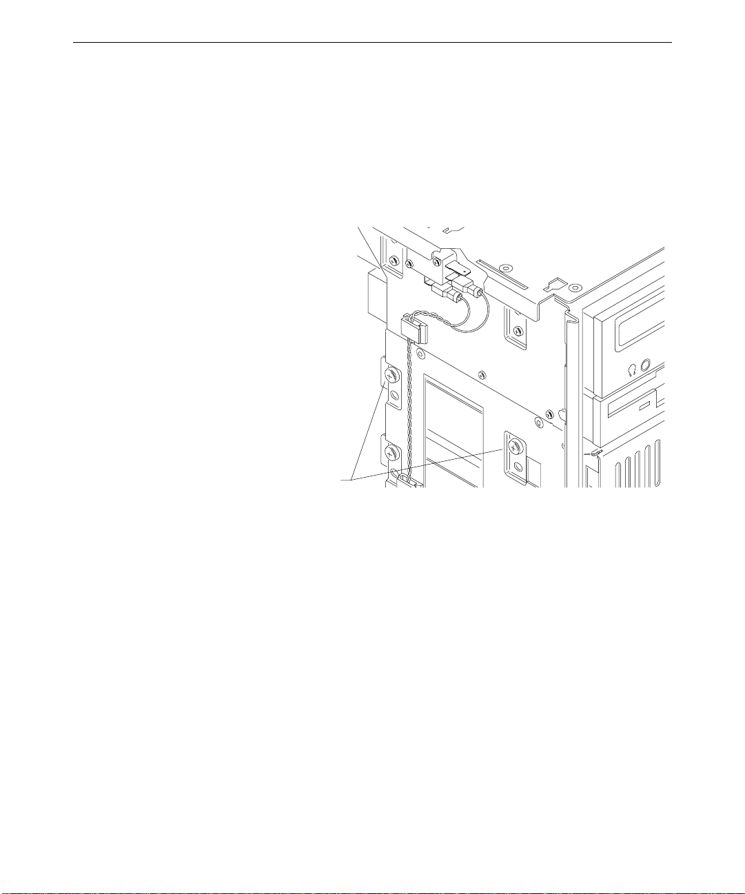
3. Remove the knurled retaining/grounding screw just below the top system fan on the rear
of the chassis.
4. Grasp both knurled plungers on the power supply, pull them toward each other, and
then swing the power supply toward you.
Page 13
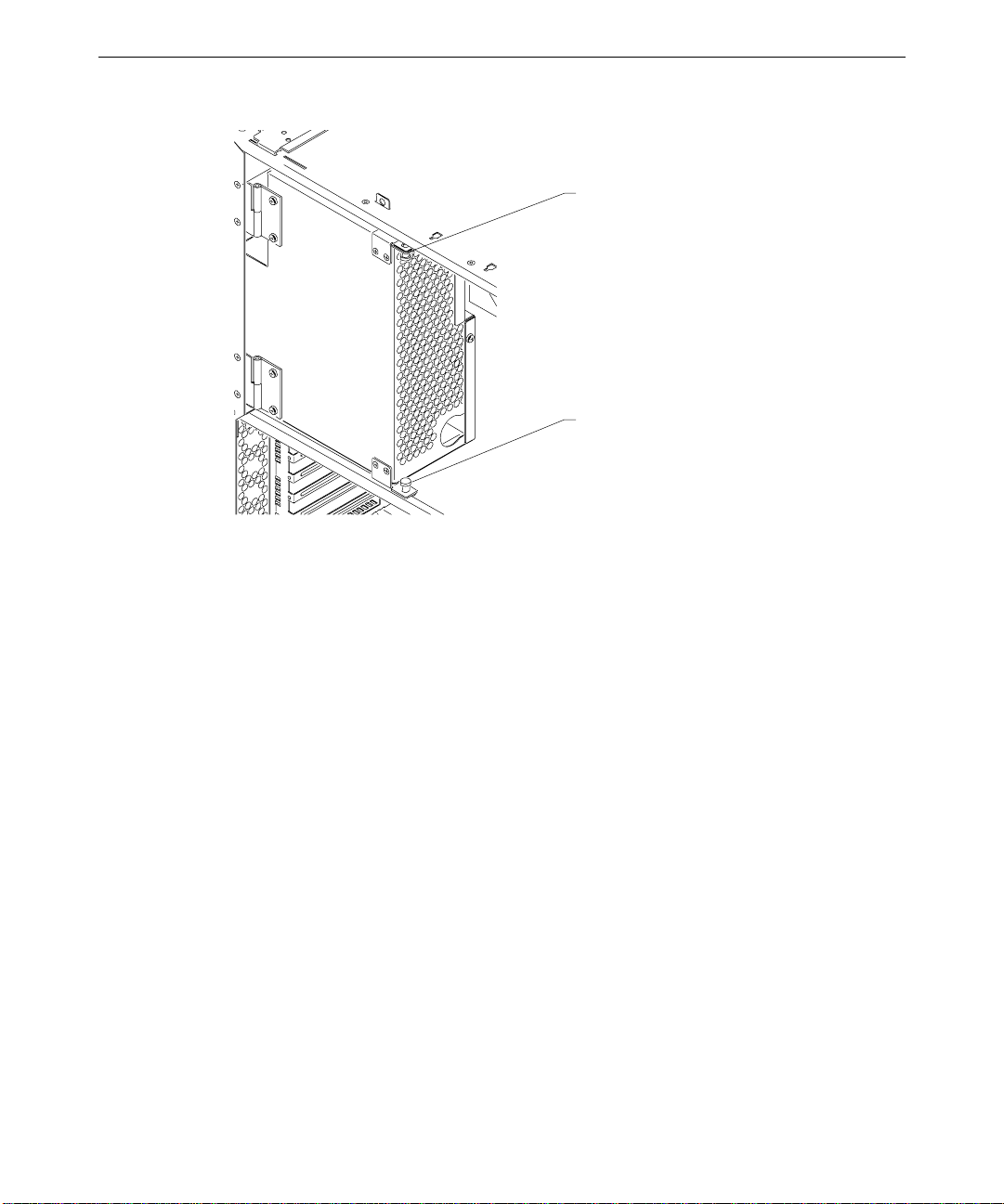
Top plunger
Bottom plunger
NOTE Disconnect power cables to internal devices as needed to allow the power supply to swing out
fully.
5
5. Access the exposed components as needed.
To stow the power supply:
1. Reconnect any power cables that you disconnected.
2. Grasp both knurled plungers, pull them toward each other, and then swing the power
supply away from you, back into the chassis.
CAUTION Carefully swing the power supply back into the chassis. Avoid pinching cables. Hold the
external SCSI cable against the chassis brace or rearrange cables slightly while swinging the
power supply into the chassis.
3. Align the plunger holes and release both plungers.
4. Install the retaining/grounding screw on the rear panel.
5. Install the left side panel and top cover.
6. Plug the AC power cord into its connector on the rear of the chassis.
Page 14

6
Page 15

2 Servicing the System
This chapter describes how to replace the standard parts within the system. Obey all
warning and caution labels while replacing parts.
Note that internal parts servicing procedures assume you have removed the left side panel
from the system. After you have finished servicing the system, replace panels as described in
Chapter 1, “Accessing the System.”
System Illustrations........................................................................................................8
Case Components ........................................................................................................11
Peripheral Drives.........................................................................................................15
Floppy Disk Drive.......................................................................................... 15
CD-ROM Drive..............................................................................................16
External Bay Disk Drives............................................................................... 17
Internal Bay Disk Drives................................................................................18
External SCSI Terminator ...........................................................................................20
Power Supply...............................................................................................................21
Bus Termination Card .................................................................................................23
Processor Module.........................................................................................................23
Voltage Regulator Module (VRM)...............................................................................24
DIMMs........................................................................................................................25
System Board...............................................................................................................25
Expansion Cards.......................................................................................................... 27
Fans.............................................................................................................................27
Chassis Intrusion Alarm Switch ...................................................................................29
Lithium (CMOS/Clock) Battery................................................................................... 30
LEDs, Light Pipe, and Standby Switch......................................................................... 30
7
Page 16
8
System Illustrations
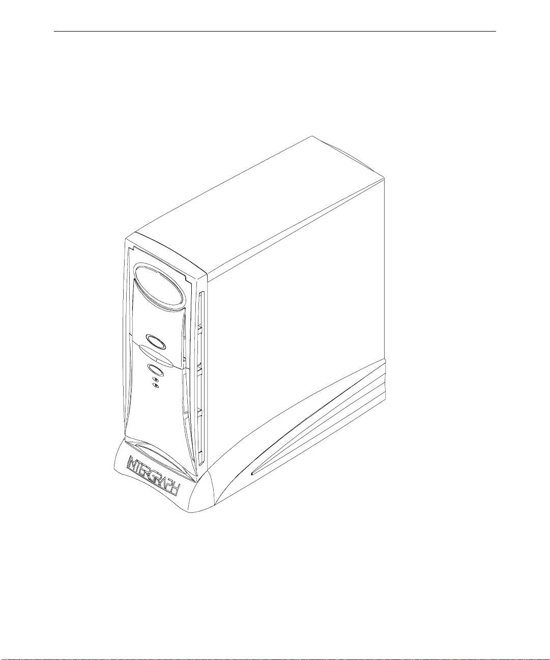
The illustrations show various external and internal views of the system. The front, right
view below depicts the system with all covers in place.
Page 17
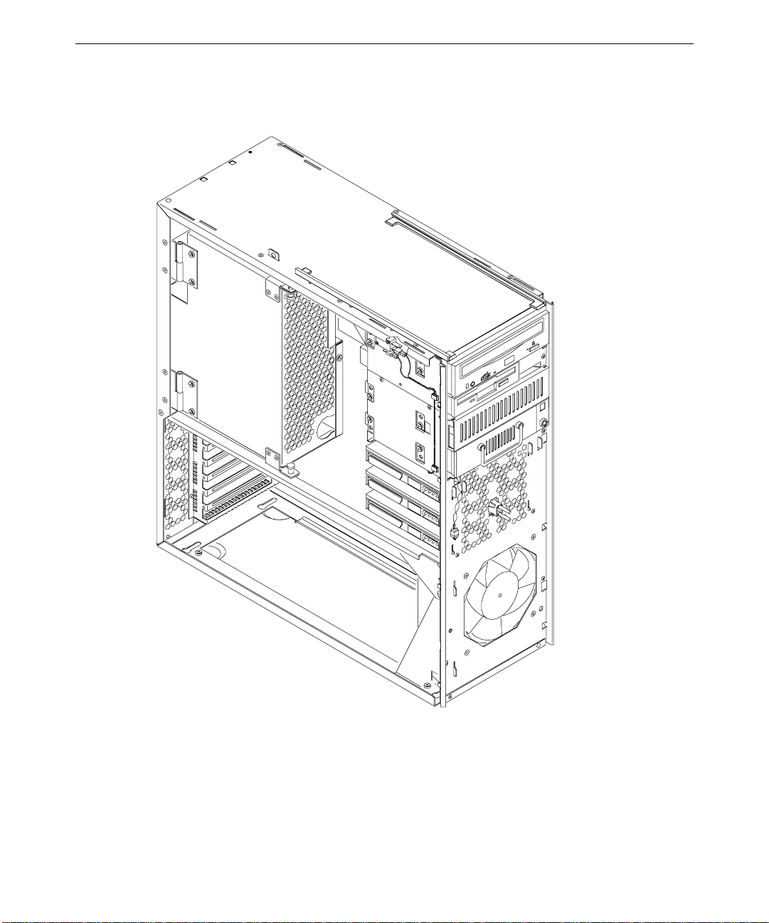
The front, left view below depicts the major parts of the system. Covers, cables, system
board and expansion cards are not shown.
9
Page 18
10
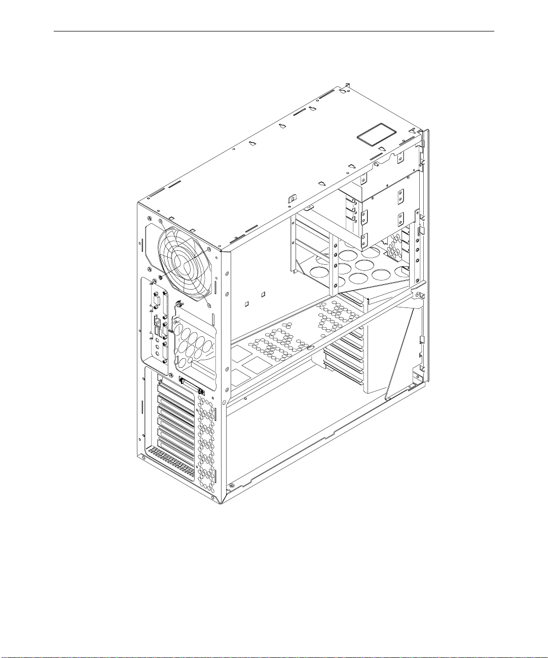
The back, left view below depicts the chassis with all major components removed.
Page 19

Case Components
Ordinarily you will not need to replace any of the external case components unless they are
broken or cosmetically damaged. All case components are designed for durability, but the
item that may require replacement first is the door and hinge assembly.
WARNING Disconnect the system from AC power before servicing internal components! Failure
to remove AC power may result in equipment damage or personal injury.
NOTE See Chapter 1, “Accessing the System,” for instructions on opening the system and
protecting against electrostatic discharge.
CAUTION Follow all warnings and cautions in servicing instructions. If you fail to follow documented,
approved procedures, personal injury or damage to equipment can result.
CAUTION Use an antistatic wrist strap for all servicing procedures to avoid the possibility of
electrostatic discharge.
CAUTION Do not overtighten screws and other fasteners to avoid damaging threads.
To replace the hinge or door, you must first remove the top cover. To replace the face panel,
you must remove the top cover and the door.
11
To replace the top cover:
1. Remove the top cover. See Chapter 1, “Accessing the System,” for details.
2. Install the new cover.
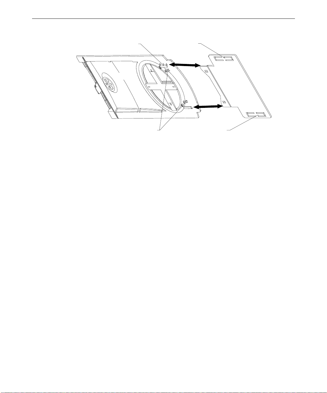
To replace the door assembly:
1. Remove the top cover. See Chapter 1, “Accessing the System,” for details.
2. Lift the door and hold it at a 90-degree angle from the face panel.
3. Insert a small flat-blade screwdriver between the door and hinge, near one of the square
holes on the underside of the door.
Page 20
12
Guide slot (1 per side)
Door
Locking tabs
Stop tabs
Hinge
Stop tabs
4. Pull the door toward you and pry the hinge and door apart until one side of the door
releases from its locking tab.
5. Repeat steps 3 and 4 for the other side of the door hinge.
6. Remove the door.
7. Do both of the following on the underside of the door:
−
Spread the release tabs on the large emblem and remove it
−
Squeeze the release tabs on the small emblem and remove it
8. Slide the hinge toward the front of the chassis until it stops.
9. Use a flat-blade screwdriver and pry each of the stop tabs on the hinge until the hinge
releases from the rails.
10. Orient the new hinge so that the locking tabs face down and insert the new hinge into
the track and push it forward until it stops.
11. Hold the hinge, align the beveled edges of the hinge with the guide slots on the door,
and push the door firmly onto the hinge until it snaps into place.
12. Press the two emblems onto the door until they snap into place.
13. Operate the door to test its movement.
14. Install the top cover. See Chapter 1, “Accessing the System,” for details.
To replace the hinge rails:
1. Remove the door. See the procedure above for details.
2. Slide the hinge toward the front of the chassis until it stops.
Page 21
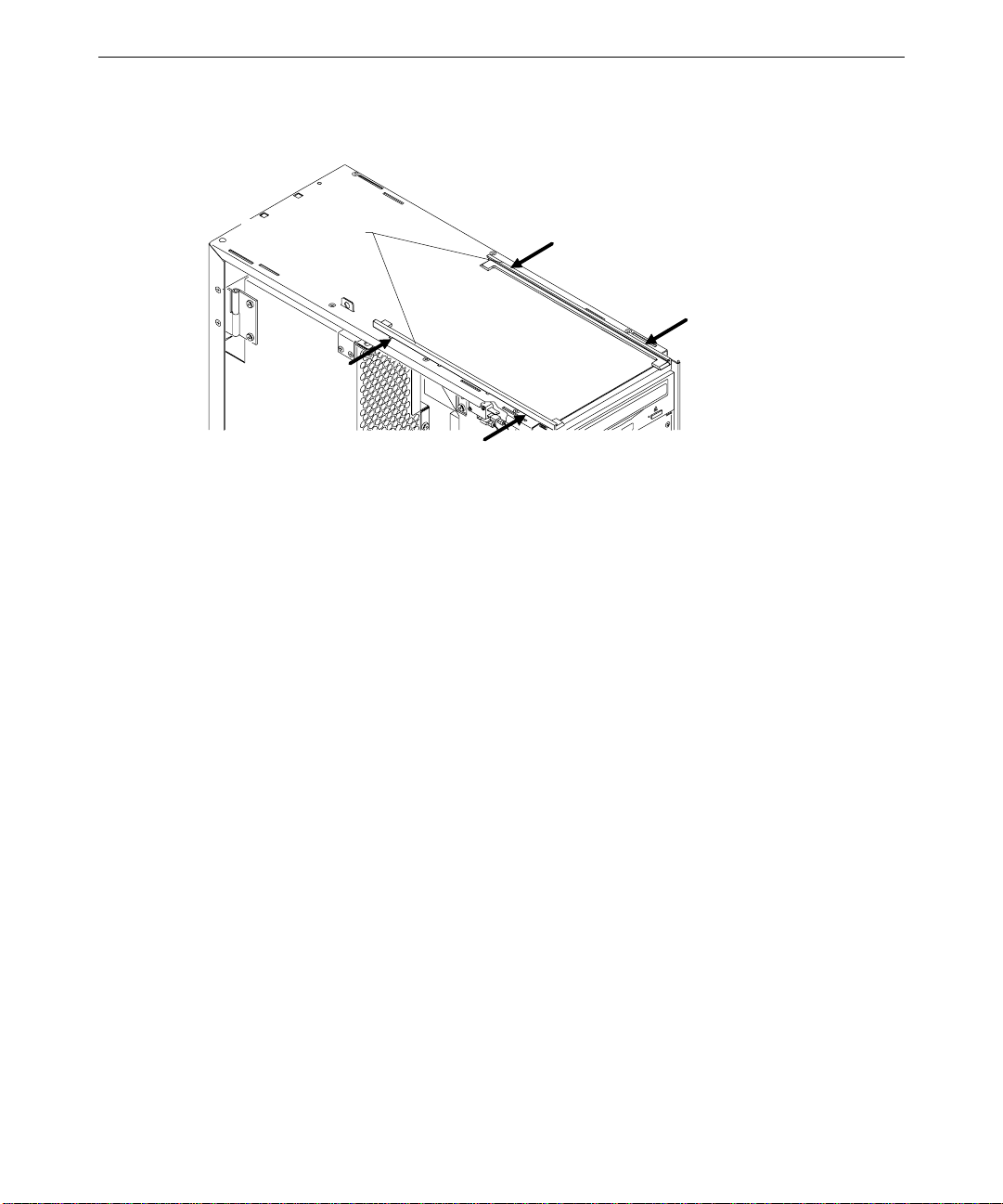
3. Use a flat-blade screwdriver and pry each of the stop tabs on the hinge until the hinge
releases from the rails.
Hinge rails
4. Remove the hinge from the rail.
5. Press a hinge rail toward the middle of the chassis until all four tabs release.
6. Lift the hinge rail off the chassis.
7. Orient the new hinge rail the same way as the one you removed, place the tabs in the
slots, and press outward until the rail snaps into place.
13
8. From the front of the chassis, slide the hinge into the rails.
To replace the face panel:
1. Remove the top cover and both side panels. See Chapter 1, “Accessing the System,” for
details.
2. Remove the door. See the “To replace the door assembly” procedure above for details.
3. Push the hinge back, away from the front of the chassis.
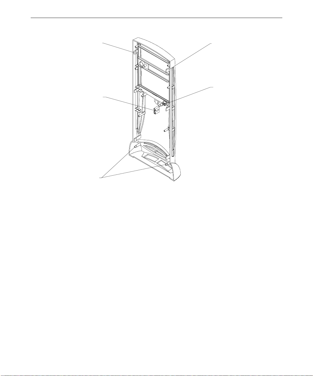
4. Use a flat-blade screwdriver to gently pry and release each of the plastic tabs on both
sides of the chassis. The tabs on the right side of the chassis are recessed. First release
the bottom tabs, release the middle tabs, and then release the top tabs.
CAUTION Release the tabs with care. Do not apply more pressure than necessary.
Page 22
14
Tab
(3 per side)
Light pipe gui des
Standoff pos t s
(4 per si d e)
Tab
(3 per side)
Standb y sw i tch
5. Pull the face panel away from the chassis slightly to ensure all tabs are released.
6. Grasp the left side of the face panel and pivot it left to expose the standby switch and
cable.
7. Spread the switch mount locking tabs, grasp the switch, and pull the switch out of its
mount.
8. Turn the face panel downward until the standby switch button drops out.
9. Place the left side of the new face panel near the left, front of the chassis and orient the
switch so that the black and green wires are at the bottom.
10. Push the standby switch into the mount until it snaps into place.
11. Place the standby switch button into its hole and push firmly until it seats.
12. Align the new face panel with the tab notches and light pipe guides, and carefully push
the panel onto the chassis until all tabs engage.
13. Install the door, left and right side panels, and top cover.
To replace the left or right side plastic cowling:
1. Remove the top cover, then remove the side panel that has the plastic you want to
replace. See Chapter 1, “Accessing the System,” for details.
2. Place the side panel, with the cowling side down, on a flat, padded surface.
Page 23
3. Remove the screw that secures the plastic to the side panel.
4. Grasp one side of the panel, press the release tabs, and lift the panel off the plastic.
5. Turn the side panel over and press the new plastic onto the panel until the release tabs
engage.
6. Turn the side panel over and install the screw.
7. Install the side panel onto the chassis.
8. Install the top cover. See Chapter 1, “Accessing the System,” for details.
Peripheral Drives
This section explains how to replace the floppy, CD-ROM, and internal and external bay
disk drives. See Chapter 6, “Peripherals,” for details on drive configuration and cables.
Floppy Disk Drive
To replace the floppy disk drive:
1. Disconnect the power cable and data cable from the drive. Note the position of the red
stripe on the data cable.
15
2. Remove the two screws that secure the floppy drive to the chassis. See the following
figure.
CD-ROM mounting
screws
Floppy drive mounting
screws
Page 24
16
3. From inside the chassis, push the back of the floppy drive until the bezel clears the
chassis, and slide the device out.
4. Slide the new floppy drive into the chassis and align the mounting holes.
5. Install the two mounting screws.
6. Connect the data cable and the power cable.
CD-ROM Drive
The procedure for replacing a SCSI or an EIDE CD-ROM drive is the same, except for data
cables and jumper settings.
To replace the CD-ROM drive:
1. Disconnect the power cable, data cable, and audio cable from the CD-ROM drive.
2. Remove the screws that secure the CD-ROM drive to the chassis. See the previous
figure.
3. From inside the chassis, push the back of the CD-ROM until the bezel clears the chassis,
then slide the device out.
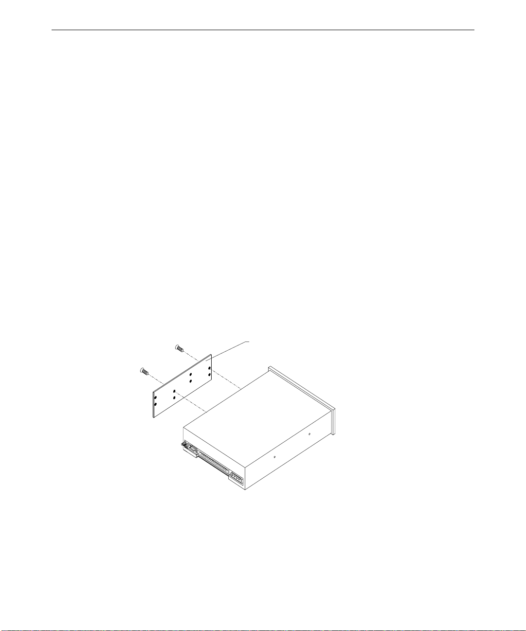
4. Remove the mounting guide from the right side of the CD-ROM. See the following
figure.
Mounting guide
5. Note the jumper settings on the rear of the CD-ROM.
6. Do one of the following on the new CD-ROM:
−
Set the EIDE master/slave jumper to the same position (Master) as the old drive if
you are installing an EIDE drive
Page 25
−
Set the SCSI ID jumper to the same address as the old drive if you are installing a
SCSI drive
7. Install the mounting guide on the right side of the new CD-ROM.
8. Slide the new CD-ROM drive into the chassis and align the mounting holes.
9. Install the screws that secure the CD-ROM to the chassis.
10. Connect the audio cable, data cable, and power cable.
External Bay Disk Drives
If a Kingston or other brand of removable disk module is installed in the external bay, see
the vendor documentation for disk drive and module replacement instructions.
To replace an external bay disk drive:
1. Disconnect the SCSI cable and power cable from the disk drive.
2. Remove the two screws that secure the external bay disk drive tray to the chassis. See
the following figure.
17
External bay mounting screws
3. From inside the chassis, push the tray out of the external bay, grasp the front of the tray,
and then slide it out of the bay.
4. Remove the screws that secure the disk drive to the tray and remove the drive.
5. Do all of the following:
−
Note the SCSI ID jumper settings on the old drive
−
Set the SCSI ID on the new drive to the same ID as the old drive
Page 26
18
−
Disable termination on the new drive
See Chapter 6, “Peripherals,” for details on these tasks.
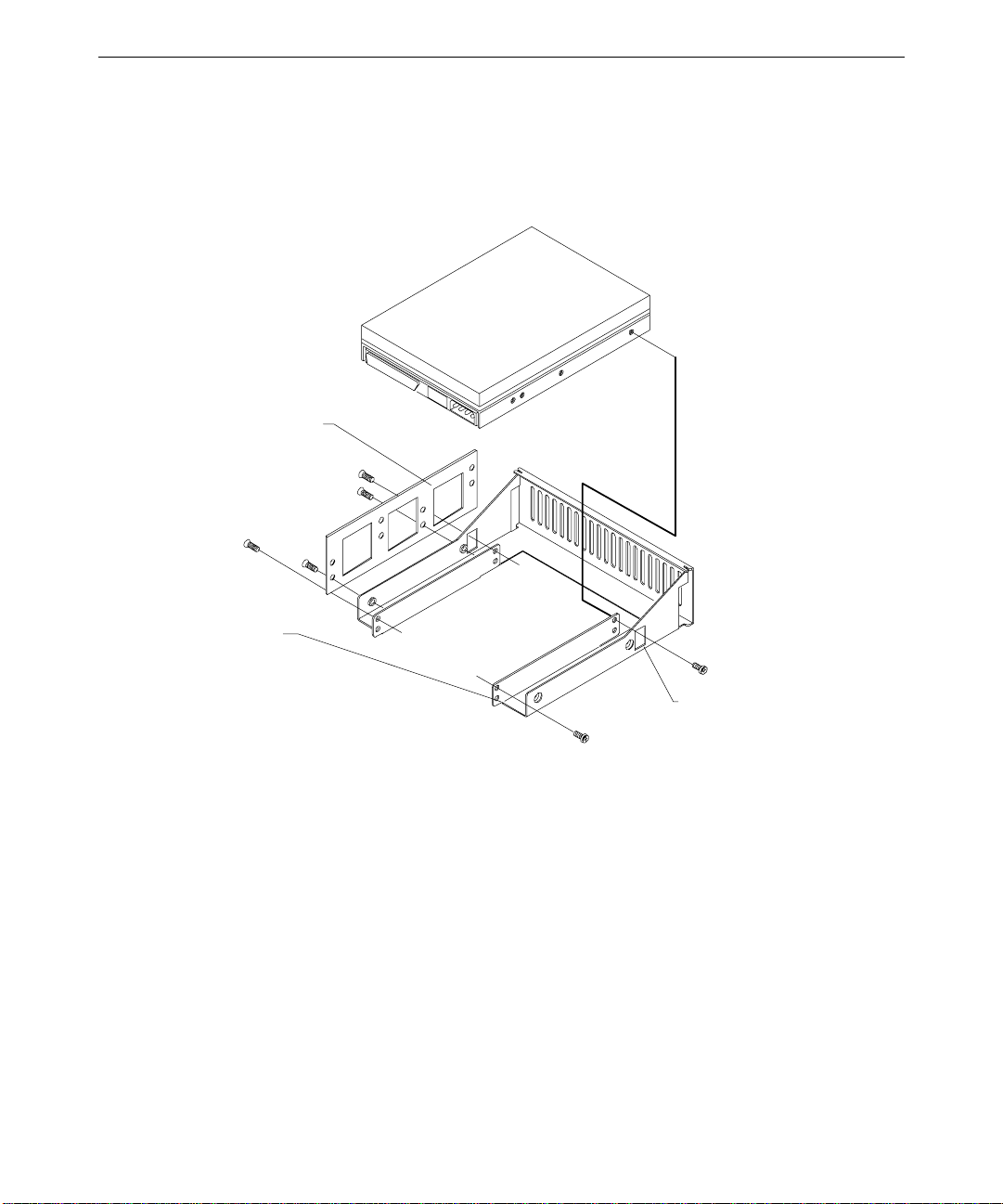
6. Place the disk drive in the tray, align the mounting holes, and install the mounting
screws that secure the disk drive to the tray. See the following figure.
Mounti ng guide
Drive
7. Slide the tray assembly into the chassis and align the mounting holes.
8. Install the screws that secure the tray to the chassis.
9. Connect the SCSI cable and the power cable to the disk drive.
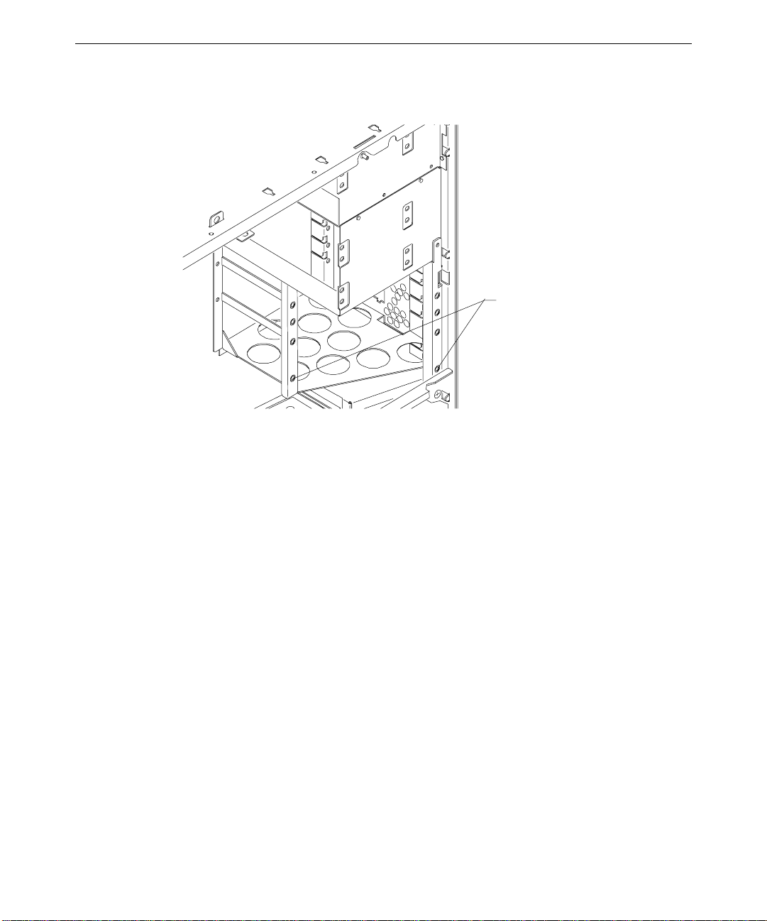
Internal Bay Disk Drives
To replace an internal bay disk drive:
1. Remove the right and left covers. See Chapter 1, “Accessing the System,” for details.
2. Disconnect the SCSI cable and power cable from the disk drive.
3. Remove the two screws that secure the drive bracket assembly to the left side of the
chassis.
Access hole (2)
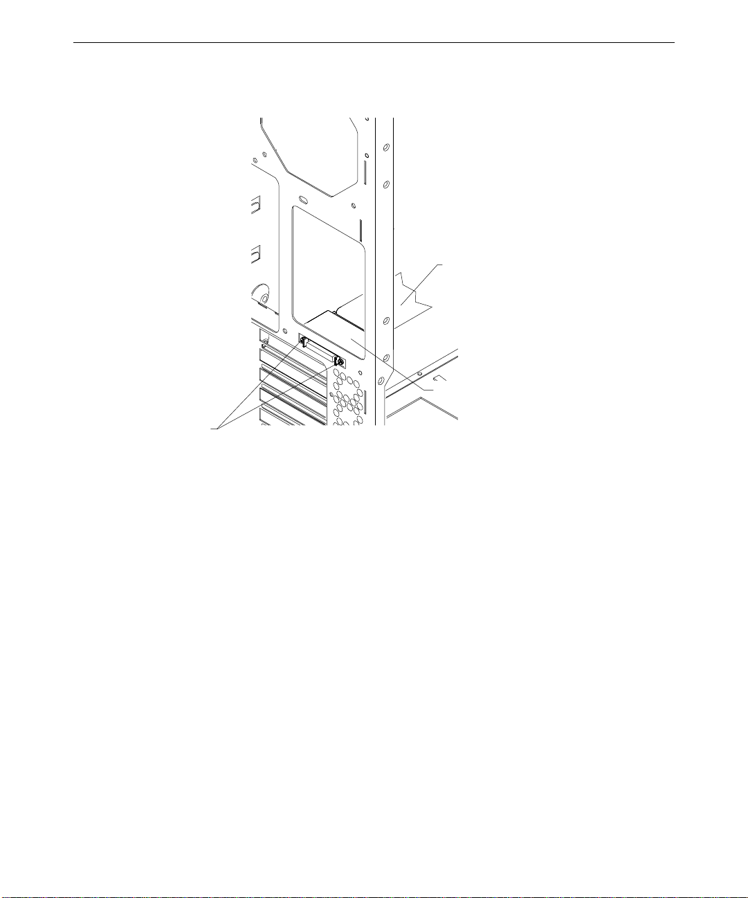
Page 27
4. Grasp the drive bracket assembly and remove the screw that secures the bracket to the
right side of the chassis.
5. Pull the drive bracket assembly out of the chassis.
6. Remove the four screws that secure the old drive to the bracket.
7. Do all of the following:
−
Note the SCSI ID jumper settings on the old drive
−
Set the SCSI ID on the new drive to the same ID as the old drive
−
Disable termination on the new drive
See Chapter 6, “Peripherals,” for details on these tasks.
8. Install the new drive on the bracket.
19
Alignment tabs
Rear mounting tab
Front mounting tabs
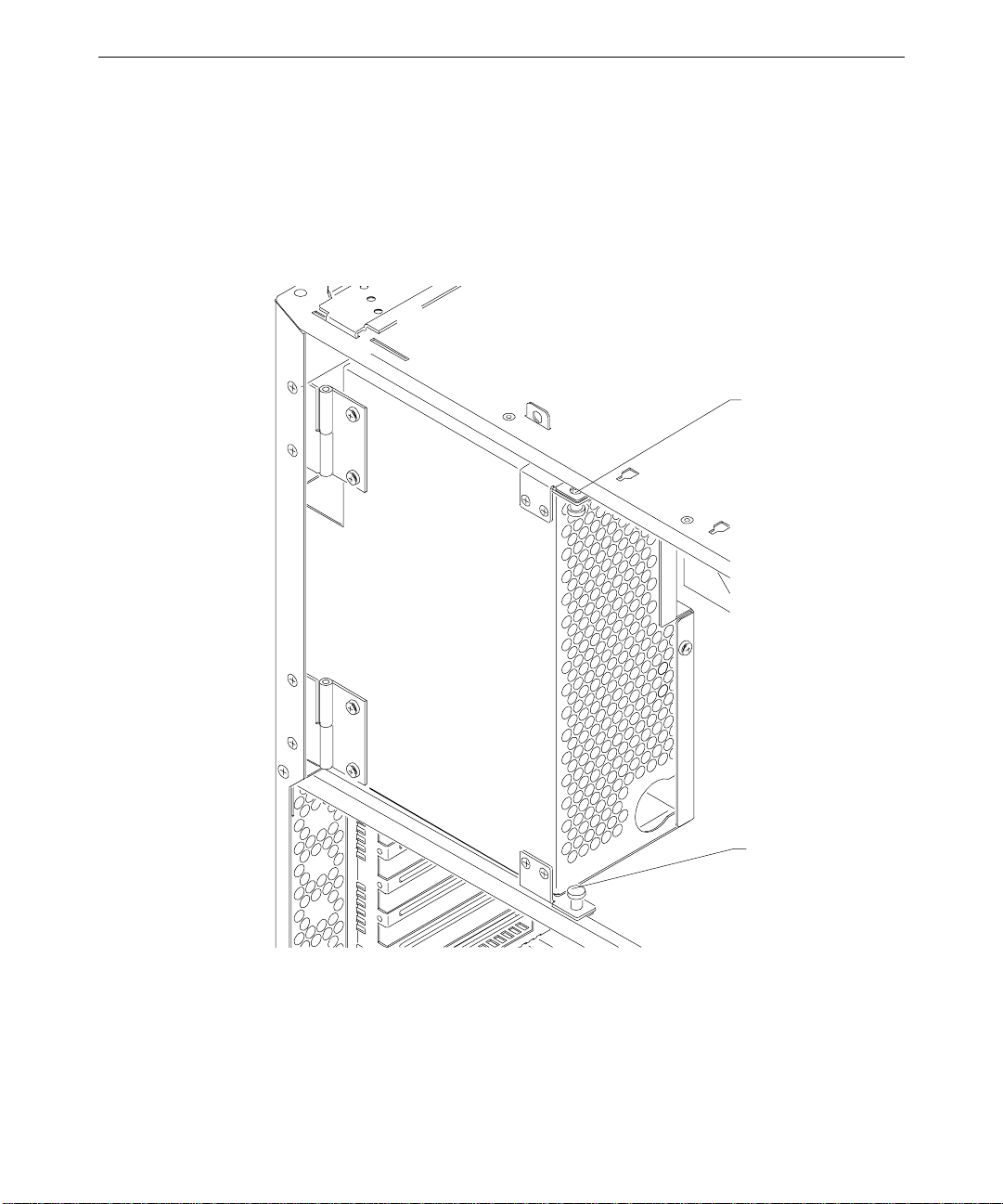
Page 28
20
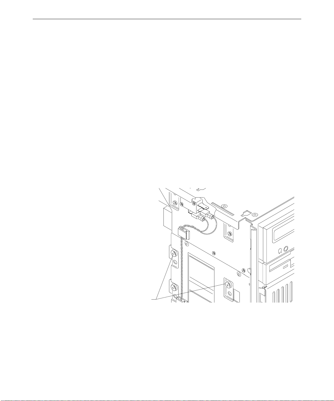
9. Insert the alignment tabs into the appropriate slots in the chassis.
Screw holes for front moun ting tabs
10. Install the two screws that secure the drive bracket assembly front mounting tabs to the
chassis.
11. Install the screw that secures the drive bracket assembly to the right side of the chassis.
12. Install the right side panel.
13. Connect the SCSI cable and the power cable to the new drive.
External SCSI Terminator
The connector for the external SCSI terminator board, MSMT283, is mounted on the rear of
the chassis just below the power supply. MSMT283 provides active termination for the
system end of the external Ultra SCSI bus. Cable MCBL253A connects the terminator to
J44 on the system board. See the system board diagram in Chapter 5, “System Board,” for
connector and socket locations.
To replace the external Ultra SCSI terminator board:
1. Swing the power supply out of the chassis. See Chapter 1, “Accessing the System,” for
details.
2. Unfasten the reusable wire tie that secures the power supply cable bundle.
3. Lift the power supply off its hinge pins and place it aside carefully.
Page 29
4. Disconnect the SCSI cable (MCBL253A) from the terminator board. See the following
figure.
SCSI cable (to J44)
Term in ator board
Screws (2)
21
5. Remove the two small screws that secure the connector to the rear of the chassis.
6. Note the orientation of the terminator board and remove it from inside the chassis.
7. Orient the new terminator board component side down, align the mounting holes of the
new terminator with the chassis mounting holes, and install the two screws.
8. Connect the SCSI cable to the terminator.
9. Place the power supply on its hinge pins and fasten the wire tie on the cable bundle.
10. Swing the power supply back into the chassis and secure it with the plungers.
Power Supply
See Chapter 7, “Power Supply, Fans, and Hardware Monitoring Devices,” for details on the
power supply.
To replace the power supply:
1. Unplug the AC power cord from the rear of the unit.
2. Note the location of all power cable connectors on the system board and peripheral
devices.
Page 30
22
3. Disconnect all power cables from all internal devices and the system board.
4. Place the power supply cable bundle outside the chassis.
5. Remove the knurled retaining/grounding screw on the back of the system. This fastener
is located between the top fan and the power supply fan.
6. Grasp and pull the power supply plungers toward each other, and then swing the power
supply out from the chassis.
Top plunger
Bottom plunger
7. Swing the power supply out sufficiently to avoid interference from the chassis or the top
system fan.
8. Lift the power supply off its hinges and set it aside.
9. If the new power supply does not have hinges and plungers, remove them from the old
supply and install them on the new power supply.
Page 31

10. Place the new power supply on the hinge pins.
11. Connect the power cables to the system board and internal devices. See Chapter 7,
“Power Supply, Fans, and Hardware Monitoring Devices,” for connection details.
12. Grasp and pull the plungers toward each other, swing the power supply back into the
chassis, and secure it with the plungers.
CAUTION Carefully swing the power supply back into the chassis. Avoid pinching cables. Hold the
external SCSI cable against the chassis brace or rearrange cables slightly while swinging the
power supply into the chassis.
13. Install the retaining/grounding screw on the back of the chassis.
14. Plug the AC power cord into its connector on the back of the chassis.
Bus Termination Card
The bus termination card, MSMT379, is used only in systems with one processor. The card
provides termination for the processor bus. Single-processor systems will not operate
without the card installed. See the system board diagram in Chapter 5, “System Board,” for
connector and socket locations.
23
To replace the bus termination card:
1. Swing the power supply out of the chassis. See Chapter 1, “Accessing the System,” for
details.
2. Locate the bus termination card at J8, just below the primary CPU.
3. Note the orientation of the card.
4. Grasp the top edge of the card at each end, and pull it straight out.
5. Remove the new card from its antistatic package, orient the card component side up, and
insert the card in the slot.
6. Press down firmly until the card is seated.
7. Swing the power supply back into the chassis and secure it with the plungers.
Processor Module
The replacement Pentium II 300 MHz processor, CICM452, is housed in a plastic module
with heat sinks. The bottom right heat sink fin is removed to provide clearance for the fan
connector on the Revision A system board. The processor module mounts in the dual
processor retention module (DPRM). See the system board diagram in Chapter 5, “System
Board,” for connector and socket locations.
Page 32

24
CAUTION To avoid damaging the system board, ensure that your replacement processor has the
bottom, right heat sink fin removed.
To replace the processor module:
1. Swing the power supply out of the chassis to expose the processor. See Chapter 1,
“Accessing the System,” for details.
2. Press the locking tabs on the top corners of the processor module inward, towards each
other, until they click into the release position.
3. Slide the processor module out of the DPRM.
4. Remove the new processor from its antistatic package, and align the processor module
over the DPRM. The processor module is keyed and fits only one way.
5. Press the processor module down until it seats.
6. Press the processor module locking tabs outward until they click into the locked
position.
7. Swing the power supply back into the chassis and secure it with the plungers.
Voltage Regulator Module (VRM)
The voltage regulator module (VRM), CPWS165, is used only in dual-processor systems.
The VRM is located at J10, just below the secondary processor. See the system board
diagram in Chapter 5, “System Board,” for connector and socket locations.
You may want to remove the secondary processor to provide better access before replacing
the VRM.
To replace the VRM:
1. Swing the power supply out of the chassis to expose the VRM. See Chapter 1,
“Accessing the System,” for details.
2. Grasp the top of the VRM with one hand, and use your forefinger and middle finger of
the other hand to push the release tabs up, toward the processor.
3. Keep pushing the release tabs and pull the VRM out of its socket.
4. Remove the new VRM from its antistatic package, and align it over the slot.
5. Press the VRM into the slot until the release tabs click.
6. Swing the power supply back into the chassis and secure it with the plungers.
Page 33

DIMMs
25
See the section, “Adding Memory,” in Chapter 3, “Upgrading the System,” for important
details on handling DIMMs. The DIMM sockets are located just above the power connectors
P1 and P2 on the system board. See the system board diagram in Chapter 5, “System
Board,” for connector and socket locations.
To replace a DIMM:
1. Swing the power supply out to expose the DIMM sockets. See Chapter 1, “Accessing the
System,” for details.
2. Press the release tabs outward, away from each other.
3. Grasp the top edge of the DIMM and pull it out of the socket.
4. Remove the new DIMM from the antistatic package.
5. Orient the DIMM so that the notches match the keys in the socket.
DIMM
6. Insert the DIMM at a 90-degree angle into the socket.
7. Push gently straight down until the release tabs snap into place.
8. Swing the power supply back into the unit and secure it with the plungers.
System Board
You must swap the DIMMs, bus termination card (if installed), VRM (if installed), and
processor module(s) from the old system board to the new one. See the system board
diagram in Chapter 5, “System Board,” for connector and socket locations.
Note that a number of Fastex fasteners are mounted in the right side of the chassis to secure
the system board and dual processor retention module (DPRM) supports. Do not overtighten
the screws to these fasteners. If overtightened, the fasteners may distort.
Release Tab
Notch
DIMM socket
Page 34

26
Hole in right side of chassis
Fastex fastener
To remove the system board:
1. Remove the top cover and both side panels. See Chapter 1, “Accessing the System,” for
details.
2. Remove the power supply. See the “Power Supply” section above for details.
3. Lay the chassis down on its right side.
4. Note the locations where all cables are connected to the system board.
5. Disconnect all cables from the system board.
6. Note the locations of the expansion cards, remove them, and place the cards on an
antistatic surface.
7. Remove DIMMs, the bus termination card (if installed), VRM (if installed), and
processor module(s) and place them on an antistatic surface. See the respective
procedures above for details on removing these components.
8. Remove the chassis brace.
9. Remove the jackscrews on all external port connectors.
WARNING Use care when removing or installing the screws to avoid damaging components on
the system board.
10. Remove the four screws and the four plastic rivets on the dual processor retention
module (DPRM), and remove the DPRM from the chassis.
11. Remove the 21 screws from the system board.
12. Lift the system board out of the chassis and place it on an antistatic surface.
To install a new system board:
1. Place the new system board into the chassis, align all mounting holes, and install the
jackscrews on the external port connectors.
2. Loosely install the remaining screws on the system board, except those for the DPRM.
Do not tighten the screws yet.
3. Mount the DPRM to the system board with the plastic rivets. The DPRM is keyed to the
processor slots to ensure correct orientation.
Page 35

4. Tighten all fasteners that secure the system board and DPRM to the chassis. You may
need to adjust the Fastex fasteners slightly on the right side of the chassis.
5. Install the chassis brace.
6. Install the DIMMs, processor(s), VRM (if used), and bus termination card (if used) on
the system board.
7. Install the expansion cards back into their original slots.
8. Connect the internal cables to the system board. If you need help identifying cable
connections, see Chapter 5, “System Board.”
9. Place the power supply on its hinge pins, swing it back into the chassis, and secure it
with the plungers.
10. Install the power supply retaining/grounding screw on the rear of the chassis.
11. Install the right and left side panels, and then install the top cover.
Expansion Cards
See the system board diagram in Chapter 5, “System Board,” for connector and socket
locations.
27
Fans
To replace an expansion card:
1. Disconnect the external device attached to the expansion card connector on the rear of
the system.
2. Disconnect any internal cable that connects the card to another device (if installed), such
as a geometry board.
3. Remove the screw that secures the card to the left card guide.
4. Pull the expansion card straight out, and place it on an antistatic surface.
5. Slide the new card into the same slot from which you removed the old card.
6. Install the screw that secures the card to the left card guide.
7. Connect any cables from other internal devices, if installed.
8. Connect the external device to the expansion card connector on the rear of the system.
See Chapter 7, “Power Supply, Fans, and Hardware Monitoring Devices,” for details on fans.
Page 36

28
NOTE Arrows on the fan indicate airflow direction and rotation. Ensure system fans are installed
with the airflow direction arrow pointing in the correct direction.
To replace the top system fan:
1. Remove the power supply. See the “Power Supply” section above for details.
2. Remove the primary processor and the secondary processor (if installed). See the “To
replace the processor module” procedure above for details.
3. Disconnect the fan power cable from J5, which is located near the top left of the
secondary processor slot on the system board.
4. Remove the four screws securing the grille and fan to the chassis.
5. Gently pull the fan right until the motor housing contacts the DPRM.
6. Gently pull the fan downward until the fan housing clears the chassis and remove the
fan.
7. Note the airflow direction of the fan and the position of the fan cable.
8. Ensure the airflow direction arrow on the new fan is pointing in the correct direction,
then place the new fan at an angle inside the chassis.
9. Grasp the fan with one hand and use the other to slightly pull the left side of the DPRM
toward the right so that the fan slips into place.
10. Place the grille on the outside, align the mounting holes, and install the four screws. Do
not overtighten.
11. Connect the fan power cable to J5.
12. Install the processor module(s).
13. Install the power supply, swing it back into the chassis, and secure it with the plungers.
To replace the bottom system fan:
1. Remove the face panel. See the “Case Components” section above for details.
2. Remove the expansion cards. See the “Expansion Cards” section above for details.
3. Remove the two screws that secure the right card guide to the chassis.
4. Lift the card guide up to disengage the mounting tabs, and remove it from the chassis.
5. Disconnect the fan power cable from J54, which is located near the battery on the front
edge of the system board.
6. Note the airflow direction of the fan.
7. Remove the four screws securing the fan to the front of the chassis and remove the fan.
Page 37

8. Ensure that the airflow direction arrow on the new fan is pointing in the correct
direction and place the fan inside the chassis.
9. Align the mounting holes, and install the four screws. Do not overtighten.
10. Connect the fan power cable to J54.
11. Insert the card guide tabs into the slots and push the card guide down until the tabs
engage.
12. Install the two screws that secure the card guide to the chassis.
13. Install the expansion cards.
14. Install the face panel.
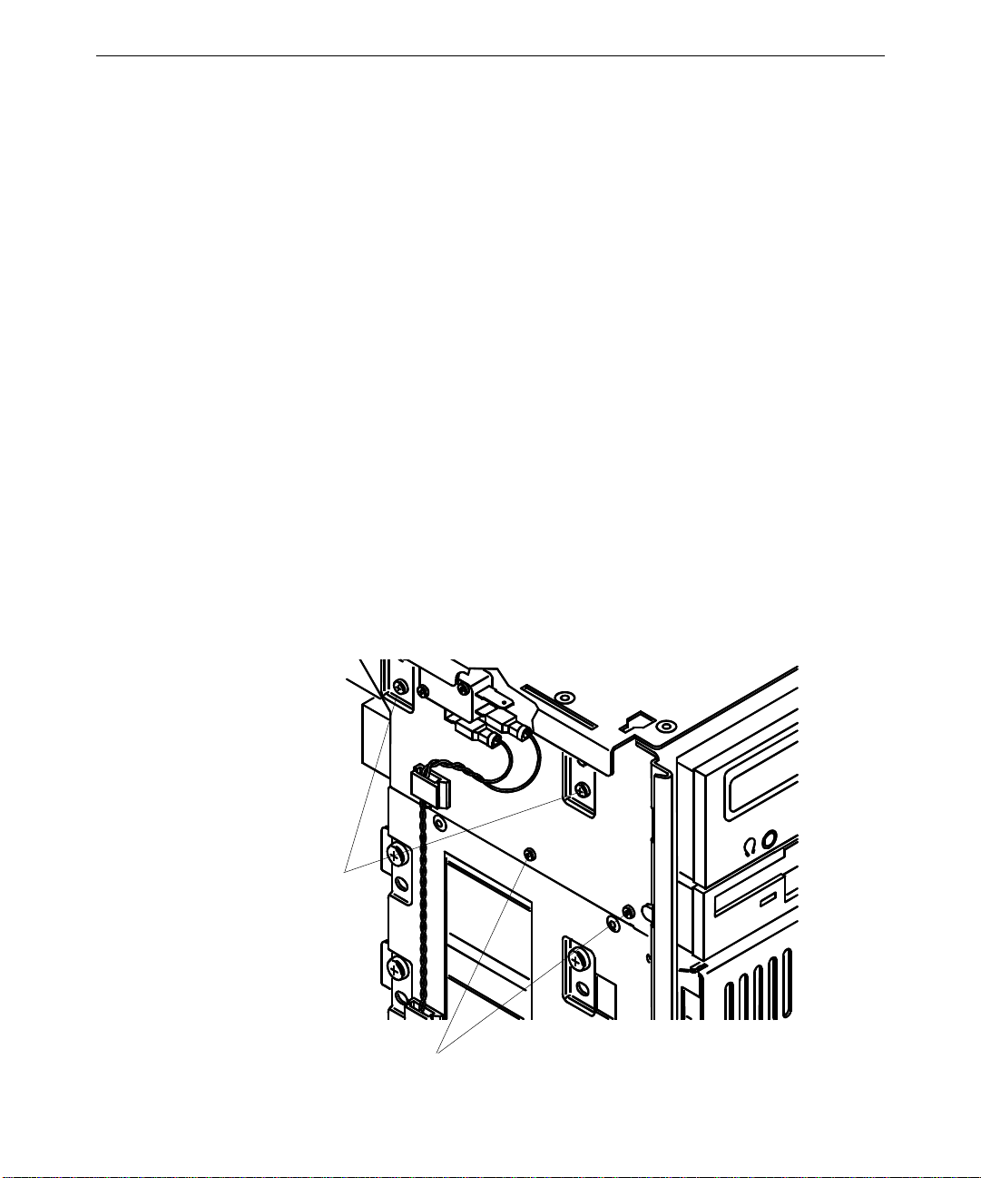
Chassis Intrusion Alarm Switch
The chassis intrusion alarm switch (CWSX30800) has three connectors. Only the bottom
two connectors are used. See the system board diagram in Chapter 5, “System Board,” for
connector and socket locations.
To replace the chassis intrusion alarm switch:
29
1. Note where the red and black wires connect to the switch.
2. Disconnect the wires from the switch.
Alarm switch
3. Remove the two screws that secure the switch to the chassis and remove the switch.
Page 38

30
4. Align the new switch with the chassis mounting holes and install the screws.
5. Connect the black wire to the middle connector and connect the red wire to the bottom
connector.
Lithium (CMOS/Clock) Battery
The battery is located near the bottom front of the system board. See the system board
diagram in Chapter 5, “System Board,” for details.
After you remove the battery, the system will lose its operating parameters stored in CMOS.
As a result, the system BIOS parameters are lost. Parameters include date, time, hardware
configuration, and other data.
After you install the new battery, you must reset the date and time and reconfigure the BIOS.
See the TDZ 2000 System Setup for details on updating and configuring the BIOS.
WARNING There is a danger of explosion if the battery is incorrectly replaced.
WARNING Replace the battery with the same or equivalent type only, as recommended by the
battery manufacturer. Dispose of used batteries according to the battery
manufacturer’s instructions.
To replace the battery:
1. Remove any expansion cards that restrict access to the battery. See the “Expansion
Cards” above for details.
2. Note the positive orientation of the battery. Carefully remove the discharged battery by
grasping it firmly and pulling it out of the socket.
3. Install the new battery in the same orientation as the old battery.
4. Dispose of the battery according to the manufacturer’s instructions.
5. Install the expansion cards that you removed.
LEDs, Light Pipe, and Standby Switch
See the system board diagram in Chapter 5, “System Board,” for connector and socket
locations. See also the “Cable Routing and Pinouts” section in Chapter 5, “System Board,”
for LED and standby switch cable and connector details.
Page 39

To replace an LED:
1. Remove the internal bay disk drives. See the “Internal Bay Disk Drives” section for
details.
2. Note the locations of each of the three LEDs on the light pipe.
3. Remove the LED from its mount on the light pipe, then disconnect the LED cable from
its connector on the system board.
4. Remove the LED cable from the chassis.
5. Route the new LED cable through the chassis and connect it to the appropriate
connector on the system board.
6. Press the LED into its mount on the light pipe.
To replace the light pipe:
1. Remove the face panel. See the “Case Components” section above for details.
2. Remove the internal bay disk drives. See the “Internal Bay Disk Drives” section above
for details.
3. Disconnect the LEDs from the light pipe.
31
Green LED (power)
black/white wires
Yellow LED (power managed)
blue/bl ack w ire s
Green LED (disk activity)
black/orange wires
Top of chassis
4. Squeeze the mounting tabs on the light pipe inward and push the light pipe through its
mounting hole.
5. From inside the chassis, remove the light pipe.
6. Orient the new light pipe so that its twin LED mounts face up, and press the light pipe
through its mounting hole until it snaps into place.
7. Push each of the LEDs into its respective mount on the new light pipe.
8. Install the internal bay disk drives.
Page 40

32
9. Install the face panel.
To replace the standby switch:
1. Remove the face panel. See the “Case Components” section above for details.
2. Disconnect the standby switch cable connector from the system board.
3. Remove the switch cable from the chassis.
4. Insert the connector end of the switch cable through the cable access hole on the front of
the chassis and route the new switch cable through the chassis.
5. Connect the switch cable to the connector on the system board.
6. Press the switch into its mount on the face panel.
7. Install the face panel and the switch button.
Page 41

3 Upgrading the System
This chapter describes upgrading memory and processors, as well as installing expansion
cards, internal SCSI drives, and external SCSI drives.
Adding Memory...........................................................................................................34
Adding a Processor......................................................................................................36
Single-to-Dual Upgrade..................................................................................36
Adding Expansion Cards .............................................................................................37
Slot Locations................................................................................................38
Upgrading Graphics Cards .............................................................................39
Installing Expansion Cards ............................................................................40
Assigning System Resources.......................................................................... 40
Adding Internal SCSI Drives .......................................................................................41
Device Locations............................................................................................41
Installing Devices in the Drive Bays...............................................................43
Adding External SCSI Drives ......................................................................................46
SCSI Cable Length Guidelines.......................................................................47
SCSI Cable Quality Guidelines.......................................................................47
SCSI ID Guidelines........................................................................................47
SCSI Termination Guidelines for External Devices ........................................48
Connecting the Device ................................................................................... 48
Changing SCSI Host Adapter or Device Settings............................................48
33
Page 42

34
Adding Memory
You can upgrade memory on the MSMT401 system board in 64 MB or 128 MB increments.
The minimum total memory is 64 MB and the maximum total memory is 512 MB.
You can install DIMMs one at a time. Each bank has only one slot.
Memory upgrade kits from Intergraph Computer Systems contain one DIMM and a
disposable antistatic wrist strap.
WARNING Disconnect the system from AC power before servicing internal components! Failure
to remove AC power may result in equipment damage or personal injury.
NOTE See Chapter 1, “Accessing the System,” for instructions on opening the system and
protecting against electrostatic discharge.
CAUTION Follow all warnings and cautions in servicing instructions. If you fail to follow documented,
approved procedures, personal injury and damage to equipment can result.
CAUTION Use an antistatic wrist strap for all servicing procedures to avoid the possibility of
electrostatic discharge.
CAUTION Do not overtighten screws and other fasteners to avoid damaging threads.
CAUTION System memory modules from Intergraph Computer Systems are certified for use with
Intergraph computers at extremes of temperature and system load to ensure reliable
performance. System memory modules available from other vendors may not function
properly or reliably in your Intergraph computer.
To avoid damaging DIMMs and voiding the warranty, take the following precautions:
u
Do not touch the gold-plated finger contacts.
u
Do not install DIMMs that have tin-plated finger contacts.
u
Do not bend, twist, drop, or otherwise handle DIMMs carelessly.
u
Do not expose DIMMs to moisture or extreme temperatures.
u
Do not remove DIMMs from the antistatic bag until installation.
Before you install memory, do the following:
u
Inspect DIMM keying. The finger contacts on the DIMM must match the socket
configuration. This ensures that you have the correct voltage and type of DIMM.
u
Inspect DIMM contacts. The DIMM must have gold-plated fingers that match the goldplated socket contacts.
Page 43

Follow these population rules to correctly install the DIMMs:
u
Remember that you can install DIMMs one at a time.
u
Install DIMMs one bank at a time; begin with bank 0 or the first open bank; end with
bank 3.
u
Press the DIMM straight down into the socket. Do not rock the DIMM; apply even
pressure along the top edge of the DIMM.
u
Restart the computer after adding or replacing DIMMs. The computer detects the new
memory automatically.
The following table shows possible memory configurations. Each bank contains one socket.
NP designates the socket is not populated.
35
Memory
Bank 0 Bank 1 Bank 2 Bank 3
64 MB 64 MB NP NP NP
128 MB 64 MB 64 MB NP NP
128 MB NP NP NP
256 MB 64 MB 64 MB 64 MB 64 MB
64 MB 64 MB 128 MB NP
128 MB 128 MB NP NP
512 MB 128 MB 128 MB 128 MB 128 MB
Typical memory configurations include the following: 64 MB (one 8Mx72 DIMM); 128 MB
(one 16Mx72 DIMM); 256 MB (two 16Mx72 DIMMs); and 512 MB (four 16Mx72
DIMMs).
See the system board diagram in Chapter 5, “System Board,” for socket locations.
To install the memory upgrade:
1. Swing the power supply out to expose the DIMM sockets. See Chapter 1, “Accessing
the System,” for details.
2. Locate the available DIMM socket and ensure the release tabs are open.
3. Grasp the DIMM so that the notch positions match the keys in the socket. See the figure
in the section, “DIMMs,” in Chapter 2, “Servicing the System.”.
4. Insert the DIMM at a 90-degree angle into the socket.
5. Push gently straight down until the release tabs snap into place.
6. Swing the power supply back into the chassis and secure it with the plungers.
Page 44

36
Adding a Processor
You can upgrade a single processor system to a dual processor system. You can upgrade a
processor to a faster processor. You can install a processor module with heat sinks
(CICM452, Intergraph standard part) or a boxed processor module with integral fan (nonIntergraph part). The lower right heat sink fin on the Intergraph processor module is
removed to provide clearance for the fan connector at J5 on the MSMT401 Revision A
system board.
Processors are mounted in a dual processor retention module (DPRM), which surrounds the
processor slots. See the system board diagram in Chapter 5, “System Board,” for the
location of processor slots and related connectors.
Single-to-Dual Upgrade
You can upgrade to dual processors in the following ways:
u
You can purchase a TDZ 2000 single-to-dual processor upgrade kit (PUPG11906) from
Intergraph Computer Systems. The kit contains all the hardware, software, and
documentation required to perform the upgrade.
u
If you purchase a second processor from another vendor, you can purchase a Voltage
Regulator Module (VRM) from Intergraph Computer Systems.
After completing the hardware upgrade, you must also upgrade to a multi-processor version
of Windows NT. You can upgrade the operating system in the following ways:
u
You can purchase the Intergraph upgrade kit mentioned previously. The kit contains all
the hardware, software, and documentation required to perform the upgrade.
u
If you have or purchase a Windows NT 4.0 Workstation Resource Kit (ISBN 1-57231343-9), you can use software on the kit’s CD-ROM to upgrade Windows NT 4.0. The
files required for the upgrade are
u
While not recommended by Intergraph Computer Systems, you can back up all critical
UPTOMP.EXE , UPTOMP.INF, and UPTOMP.TXT.
system data, install the second processor and VRM, and reinstall Windows NT 4.0 to
load the required multi-processor Hardware Abstraction Layer (HAL).
NOTE You do not have to change any jumper settings when installing a second processor.
To install a single-to-dual processor upgrade:
1. Swing the power supply out to expose the processor slots. See Chapter 1, “Accessing
the System,” for details.
2. Remove the MSMT379 bus termination card from J8, the secondary processor slot.
Place the card in an antistatic package.
Page 45

3. Orient the processor module so that the heat sink fins point to the top of the chassis and
insert the module into the open socket on the dual processor retention module (DPRM).
4. Press straight down and apply even pressure at both ends of the CPU module until it
seats. The DPRM is keyed to ensure proper insertion.
5. Press the processor module locking tabs outward until they click into the locked
position.
6. Find J10, the secondary voltage regulator module (VRM) socket.
7. Remove the new VRM from its antistatic package and slide the VRM into its mount.
8. Press straight down and apply even pressure at both ends of the VRM until it snaps into
place. The socket is keyed to ensure proper insertion.
9. If you installed a boxed processor with integral fan into the secondary processor slot,
connect the fan cable to J1, located near the top, right corner of the system board. The
fan cable for a boxed processor installed in the primary processor slot connects to J4,
located near the top left of the system board.
10. Swing the power supply back into the chassis and secure it with the plungers.
Adding Expansion Cards
37
You can install Peripheral Component Interconnect (PCI), non-compliant PCI, Industry
Standard Architecture (ISA), and Plug-n-Play (PnP) expansion cards in the system. See
below for a general description of the types of cards.
u
PCI cards contain configuration registers that define resource information to the system
during startup. PCI cards do not require manual system configuration when installing
the card. The system BIOS detects the board’s presence during startup and reads
information from the board’s configuration registers to assign the necessary system
resources.
NOTE All PCI expansion cards sold by Intergraph fully comply with the
Interconnect Specification, 2.1.
u
Non-compliant PCI cards mechanically comply with the Peripheral Component
Interconnect Specification 2.1, but do not contain configuration registers that allow the
system to automatically assign the necessary resources. These cards install in PCI slots,
but you must configure the BIOS to assign system resources before installing the card.
In this regard, they are like ISA cards, as described below.
u
ISA cards do not contain registers that define the resource information to the system
during startup. Therefore, you must configure the BIOS to define the card to the system
before installing the ISA card. This reserves system resources for the card.
Peripheral Component
Page 46

38
u
PnP cards are ISA cards that contain configuration registers like PCI cards. During
startup, the system BIOS automatically detects the installed card and assigns the
necessary system resources. Since a PnP card is ISA-based, you install it in the ISA slot.
NOTE Assign system resources for an ISA card and any non-compliant PCI cards before
installation. See the “Assigning System Resources” section below.
Each installed PCI card must draw less than 25 watts of power. The total allowable
maximum wattage for PCI cards is 175 watts. The PCI slots are limited to 25 watts power
dissipation per the Peripheral Component Interconnect Specification 2.1.
Slot Locations
The expansion slots are located at the bottom, left section of the system board, as shown in
the following figure. Slots 1 through 4 are primary slots and slots 5 through 7 are secondary.
Slot 7 is a shared PCI/ISA slot. You can install a card in the number 7 PCI slot or the ISA
slot, but not both.
Slot 0 - AGP
Slot 1 - PCI
Slot 2 - PCI
Slot 3 - PCI
Slot 4 - PCI
Slot 5 - PCI
Slot 6 - PCI
Slot 7 - PCI (shared)
Slot 7 - ISA (shared)
NOTE Since the TowerMate expansion base uses the ISA slot to connect to the Ultra-tower, you
cannot install a card into either of the shared slots if you install the TowerMate option.
However, the TowerMate features a shared PCI/ISA slot, which replaces the occupied shared
slot in the Ultra-tower. For more information, see the TowerMate documentation.
Page 47

Upgrading Graphics Cards
If you are upgrading or replacing an Intergraph graphics, geometry, or VGA/power supply
card, see the following tables for part numbers and recommended PCI slot designations.
Intergraph Graphics Card Part Numbers
The table below lists the part numbers of Intergraph graphics cards specified in the PCI Slot
Designation table in the following section.
39
Part Number
Graphics Card
MSMT408 RealiZm II 1.3MP Graphics Card
MSMT415 RealiZm II 2.5MP Graphics Card
MSMT411 RealiZm II 2.5MP+ Graphics Card
MSMT416 VGA/Power Supply Card for RealiZm II
MSMT382 RealiZm II Geometry Accelerator
PCI Slot Designations for Intergraph RealiZm II Graphics Cards
DS and TS indicate dual-screen and triple-screen configurations, respectively.
Card Slot 1 Slot 2 Slot 3 Slot 4 Slot 5 Slot 6 Slot 7
ZX13 MSMT408 MSMT416
ZX13 DS MSMT408 MSMT416 MSMT408 MSMT416
ZX13 TS
ZX13-G
ZX13-G DS
ZX13-G TS
ZX25 MSMT415 MSMT416
ZX25 DS MSMT415 MSMT416 MSMT415 MSMT416
MSMT382 MSMT408 MSMT416 MSMT408 MSMT416 MSMT408 MSMT416
ZX25 TS
ZX25-G
ZX25-G DS
ZX25-G TS
VX25 MSMT411 MSMT416
VX25 DS MSMT411 MSMT416 MSMT411 MSMT416
MSMT382 MSMT415 MSMT416 MSMT415 MSMT416 MSMT415 MSMT416
VX25 TS
VX25-G
VX25-G DS
VX25-G TS
MSMT382 MSMT411 MSMT416 MSMT411 MSMT416 MSMT411 MSMT416
MSMT408 MSMT416 MSMT408 MSMT416 MSMT408 MSMT416
MSMT382 MSMT408 MSMT416
MSMT382 MSMT408 MSMT416 MSMT408 MSMT416
MSMT415 MSMT416 MSMT415 MSMT416 MSMT415 MSMT416
MSMT382 MSMT415 MSMT416
MSMT382 MSMT415 MSMT416 MSMT415 MSMT416
MSMT411 MSMT416 MSMT411 MSMT416 MSMT411 MSMT416
MSMT382 MSMT411 MSMT416
MSMT382 MSMT411 MSMT416 MSMT411 MSMT416
Page 48

40
Installing Expansion Cards
If you are installing double card sets, such as a graphics card and a geometry accelerator,
repeat the following procedure for the second card. See the documentation that came with
the card for details on connecting the two cards.
For other cards, such as internal modems or SCSI adapters, see the documentation that came
with the card for details on installation, configuration, cable connections, and operation.
To install an expansion card:
1. Locate an open slot. If you are installing any of the Intergraph RealiZm II products, see
the table above for required slot assignments.
2. Remove the blanking plate for the slot. Keep the retaining screw.
3. Remove the expansion card from its antistatic packaging.
4. Slide the expansion card carefully into the card guides. Ensure that the gold-fingered
connectors on the board’s edge are aligned properly with the slot connector.
5. Push the card into the slot firmly and evenly until it is fully seated in the slot connector.
6. Inspect the connection. If it does not appear to be correct, remove and reinstall the card.
7. Install the retaining screw.
8. Attach any required cables to the internal or external connectors.
9. Install covers and restart the system.
Assigning System Resources
Some expansion cards include a configuration diskette that you can use to reserve the system
resources required for the card. Other expansion cards do not include a diskette, but require
that you manually program the BIOS with the configuration information.
See the “Configuring the BIOS” chapter in the TDZ 2000 System Setup for details on
assigning system resources and configuring the BIOS for expansion cards.
See also the “Using System Resources” chapter in the TDZ 2000 System Setup, for a list of
available system address resources (DMA, I/O, memory) and related details.
NOTE Treat non-compliant PCI cards and PCMCIA cards as ISA cards for assigning system
resources.
Page 49

Adding Internal SCSI Drives
The system provides dual-channel Wide Ultra SCSI-3 support for internal and external mass
storage devices.
The TDZ 2000 features the following peripheral bays:
u
One 3.5-inch x 1-inch external bay for floppy or combo drive.
u
One 5.25-inch x 1.6-inch external bay for CD-ROM.
u
Two 5.25-inch x 1.6-inch external bays for disk drives or other devices.
u
Three 3.5-inch x 1-inch or two 3.5-inch x 1.6-inch internal bays for system or optional
disks.
NOTE When installing 5.25-inch peripheral devices, use the screws provided in the package found
in the Accessory Box.
See the following chapters for related information and important details:
u
Chapter 5, “System Board,” for details on SCSI connector locations and pinouts.
u
Chapter 6, “Peripherals,” for details on drive locations, jumpers, and cables.
41
u
Chapter 7, “Power Supply, Fans, and Hardware Monitoring Devices,” for details on
power supply cable connectors and pinouts.
Remember the following when installing devices in the system’s drive bays:
u
If you are installing a SCSI drive, have the vendor’s documentation available to follow
instructions for setting the SCSI ID, enabling or disabling termination, installing device
drivers when required, and configuring other drive attributes.
u
If you are installing a drive that connects to an adapter card (such as an EIDE drive), see
the vendor’s documentation for installing the adapter card and required cables. See the
“Adding Expansion Cards” section above for details.
u
If you are installing a Kingston or other brand of removable disk drive module, see the
vendor’s documentation for installing the module, removing terminators, and setting the
SCSI ID.
NOTE Internal SCSI drives are not terminated. The internal SCSI cable provides termination. You
must disable termination on any drive that you install in the system.
Device Locations
You can add optional mass storage devices to the internal and external drive bays. The
following table provides the drive locations and related information. See the figure below.
Page 50
42
Location Drive Peripheral Bay Max Bay Capacity SCSI ID
1 System disk drive Internal 3.5-inch x 1.0 or 1.6-inch 0
2 Add-on disk drive Internal 3.5-inch x 1.0 or 1.6-inch 1
3 Add-on disk drive Internal 3.5-inch x 1.0-inch 2
4 Add-on device External 5.25-inch x 1.6-inch 3
5 Add-on device External 5.25-inch x 1.6-inch 4
6 Floppy drive External 3.55-inch x 1.0-inch —
7 EIDE CD-ROM External 5.25-inch x 1.6-inch —
NOTE You can install a total of three 3.5-inch x 1.0-inch drives or a total of two 3.5-inch x 1.6-inch
drives in the internal drive bay.
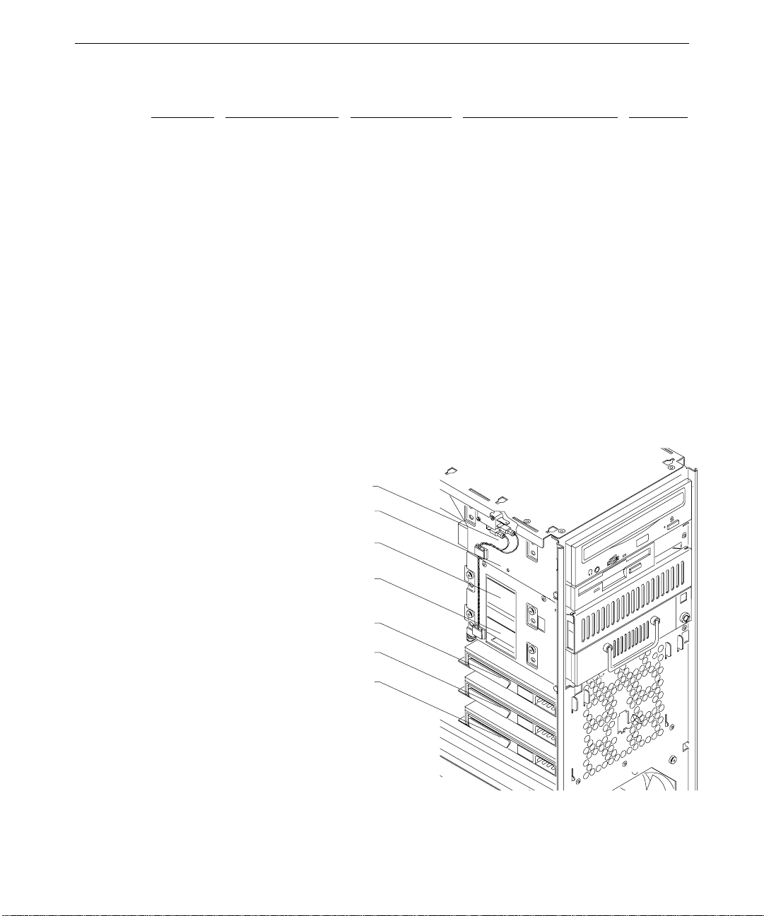
The following figure shows drive locations. Devices are installed in all locations for figure.
The EIDE CD-ROM, floppy drive, and system drive are standard. Other devices are
available as options.
NOTE If you are installing an additional EIDE device on the primary EIDE bus, you must mount the
device in Location 5 due to cabling restrictions.
EIDE CD-ROM (CDSK177)—Location 7
Floppy Drive (CDSK146)—Location 6
Add-on device—Location 5
Add-on device—Location 4
Add-on drive—Location 3
Add-on drive—Location 2
System drive—Location 1
Page 51
Installing Dev ices in the Drive Bays
NOTE Two internal bay drive brackets are installed in the chassis for mounting drive mechanisms.
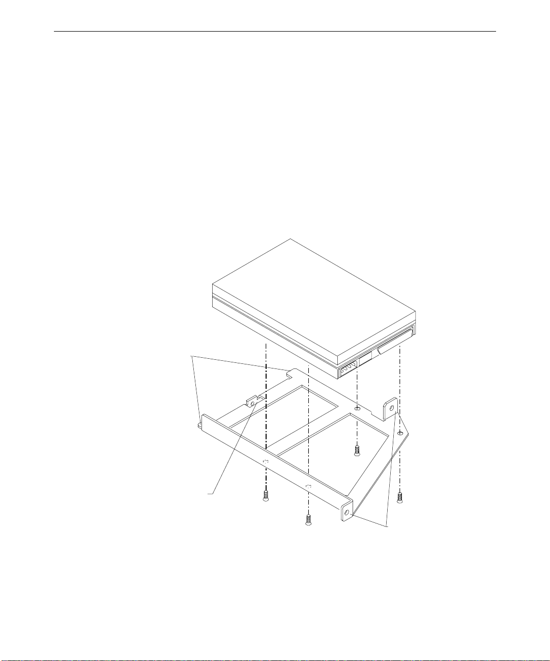
To install a drive in the external drive bay:
1. Remove the two screws that secure the external bay disk drive tray to the chassis. See
the following figure.
43
External bay mounting screws
2. From inside the chassis, push the tray out of the external bay. Then grasp the front of
the tray and slide it out of the bay.
3. Do all of the following:
−
Set the SCSI ID on the new drive to an unused ID number
−
Disable termination on the new drive
See Chapter 6, “Peripherals,” for details on these tasks.
4. Do one of the following:
−
If installing a standard disk drive, place the disk drive in the tray, align the
mounting holes, and install the four mounting screws
−
If installing a 1.6-inch device, such as a tape drive or a CD writer, remove the
mounting guide from the drive tray and attach the guide to the right side of the
device
−
If installing a Kingston removable disk drive module, do not use the mounting
guide
Page 52
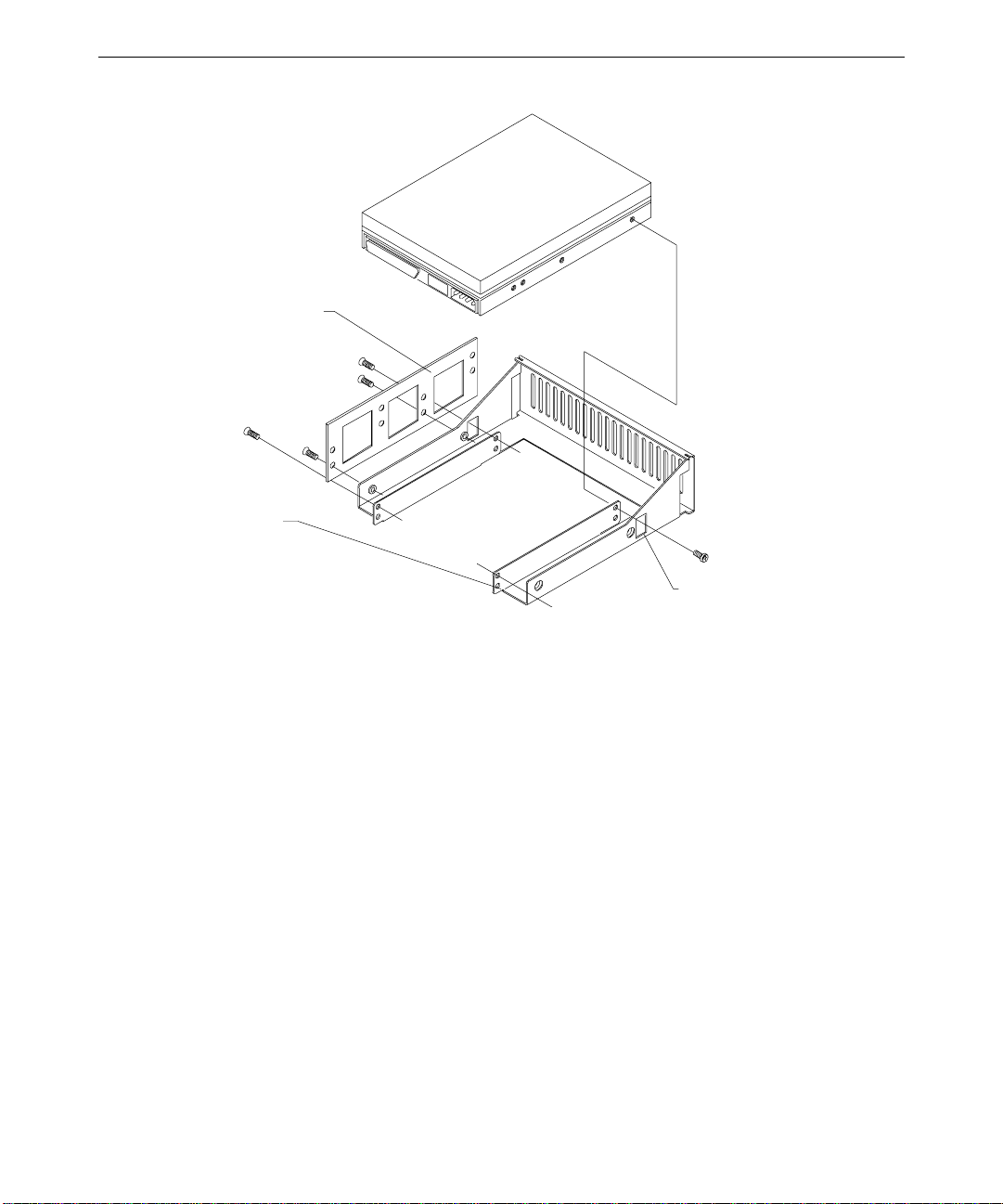
44
y
Mounting guide
Drive tra
Access hole (2)
5. Do one of the following:
−
Slide the tray assembly into the chassis, align the mounting holes, and install the
screws
−
Slide the 1.6-inch device into the chassis, align the mounting holes, and install the
screws provided in the package found in the Accessory Box
−
Slide the removable disk drive module into the chassis, align the mounting holes,
and install the mounting screws on the left and right sides of the chassis
6. Connect the SCSI cable and the power cable to the disk drive.
To install a drive in the internal bay:
1. Remove the right and left covers. See Chapter 1, “Accessing the System,” for details.
2. Remove the two screws that secure the spare drive bracket assembly to the left side of
the chassis.
3. Grasp the drive bracket assembly and remove the screw that secures the bracket to the
right side of the chassis.
4. Pull the drive bracket assembly out of the chassis.
Page 53

5. Do all of the following:
−
Set the SCSI ID on the new drive to an unused ID number
−
Disable termination on the new drive
See Chapter 6, “Peripherals,” for details on these tasks.
6. Install the bracket on the new drive.
Alignment tabs
45
Rear mounting tab
Front mounting tabs
7. Insert the alignment tabs into the appropriate slots in the chassis.
Page 54
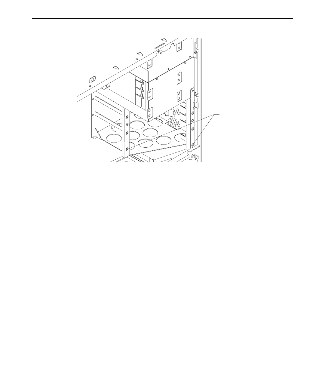
46
Screw holes for front mounting tabs
8. Install the two screws that secure the drive bracket assembly front mounting tabs to the
chassis.
9. Install the screw that secures the drive bracket assembly to the right side of the chassis.
10. Install the right cover.
11. Connect the SCSI cable and the power cable to the new drive.
Adding External SCSI Drives
You can add single-ended external SCSI drives to the system by connecting them to a SCSI
port on the back of the system. The TDZ 2000 features a standard Ultra SCSI external port.
A Wide Ultra SCSI external port is optional. See “External Ports” in Chapter 5, “System
Board,” for a figure of port locations.
You can also install additional SCSI expansion cards (adapters) to support external SCSI
drives. See the “Adding Expansion Cards” above for details.
NOTE Most SCSI adapters do not recognize a hard disk drive that was formatted using a different
brand of adapter. For example, a hard disk drive formatted with an Adaptec SCSI adapter
will not work with a Symbios SCSI adapter. You must use only Symbios-formatted hard disk
drives with a Symbios SCSI adapter.
Page 55

SCSI Cable Length Guidelines
The number of drives and length of the cables used to connect the drives is a factor when
using SCSI-1, Fast SCSI (SCSI-2), Ultra SCSI, and Wide Ultra SCSI drives. Fast SCSI,
Ultra SCSI, and Wide Ultra SCSI impose shorter cable restrictions than SCSI-1. The total
length of the SCSI cabling must not exceed the following:
47
Drives
1 to 4 19.8 ft
5 to 7 9.9 ft
NOTE The SCSI controller (on the system board or an adapter card) counts as one device.
SCSI-1 Fast SCSI-2 Ultra SCSI Wide Ultra SCSI
(6 meters)
(3 meters)
9.9 ft
(3 meters)
9.9 ft
(3 meters)
9.9 ft
(3 meters)
4.5 ft
(1.5 meters)
9.9 ft
(3 meters)
4.5 ft
(1.5 meters)
The total length of the SCSI cabling is the sum of the following:
u
Wide Ultra SCSI cable inside the system—52 inches (132 cm)
u
Ultra SCSI cable inside the system—14 inches (35.5 cm)
u
SCSI cable inside each device—average 8 inches (20 cm)
u
SCSI cable between the system and the first device
u
SCSI cable between each device
SCSI Cable Quality Guidelines
To ensure data integrity and optimum performance, do the following:
u
Use only Intergraph SCSI cables. Cables from other vendors may not provide adequate
shielding.
u
Use the shortest cables possible to connect SCSI devices to the system and to each other.
SCSI ID Guidelines
By default, specific devices use the following SCSI IDs:
u
System disk drive (standard) uses ID 0
u
SCSI bus always uses ID 7
u
Read/write CD-ROM (optional) drive uses ID 4
u
4 mm DAT drive (optional) uses ID 6
u
Iomega Jaz drive (optional) uses ID 6
Page 56

48
NOTE To easily determine the ID of each SCSI device on the system, restart the system. When the
BIOS screen displays, look for the list of SCSI devices and write down the ID for each device.
Some SCSI devices feature push switches to set the ID, while others have DIP switches or
jumpers. See the vendor documentation for details on setting the ID.
SCSI Termination Guidelines for External Devices
Follow the guidelines below for terminating SCSI devices:
u
Enable termination on the last external drive on the SCSI cable chain.
u
Disable termination on all other external drives on the SCSI cable chain.
u
Use only an active terminator on externally-terminated devices.
Connecting the Device
To add an external SCSI device:
1. Connect one end of the external SCSI cable to one of the following external ports:
−
The standard Ultra SCSI port, located just under the AC line out connector
−
The optional Wide Ultra SCSI port, located on the right side of the I/O panel
2. Connect the other end of the cable to the SCSI device.
3. Set the SCSI ID of the device to an unused number.
4. If the SCSI device is:
−
the last or only device on the SCSI chain, enable SCSI termination
−
NOT the last or only device on the SCSI chain, disable SCSI termination
5. Ensure that the power switch on the device is in the off position, and then connect the
power cord to the device and then to an AC receptacle.
6. Turn on the power to the device and any other devices on the SCSI chain.
7. Start the system. If necessary, install the software drivers and configure the drive
according to the vendor’s instructions.
Changing SCSI Host A d apter or Device Settings
Depending on your system configuration or the capabilities of SCSI devices connected to
your system, you may need to use the SCSI Configuration Utility to change host adapter or
device settings. See Chapter 3, “Configuring the System,” in the TDZ 2000 System Setup for
details.
Page 57

4 System Hardware Overview and
Specifications
This chapter contains general, technical information about the hardware in a TDZ 2000.
System Configuration Summary...................................................................................50
System Board...............................................................................................................51
Hardware Monitoring and Power Management ............................................................51
Intrusion Alert Switch....................................................................................52
Temperature Sensors...................................................................................... 53
System Model Number.................................................................................................53
Specifications...............................................................................................................54
Optional Hardware.......................................................................................................54
49
Page 58

50
System Configuration Summary
The following table summarizes the main features of the system.
Feature
Processors One or two 300 MHz Intel Pentium II with external 512 KB cache
Memory Four banks, one DIMM per bank, non-interleaved
Memory Width 72 bits, ECC protected
Memory Style Industry-standard 168-pin, unbuffered DIMM
Memory Type SDRAM (Synchronous Dynamic Random Access Memory)
Memory Speed 66 MHz
Memory Density Single or double density
Minimum/Maximum
memory
Memory Expansion 64 or 128 MB increments
Networking 10/100BaseT/TX Ethernet
SCSI One dual channel, 16-bit, Fast-20 Wide SCSI-3 controller for
EIDE Primary EIDE port for CD-ROM (standard)
Mouse Primax
Keyboard PS/2 style, NMB multimedia with speakers
Graphics Intergraph RealiZm II (ZX13, ZX25, & VX25 )
System Disk Drive 4.3 GB or 9.1 GB 10,000 RPM (Wide Ultra, SMART)
CD-ROM 24X EIDE CD-ROM (standard) or 4X/2X SCSI CD Writer
I/O Slots Six full-length PCI, one full-length PCI/ISA, one full-length
Peripheral Bays Three 3.5-inch x 1-inch or two 3.5-inch x 1.6-inch internal bays for
I/O Ports One PS/2 Mouse Port and one PS/2 Keyboard Port
Description
64 MB (1-8Mx72 minimum); 512 MB (4-16Mx72 maximum)
internal and external SCSI devices
Accelerated Graphics Port (AGP)
system disk and optional disks
One 3.5-inch x 1.0-inch external bay for floppy drive
One 5.25-inch x 1.6-inch external bay for CD-ROM
Two 5.25-inch x 1.6-inch external bays for optional devices
One Parallel Port, EPP- and ECP-compatible
Two Serial (COM) Ports
MIDI/Game Port
Two Universal Serial Bus (USB) Ports
Page 59

Feature Description
Power Supply 500 Watts, auto-ranging
System Board
The following table lists the main chip components on the MSMT401 system board.
51
One Fast-SCSI 3 (Ultra) Port (standard)
One Fast Wide SCSI 3 (Wide Ultra) Port (optional)
Ethernet Port (RJ45 connector)
Audio Ports: Microphone, Line In, Line Out
Component
System BIOS
Processor(s) Intel Pentium II; 300 MHz, SEC (Single Edge Connector)
Host-to-PCI Bridge Intel 82443LX
Sound Controller Crystal CS4237B
Ethernet Controller Intel 82558 10/100BaseTX PCI
SCSI Controller Symbios SYM53C876
Combo Controller Standard Microsystems FDC37C682
PCI-to-ISA Bridge Intel PIIX4
EIDE Controller Intel 82371AB PCI/IDE Xccelerator
Universal Serial Bus Ports Intel 82371AB PCI/IDE Xccelerator
Description
American Megatrends BIOS 841xx
Hardware Monitoring and Power Management
The TDZ 2000 features advanced hardware monitoring and power management capabilities.
These capabilities help you save energy, prolong system life, and provide for future
functionality, such as remote system wakeup.
Page 60

52
The InterSite Hardware Monitor software reports the following key voltages and system
states:
u
All major voltages, including processor bus voltage; +5 V; +3.3 V; +12 V; -12 V
u
Processor voltage ID
u
Temperature at two locations (near primary processor and near expansion slots)
u
Fan speed
u
Low battery voltage alert
u
Chassis intrusion security alert
See Chapter 2 in the System Setup for details on InterSite Hardware Monitor.
The top LED on the front panel indicates the following power states of the system:
LED
Power State Description Explanation
Green Working On System is fully usable; power conservation is on a per-
Off Mechanical
Off
If the power cord is plugged in, but the LED is off, then the system has a power voltage
problem. Call the Customer Response Center for assistance.
Refer to the System Setup for information about using the Automatic Shutdown Utility.
Intrusion Alert Switch
The intrusion alert switch (CSWX30800) is mounted at the top left side of the system near
the front. This microswitch is the only replaceable component in the hardware monitoring
system. If you detach the side panel when the system is off, the event is registered in the
InterSite Hardware Monitor software. See Chapter 2, “Servicing the System,” for details on
replacing the switch. See also InterSite Hardware Monitor Help for details.
device basis.
Off No power consumption. The system is
electromechanically off, disconnected from AC line
power, or is indicating that one of the supply voltages
is not correct. The system requires reconnection of
power or correction of voltage problem and returns to
the Working state only after a full shutdown and
restart.
Page 61

Temperature Sensors
Resistive temperature sensors are located on the system board at U1 and U143, near the
primary processor and the expansion slots, respectively. These devices provide signals for
reporting temperature readout data to the InterSite Hardware Monitor software. The sensor
at U143 provides the signal for controlling fan speed. The temperature sensors are part of
the system board and are not field replaceable. See the system board diagram in Chapter 5,
“System Board,” for sensor location.
System Model Number
The model number on the unit identifies the system hardware and software configuration.
The following table defines the individual digits.
53
Digit
1: Series K: TDZ 2000
2: Processor Type 2: Single Intel Pentium II, 300 MHz, 512 KB cache
3. Graphics 0: No graphics
4: Chassis 0: Workstation
5: Memory 0: No memory
6: CD-ROM 0: No CD-ROM
7: Disk Drives R: 4.3 GB 10,000 RPM
8: Operating System 2: Windows NT Workstation
9: Revision Variable
Meaning
3: Dual Intel Pentium II, 300 MHz, 512 KB cache
7: G97 Matrox Millennium II
8: RealiZm II ZX13
A: RealiZm II ZX25
B: RealiZm II VX25
V: With Kingston Removable Drive Module
6: 64 MB
7: 128 MB
3: EIDE CD-ROM
5 SCSI CD-ROM
S: 9.1 GB 10,000 RPM
Page 62

54
Specifications
The following specifications apply to the TDZ 2000.
Item
Dimensions
Weight 55 LB. (25 kg) fully configured
Maintenance
clearance
AC line voltage (US) 90 - 132 VAC, 47 - 63 Hz, 1 phase, 15A/125 V receptacle
AC line voltage
(International)
Power consumption 780 W (based on 6.5 A, 120 VAC, 60 Hz)
Recommended room
temperature
Recommended room
humidity
Heat dissipation 2,662.14 BTU/hr
Optional Hardware
If your system includes any of the following hardware, see the documentation delivered with
that hardware for additional information:
u
Display (single, double, triple)
Specifications
25.8 x 7.9 x 20.2 inches (65.4 x 20.0 x 50.8 cm)
36 inches (91.4 cm) front and back
180 - 264 VAC, 47 - 63 Hz, 1 phase, 15A/250 V receptacle
50° to 80° F (10° to 26° C)
20% to 80% (non-condensing)
u
External SCSI CD-ROM, SCSI CD-ROM reader/writer, SCSI optical drive, or SCSI
disk drive
u
Removable SCSI disk drive
Page 63

5System Board
This chapter provides cable and jumper connector information, major component
descriptions, memory subsystem details and addresses, and external port pinouts for the
MSMT401 (Revision A) system board.
Slots and Sockets.........................................................................................................56
Cable Routing and Pinouts...........................................................................................57
Jumper Connectors ......................................................................................................62
External Ports ..............................................................................................................64
Sound Controller .........................................................................................................72
Configuration Data ......................................................................................................73
DMA Channels ..............................................................................................73
Input/Output Addresses..................................................................................73
Memory Address Map....................................................................................73
PCI to ISA Bus Interrupt Mapping .................................................................74
Interrupt Requests (IRQs)...............................................................................75
55
Page 64

56
Board Identification Numbers
Slots and Sockets
The following diagram shows the location of slots and sockets on the system board.
Temp Sensor - U1
Primary Processor Slot - J3
Secondary Processor Slot - J8
Bank 0 - J19
Bank 1 - J25
Bank 2 - J26
Bank 3 - J30
Slot 0 - AGP
Slot 1 - PCI
Slot 2 - PCI
Slot 3 - PCI
Slot 4 - PCI
Slot 5 - PCI
Slot 6 - PCI
Memory Sockets (SDRAM
DIMM Slots)
Expansion
Slots
Slot 7 - PCI
Slot 7 - ISA
Page 65
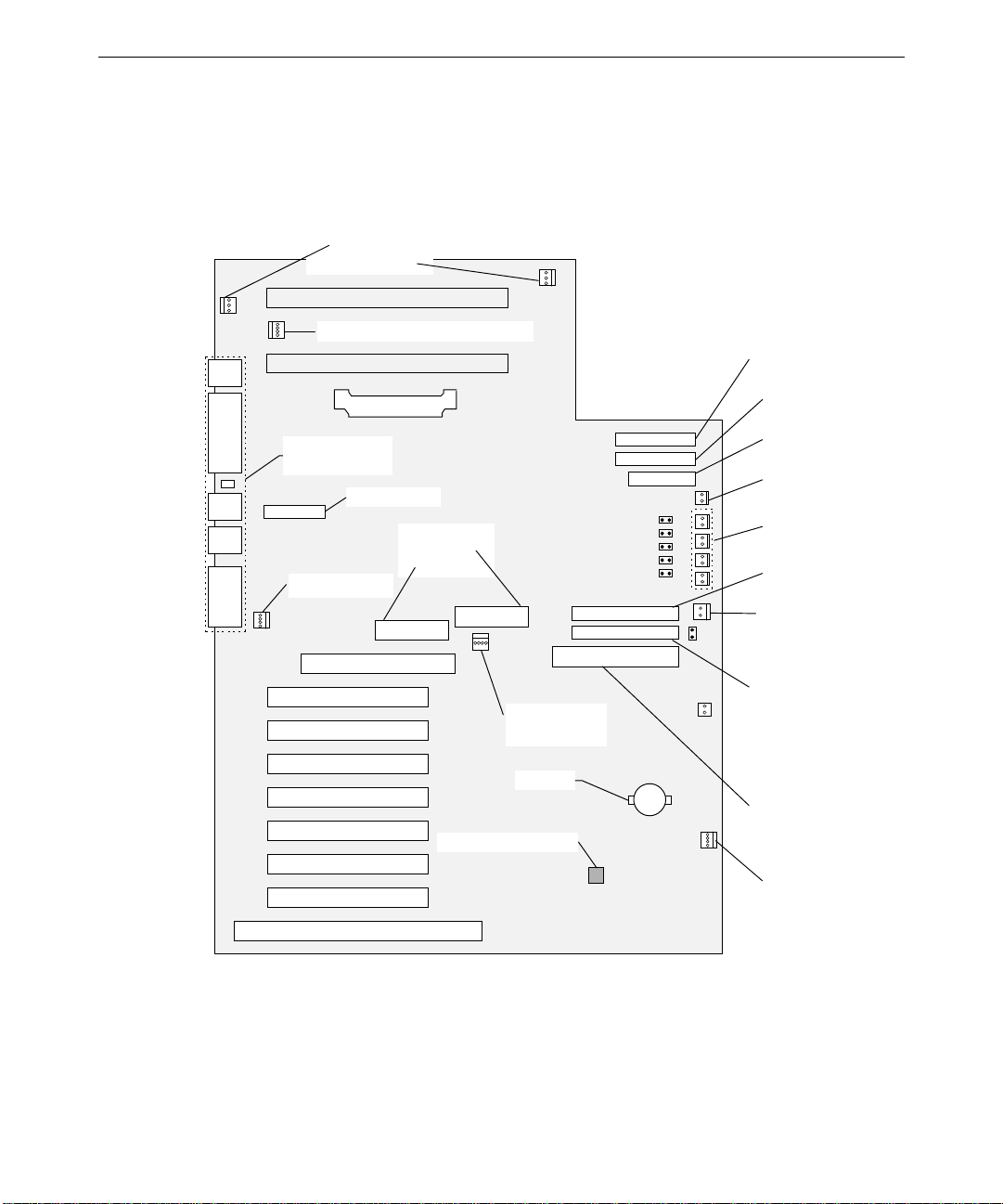
Cable Routing and Pinouts
The following figure shows the cable connectors and other components on the system board.
CPU Fan (optional)
Primary - J4
Secondary - J1
Chassis Fan 1 - J5
57
Second ary IDE - J15
VRM - J10
External
Port Connectors
Seria l 2 - T1
CD Audio - J37
Power Supply
P1 - J34
P2 - J38
Temp Sensor - U143
Power Supply
Fan - J39
Battery
Primary IDE - J16
Floppy Drive - J18
Power Switch - J22
LED Connectors
Extern al Wide Ultra
SCSI - J35
Chassis Intr usion - J36
Interna l Wide Ultra
SCSI-J40
External Ultra
SCSI - J44
Chassis Fan 2 - J54
Page 66

58
The following tables lists jumper, connector, cable, and device connection details.
NOTE See Chapter 7, “Power Supply, Fans, and Hardware Monitoring Devices,” for power
connectors J34 and J38. See also Chapter 6, “Peripherals,” for details on data cables.
From Board Connector Cable To
J4 Boxed processor fan
— Optional CPU fan
(primary)
J1 Boxed processor fan
— Optional CPU fan
(secondary)
J37 CD-ROM Audio MCBL122A EIDE CD-ROM CDSK177
J5 Chassis Fan 1 CFAN12009 Fan, top rear
J54 Chassis Fan 2 CFAN12009 Fan, bottom front
J33 Disk Activity LED MCBL247A Front panel disk activity LED (green)
J18 Floppy MCBL067A Floppy drive CDSK146
J36 Intrusion Alarm MCBL251A Intrusion alarm switch CSWX30800
J29 LED Power MCBL248A Front panel power LED (green)
J23 LED Power MCBL249A Front panel power LED (yellow)
J22 Main Power MCBL250A Front panel power button
J39 Power supply fan P10 Fan, power supply, 2- or 4-wire
J16 Primary EIDE MCBL252A EIDE CD-ROM CDSK177
J44 SCSI, External Ultra MCBL253A3 MSMT283 terminator/adapter with 50-
pin high-density external connector
J35 SCSI, External Wide
MCBL255A Rear panel 68-pin connector, optional
Ultra
J40 SCSI, Internal Wide
MCBL254A System disk at SCSI ID 0
Ultra
T1 Serial Port 2 MCBLW680A Rear panel external serial port 2
(COM2)
J1, J4 - Boxed Processor Fan (optional)
Pin
Signal Pin Signal
1 Ground 3 Tach
2 +12V
Page 67

J37 - CD-ROM Audio, MCBL122A, EIDE CD-ROM CDSK177
Signal Pin Signal
Pin
1 Right Sound Channel 3 Left Sound Channel
2 Ground 4 Ground
J5 - Chassis Fan 1, CFAN12009 (top rear)
Signal Color Pin Signal Color
Pin
1 Fan control input Brown 3 Voltage + Red
2 Fan Tach White 4 Return - Black
J54 - Chassis Fan 2, CFAN12009 (bottom front)
Same as J5.
J33 - Disk Activity LED (green), MCBL247A
59
Pin
Signal Color
1 DiskActive Orange
2 Ground Black
J18 - Floppy Disk Drive, MCBL067A, CDSK146
Pin
Signal Pin Signal Pin Signal
2 RPM 14 DRV0- 26 TRK04 No connect 16 MTR1- 28 WRPRT6 DRATE0 18 DIR 30 RDATA8 INDEX- 20 STEP- 32 HDSEL
10 MTR0- 22 WDATA- 34 DSKCHG
12 DRV1- 24 WGATE-
J36 - Intrusion Alarm, MCBL251A, Switch CSWX30800
Signal Color
Pin
1 Alarm Red
2 Ground Black
Page 68

60
J29 - Power On LED (green), MCBL248A
Signal Color
Pin
1 PwrGood White
2 Ground Black
J23 - Power Managed LED (yellow), MCBL249A
Signal Color
Pin
1 PwrGood Blue
2 Ground Black
J22 - Main Power, MCBL250A, Front Panel Standby Switch
Signal Color
Pin
1 + 5 V trickle White
2 PWRBTN Green
J39 - Power Supply Fan, P10, Power Supply, 2-Wire
Signal Color
Pin
1 Voltage + Red
2 Return - Black
J39 - Power Supply Fan, P10, Power Supply, 4-Wire
Signal Color Pin Signal Color
Pin
1 Fan control input Brown 3 Voltage + Red
2 Fan Tach 1 White 4 Return - Black
J16 - Primary EIDE, MCBL252A, EIDE CD-ROM CDSK177
Pin
Signal Pin Signal Pin Signal
1 BRSTDRV- 15 D01+(1) 28 VCC
2 Ground 16 D01+(14) 29 DOAK03 D01+(7) 17 D01+(0) 30 Ground
4 D01+(8) 18 D01+(15) 31 IRQ14
5 D01+(6) 19 Ground 32 IOCS166 D01+(9) 20 — 33 DA1
Page 69

Pin Signal Pin Signal Pin Signal
7 D01+(5) 21 D0RQ0- 34 —
8 D01+(10) 22 Ground 35 DA0
9 D01+(4) 23 DOIOW- 36 DA2
10 D01+(11) 24 Ground 37 CS1P11 D01+(3) 25 D0IOR- 38 CS3P12 D01+(12) 26 Ground 39 IDEACTVP13 D01+(2) 27 IORDY 40 Ground
14 D01+(13)
J35 - SCSI, External Wide Ultra, MCBL255A, 68-Pin Connector (optional)
61
Pin
Signal Pin Signal Pin Signal
17 TERMPWR 45 SD-(5) 57 SBSY18 TERMPWR 46 SD-(6) 58 SACK35 SD-(12) 47 SD-(7) 59 SRSI36 SD-(13) 48 SDP0- 60 SMSG37 SD-(14) 49 Ground 61 SSEL38 SD-(15) 50 Ground 62 SCD39 SDP1- 51 TERMPWR 63 SREQ40 SD-(0) 52 TERMPWR 64 SIO41 SD-(1) 53 No connection 65 SD-(8)
42 SD-(2) 54 Ground 66 SD-(9)
43 SD-(3) 55 SATII- 67 SD-(10)
44 SD-(4) 56 Ground 68 SD-(11)
Remaining pins connected to ground.
J40 - SCSI, Internal Wide Ultra, MCBL254A, System Disk/Other SCSI Devices
See “J35” above.
Page 70

62
J44 - SCSI, External Ultra, MCBL253A, MSMT383 Terminator
Signal Pin Signal Pin Signal Pin Signal
Pin
2 SD-(0) 16 SD-(7) 30 Ground 44 SSEL4 SD-(1) 18 SDP0- 32 SATII- 46 SCD6 SD-(2) 20 Ground 34 Ground 48 SREQ8 SD-(3) 22 Ground 36 SBSY- 50 SIO10 SD-(4) 24 Reserved 38 SACK12 SD-(5) 26 TPWR 40 SRST14 SD-(6) 28 Reserved 42 SMSG-
Remaining pins connected to ground.
T1 - Serial Port 2, MCBLW680A, External Serial Port 2
See pinouts for “Serial” below.
Jumper Connectors
The following table shows the jumper settings for CPU frequency. IN denotes the jumper is
installed on both pins. The jumpers are located to the right of the DIMM slots. See the
system board diagram above for details.
NOTE BIOS version 8410F or higher must be installed to use a 333 MHz Pentium II processor.
Earlier BIOS versions do not support frequencies higher than 300 MHz.
Jumper 266 MHz 300 MHz 333 MHz
J21 ON ON OFF
J27 OFF OFF OFF
J28 ON OFF ON
J31 ON ON ON
The following figure shows the jumper locations on the system board.
Page 71
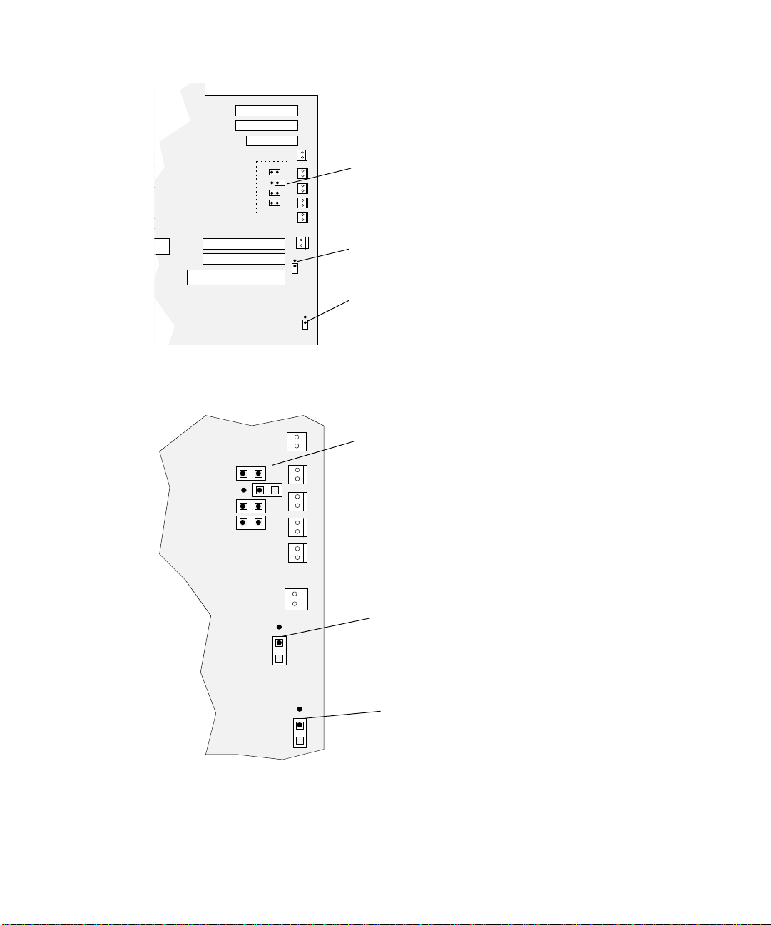
CPU Frequency
SCSI Term
Password
Clear
The following figure details the jumper settings.
63
J21 - ON
J27 - OFF
J28 - OFF
J31 - ON
OFF
OFF
CPU Frequency.
Settings for 266 MHz
(Default)
SCSI Term - J4 1
Password
Clear - J47
Do not change CPU
Frequency jumper
settings.
OFF (default) means
termination is enabled.
Add a jumper to disable
termination.
OFF means BIOS checks
for password during boot .
ON means BIOS will not
check for password.
Page 72
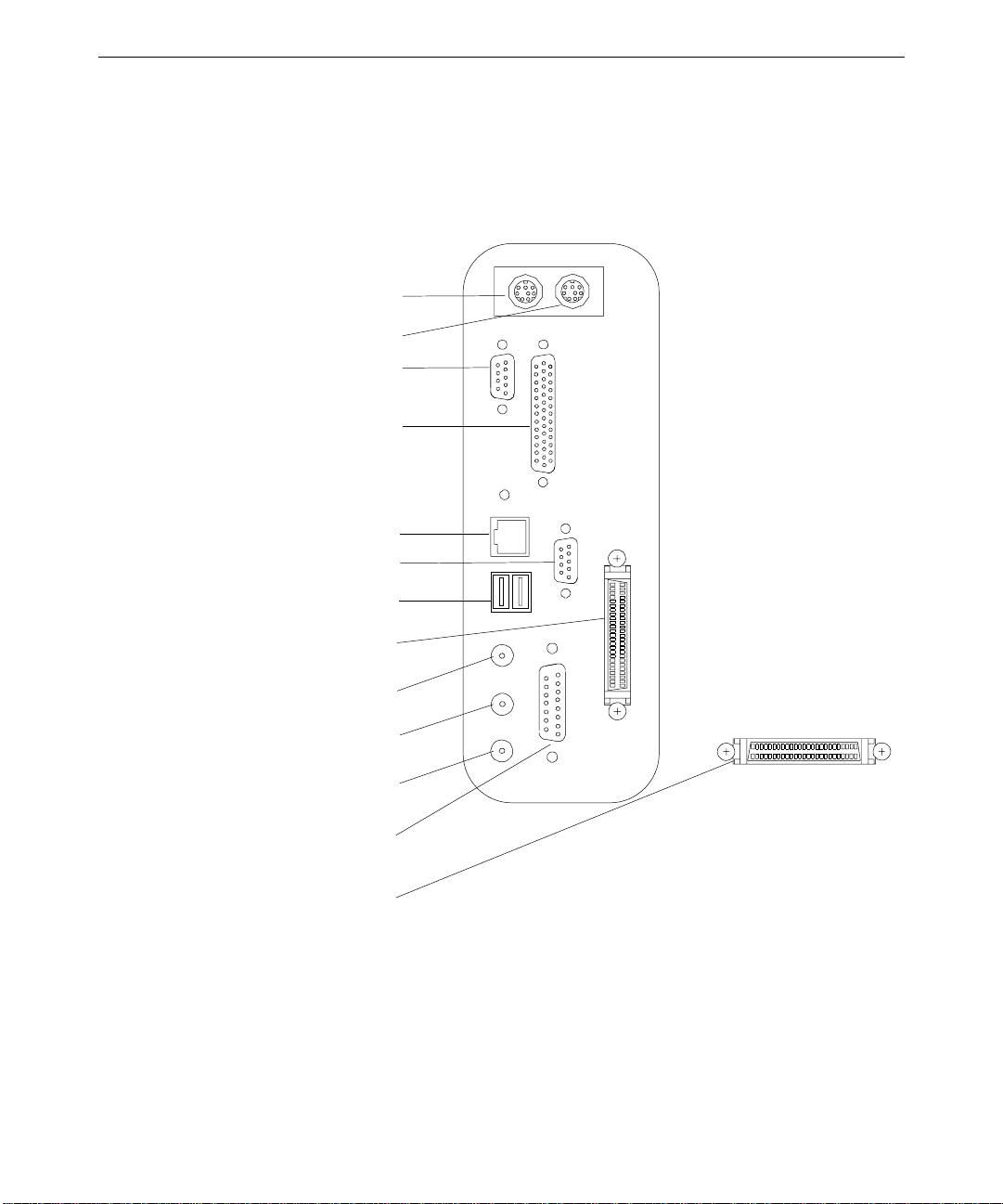
64
)
)
External Ports
The following figure shows the external ports on the back of the unit.
COM 1 (Serial
COM 2 (Serial
Keyboard
Mouse
Parallel
Ethernet
Universal Serial Bus
External Wide Ultr a
SCSI (optional)
Microphone
Audio Line I n
Audio Line O ut
MIDI/Game
External Ultra
SCSI (standard)
Page 73
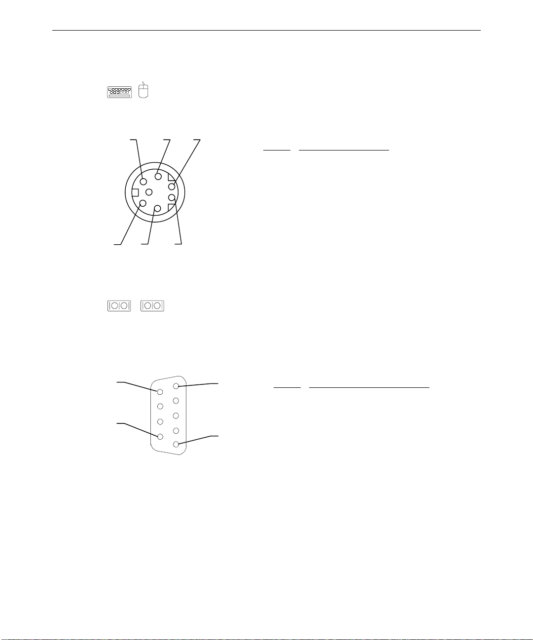
Keyboard, Mouse
The keyboard and mouse ports are PS/2 style, 6-pin ports. They are not
interchangeable.
65
2 4 6
Pin
Signal
1 KDATA (keyboard)
MDATA (mouse)
2 Spare
3 Ground
4 VCC
5 KCLK
1 3 5
6 Spare
Serial
1
2
The serial ports (also referred to as RS-232 asynchronous communications
ports, or COM ports) connect modems, printers, peripherals, and other computers to the
system. The serial ports (labeled 1 and 2) are 9-pin, male DB9 connectors. If connecting a
serial device with a 25-pin DB25 connector, use a 25-pin to 9-pin adapter cable to mate with
the serial port on the system. Use only shielded cables with the serial ports.
6
1
Pin
Signal
1 DCD - Data Carrier Detect
2 RD - Receive Data
9
5
3 TD - Transmit Data
4 DTR - Data Terminal Ready
5 Ground
6 DSR - Data Set Ready
7 RTS - Request to Send
8 CTS - Clear to Send
9 RI - Ring Indicator
Page 74

66
Parallel
The parallel port is used almost exclusively for printers, but is compatible with any
peripheral device designed to interface with a standard Centronics-type parallel port. Use
only shielded cables with the parallel port (DB-25).
14
1
Pin
Signal Pin Signal
1 -Strobe 10 -ACK - Acknowledge
2 Data 0 11 Busy
3 Data 1 12 PE - Paper Empty
4 Data 2 13 +Select
5 Data 3 14 -Auto FDXT - Auto
Feed
6 Data 4 15 -Error
7 Data 5 16 -Init - Start
8 Data 6 17 -SLCTIN - Select
25
13
9 Data 7 18-25 Ground
Audio Line Out
The Audio Line Out port connects the speaker jack of the NMB multimedia keyboard to
the computer. You can also use the port to connect other audio output devices, such as stereo
speakers or headphones, a tape deck or an external amplifier, to the computer.
2
5
Pin
Signal
1 Ground
2 Left Channel Out
5 Right Channel
Out
1
Page 75

Audio Line In
The Audio Line In port connects audio input devices, such as a tape deck or a CD
player, to the computer.
67
2
5
Pin
Signal
1 Ground
2 Left Channel In
5 Right Channel In
1
Microphone
The Microphone port connects the microphone jack of the NMB multimedia keyboard
to the computer. You can also use the port to connect a headset microphone to the computer.
2
5
Pin
Signal
1 Ground
2 MIC 2
5 MIC 1
1
Page 76

68
Game/MIDI
The Game/MIDI port connects a game joystick or a MIDI device, such as a musical
keyboard or synthesizer, to the system.
Signal Pin Signal
15
1
Pin
1 +5V 9 +5V
2 Fire button 0 10 Fire button 2
3 X-axis,
11 X-axis, joystick 2
joystick 1
4 Ground 12 MIDI out
5 Ground 13 Y-axis, joystick 2
9
8
6 Y-axis,
joystick 1
14 Fire button 3
7 Fire button 1 15 MIDI in
8 +5V
Ethernet
The Ethernet port connects a network cable (with an RJ45 connector) to the computer.
1
Pin
Signal Pin Signal
1 TD+ - Transmit 5 Reserved
2 TD– - Transmit 6 RD– - Receive
3 RD+ - Receive 7 Reserved
8
4 Reserved 8 Reserved
Page 77

69
Universal Serial Bus
The Universal Serial Bus (USB) port connects USB devices to the computer. These
devices can include printers, keyboards and other peripherals that have historically used
serial, parallel, mouse, and keyboard I/O buses. USB devices, designed to be fully Plug-andPlay (PnP), feature hot attach/detach and daisy-chain capabilities. The USB port can
transfer data at a maximum theoretical rate of 12 megabits per second.
1 4
Signal Pin Signal
Pin
A1 PWR B1 PWR
A2 - B2 -
B
A3 + B3 +
A4 GROUND B4 GROUND
A
1 4
Page 78

70
External Ultra SCSI
The external Ultra SCSI port (standard) connects external SCSI devices, such as tape
drives or hard disks, to the computer. The maximum sustainable data transfer rate is 20 MB
per second.
50
26
25
1
Pin
26 Command Data-0
27 Command Data-1
28 Command Data-2
29 Command Data-3
30 Command Data-4
31 Command Data-5
32 Command Data-6
33 Command Data-7
34 Command Data Parity
38 Terminator Power
41 Attention
43 Busy
44 Acknowledge
45 Reset
46 Message
47 Select
48 Command
49 Request
50 Input/Output
Signal
NOTE Pins 12, 13, 14, 37, and 39 are not connected; pins not listed are connected to ground.
Page 79

External Wide Ultra SCSI
The external Wide Ultra SCSI port (optional) connects Wide Ultra SCSI devices, such
as tape drives or hard disks, to the computer. This port has a maximum theoretical
sustainable data transfer rate of 40 MB per second.
71
68
35
34
1
Pin
Signal Pin Signal
17 TERMPWR 50 Ground
18 TERMPWR 52 TERMPWR
35 SD-(12) 53 No connection
36 SD-(13) 54 Ground
37 SD-(14) 55 SATII38 SD-(15) 56 Ground
39 SDP1- 57 SBSY40 SD-(0) 58 SACK41 SD-(1) 59 SRSI42 SD-(2) 60 SMSG43 SD-(3) 61 SSEL44 SD-(4) 62 SCD45 SD-(5) 63 SREQ46 SD-(6) 64 SIO47 SD-(7) 65 SD-(8)
48 SDP0- 66 SD-(9)
49 Ground 67 SD-(10)
51 TERMPWR 68 SD-(11)
NOTE Pins not listed are connected to ground.
Page 80

72
Sound Controller
The sound controller is the Crystal CS4237B. Integrated onto the system board, the
controller is a complete, fully-featured PC 97 compliant sound implementation. It has the
following specifications:
Feature
Audio Resolution 16-bit
MIDI/UART Mode
Compatibility
Bus Interface 16-bit ISA
CODEC Delta Sigma-based Windows Sound System
CODEC FIFO 16 Samples
FM Synthesizer Crystal internal FM synthesis
External Audio Inputs Microphone (Monaural), Stereo Line-In
Internal Audio Inputs Stereo FM Synthesis, Stereo Wave Data, Stereo CD,
Audio Outputs Stereo Line-Out
MIDI/Joystick MIDI In, MIDI Out, up to 4 fire buttons
ADPCM Audio
Compression
Sampling Rate Range 5 KHz - 44.1 KHz in 228 selectable steps
The Crystal CS4237B sound controller is configured entirely through I/O port accesses.
When the system is powered up, the hardware forces the Crystal CS4237B to respond to
default I/O port addresses, interrupt request (IRQ) level, and direct memory access (DMA)
request and acknowledge. The following table shows the default sound controller
configurations and available programmable settings.
Specification
Roland MPU401
Monaural PC Speaker
4:1, 3:1, and 2:1
Parameter
Base I/O Address / MPU-401 220/330
8-bit Playback DMA 1
8-bit Capture DMA 3
Base IRQ / MPU IRQ 5/15
Default
Page 81

Configuration Data
DMA Ch annels
The system board uses Direct Memory Address (DMA) channels to exchange data without
accessing the CPU. Some channels are assigned for specific use by the system, as defined
below. Each DMA channel appropriates full 32-bit processing. For an ISA bus, channels 0
through 3 are 8-bit and channels 4 through 7 are 16-bit channels.
73
DMA
0 LPT 4 Cascade input for 0-3
1 Crystal CS4237B Controller 5 Spare
2 Floppy Controller 6 Spare
3 Crystal CS4237B Controller 7 Spare
Assignment DMA Assignment
Input/Output Addresses
The following table lists a small subset of the reserved I/O addresses.
Address
0278 - 027F Parallel Port LPT2
02E8 - 02EF Serial Port COM4
02F8 - 02FF Serial Port COM2
0378 - 037F Parallel Port LPT1
03B0 - 03BF Monochrome Display/Printer Adapter
03C0 - 03CF Enhanced Graphics Adapter (EGA/VGA)
03D0 - 03DF Color/Graphics Monitor Adapter (CGA/MCGA)
03F0 - 03F7 Floppy Controller
03F8 - 03FF Serial Port COM1
Device
Memory Address Map
The following table lists the memory address map assignments.
Memory Address
00000000 - 0009FFFF 640K System board memory
000A0000 - 000BFFFF 128K Video memory
000C0000 - 000C7FFF 32K Video ROM
Size Assignment
Page 82

74
Memory Address Size Assignment
00000000 - 0009FFFF 640K System board memory
000C8000 - 000DFFFF 96K Available I/O Adapter ROM
000E0000 - 000EFFFF 64K BIOS ROM and PCMCIA
000F0000 - 000FFFFF 64K BIOS ROM
00100000 - 1FFFFFFF 511M Expansion memory
20000000 - 3FFFFFFF — Reserved
PCI to ISA Bus In terrupt Mapping
The ISA bridge provides the sixteen conventional ISA interrupts, plus four interrupt request
pins for PCI peripheral interrupts (PIRQ0 through PIRQ3). For PC-AT architecture
compatibility reasons, the PCI interrupts are routed to the ISA interrupts within the ISA
bridge. The assertion of a PCI interrupt concludes in an ISA interrupt being asserted.
Bit 7 of each PIRQ registers enable (Low) or disable (High) the routing of the PIRQ to an
ISA interrupt. The lowest four bits (3:0) of each PIRQ register determines to which ISA
interrupt the PIRQ is routed. You can map the PIRQs to the following ISA interrupts:
IRQ 5, 10, 11, 15
You can also map to IRQ 3, 4, 7, 12, and 14, but other devices are disabled if you do so.
Each PCI slot has four available interrupt lines: INTA, INTB, INTC, and INTD. These are
connected to the PCI interrupts, PIRQ0 through PIRQ3, as shown below:
Interrupt Line
INTA PIRQ0 PIRQ1 PIRQ2 PIRQ3 PIRQ0 PIRQ1 PIRQ2
INTB PIRQ1 PIRQ2 PIRQ3 PIRQ0 PIRQ1 PIRQ2 PIRQ3
INTC PIRQ2 PIRQ3 PIRQ0 PIRQ1 PIRQ2 PIRQ3 PIRQ0
INTD PIRQ3 PIRQ0 PIRQ1 PIRQ2 PIRQ3 PIRQ0 PIRQ1
Slot 1 Slot 2 Slot 3 Slot 4 Slot 5 Slot 6 Slot 7
Page 83

Interrupt Requests (IRQs)
System interrupt request (IRQ) assignments are defined below.
75
IRQ
0 System Timer 8 Real Time Clock
1 Keyboard 9 SMBUS/ACPI
2 Cascade input for IRQ8 - IRQ15 10 Crystal CS4237B Sound Controller
3 COM2, COM4 11 Spare
4 COM1, COM3 12 Mouse
5 MIDI port 13 Floating Point Unit
6 Floppy Controller 14 EIDE CD-ROM
7 Parallel Port 15 Hardware Monitor
You can assign the spare interrupt listed above to an ISA device. When you add a PCI
device to the system, the system BIOS automatically assigns the interrupt. However, at least
one interrupt must be available for the PCI bus.
When you add an ISA board, you must reserve the interrupt using the AMIBIOS Setup
utility and jumpers on the expansion board. See the TDZ 2000 System Setup for details on
using AMIBIOS Setup. See also the vendor documentation for the expansion board for
jumper and related information.
Name IRQ Name
Page 84

76
Page 85

6 Peripherals
This chapter provides information on the cabling and configuration of common peripherals
within the system.
Peripheral Cables.........................................................................................................78
Internal Wide Ultra SCSI Cable (MCBL254A) Connection Locations............78
Internal Ultra SCSI Cable (MCBL253A) Connection Locations .....................78
External Wide Ultra SCSI Cable (MCBL255A) Connection Locations...........79
EIDE Cable (MCBL252A) Connection Locations...........................................79
Floppy Cable (MCBL067A) Connection Locations.........................................80
Peripheral Configuration..............................................................................................80
EIDE CD-ROM Drive (CDSK177).................................................................80
SCSI CD Recorder (CDSK133)......................................................................81
Iomega Jaz 1 GB SCSI Internal Drive (CDSK168).........................................82
40 GB 8MM Tape Drive (CMTP169).............................................................83
Floppy Disk Drive (CDSK146).......................................................................84
4.3 GB and 9.1 GB Disk Drives (CDSK166, CDSK167) ................................ 84
77
Page 86

78
Peripheral Cables
This section provides information on peripheral cables and associated connections. See the
section, “Cable Routing and Pinouts,” in Chapter 5, “System Board,” for additional details.
Cable illustrations are not to scale. You can identify the cables and connectors using their
spacing as reference. Connectors for SCSI devices are spaced approximately 8 in (20 cm)
apart.
CAUTION You must disable termination on any SCSI device you install internally. If you do not disable
termination, the system may fail to start or may behave erratically.
Internal Wide Ultra SCSI Cable (MCBL254A) Connection
Locations
The following illustration and table show the cable connectors and the locations to which
they attach. This cable is approximately 52 in (132 cm) long.
1 765432
Connector Connects To
1 J40, system board
2 System Disk at Location 1 (internal bay)
3 Disk at Location 2 (internal bay)
4 Disk at Location 3 (internal bay)
5 Device at Location 4 (external bay)
6 Device at Location 5 (external bay)
7 Active terminator
See “Device Locations” in Chapter 3, “Upgrading the System,” for details on standard
peripheral locations.
Internal Ultra SCSI Cable (MCBL253A) Connection Locations
The following illustration and table show the cable connectors and the locations to which
they attach. This cable is approximately 36 in (91 cm) long.
Page 87
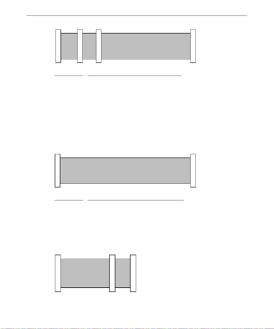
1 432
Connector Connects To
1 J44, system board
2 Device at Location 4 (external bay)
3 Device at Location 5 (external bay)
4 External SCSI Terminator board MSMT283
External Wide Ultra SCSI Cable (MCBL255A) Connection
Locations
The following illustration and table show the cable connectors and the locations to which
they attach. This optional cable is approximately 14 in (35.5 cm) long.
79
1 2
Connector Connects To
1 J35, system board
2 External SCSI 68-pin connector on rear panel
EIDE Cable (MCBL252A) Connection Locations
The following illustration and table show the cable connectors and the locations to which
they attach. This cable is approximately 10.5 in (26.7 cm) long.
1 32
Page 88
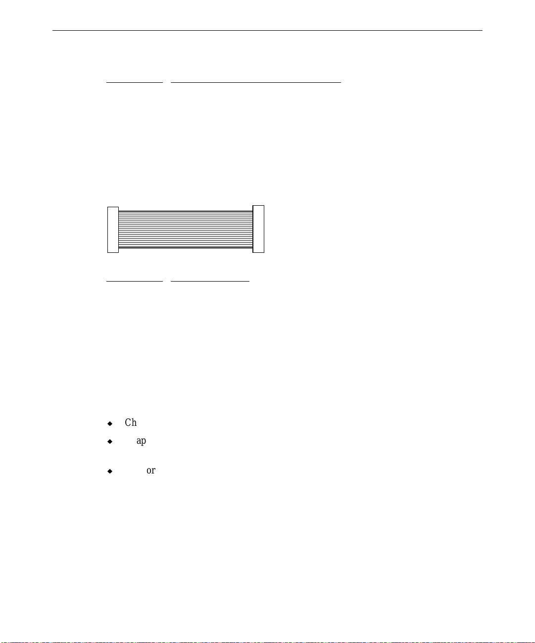
80
Connector Connects To
1 J16, system board
2 Device at Location 5 (external bay)
3 EIDE CD-ROM CDSK177 at Location 7
Floppy Cable (MCBL067A) Connection Locations
The following illustration and table show the cable connectors and the locations to which
they attach. This cable is standard and is approximately 17 in (43.1 cm) long.
1 2
Connector Connects To
1 J18, system board
2 Floppy disk drive
Peripheral Configuration
This section provides illustrations and information on configuring common peripherals for
the system.
See the following for related information:
u
Chapter 5, “System Board,” for cable connector locations and pinouts.
u
Chapter 7, “Power Supply, Fans, and Hardware Monitoring Devices,” for power cable
information and pinouts.
u
Vendor documentation provided with the peripheral device.
EIDE CD-ROM Drive (CDSK177)
The following figure shows the back of the EIDE CD-ROM drive.
Page 89

81
connect or
Audio connect or
Mode Select
(set to Maste r)
Device Connector Cable Connects to
Audio (analog) MCBL122A J37, system board
EIDE MCBL252A J16, primary EIDE, system board
Power P4 Power supply
The Mode Select header is jumpered “Master” as shown.
SCSI CD Recorder (CDSK133)
The following figure shows the back of the CD recorder.
EIDE c onnecto r
Power
Audio connector
ID1
ID2
ID4
Term Power jumper
Termination jumper
Parity Enable jumper
SCSI connector
Device Connector Cable Connects to
Audio (analog) MCBL122A J37, system board
Power P3; P5-P9 Power supply
SCSI MCBL254A J40, system board
Power
connector
Page 90

82
To disable SCSI termination, remove the Termination jumper and the Term Power jumper.
Use jumpers as defined in the following table to set the SCSI ID.
SCSI ID
ID1 ID2 ID4
0 OFF OFF OFF
1 ON OFF OFF
2 OFF ON OFF
3 ONONOFF
4 OFF OFF ON
5 ON OFF ON
6 OFF ON ON
Iomega Jaz 1 GB SCSI Internal Drive (CDSK168)
The following figure shows the jumpers on the bottom of the drive.
Front
Power conn ect o r
SCSI connector
ID4
ID2
ID1
Device Connector Cable Connects to
Power P3; P5-P9 Power supply
SCSI MCBL254A J40, system board
Page 91

83
The drive is not terminated and requires external termination only if installed as the last
device on the SCSI chain.
Use jumpers as defined in the following table to set the SCSI ID. The factory default address
is SCSI ID 5.
SCSI ID
ID1 ID2 ID4
0 OFF OFF OFF
1 ON OFF OFF
2 OFF ON OFF
3 ONONOFF
4 OFF OFF ON
5 ON OFF ON
6 OFF ON ON
40 GB 8MM Tape Drive (CMTP169)
The following figure shows the back of the tape drive.
SCSI connector
Device Connector Cable Connects to
Power P3; P5-P9 Power supply
SCSI MCBL254A J40, system board
Power connec tor
ID2 ID1
ID0
SCSI termination is permanently disabled.
Use jumpers as defined in the following table to set the SCSI ID.
SCSI ID
ID0 ID1 ID2
0 OFF OFF OFF
1 ON OFF OFF
2 OFF ON OFF
3 ONONOFF
Page 92

84
4 OFF OFF ON
5 ON OFF ON
6 OFF ON ON
Floppy Disk Drive (CDSK146)
The following figure shows the cable connectors on the back of the floppy disk drive.
Power
connector
Device Connector Cable Connects to
Power P3 Power supply
Data MCBL194A J18, system board
Data cable
connector
4.3 GB and 9.1 GB Disk Drives (CDSK166, CDSK167)
You can use either of the following Wide Ultra SCSI disk drives in the system:
Part Number
CDSK166 Seagate ST19101W 10,000 9.1 GB
CDSK167 Seagate ST34501W 10,000 4.3 GB
The following figure shows the jumper connectors J6 and J2 on the Seagate 4.3 GB and 9.1
GB disk drives. Remove the drive from its bracket to access J2.
Vendor Number RPM Capacity
Page 93

85
ID1
ID2
ID4
ID8
J6
J2
TE
oooooooo
oooooooo
TP
PD
SCSI
connector
Pin 1
Power
connector
Device Connector Cable Connects to
Power P3; P5-P9 Power supply
SCSI MCBL254A J40, system board
To disable SCSI termination, remove the TE jumper from connector J2. To enable parity,
remove the PD jumper from connector J2. For optimum performance, remove all jumpers
from J2.
Use jumpers as defined in the following table to set the SCSI ID.
SCSI ID
ID1 ID2 ID4 ID8
0 OFF OFF OFF OFF
1 ON OFF OFF OFF
2 OFF ON OFF OFF
3 ON ON OFF OFF
4 OFF OFF ON OFF
5 ON OFF ON OFF
6 OFF ON ON OFF
Page 94

86
Page 95

7 Power Supply and Cooling Fans
This chapter describes the 500-watt power supply, power-related pinouts, cooling fans, and
hardware monitoring devices.
Power Supply...............................................................................................................88
Cable Connectors...........................................................................................89
P1 Pinout .......................................................................................................89
P2 Pinout .......................................................................................................90
P3 and P5 - P9 Pinout ....................................................................................90
P4 Pinout .......................................................................................................90
Cooling Fans ...............................................................................................................91
Dynamic Fan Speed Control...........................................................................92
87
Page 96

88
Power Supply
CPWS15200 is a 500-watt autoranging supply. It switches between 90-132 VAC or 180-264
VAC, depending on the location. The input frequency is 47-63 Hz, single phase. At full
load, the power supply has a minimum efficiency of 65 percent.
When you connect AC power to the system, the computer is powered in its lowest “trickle”
power state, even though the fans do not run and the LEDs do not glow. In this respect, the
TDZ 2000 is always powered on.
An interlock switch turns off input voltage to the power supply when the side panel is
removed. A tab on the left end of the left side panel closes the switch when the panel is
correctly installed on the system.
The power supply contains no user- or field-serviceable parts. You must install a new power
supply if an internal component, such as the fan or interlock switch, is defective.
The following table details the DC output specifications for the power supply.
Nominal Output
Voltages
1, 5
Continuous
Load
(Maximum.)
1
Continuous
Load
(Minimum.)
1
Noise and
Ripple (PARD)
(DC to 30 MHz)
Regulation
Line/Load
2, 5
Overshoot
(Turn on/off)
The following notes apply:
1. Power supply should meet or exceed these specifications. For the noted specifications,
the “Max” values describe the smallest acceptable maximum load and the “Min” values
describe the largest acceptable minimum load.
Output
#1
+3.3
3, 4
35
Output#2Output#3Output#4Output#5Output
4
+5.0
3, 4
70
4
+12.0
4
12
4
−
12.0
−
5.0
0.5 0.5 1 ADC
#6
5 V AO
6
Unit
VDC
220000ADC
50 50 100 250 100 50 mVp-p Max
±
3%
±
3%
±
5%
±
10%
±
10%
±
3%
Max
5% 5% 10% 10% 10% 5% Max
Page 97

2. The maximum combined continuous load of all outputs shall not exceed 500 Watts.
3. The maximum combined continuous load of the +5.0V and +3.3V outputs shall not
exceed 385 Watts.
4. The +12 V output must be able to supply a peak current of 17 amps for 30 seconds.
5. Current will always be flowing from the +12V (or −12V) output to the fans.
6. The 5V AO (Always On) output shall remain ON with the AC input power connected,
whether the power supply DC outputs are disabled (OFF) or enabled (ON) by the powerup circuitry.
Cable Connectors
The following table lists the cable connectors from the power supply that connect to the
system board and other devices.
89
Connector
P1 J34 on system board
P2 J38 on system board
P3 Disk Drive
P4 Floppy disk or combo drive Daisy chained from P3
P5 Disk Drive
P6 Disk Drive Daisy chained from P5
P7 Disk Drive
P8 Disk Drive
P9 Disk Drive Daisy chained from P8
P10 Power Supply Fan Connects to J39
P1 Pinout
P1 connects to J34, a 20-pin connector on the system board.
Pin
1 +3.3V Orange 11 +3.3V/+3.3V sense Orange/Brown
2 +3.3V Orange 12 -12V Blue
3 Ground Black 13 Ground/3.3V sense Black/Black
4 +5V Red 14 Remote On Green
5 Ground Black 15 Ground Black
6 +5V Red 16 Ground Black
Device Notes
Signal Wire Color Pin Signal Wire Color
Page 98

90
7 Ground Black 17 Ground Black
8 Powergood Gray 18 -5V White
9 No connection — 19 5V Red
10 +12V Yellow 20 5V Red
P2 Pinout
P2 connects to J38, a 22-pin connector on the system board.
Pin
1 +3.3V Orange 12 +3.3V Orange
2 +3.3V Orange 13 Ground Black
3 Ground Black 14 Ground Black
4 Ground Black 15 Ground Black
5 +5V Red 16 +5V Red
6 +5V Red 17 Ground Black
7 Ground Black 18 +5V Red
8 +5V Red 19 Ground Black
9 Ground Black 20 Ground Black
10 5V Standby Purple 21 Ground Black
11 +5V Red 22 +5V Red
Signal Wire Color Pin Signal Wire Color
P3 and P5 - P9 Pinout
Pin Signal Wire Color
1 +12V Yellow
2 Return Black
3 Return Black
4 +5V Red
P4 Pinout
Pin Signal Wire Color
1 +5V Red
2 Return Black
3 Return Black
4 +12V Yellow
Page 99
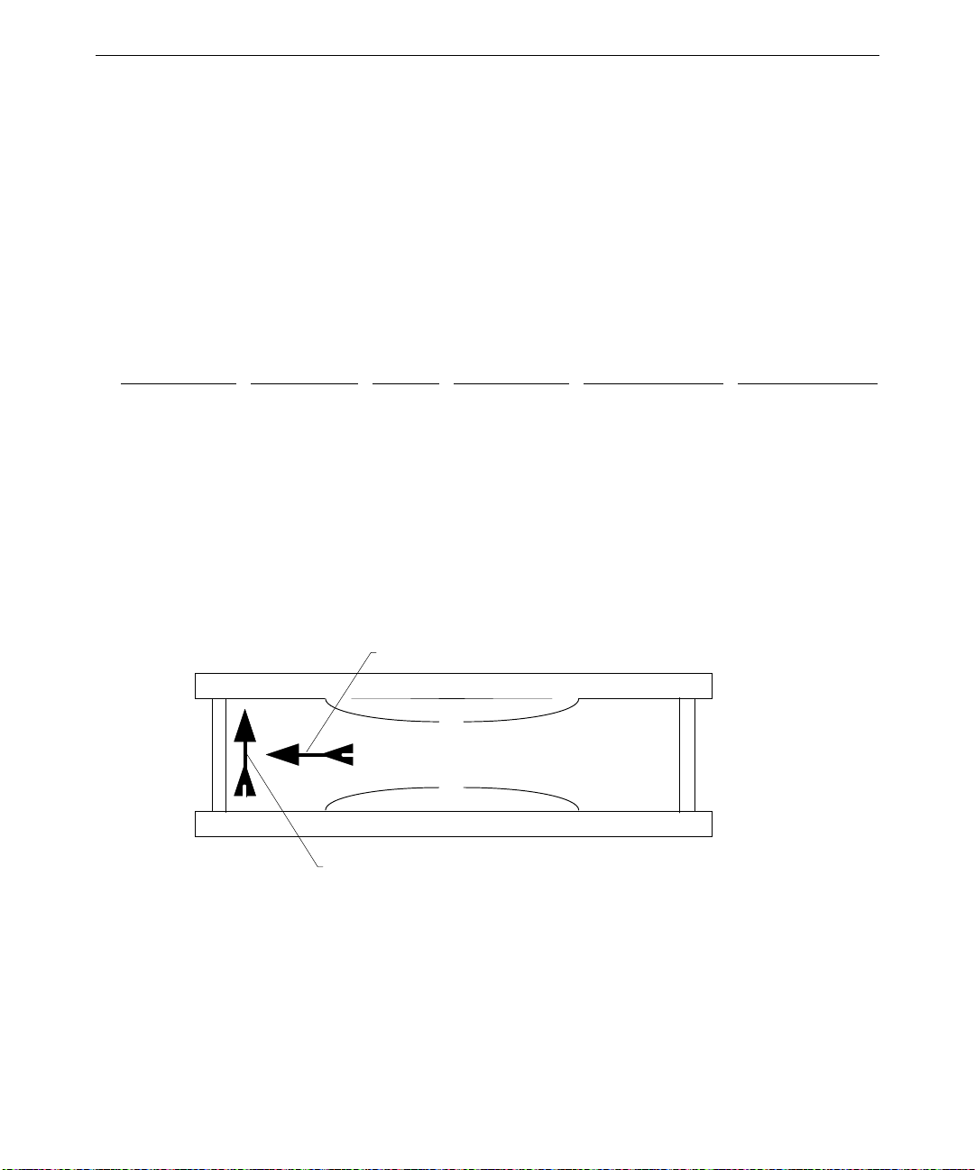
Cooling Fans
The TDZ 2000 has three cooling fans. One is inside the power supply; the others are
mounted in the chassis. All fans are 12 VDC. The fans pressurize the chassis and force
warm air out from the vents. Hardware controls the dynamic speed of each four-wire fan.
See Chapter 5, “System Board,” for connector locations and fan cable pinouts. See also
Chapter 2, “Servicing the System,” for details on replacing the chassis fans.
The table below summarizes fan information.
91
Fan
Chassis fan 1 Top rear 120 mm Back-to-front Processors, drives J5, system board
Chassis fan 2 Bottom front 120 mm Front-to-back Option cards J54, system board
Power supply Power supply 92 mm Back-to-front Power supply J39, system board
The two chassis fans (CFAN12009) are field replaceable.
The power supply fan is not field replaceable. If the fan requires replacement, you must
replace the power supply.
Arrows on each fan indicate airflow direction and rotation, as in the following illustration.
Location Size Airflow Devices Cooled Connector
Rotation
Side view of fan
Airflow
Ensure that you install each chassis fan with the airflow direction arrow pointing toward the
inside of the chassis.
Page 100

92
Dynamic Fan Speed Control
Hardware controls dynamic fan speed, based on temperature measured by a sensor and
whether the temperature is rising or falling. See “Temperature Sensors” below for additional
details.
The following table indicates the composite fan speed for four temperature setpoints. As the
temperature inside the chassis varies with the heat load, the fans change speed accordingly.
For example, if the temperature exceeds setpoint T1, composite fan speed increases to
medium low.
Temperature
Setpoint
T3—109.4° F (43° C)
T2—104° F (40° C)
T1—98.6° F (37° C)
T0—93.7° F (34° C)
The following table defines composite fan speeds used in the previous table.
Composite Fan Speed
High High High High
Medium High High High Low
Medium Low High Low Low
Low Low Low Low
Fan Speed (Composite)
Temperature Rising
High High
↑ ↓
Medium High High
↑ ↓
Medium Low Medium High
↑ ↓
Low Medium Low
↑ ↓
Low Low
Chassis Fan 1 Chassis Fan 2 Power Supply Fan
Fan Speed (Composite)
Temperature Falling
 Loading...