

Page 1

TDZ 2000
System Setup
February 1998
DHA023720
Page 2

Copyright
1998 Intergraph Computer Systems. All rights reserved. This document contains information protected by copyright, trade secret, and
trademark law. This document may not, in whole or in part, be reproduced in any form or by any means, or be used to make any
derivative work, without written consent from Intergraph Computer Systems.
Use, duplication, or disclosure by the United States Government is subject to restrictions as set forth in subdivision (c)(1)(ii) of the rights in
technical data and computer software clause at DFARS 252.227-7013. Unpublished rights are reserved under the copyright laws of the
United States.
Intergraph Computer Systems, Huntsville AL 35894-0001
Notice
Information in this document is subject to change without notice and should not be considered a commitment by Intergraph Computer
Systems. Intergraph Computer Systems shall not be liable for technical or editorial errors in, or omissions from, this document. Intergraph
Computer Systems shall not be liable for incidental or consequential damages resulting from the furnishing or use of this document.
All warranties given by Intergraph Computer Systems about equipment or software are set forth in your purchase contract. Nothing stated
in, or implied by, this document or its contents shall be considered or deemed a modification or amendment of such warranties.
Trademarks
Intergraph and the Intergraph logo are registered trademarks, and Ultra-Tower, TowerMate, TD, TDZ, Intense 3D, and RealiZm are
trademarks of Intergraph Computer Systems.
Microsoft, Windows, and Windows NT are registered trademarks of Microsoft Corporation.
Other brands and product names are trademarks of their respective owners.
FCC/DOC Compliance
This equipment has been tested and found to comply with the limits for a Class A digital device, pursuant to part 15 of the FCC Rules.
These limits are designed to provide reasonable protection against harmful interference when the equipment is operated in a commercial
environment. This equipment generates, uses, and can radiate radio frequency energy. If the equipment is not installed and used in
accordance with the instruction manual, it may cause harmful interference to radio communications.
Operation of this equipment in a residential area is likely to cause harmful interference in which case the user will be required to correct the
interference at his own expense.
This Class A digital apparatus meets all requirements of the Canadian Interference-Causing Equipment Regulations. Cet appareil
numérique de la classe A respecte toutes les exigencies du Règlement sur le materiél brouilleur du Canada.
Warnings
Changes or modifications made to the system that are not approved by the party responsible for compliance could void the user's authority
to operate the equipment.
To reduce the risk of electrical shock, do not attempt to open the equipment unless instructed. Do not use a tool for purposes other than
instructed.
There is a danger of explosion if the battery is incorrectly replaced. Replace the battery only with the same or equivalent type as
recommended by the manufacturer. Dispose of used batteries according to the manufacturer's instructions.
There are no user serviceable parts in the power supply. Refer all servicing of the power supply to qualified service personnel.
Notes
This device is designed and manufactured to comply with approved safety standards for information processing and business equipment.
Read all operating instructions before using this device. Keep these instructions for future reference. Follow all warnings on the device or
in the operating instructions.
Page 3

Contents
Preface............................................................................................................................... ix
About This Document......................................................................................................... ix
Document Conventions....................................................................................................... ix
Finding Operating System Information ................................................................................ x
Finding System Hardware Information................................................................................. x
Learning About System Ergonomics.................................................................................... x
Customer Support............................................................................................................... xi
1 Setting Up the Hardware................................................................................................ 1
Unpacking the System ......................................................................................................... 2
Placing System Components................................................................................................ 2
Setting Up the System.......................................................................................................... 3
Connecting an External SCSI Device................................................................................... 5
What’s Next?....................................................................................................................... 8
v
Hardware and Software Support Services.............................................................. xi
World Wide Web.................................................................................................. xi
Intergraph Bulletin Board Service ......................................................................... xi
FAXLink..............................................................................................................xii
Telephone ............................................................................................................ xii
More Support Options.......................................................................................... xii
SCSI Cable Length Guidelines............................................................................... 6
SCSI Cable Quality Guidelines............................................................................... 6
Device Connection................................................................................................. 7
2 Setting Up the Software.................................................................................................. 9
Preparing for Setup............................................................................................................ 10
Pre-Installed Software.......................................................................................... 10
Before You Start Setup......................................................................................... 10
Starting Operating System Setup........................................................................................ 12
Finishing System Setup...................................................................................................... 13
Creating a Repair Disk ......................................................................................... 13
Creating System Software Backup Diskettes......................................................... 13
What’s Next?..................................................................................................................... 14
3 Configuring the System................................................................................................. 15
Configuring the Video Display Driver................................................................................ 16
About RealiZm II Video Display Adapters........................................................... 16
Using the Display Properties Dialog Box.............................................................. 16
3D Display Performance and Full Drag (RealiZm II)............................................ 16
OpenGL Performance and Custom Cursors .......................................................... 17
Multiple Screen Display....................................................................................... 17
RenderGL Run-Time Library............................................................................... 17
Configuring RealiZm II Support for Heidi Graphics ............................................. 17
Page 4

vi
Correcting Video Display Problems...................................................................... 18
Configuring the Modem..................................................................................................... 19
Configuring Audio............................................................................................................. 20
Configuring Networking.................................................................................................... 20
Reassigning Hard Disk Drive Letters ................................................................................. 20
Changing Virtual Memory Settings.................................................................................... 21
Configuring SCSI Peripherals............................................................................................ 22
SCSI Configuration Utility Guidelines ................................................................. 22
Using the SCSI Configuration Utility ................................................................... 22
Getting Operating System Updates..................................................................................... 24
4 Configuring the BIOS................................................................................................... 25
Overview........................................................................................................................... 26
Starting AMIBIOS Setup................................................................................................... 26
Using AMIBIOS Setup...................................................................................................... 27
Setup Menu ....................................................................................................................... 27
Standard............................................................................................................... 27
Advanced............................................................................................................. 29
Chipset................................................................................................................. 32
PCI/PnP............................................................................................................... 34
Peripheral ............................................................................................................ 36
Utility Menu...................................................................................................................... 38
Language ............................................................................................................. 38
Detect IDE........................................................................................................... 38
Security Menu.................................................................................................................... 38
Supervisor, User................................................................................................... 38
Anti-Virus............................................................................................................ 39
Default Menu..................................................................................................................... 39
Original ............................................................................................................... 39
Optimal................................................................................................................ 39
Fail-safe............................................................................................................... 40
Reprogramming the BIOS.................................................................................................. 40
Assigning System Resources for Option Cards................................................................... 42
Changing the System Boot Sequence ................................................................................. 43
Summary of Default and Fail-Safe Settings........................................................................ 43
5 Operating Notes ............................................................................................................ 49
Moving the System............................................................................................................ 50
Opening and Closing the Door........................................................................................... 51
System Power, Startup, and Shutdown ............................................................................... 52
Using the Standby Button .................................................................................................. 53
Understanding System Power States................................................................................... 54
Automatic Shutdown Utility............................................................................................... 54
Starting the Automatic Shutdown Utility.............................................................. 54
Setting Time in the Automatic Shutdown Utility .................................................. 55
Configuring the Automatic Shutdown Utility ....................................................... 55
Page 5

vii
Using InterSite Programs................................................................................................... 56
Using Hardware Security Features ..................................................................................... 57
Finding Serial and Model Numbers.................................................................................... 57
Ensuring PC Card Support and Operation .......................................................................... 57
6 Troubleshooting............................................................................................................. 59
System Power.................................................................................................................... 60
System Boot....................................................................................................................... 60
Sound ................................................................................................................................63
Video................................................................................................................................. 63
Miscellaneous Hardware.................................................................................................... 64
Network............................................................................................................................. 64
7 Installing System Software............................................................................................ 65
Before You Begin.............................................................................................................. 66
System Software Products.................................................................................................. 67
Installing Windows NT Workstation 4.0 ............................................................................ 68
System Software................................................................................................... 68
Installation Guidelines ......................................................................................... 68
Installing QFE Software....................................................................................... 69
Reassigning Hard Disk Drive Letters.................................................................... 69
Changing Virtual Memory Settings ...................................................................... 70
Configuring SCSI Host Adapter Settings.............................................................. 70
Configuring PCMCIA Settings............................................................................. 71
Restoring a Pre-configured Striped Disk Set......................................................... 71
Configuring IDE/ATAPI Bus Mastering .............................................................. 72
Configuring the Sound Driver .............................................................................. 73
Getting Operating System Updates..................................................................................... 74
8 Using System Resources................................................................................................ 75
Available IRQs.................................................................................................................. 76
Freeing IRQs ..................................................................................................................... 76
PCI Devices....................................................................................................................... 76
Index................................................................................................................................. 77
Returned Goods Authorization (RGA) Form
Warranty Procedure
Repair Depot Address Labels
Page 6

viii
Page 7

Preface
TDZ 2000 System Setup describes setting up and configuring your TDZ 2000 system for use.
This document also provides information on operating the system, troubleshooting, and
reinstalling system software.
About This Document
TDZ 2000 System Setup is organized as follows:
u
Chapter 1, “Setting Up the Hardware,” describes how to set up the system hardware.
u
Chapter 2, “Setting Up the Software,” describes how to set up the operating system and
associated system software.
u
Chapter 3, “Configuring the System,” describes how to configure the system for use.
u
Chapter 4, “Configuring the BIOS,” describes how to use AMIBIOS Setup to configure
the system’s basic input/output system (BIOS).
u
Chapter 5, “Operating Notes,” describes how to use essential system features and
provides other important information.
ix
u
Chapter 6, “Troubleshooting,” describes how to resolve common system problems.
u
Chapter 7, “Installing System Software,” describes how to install the operating system
and associated system software, if required.
u
Chapter 8, “Using System Resources,” provides information on using system resources
to configure the system for use with additional option boards.
Document Conventions
Bold
Italic Variable values that you supply, or cross-references.
Monospace
SMALL CAPS Key names on the keyboard, such as D, ALT or F3; names of files and
CTRL+D Press a key while simultaneously pressing another key; for example, press
Commands, words, or characters that you key in literally.
Output displayed on the screen.
directories. You can type filenames and directory names in the dialog
boxes or the command line in lowercase unless directed otherwise.
CTRL and D simultaneously.
Page 8

x
Finding Operating System Information
For more detailed information on the operating system, see the printed and online Microsoft
documentation delivered with the system.
See the Late-Breaking News shipped with your system for important software and
documentation information not covered in this document.
Finding System Hardware Information
An online introduction to your new system is provided in the System Introduction, which
covers subjects such as the following:
u
System features
u
System controls and connections
u
Intergraph customer support
You can display the System Introduction by using the InterSite Welcome dialog or by
opening the
SYSINTRO.HLP file on your system.
Detailed reference information for your new system is provided in the System Reference,
which covers subjects such as the following:
u
Opening and closing the unit
u
Precautions against electrostatic discharges
u
Replacing and upgrading system components
u
Installing expansion cards
u
System interrupt requests (IRQs)
u
External port and system board connectors
u
System board jumpers
u
Power supply information
See the Late-Breaking News shipped with your system for important hardware and
documentation details not covered in this document.
Learning About System Ergonomics
Please read the Ergonomics Guide included with your Intergraph computer system. This
document provides valuable information on ways to minimize repetitive stress injuries for
persons working with a computer.
Page 9

Customer Support
Intergraph Computer Systems offers an assortment of customer support options.
Hardware and Software Support Services
Intergraph Computer Systems provides a variety of hardware services for Intergraph and
third-party equipment. Services include warranty upgrades, repair depot service, on-site
hardware maintenance, system administration, and network consulting. Hardware
purchased from Intergraph Computer Systems includes a factory warranty ranging from 30
days to three years. A detailed warranty description is available on the World Wide Web;
see the Support pages at http://www.intergraph.com/ics.
Intergraph Computer Systems provides complimentary software support for 30 or 90 days
following shipment of a hardware or software product. This includes World Wide Web
access, Intergraph Bulletin Board Service access, FAXLink service, and telephone (Help
Desk) support. At the end of the complimentary support period, you can purchase other
levels of software support.
World Wide Web
xi
You can visit Intergraph Computer Systems on the World Wide Web at
http://www.intergraph.com/ics. On these pages, you can get news and product
information, technical support information, software updates and fixes, and more.
Intergraph Bulletin Board Service
On the Intergraph Bulletin Board Service (IBBS), you can get technical support information,
software updates and fixes, and more.
To connect to the IBBS:
1. Set your system’s communications protocol for eight (8) data bits, no parity, one (1) stop
bit, and any baud rate up to 14,400.
2. Using a modem, call 1-205-730-8786. Outside the United States, call one of the mirror
sites listed on World Wide Web; see the Software Support pages at
http://www.intergraph.com.
3. At the login prompt, key in your user ID. If you have not connected before, key in new
to create a user ID.
4. Follow the menus to find what you need. The IBBS provides clear choices and online
help.
Page 10

xii
If you have trouble connecting to or using the IBBS, call the Customer Response Center at 1800-633-7248 (product entry IBBS) or leave a message for the IBBS System Operator at 1205-730-1413.
FAXLink
To use the FAXLink:
u
u
Telephone
To get customer support by telephone:
u
u
Call 1-800-240-4300 for information on how to get technical support information using
the FAXLink.
Call 1-205-730-9000 to get documents (up to five per call).
In the United States, call 1-800-633-7248 between the hours of 7:00 a.m. and 7:00
p.m. Central Time, Monday through Friday (except holidays).
Outside the United States, contact your local Intergraph Computer Systems subsidiary or
distributor.
Have the following information available when you call:
u
Your service number, which identifies your site to Intergraph Computer Systems. You
use your service number for warranty or maintenance calls.
u
Your Customer Personal Identification Number (CPIN). You get a CPIN the first time
you call the Customer Response Center; it is associated with your service number for
future call logging.
u
The product’s name or model number.
u
The product’s serial number. Software product serial numbers are included in the
product packaging. Hardware product serial numbers are on a sticker affixed to the
hardware product.
u
Your name and telephone number.
u
A brief description of the question or problem.
More Support Options
To get information on more customer support options:
u
Visit the Support pages on the World Wide Web at http://www.intergraph.com/ics.
u
For hardware support questions in the United States, call 1-800-763-0242.
Page 11

u
For software support questions in the United States, call 1-800-345-4856.
u
Outside the United States, contact your local Intergraph Computer Systems subsidiary or
distributor.
xiii
Page 12

xiv
Page 13

1 Setting Up the Hardware
Follow the instructions in this chapter to set up the hardware for your TDZ 2000
workstation.
Unpacking the System ......................................................................................................... 2
Placing System Components................................................................................................ 2
Setting Up the System.......................................................................................................... 3
Connecting an External SCSI Device................................................................................... 5
SCSI Cable Length Guidelines............................................................................... 6
SCSI Cable Quality Guidelines............................................................................... 6
Device Connection................................................................................................. 7
What’s Next?....................................................................................................................... 8
1
Page 14

2
Unpacking the System
CAUTION Carefully remove items from packaging. Do not drop any items on a hard surface, or
damage may result. You may need a helper to assist you in removing and placing heavy
items.
Remove everything from the shipping cartons, then look for the following items:
u
Workstation and power cord
u
Keyboard and mouse
u
Intergraph Computer Systems documentation
u
Windows NT Workstation 4.0 operating system software (CD-ROM and diskettes) and
documentation
u
Package containing screws for installing peripheral devices
If you purchased a monitor from Intergraph Computer Systems, its carton contains the
following:
u
Monitor and power cord
u
Video cable
u
Monitor documentation
NOTE If any of these items were not delivered, call the Customer Response Center immediately at
1-800-633-7248.
Save the packaging materials. If you need to return equipment for repair, it must be in its
original packaging for you to get warranty service.
If you have already unpacked and connected the peripherals to the system, go to Chapter 2 to
begin software setup.
Placing System Components
CAUTION Do not use the bottom portion of the face panel or the lip at the top rear of the unit as a hand
hold when moving the system. Equipment damage and personal injury can result.
When placing the system’s components, remember these guidelines:
u
Move and place the TDZ 2000 and monitor carefully.
u
Place the TDZ 2000 in a location where air can circulate freely around it. The front and
back panels should each have at least a 3-inch clearance.
Page 15

u
)
)
Avoid exposing the system to high levels of dust, smoke, or moisture.
u
Maintain a temperature range of 10 °C to 26 °C (50 °F to 80 °F); the optimum
operating temperature is 21 °C (70 °F).
u
Maintain a humidity range from 20 percent to 80 percent (non-condensing); the
optimum humidity level is 50 percent.
CAUTION Do not move the TDZ 2000 without first shutting down the system and turning off the power,
or damage to internal components may result. See Chapter 5 for instructions on properly
shutting down and powering off the system.
Setting Up the System
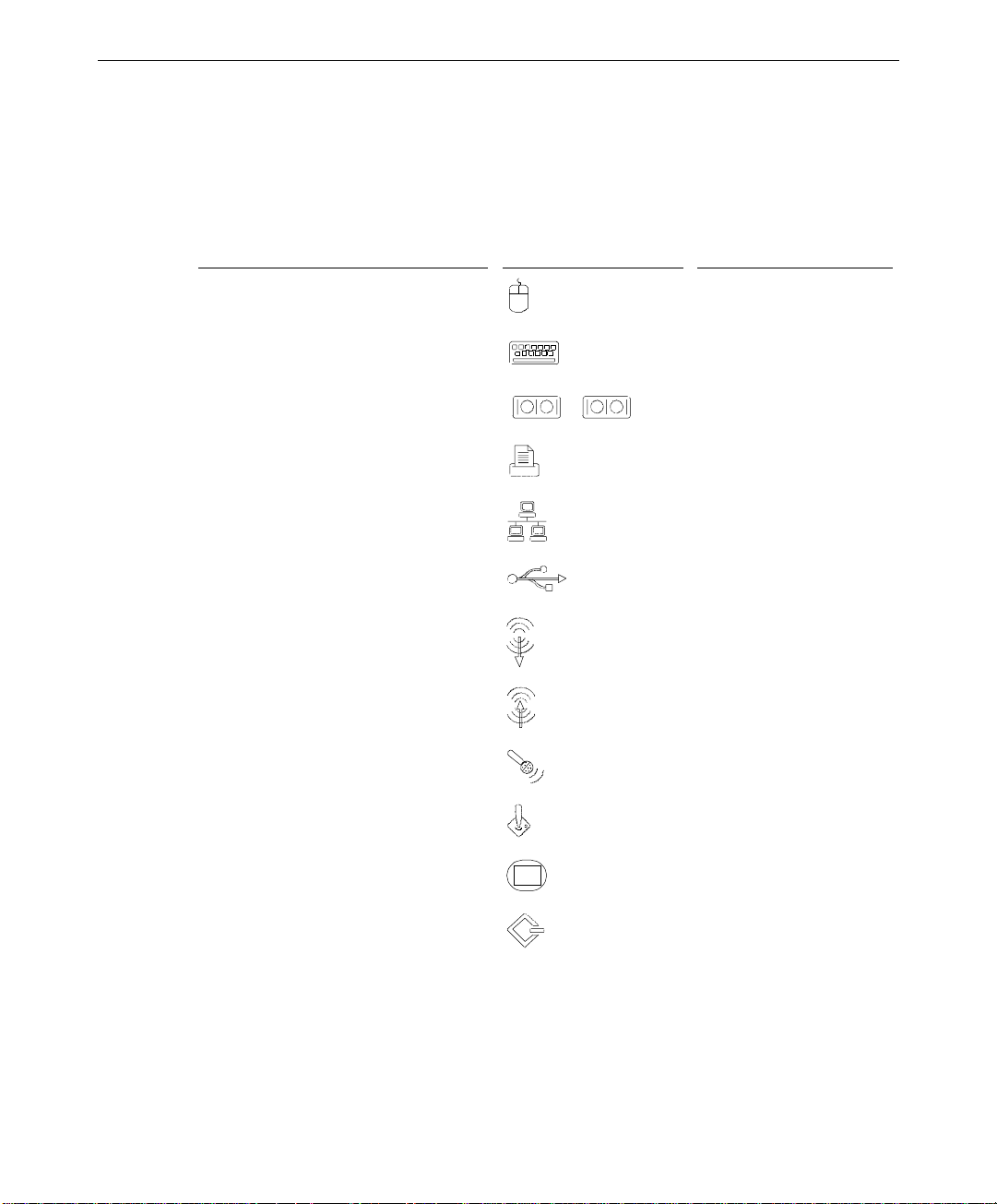
Before you connect any cables to the back of the TDZ 2000, note the connector locations in
the following illustration.
Keyboard
3
Mouse
Serial (COM 1
Parallel
Ethernet
Serial (COM 2
Universal Se rial Bus
Microphone
Audio Line In
Audio Line Out
MIDI/Game
Video Out
See the System Reference for technical details on each port.
Wide Ultra SCSI
(optional)
AC Line Out
AC Line In
Ultra SCSI
Page 16
4
To set up the system:
1. Arrange the system base unit, monitor, keyboard, and other peripherals in your
workspace.
2. Connect the cables from the various peripherals to the ports on the back of the system.
Connect the cable from this....
To the port labeled.... For this connector....
Mouse Mouse port
Keyboard
Modem, printer, or other device Serial (COM) port 1 or 2
1 2
Printer or other device
Network
Universal Serial Bus device
Stereo speakers or headphones;
Keyboard port
Parallel port
Ethernet port
Universal Serial Bus port
Audio Line Out port
Multimedia keyboard speaker
External stereo cassette or CD player;
radio or other device
Multimedia keyboard microphone
Audio Line In port
Microphone port
Game joystick or MIDI device
Monitor
External SCSI device
WARNING If you do not use cables supplied by Intergraph Computer Systems, you must use
shielded cables to prevent excessive electromagnetic interference (EMI). Intergraph
Computer Systems cables are designed to reduce the amount of EMI produced by the
system.
MIDI/Game port
Video Out port
SCSI port
Page 17

3. Connect any external SCSI devices to the appropriate SCSI port on the back of the
system. See “Connecting an External SCSI Device” below for details.
4. Connect the power cords from the monitor, system, and any external optional
peripherals, to receptacles on a grounded, three-prong AC wall outlet or an
uninterruptible power supply (UPS).
NOTE When you connect the computer power cord to the AC outlet, power is immediately applied to
the system. The system is always powered on when connected to AC power.
5. Open and stow the door on the front of the computer by doing the following:
−
Grasp the lip at the bottom of the door and lift up until the door is even with the top
of the system
−
Push the door into the system until the door stops
6. Stop! If you are not connecting external SCSI devices at this time, go to the section,
“What’s Next” at the end of this chapter.
Connecting an External SCSI Device
You may want to connect an external SCSI device, such as a hard disk or tape drive, to the
system. The TDZ 2000 features a standard external Ultra SCSI port. An external Wide
Ultra SCSI port is optional. Ultra SCSI provides a maximum data transfer rate of 20 MB per
second and Wide Ultra SCSI provides a maximum data transfer rate of 40 MB per second. If
you use a non-Ultra or non-Wide Ultra SCSI device, data transfer rates are limited to the
speed of that device.
5
Before you connect external SCSI devices to your system, read the following sections
carefully.
CAUTION Using a non-compliant SCSI-1 device with your system may cause your system to stop
working or lead to other unpredictable results.
CAUTION Make sure you shut down the system and unplug the power cord from the AC wall receptacle
before connecting or disconnecting any peripherals, including external SCSI devices.
NOTE See the
NOTE Most SCSI adapters do not recognize a hard disk drive that was formatted using a different
brand of adapter. For example, a hard disk drive formatted with an Adaptec SCSI adapter
will not work with a Symbios SCSI adapter. You must use only Symbios-formatted hard disk
drives with a Symbios SCSI adapter.
System Reference
for additional details on installing SCSI devices.
See “Configuring SCSI Peripherals,” in Chapter 3 for details on using the SCSI
Configuration Utility.
Page 18

6
SCSI Cable Length Guidelines
The number of drives and length of the cables used to connect the drives is a factor when
using SCSI-1, Fast SCSI (SCSI-2), Ultra SCSI, and Wide Ultra SCSI drives. Fast SCSI,
Ultra SCSI, and Wide Ultra SCSI impose shorter cable restrictions than SCSI-1. The total
length of the SCSI cabling must not exceed the following:
Connecting 1 to 4 Drives
SCSI-1 Fast SCSI-2 Ultra SCSI Wide Ultra SCSI
19.8 ft (6 meters) 9.9 ft (3 meters) 9.9 ft (3 meters) 9.9 ft (3 meters)
Connecting 5 to 7 Drives
SCSI-1 Fast SCSI-2 Ultra SCSI Wide Ultra SCSI
9.9 ft (3 meters) 9.9 ft (3 meters) 4.5 ft (1.5 meters) 4.5 ft (1.5 meters)
NOTE The SCSI controller (on the system board or an adapter card) counts as one device.
The total length of the SCSI cabling is the sum of the following:
u
Wide Ultra SCSI cable inside the system - 52 inches (132 cm)
u
Ultra SCSI cable inside the system - 14 inches (35.5 cm)
u
SCSI cable inside each device - 8 inches (20 cm)
u
SCSI cable between the system and the first device
u
SCSI cable between each device
SCSI Cable Quality Guidelines
To ensure data integrity and optimum performance, do the following:
u
Use only Intergraph Computer Systems SCSI cables. Cables from other vendors may
not provide adequate shielding.
u
Use the shortest cables possible to connect SCSI devices to the system and to each other.
Make sure the last device on a chain of external SCSI devices has an active SCSI terminator
connected to the open SCSI port. All other external SCSI devices must have SCSI
termination disabled or removed.
Page 19

Device Connection
The following steps provide basic information to connect a SCSI device to the system. See
the vendor documentation that came with the SCSI device for additional details on
installation, termination, and operation.
CAUTION Make sure you shut down the system and unplug the power cord from the AC wall receptacle
before connecting or disconnecting any peripherals, including external SCSI devices.
To connect an external SCSI device:
1. Shut down the system and unplug the power cord from the AC line receptacle.
2. Connect one end of the external SCSI cable to one of the following external ports on the
back of the system:
−
The standard Ultra SCSI port, located just under the AC Line Out connector
−
The optional Wide Ultra SCSI port, located on the right side of the I/O panel
3. Connect the other end of the cable to the SCSI device.
4. Set the SCSI ID of the device to an unused number between 1 and 6.
CAUTION Do not use ID 0 or ID 7. Using these IDs can cause system problems, including data loss.
7
5. Do one of the following:
−
If the device is the last or only device on the SCSI chain, enable SCSI termination
−
If the device is the first device or is between the first and last device on the SCSI
chain, disable SCSI termination
NOTE If the last or only SCSI device is not internally terminated, make sure you connect an active
SCSI terminator to the open SCSI port. All other external SCSI devices must have
termination disabled or removed.
6. Ensure that the power switch on the SCSI device is in the off position, and then connect
the power cord to the device and then to an AC receptacle.
7. Connect the TDZ 2000 power cord to the AC receptacle.
8. Turn on the power to the SCSI device and any other devices on the SCSI chain.
9. Press the Standby (power) button on the front panel of the TDZ 2000.
10. If necessary, install the software drivers and configure the drive according to the
vendor’s instructions.
Page 20

8
What’s Next?
Intergraph Computer Systems installs the operating system through Phase I of the process.
From here, you can do either of the following:
u
Continue the installation. See Chapter 2, “Setting Up the Software,” for instructions on
setting up the operating system and associated system software.
u
Reinstall the operating system. See Chapter 7, “Installing System Software,” for
instructions to install the software completely from CD-ROM.
NOTE Before starting the system for the first time, you may want to learn m ore about system power,
startup, and shutdown. See Chapter 5, “Operating Notes,” for this information.
Page 21

2 Setting Up the Software
Follow the instructions in this chapter to set up the operating system and associated system
software on your TDZ 2000 workstation.
Intergraph Computer Systems installs the operating system through Phase I of the process.
From here, you can do one of the following:
u
Continue the installation, as described in this chapter.
u
Reinstall the operating system. See Chapter 7, “Installing System Software,” for
instructions to install the software completely from CD-ROM and diskettes.
Preparing for Setup............................................................................................................ 10
Pre-Installed Software.......................................................................................... 10
Before You Start Setup......................................................................................... 10
Starting Operating System Setup........................................................................................ 12
Finishing System Setup...................................................................................................... 13
Creating a Repair Disk ......................................................................................... 13
Creating System Software Backup Diskettes......................................................... 13
What’s Next?..................................................................................................................... 14
9
Page 22

10
Preparing for Setup
Your system is equipped with a partitioned and formatted internal hard disk drive. Any
additional disk drives delivered with the system must be partitioned and formatted before you
can use them. See the operating system documentation and Help for information on
partitioning and formatting disk drives.
Pre-Installed Software
The operating system and associated system software is pre-installed on the primary hard
disk drive. Intergraph Computer Systems installed the following system software:
u
Driver software for the on-board SCSI adapter
u
Driver software for the on-board network adapter
u
Driver software for the installed video display adapter
u
Driver software for the on-board sound processor
u
Operating system network software (TCP/IP and NetBEUI)
u
Quick-Fix Engineering (QFE) update software (fixes for operating system problems or
limitations, if needed)
u
InterSite software
u
The default NT File System (NTFS) file system for standard configurations.
Before Y ou St art Setup
Before starting the Setup process, have the following documentation available:
u
The Microsoft Start Here document
u
Documentation for the video display adapter delivered with the system
Get and record the following information:
u
Your name, and the name of your
company or organization:
u
For a system running Windows NT,
the CD key from the Windows NT CD
case, or the Product ID Number from
Start Here or the registration card:
Page 23

If the system is connected to a network, get and record the following general information
from your network administrator:
u
Computer name for your system:
u
Workgroup name (if the system will be
part of a workgroup):
u
Domain name (if the system will be
part of a Windows NT domain):
If the system is connected to a network that uses the Transmission Control Protocol/Internet
Protocol (TCP/IP), get and record the following TCP/IP information from your network
administrator:
u
Internet Protocol (IP) address for your
system:
u
IP subnet mask for your system:
u
IP domain name for your network:
u
IP address for your network’s default
gateway:
11
u
IP addresses for your network’s
Domain Name System (DNS) servers,
if any:
u
IP addresses for your network’s
Windows Internet Name Service
(WINS) servers, if any:
Have several blank, formatted diskettes available to create backup diskettes containing
system software.
The Windows NT delivery media contain software and drivers for both Reduced Instruction
Set Computing (RISC)- and Intel-based systems. When installing Windows NT distribution
files, make sure you install them from the \
I386 directory (the Intel software directory) on the
delivery media. For example, if you are installing a device driver from the Windows NT
CD-ROM, key in the following when prompted for the path:
drive:\i386
where drive is the drive letter for the CD-ROM drive.
Page 24

12
Starting Operating System Setup
When you start your new TDZ 2000 for the first time, you must configure the operating
system software for use. After you first start the system, the Microsoft End User License
Agreement (EULA) screen displays.
NOTE Before starting the system for the first time, you may want to learn more about system power,
startup, and shutdown. See Chapter 5, “Operating Notes,” for this information.
To start the computer and set up the operating system software:
1. Turn on the monitor by pressing its power switch.
2. Open the system’s front panel door and press the Standby button (power switch). See
Chapter 1 for details. The system starts and the EULA screen displays.
3. Enter the Product Identification Number, found on the Certificate of Authenticity
included with your operating system documentation.
NOTE You must enter the Product Identification Number before you can continue Setup. You
cannot complete Setup if you do not enter the number.
4. Read the terms of the EULA and then follow the instructions displayed on-screen to
complete the Setup process. Accept the default settings provided by Setup, except as
follows:
−
Setup asks if you want to install networking. If you choose to install networking,
Setup detects the on-board network adapter and asks if you want to install the driver
software that it finds on the system disk. Allow Setup to install this driver software.
−
Create an Emergency Repair Disk when prompted.
−
ENTER or click OK at the logon dialog to log on to the operating system, if you
Press
do not create a user account during Setup.
−
Select the \
I386 directory if you are prompted for the location of Windows NT Setup
files, such as those for installing the video display adapter driver.
After you configure the video display, the sound processor, and networking, you can set up a
user account and join a workgroup or domain. See Windows NT Help for details on setting
up a user account and joining a workgroup or domain.
Page 25

Finishing System Setup
After operating system Setup is completed, an InterSite Welcome icon displays on the
operating system desktop. Double-click this icon, or select Programs/InterSite/Welcome
from the operating system Start menu, to display InterSite Welcome.
InterSite Welcome helps you do the following:
u
Create a repair disk for the operating system.
u
Create backup diskettes of device driver software and other system software products.
u
Display an online System Introduction for your system.
u
Learn about Intergraph Computer Systems customer support.
You should take advantage of the tools provided by InterSite Welcome to ensure that your
system is fully ready for use. See InterSite Welcome for more information. Also see the
following sections for information on creating a repair disk and creating backup diskettes.
Creating a Repair Disk
13
If you did not create an Emergency Repair Disk (Windows NT) or a Startup diskette
(Windows 95) during Setup, use the tools provided by InterSite Welcome to do so. The files
on these diskettes can restore the original contents of a damaged operating system Registry
(that is, at the time the operating system was installed), along with the standard operating
system drivers. You should also update an Emergency Repair Disk or a Startup diskette after
you finish configuring the system.
See the operating system documentation and Help for information on creating an Emergency
Repair Disk or a Startup diskette.
Creating System Software Backup Diskettes
Backup diskettes for some device driver software and system software products are not
delivered with the system. Use InterSite Version Manager, available through InterSite
Welcome, to create system software backup diskettes.
Version Manager lets you create backup diskettes containing device driver software and
system software products that were installed on the system before shipment, and which are
not available on the operating system CD-ROM. You may need these backup diskettes later
-- for example, if you have to reinstall a device driver or the operating system.
WARNING You must create system software backup diskettes after you set up the system
hardware and complete the operating system Setup program. If you do not do this,
Page 26

14
you may not be able to reinstall critical system software or the operating system if
needed.
NOTE You may not have to create backup diskettes for all system software. If Version Manager
does not list drivers or other system software products, they are available on the operating
system software CD-ROM or on backup diskettes delivered with expansion cards.
If the system requires Quick-Fix Engineering (QFE) update software, it is included in the
system software available for backup diskette creation. QFE update software contains fixes
for operating system problems or limitations, and is only shipped with the system if it is
needed. If QFE update software is shipped with the system, you should create a QFE backup
diskette for use if you have to reinstall the operating system.
See Version Manager Help for information on creating system software backup diskettes.
Visit the Intergraph Computer Systems site on the World Wide Web and vendor bulletin
boards for new and updated drivers.
What’s Next?
See the online System Introduction for information on system features and controls.
See Chapter 3, “Configuring the System,” to configure the system for use.
See Chapter 5, “Operating Notes,” for related details.
Page 27

3 Configuring the System
Follow the instructions in this chapter to configure your TDZ 2000 for use. This chapter
covers items required for basic operation.
Configuring the Video Display Driver................................................................................ 16
About RealiZm II Video Display Adapters........................................................... 16
Using the Display Properties Dialog Box.............................................................. 16
3D Display Performance and Full Drag (RealiZm II)............................................ 16
OpenGL Performance and Custom Cursors .......................................................... 17
Multiple Screen Display....................................................................................... 17
RenderGL Run-Time Library............................................................................... 17
Configuring RealiZm II Support for Heidi Graphics ............................................. 17
Correcting Video Display Problems...................................................................... 18
Configuring the Modem..................................................................................................... 19
Configuring Audio............................................................................................................. 20
Configuring Networking.................................................................................................... 20
Reassigning Hard Disk Drive Letters ................................................................................. 20
Changing Virtual Memory Settings.................................................................................... 21
Configuring SCSI Peripherals............................................................................................ 22
SCSI Configuration Utility Guidelines ................................................................. 22
Using the SCSI Configuration Utility ................................................................... 22
Getting Operating System Updates..................................................................................... 24
15
Page 28

16
Configuring the Video Display Driver
The first time you start the system, your monitor displays at 1024 x 768 screen resolution.
For the system to use the installed video adapter at other display resolutions, you must
configure the video display driver as described in this section.
NOTE RealiZm II is the only graphics system discussed in this document. If you purchased the
system with another graphics system, see the separate video display adapter documentation
for installation and configuration information.
About RealiZm II Video Display Adapters
RealiZm II video display adapters are 3D graphics accelerators. These graphics accelerators
provide a number of advanced graphics features, including hardware acceleration of OpenGL
and Windows NT graphics features, texture processing, and geometry acceleration. For
more information about RealiZm II graphics, see the video display adapter documentation
delivered with the system.
Using the Display Properties Dialog Box
Open Display in the Control Panel to configure the video display driver. Use the Settings tab
in the Display Properties dialog box to change the color depth, desktop size, font size, refresh
rate, and display type. To determine which video display adapter is installed on your system,
click the Display Type button. Use the controls on the Hardware Settings tab to change the
monitor type, screen display, and preferences.
For detailed information on configuring the video display driver, see the video display
adapter documentation and Help delivered with the system, and the
delivered with the video display drivers.
3D Display Performance and Fu ll Drag (RealiZ m II)
If you use 3D applications with the RealiZm II video display driver, the video display may
update slowly when you drag objects across it. To avoid this inconvenience, turn off full
drag before using 3D applications with these video drivers.
To turn off full drag:
1. Open Display in Control Panel.
2. Click the Plus! tab.
3. Click to deselect the Show Window Contents While Dragging checkbox.
4. Click OK.
README.TXT files
Page 29

OpenGL Performance and Custom Cursors
Windows NT features custom cursors, such as decorated or animated cursors, in place of the
standard cursor. If you use a custom cursor while running an OpenGL program,
performance may decrease whenever you position the cursor in that program’s window. For
optimum performance of OpenGL programs, Intergraph Computer Systems recommends
that you use only the standard cursors.
Multiple Screen Display
If your system is set up for dual- or triple-screen display, the video display driver treats the
combined display area as a single canvas that covers all screens. In this Full Canvas style,
windows centered on the canvas are split between screens. This includes most system dialog
boxes. For details, see the video display adapter documentation and Help delivered with the
system, and the
README.TXT files delivered with the video display drivers.
RenderGL Run-Time Library
The RenderGL run-time library is delivered with your TDZ 2000. This library is delivered
as a Dynamic Link Library (DLL) file. If you run an application that requires or uses the
RenderGL run-time library, you need to install the RenderGL DLL on your system.
17
The RenderGL DLL is delivered as follows:
•
Your system may have been delivered with a diskette containing the RenderGL DLL. If
so, see the
•
If your system was not delivered with a diskette containing the RenderGL DLL, you can
use the InterSite Version Manager to create the diskette. Run Version Manager from
the Welcome dialog that displays after you set up the operating system. After you create
the diskette, see the
For more information on the RenderGL run-time library, point your web browser to
http://www.intergraph.com and follow the links to the Digital Media home page. See
“Finding Intergraph Computer Systems on the Internet” in the Preface of this document for
further details.
README.TXT file on the diskette for installation instructions.
README.TXT file on the diskette for installation instructions.
Configuring RealiZm II Support for Heidi Graphics
The RealiZm II graphics accelerators support Heidi graphics for 3D Studio MAX. The Heidi
device driver, which operates in conjunction with the RealiZm II video display driver,
provides the support.
Page 30

18
The Heidi device driver is installed during installation of the RealiZm II video display
driver. After you install 3D Studio MAX on your system, copy the Heidi device driver file
GLZIHDD.HDI from the \SYSTEM32 directory to the \3DSMAX\DRIVER directory.
NOTE Use the version of the Heidi device driver that matches the version of the RealiZm II video
display driver.
See the README.TXT file delivered with the Heidi Device Driver for detailed instructions on
the driver and any associated files.
Correcting Video Display Problems
If the system’s video display is black, not synchronized, or distorted after you restart the
system, you may have a video configuration problem. Do not press
on to the Windows NT operating system. Instead, try to correct the problem by using the
Last Known Good option to return the system to the last know good configuration recorded
by Windows NT.
To use the Last Known Good option:
1. Restart the system.
CTRL+ALT+DELETE to log
2. Press the space bar at the following prompt:
Press space bar NOW to invoke the Last Known Good Menu
If using the Last Known Good option fails to correct the video display problems, you can
obtain a functional video resolution by restarting the system in VGA mode.
To restart the system in VGA mode:
1. Restart the system.
2. At the boot screen, select the VGA mode option appropriate for your system.
After logging on to Windows NT in VGA mode, check for the following common
configuration problems and solutions.
u
A multi-sync monitor is connected to the system, but a multi-sync monitor type is not
selected, and the display driver cannot determine this by querying the monitor. Select
an appropriate multi-sync monitor type.
u
A selected resolution, depth, or refresh rate is not supported by the multi-sync monitor.
Try using different video display settings.
u
The Dual Screen option is selected, but only one video board is detected. Deselect the
Dual Screen option.
Page 31

u
A multi-sync monitor is selected, but a monitor with different video timing (such as an
InterVue monitor) is connected to the system. Select the monitor that is connected to
the system.
u
The monitor selection is inappropriate for the multi-sync monitor attached to the system.
Restart the system in VGA mode, then select a new monitor as described previously.
u
A graphics resolution and color depth has been selected that exceeds installed display
memory. Restart the system in VGA mode, then open Display in the Control Panel to
reinstall and configure the display driver as described in the video display adapter
documentation delivered with the system.
Restart the system to use the reconfigured video display driver. If problems persist, contact
the Customer Response Center for help.
Configuring the Modem
If you must configure a modem for use with your system, you must ensure the BIOS settings
and modem jumpers are set appropriately, depending on which operating system and COM
port you want to use with the modem.
19
To configure the modem:
1. To use the modem with Windows NT, set the COM port jumper pins on the modem to
COM2. If that COM port is already in use, set the jumper to use a free COM port.
To use the modem with Windows 95, set the modem to Plug and Play mode according to
the vendor instructions included with the modem.
2. In the PCI/PnP menu in BIOS Setup, set the Boot to PnP Operating System parameter to
NO if the operating system is Windows NT, or to YES if the operating system is
Windows 95.
3. The modem requires a specific COM port. You must free system resources for use with
the modem in BIOS Setup. Set one of the Onboard Serial Port parameters to
DISABLED in the Peripheral menu in BIOS Setup, according to the following table:
Modem COM Port
Disable Onboard Serial Port
COM1 COM1
COM2 COM2
COM3 COM1
COM4 COM2
4. Set the remaining Onboard Serial Port parameter to AUTO and restart the system,
saving your changes.
Page 32

20
If configuring the modem under Windows NT, double-click the modem icon in Control
Panel. Use the Install New Modem window to automatically detect the installed modem.
Windows NT lists the name of the modem found.
If the listed modem is incorrect, you must install the appropriate driver for your modem,
located on the CD-ROM or floppy diskette media that accompanied the modem. Click
the Change button, then click the Have Disk button, and insert the driver media into the
appropriate drive. Follow the prompts to install the new driver.
Configuring Audio
The system is equipped with an on-board sound processor. Double-click the speaker icon in
the taskbar tray to display the audio mixer. See “Configuring the Sound Driver” in Chapter
7 for details on configuring the mixer for optimum sound quality.
Click the SRS icon in the taskbar tray to display the Crystal 3D Audio control. Adjust the
Center and Space sliders to control the audio effects. Right-click a Preset button to save the
settings.
Configuring Networking
The system is equipped with an on-board Ethernet network adapter. Before you configure
networking, ensure that the system is connected to the network.
If you did not install networking during Setup, you must install the network adapter driver
from a backup diskette to enable network operation. Use InterSite Version Manager to
create the
README.TXT file on the diskette for detailed installation instructions.
To configure Networking, open Network in the Control Panel. Follow the instructions in the
dialog boxes to set up the system to use a network. Be sure to set up the appropriate network
protocols, such as TCP/IP and NetBEUI, for the network to which the system is connected.
See the operating system documentation and Help for detailed information on setting up the
operating system to use a network.
INTELNETDRV backup diskette that contains the network adapter driver. See the
Reassigning Hard Disk Drive Letters
If you have more than one hard disk drive, you may need to reassign system drive letters.
You can also reassign the CD-ROM drive letter, if needed.
Page 33

To change drive letters:
1. From the Start menu, click Programs, Administrative Tools, and then Disk
Administrator.
2. Select a hard disk drive.
3. From the Tools menu, click Assign Drive Letter.
NOTE If you select the current drive or an otherwise locked drive, you must restart the system to
complete the drive letter reassignment.
4. Select a new drive letter to assign to the hard disk drive from the list. Click OK, and
then click Yes to continue.
5. If necessary, click OK, and then click Yes.
6. Repeat steps 2 through 4 for each hard disk drive letter assignment that you want to
change.
7. Click Partition, then click Exit. If necessary, restart the system to complete the drive
letter reassignments.
Changing Virtual Memory Settings
21
If you have more than one hard disk drive, you may need to change size and location of your
virtual memory page file. See Windows NT Help for more information.
Consider the following before changing page file settings:
u
The size of the page file. If your system is equipped with a large amount of RAM, Setup
might create a page file that is unnecessarily large.
u
Drive letter reassignments. If you reassigned your drive letters, you may find it
necessary to adjust your page file settings.
To change the size and location of the virtual memory page file:
1. From Start, click Settings, and then click Control Panel.
2. Double-click the System icon.
3. Click the Performance tab and then click Change.
4. Click a drive letter in the list, and then type new values in the Initial Size and Maximum
Size text boxes.
5. Click Set.
6. Repeat steps 4 and 5 for any additional drives in the list.
7. Click Close, then click OK. An alert box displays.
Page 34

22
8. Do one of the following:
−
Click Yes to restart the system with the new settings.
−
Click No to continue with other tasks and use the new settings the next time you
restart the system.
Configuring SCSI Peripherals
You may need to use the SCSI Configuration Utility, delivered on the SYSUTIL diskette, to
configure your SCSI peripherals under certain conditions. This software is also available
from the Intergraph Bulletin Board Service (IBBS) or Intergraph Online. See “Using the
Intergraph Bulletin Board Service” and “Finding Intergraph on the Internet” in the Preface
of this document for details.
SCSI Configuration Utility Guidelines
The SCSI Configuration Utility allows you to configure the SCSI host adapter, perform a
low-level format on a SCSI hard disk drive, select boot order, and verify media. You should
change only the synchronous data transfer rate parameter. This parameter defines the rate at
which data is transferred among SCSI devices; for example, 40 MB per second (default).
Change the SCSI host parameters on a per-device basis under the following conditions:
u
If you are advised to do so by Intergraph technical support or instructed to do so by the
vendor documentation supplied with the SCSI device.
u
If the SCSI device does not negotiate properly with the controller. This is common on
older drives.
u
If you exceed the total cable length for connecting SCSI devices to the system, as
specified in the section, “Understanding SCSI Guidelines,” in Chapter 1.
u
If you connect non-Ultra or non-Wide Ultra SCSI external devices to the system.
NOTE Most SCSI adapters do not recognize a hard disk drive that was formatted using a different
brand of adapter. For example, a hard disk drive formatted with an Adaptec SCSI adapter
will not work with a Symbios SCSI adapter. You must use only Symbios-formatted hard disk
drives with a Symbios SCSI adapter.
Using the SCSI Configuration Utility
NOTE Change the synchronous data transfer rate or the data width parameters for an individual
device only. Do not change the parameters for the SCSI host adapter itself. Changes to the
SCSI host adapter affect all devices on its bus.
Page 35

When using the SCSI Configuration Utility, remember the following keyboard tips:
u
Press the up or down arrow keys to move about in the menus.
u
Press ENTER to confirm a menu selection.
u
Press ESC to cancel a selection.
u
Select Help to display a Help screen with instructions and details.
To change the synchronous data transfer rate:
1. Insert the SYSUTIL diskette in the floppy drive.
2. From the Start menu, click Shut Down. The Shut Down Windows dialog box displays.
3. Click Restart and then click OK. The system restarts and the MS-DOS 6.22 Startup
Menu displays.
23
4. Select SCSI Configuration Utility and press
ENTER.
5. From the main menu, select the SCSI host adapter that you want to configure and press
ENTER. Two SYMB53C875 SCSI host adapters, one for each channel, are listed. Port
EC00 is the external bus; port E800 is the internal bus.
6. From the Utilities menu, select Device Selections and press
ENTER.
7. From the Device Selections menu, select the SCSI device that you want to configure and
ENTER.
press
NOTE Only eight SCSI devices are listed at a time. Select Device Selections 8-15 to list the next
eight SCSI devices.
NOTE If the device that you want to configure is not listed, exit the menu, repeat step 5 and select
the other host adapter. Then, continue with step 6.
8. Select Sync Rate (Megabytes/sec) and press ENTER.
9. Select the appropriate rate (Off, 10, 20, or 40) and press
and then press
ENTER.
10. From the Device Selections menu, select Exit This Menu and press
11. From the Utilities menu, select Exit This Menu and press
ENTER, select Exit This Menu,
ENTER.
ENTER. The Save/Cancel
menu displays.
12. Select Save Changes and press
ENTER.
13. Eject the diskette from the floppy drive and press any key to restart the system.
Page 36

24
Getting Operating System Updates
Microsoft Service Packs contain the latest improvements and system fixes for Microsoft
operating systems. Service Packs are created by Microsoft for post-release support. You can
get Service Packs from the Microsoft World Wide Web and FTP sites free of charge.
CAUTION If Intergraph Computer Systems provides a Service Pack through the IBBS or
with a product or system, it has been certified against Intergraph Computer Systems
hardware as described in the announcement of its availability. If you obtain a Service Pack
from any other source, be aware that it may not be certified against your Intergraph
Computer Systems hardware.
Page 37

4 Configuring the BIOS
This chapter tells how to use AMIBIOS Setup and the Flash Programming Utility (FPU or
FLASHPROG). Use the information in this chapter if you want to configure some aspects of
system operation by changing the basic input/output system (BIOS) settings, or by updating
the BIOS to take advantage of enhancements provided by Intergraph Computer Systems.
Overview........................................................................................................................... 26
Starting AMIBIOS Setup................................................................................................... 26
Using AMIBIOS Setup...................................................................................................... 27
Setup Menu ....................................................................................................................... 27
Standard............................................................................................................... 27
Advanced............................................................................................................. 29
Chipset................................................................................................................. 32
PCI/PnP............................................................................................................... 34
Peripheral ............................................................................................................ 36
Utility Menu...................................................................................................................... 38
Language ............................................................................................................. 38
Detect IDE........................................................................................................... 38
Security Menu.................................................................................................................... 38
Supervisor, User................................................................................................... 38
Anti-Virus............................................................................................................ 39
Default Menu..................................................................................................................... 39
Original ............................................................................................................... 39
Optimal................................................................................................................ 39
Fail-safe............................................................................................................... 40
Reprogramming the BIOS.................................................................................................. 40
Assigning System Resources for Option Cards................................................................... 42
Changing the System Boot Sequence ................................................................................. 43
Summary of Default and Fail-Safe Settings........................................................................ 43
25
Page 38

26
Overview
The BIOS records basic system operating parameters, such as the amount of memory, the
boot sequence, and the type of video display. The operating parameters are set in the BIOS
before shipment.
The BIOS is stored in flash erasable-programmable memory (EPROM) on the system board,
and reads the system parameters in the system’s complementary metal-oxide semiconductor
(CMOS) random-access memory (RAM). When you power off the system, a lithium battery
provides power to CMOS RAM to retain the operating parameters. Each time you power on
the system, the BIOS uses stored parameters to configure the system.
The AMIBIOS Setup program, which is also stored in the flash EPROM on the system
board, allows you to manually change the system operating parameters. The Flash
Programming Utility (FPU or FLASHPROG) allows you to update the BIOS.
The AMIBIOS Setup menus and options discussed in this chapter are for BIOS 841xx.
ROM, where xx is the version. The BIOS version number displays as the system starts. The
message is similar to the following:
AMIBIOS (C) 1997 American Megatrends Inc.,
(C) 1997 Intergraph Corporation (841xx)
For a summary list of all the parameters and their settings, refer to the section “Summary of
Default and Fail-Safe Settings” at the end of this chapter.
St arting AMIBIOS Setup
To start AMIBIOS Setup:
1. Restart the system. The following message displays:
Press DEL to enter Setup
2. Press
This screen allows access to menus for configuring the BIOS to suit your own needs or
perform maintenance as needed. The following sections describe the parameters you can
access through each menu.
NOTE You can set a password to prevent unauthorized users from accessing AMIBIOS Setup. See
“Security Menu” in this chapter.
DELETE. The AMIBIOS Setup Main Menu displays.
Page 39

While using AMIBIOS Setup, remember these tips:
u
To access Help, press ALT+H. The Keystroke/Mouse Convention list displays, which
explains how to select Setup menu items with the mouse pointer and with keys. Press
any key to close the list and return to AMIBIOS Setup.
u
To change a parameter’s value, move the pointer to a parameter and click the mouse
button. An Options menu displays and allows you to select one of the choices.
u
When you are in the main menu in AMIBIOS Setup, press ESC to exit. The Save
Changes and Exit option highlights; press
in the program will be saved. If you select the Continue option, then you will return to
AMIBIOS Setup.
Using AMIBIOS Setup
The AMIBIOS Setup menu allows you to change most of the BIOS settings. The following
section describes the parameters grouped in the AMIBIOS Setup menu. Which parameters
are available depends on your system configuration and your status as Supervisor or User.
27
ENTER to exit. Any changes you made while
Setup Menu
Standard
The Standard Setup menu allows you to set the IDE drive parameters, set the system date
and time, and define floppy disk drive parameters.
Primary Master, Primary Slave, Secondary Master, Secondary Slave
These icons represent parameters for Integrated Device Electronic (IDE) drives. If installing
IDE hard drives, use the Detect IDE utility to automatically detect and configure the drives.
See “Utility Menu” in this chapter for more information.
To change the Primary/Secondary Master or Primary/Secondary Slave parameters:
1. Select Primary/Secondary Master or Primary/Secondary Slave.
2. Select USER from the list of drive types.
3. Select each of the following parameters and enter the appropriate values. For more
information, see the documentation included with the device.
Page 40

28
Parameter Description
CYL Cylinders
HD Heads
WP Write Precompensation
LZ Landing Zone
SEC Sectors
4. When complete, press
ESC or click the close box at the upper left corner of the window.
Date/Time
Select the Date/Time icon to display the current system date and time values.
To change the system date and time:
1. Click the incorrect value with the mouse pointer or press the
highlights.
2. Click the + or - buttons to change the value, or enter the correct value from the
keyboard.
NOTE The time displays in 24-hour format.
3. Press ESC to save the new values and return to Standard Setup.
Floppy A, Floppy B
The Floppy A and Floppy B icons allow you to specify the type of floppy disk drive installed
in the system.
The floppy disk drive A parameter is preset to 1.44 MB 3.5-inch. Do not change the
parameter unless you replace floppy drive A with a different capacity disk drive.
The floppy disk drive B parameter is preset to Not Installed, unless an optional drive has
been installed before shipment. Do not change the parameter unless you install an optional
floppy disk drive.
TAB key until the value
To change the floppy drive parameters:
1. Select the Floppy A or Floppy B icon.
2. Press the up and down arrow keys or click in a box to select the correct parameter for the
floppy disk drive.
3. Press
ENTER to accept the change, or click the close icon in the upper left corner of the
floppy disk drive configuration menu.
Page 41

Advanced
The Advanced Setup menu allows you to change details of the system’s operation. Each
parameter included in the Advanced Setup menu is described below.
1st - 4th Boot Device (Supervisor)
These parameters specify the device sequence for system boot up. The default is SCSI (1st),
Floppy (2nd), CDROM (3rd), which means the system attempts to boot from drive C first. If
unsuccessful, it attempts to boot from drive A. If unsuccessful, it attempts to boot from the
IDE CD-ROM drive. By default, C: is the system hard disk drive and A: is the floppy disk
drive. Disable the 1st Boot Device parameter to boot the system from a diskette in the floppy
disk drive. To boot from the CD-ROM drive automatically, disable both the 1st and 2nd
Boot Device parameters. These parameters can be modified only by the Supervisor.
Try Other Boot Devices
This parameter enables the system to boot from the network if attempts to boot from the
devices listed in the 1st - 4th Boot Device parameters are unsuccessful. The default is Yes.
Above 1 MB Memory Test
29
When enabled, this parameter invokes the Power On Self Test (POST) memory routines on
the RAM above 1 MB. If disabled, the BIOS will check only the first 1 MB of RAM. The
default is Enabled.
Floppy Access Control (Supervisor)
This parameter allows you to set the floppy device to read-only access. The default is ReadWrite.
IDE Hard Disk Access Control (Supervisor)
This parameter allows you to set IDE Hard Disk devices to read-only access. The default is
Read-Write.
PS/2 Mouse Support
When set to Enabled (default), the BIOS supports a PS/2 mouse using IRQ12. When set to
disabled, a serial mouse, using the appropriate serial port IRQ, must be used to provide
mouse input.
Page 42

30
System Keyboard
This parameter enables or disables BIOS keyboard testing. Acceptable values are Absent
and Present. If Present (default) is selected, the BIOS tests for the keyboard when the system
boots and provides an error message if the keyboard is not present. If Absent is selected, the
BIOS does not test for the presence of a keyboard.
Typematic Rate
This parameter defines the rate at which a keystroke repeats when you press and hold down a
key. Accepted values are Slow or Fast (default).
System Boot Up Num Lock
This parameter, when set to On (default), disables the arrow keys on the numeric keypad.
The Num Lock option on the keyboard can be turned off and on while the system is
operating.
Wait for ‘F1’ on Error
When set to Enabled (default), the system will display a Press <F1> to RESUME
message if an error occurs during boot up diagnostic tests. If this setting is Disabled, any
non-fatal errors will not generate the statement, but the AMIBIOS will display the
appropriate error message.
Hit ‘DEL’ Message Display
When set to Enable (default), the system provides a message during boot that the AMIBIOS
Setup program can be accessed by pressing the
DELETE key. Disabling this parameter
prevents the message from displaying.
Floppy Drive Seek at Boot
When set to Enabled, AMIBIOS performs a Seek command on floppy disk drive A before
booting the system. The default is Disabled.
Password Checking (Supervisor)
This parameter prevents unauthorized system boot up or use of AMIBIOS Setup. Setup (the
default) enables the system to prompt for a password before allowing you to enter AMIBIOS
Setup. If you select Always, the password prompt appears each time the system is powered
on. This parameter can be modified only by the Supervisor.
Page 43

31
OS/2 Compatible Mode
When set to Yes, this setting optimizes the system for use with OS/2. The default is No.
Processor Microcode Update (Supervisor)
This parameter allows to you disable an installed processor patch, if the patch causes the
system to operate improperly. Any patch installed by Intergraph Computer Systems has been
certified for use with the system, so this parameter is set to Enabled by default. Use Disabled
if a non-Intergraph Computer Systems certified patch is applied and problems occur. This
parameter can be modified only by the Supervisor.
L1 and L2 Cache Mode
Allows you to choose between two processor cache modes: WriteBack (default) and
WriteThru.
L2 Cache ECC Mode
This parameter, when enabled, allows error checking and correction in the Level 2 cache in
the processor subsystem. Enabling ECC Mode can slow system performance. The default
for this parameter is Disabled.
System BIOS Cacheable
Setting this parameter to Enabled (default) makes the BIOS code cacheable, which improves
overall system performance.
x
000, 16K Shadow
C
When the system boots, the BIOS code on ISA adapters is used directly from ROM
(Disabled), or it is copied from the board’s ROM to system RAM. Overall system
performance improves when copied to RAM (Enabled). When set to Cached (default), the
BIOS is copied to RAM and cached, further improving performance. An ISA board BIOS
executes faster from system board RAM than from the ISA board ROM. All of the ISA
Adapter ROM parameters are set to Cached by default.
x
000, 16K Shadow
D
When the system boots, the BIOS code on ISA adapters is used directly from ROM
(Disabled, the default setting), or it is copied from the board’s ROM to system RAM.
Overall system performance improves when copied to RAM (Enabled). When set to Cached,
the BIOS is copied to RAM and cached, further improving performance. An ISA board
BIOS executes faster from system board RAM than from the ISA board ROM. All of the
ISA Adapter ROM parameters are set to Disabled by default.
Page 44

32
Chipset
The Chipset Setup menu contains the parameters that affect the functionality of some
hardware components.
On-Board SCSI Controller (Supervisor)
When set to Enabled (default), this parameter activates the on-board, PCI-based SCSI
controller. The SCSI controller can be disabled by changing the value to Disabled. This
parameter can be modified only by the Supervisor.
On-Board Network Controller (Supervisor)
This parameter enables or disables the network processor circuitry on the system board. The
default is Enabled.
On-Board Sound Controller
This parameter enables or disables the sound processor circuitry on the system board. The
default is Enabled.
USB Function
When set to Enabled (default), this parameter activates the system’s two Universal Serial
Bus (USB) ports.
H/W Monitor, Primary I/O Port
This parameter controls the I/O port used by the Hardware Monitor. The default is 110119h. Options are 210h-219h and 310h-319h.
H/W Monitor, Secondary I/O Port
This parameter controls the I/O port used by the Hardware Monitor. The default is 210217h. Options are 110-119h and 310h-319h.
NOTE The Primary and Secondary Ports must be set to separate values. Setting both ports to the
same value will disable the Hardware Monitor.
H/W Monitor, IRQ
This parameter controls which IRQ the Hardware Monitor uses. The default is IRQ 15.
Options are 5, 7, 10, 11, and 15.
Page 45

Build MPS Table for Uniprocessor
When this parameter is set to Yes, the BIOS enables single-processor systems to use the
multi-processor kernel. The default is No.
Memory Data Integrity Mode
ECC mode (default) provides error correction for data stored in memory. Parity mode
provides error detection for data stored in memory. The other setting is None.
Fixed Memory Hole
When set to Enabled, this parameter allows the memory in a RAM option card to be patched
into a specific location in the system’s memory, to accommodate ISA cards requiring a fixed
range of addresses. The default is Disabled. Options are 512KB-640KB and 15MB-16MB.
Generate NMI on System Error
This parameter halts the system when a catastrophic error is detected. This prevents the
error from corrupting your data. The default is Enabled.
33
AGP Aperture Size
The default is 64 MB. Options are 4 MB, 8 MB, 16 MB, 32 MB, 64 MB, 128 MB, and
256 MB.
VGA Frame Buffer USWC Mode
When enabled, the system performs write combining on VGA write commands. This
reduction in the amount of data written to the display improves system performance by
reducing the amount of bus traffic. The default is Disabled.
First Type F DMA
When set to Enabled, this parameter allows the system to transfer data to an ISA option card
at a faster rate than normal. However, the ISA option card must support Type F DMA
transfers. The default is Disabled.
First Type F DMA Channel
This parameter selects which DMA channel is used for Type F DMA transfers with the first
ISA option card. Not available (grayed) by default.
Page 46

34
PCI/PnP
Second Type F DMA
When set to Enabled, this parameter allows the system to transfer data to an second ISA
option card at a faster rate than normal. However, the ISA option card must support Type F
DMA transfers. The default is Disabled.
Second Type F DMA Channel
This parameter selects which DMA channel is used for Type F DMA transfers with the
second ISA option card. Not available (grayed) by default.
DMA Channel x Type
This parameter specifies the functionality of the selected DMA channel. Select from Normal
ISA, PC/PCI, or Distributed modes. The default is Normal ISA.
The PCI/PnP Setup menu contains the parameters that affect the DMA channels, IRQs, and
PCI and PnP components.
Boot to PnP Operating System
When this parameter is set to No (the default), the BIOS initializes all devices during boot
up. When set to Yes, the BIOS only performs the amount of initialization required to load
the Plug-and-Play operating system. Any other device initialization must then be performed
by the PnP operating system.
PCI 2.1 Latency Compliance
When Enabled (default), this parameter sets the system to be PCI 2.1 compliant.
PCI Latency Timer (PCI Clocks)
This parameter sets the PCI clock latency timing for PCI devices. The default is 40h.
PCI VGA Palette Snoop
This parameter allows palette data from an installed PCI graphics board to be shared with an
installed ISA graphics board. Since the graphics delivered with the system are PCI-based,
this option is set to Disabled by default.
Page 47

Allocate IRQ to PCI VGA
When set to No, this parameter frees an IRQ which otherwise would have been allocated to
the PCI VGA card. The default is Yes.
PCI IDE Bus Mastering
When set to Disabled, this parameter deactivates the bus mastering capability of the PCI IDE
controller. The default setting is Enabled.
Use ESCD for PCI IRQ Assignment
If this parameter is set to Yes, when the system boots, it reads ESCD data to determine how
to assign IRQs to system devices and option cards. You can use PnP operating systems to
manipulate this ESCD data to assign specific IRQs to specific system devices and option
cards on subsequent system boots. When the parameter is set to No (default), you can use
the BIOS to assign IRQs to PCI devices regardless of ESCD instructions.
PCI Slot x IRQ Priority
Use this parameter to assign specific IRQs to specific PCI cards when ESCD data is not
being used. The default is Auto. Options are 3, 4, 5, 7, 10, 11, 12, 14, and 15.
35
DMA Channel x Usage
This parameter specifies whether a given DMA channel is to be reserved for an ISA card, or
is free to be assigned to another device by the PnP BIOS. The options are PnP (default) and
ISA.
IRQ x Usage
This parameter specifies whether a given IRQ is to be reserved for an ISA card, or is free to
be assigned to another device by the PnP BIOS. The options are PCI/PnP (default) and ISA.
ISA Reserved Memory Size
Use this parameter in conjunction with the ISA Reserved Memory Address parameter to
allocate a fixed amount of memory for ISA cards that require a specific amount of memory
and a set memory location. The memory size you select limits the memory addresses
available to assign to ISA cards. The default is Disabled.
ISA Reserved Memory Address
Use this parameter in conjunction with the ISA Reserved Memory Size parameter to allocate
a fixed amount of memory for ISA cards that require a specific amount of memory and a set
Page 48

36
memory location. The memory addresses available depend on the memory size you select.
The default is D0000.
Peripheral
The Peripheral Setup menu has parameters that affect option boards, serial ports, and
parallel port functionality.
OnBoard FDC
When set to Enabled (the default), this parameter enables the system floppy disk drive I/O
controller on the system board. If you install floppy controller cards, then this parameter
must be set to Disabled.
OnBoard Serial Port1
This parameter enables the use of serial port 1 on the system board by selecting a memory
address for the port. The values are Disabled, 3E8H, 3F8H, 2E8H, and Auto. The default is
Auto. The addresses correlate to a COM port number as defined by the following table.
Serial Port
COM1 3F8-3FF IRQ4
COM2 2F8-2FF IRQ3
COM3 3E8-3EF IRQ4
COM4 2E8-2EF IRQ3
OnBoard Serial Port2
This parameter enables the use of serial port 2 on the system board by selecting a memory
address for the port. The values are Disabled, 3E8H, 2F8H, 2E8H, and Auto. The default is
Auto. The addresses correlate to a COM port number as defined by the previous serial port
table.
Serial Port 2 Mode
This parameter enables Infra-Red functionality on serial port 2. Select from Normal, IrDA,
or IR. Normal is the default setting. Use the IR Transmission Mode, Receiver Polarity, and
Transmitter Polarity to control the characteristics of the serial port when using Infra-Red
capability.
Addresses Interrupts
Page 49

OnBoard Parallel Port
This parameter enables the use of the parallel port by selecting a memory address. The
values are Disabled, 278H, 378H, 3B8H, and Auto. The default is Auto. The addresses
correlate to an LPT port number as defined by the following table.
37
Parallel Port
Address Interrupt
LPT1 378-37A IRQ7 or IRQ5
LPT2 278-27A IRQ7 or IRQ5
LPT3 3BC-3BE IRQ7 or IRQ5
Parallel Port Mode
This parameter allows you to change the parallel port mode setting. The values are Normal
(default), EPP, and ECP. When set to ECP, the ECP DMA Channel parameter activates.
EPP Version
If the Parallel Port Mode is set to EPP, you can select two EPP protocol versions: 1.7 and
1.9 (default).
Parallel Port IRQ
This parameter allows you to select a base IRQ for the parallel port. The default is IRQ7, or
IRQ5 may be selected. Either IRQ can be assigned to any of the LPT port numbers as shown
in the previous onboard parallel port table.
Parallel Port DMA Channel
This parameter activates when the Parallel Port Mode is set to ECP. You can select a DMA
channel for the parallel port when operating in ECP mode. Values for this parameter are
None, and CH 1 through CH 7. When the Parallel Port Mode is set to ECP, the default
DMA channel is 3.
On-Board IDE
When set to Disabled, this parameter deactivates the on-board IDE controller, allowing you
to use both channels of a PCI IDE controller option card. The default is Primary. Options
are Disabled, Primary, Secondary, and Both.
Page 50

38
Utility Menu
Use the following utilities to change the language used in BIOS Setup, and to automatically
detect and configure any IDE drives you connect to the system. For information on setting
an IDE device to master or slave, see the documentation accompanying the device.
Language
The default is English.
Detect IDE
This parameter searches for IDE devices connected to the IDE controller. Any IDE drive
found is then made available for you to configure.
Security Menu
The Security Menu allows you to change the system password for the Supervisor and the
User.
Supervisor, User
To prevent unauthorized users from accessing the AMIBIOS Setup program, you can enter a
password on both of the Supervisor and User menus. If you do not enter a password, then
the system will not prompt users for a password when they start AMIBIOS Setup. These
passwords do not affect the system logon password.
NOTE The Advanced Setup menu contains the Password Checking parameter that enables the
system to use the password you enter.
To enter a password:
1. Select the Password icon from the AMIBIOS Setup Main Menu. The Password menu
displays.
2. Type the characters (maximum of six) for the password, and then press
3. Re-type the password to confirm it and press
To disable a password:
1. Select the Password icon from the AMIBIOS Setup Main Menu.
2. Type in the current password, and press
ENTER.
ENTER.
ENTER.
Page 51

3. Press ENTER twice. A message displays notifying you that the password is disabled.
Anti-Virus
The Anti-Virus setting is only relevant for floppy diskettes. Hard disk drives and RAID disk
drives are not checked by the Anti-Virus option. When Anti-Virus is enabled, diskettes
cannot be formatted unless a quick format is executed, which does not write to Track 0 on
the diskette. A format that writes to Track 0 will not be performed. The default is Disabled
to allow formatting of diskettes in all circumstances.
Default Menu
The BIOS contains three configurations stored in CMOS RAM: Original BIOS settings,
Optimal BIOS settings, and Fail-safe BIOS settings. The Original BIOS settings are the last
current BIOS values used in the system. The Optimal BIOS settings are used in the
delivered system. The Fail-safe BIOS settings are recommended when there has been a
system failure.
NOTE Loading the Optimal or Fail-safe BIOS settings overwrites all customized parameter settings.
If you have customized any parameters, record them before loading the Optimal or Fail-safe
settings.
39
Original
Optimal
Selecting the Original icon loads the last current BIOS values. Use this option as a
diagnostic aid if the system is unstable.
To load the Original BIOS defaults:
1. Select the Original icon to load the last used BIOS settings. The following message
displays:
Restore Old Values?
2. Select Yes to accept the values, or No to reject them.
3. Exit AMIBIOS Setup. The system restarts and uses the new values if you selected Yes.
Selecting the Optimal icon loads the best-case values that optimize system performance. The
system is delivered using the Optimal BIOS values. If the CMOS RAM corrupts, the
Optimal settings are loaded during reboot.
Page 52

40
NOTE When using the Flash Programming Utility to reprogram the flash EPROM with a new BIOS,
you must select this option after running the Flash Programming Utility and then rebooting, to
ensure the new BIOS values are used.
To load the Optimal BIOS values:
1. Select the Optimal icon to load the best case BIOS values. The following message
displays:
Load Optimal Values?
2. Select Yes to accept the values, or No to reject them.
3. Exit AMIBIOS Setup. The system restarts and uses the new values if you selected Yes.
Fail-safe
Selecting the Fail-safe icon loads settings that will configure a workable system when
something is wrong. If you cannot boot the system successfully, select the Fail-safe BIOS
options and try to diagnose the problem after the system boots. These settings do not provide
optimal performance.
To load the Fail-safe BIOS values:
1. Select the Fail-safe icon to load the basic BIOS settings. The following message
displays:
Load Fail-safe Values?
2. Select Yes to accept the values.
3. Exit AMIBIOS Setup. The system restarts using the new values.
NOTE System performance is poor when the Fail-safe BIOS is selected. Use this mode only to
troubleshoot problems with booting the system.
Reprogramming the BIOS
You can use the Flash Programming Utility (FPU) to reprogram the system board’s flash
EPROM with a new BIOS. When run, the FPU first looks on the diskette in the floppy disk
drive for a valid BIOS.
The FPU is an MS-DOS utility that will not run in the Windows NT environment. The
system must be set to boot from the floppy disk drive (normally drive A). If necessary,
change the boot sequence according to “Changing the System Boot Sequence” in this
chapter.
Page 53

When you reprogram the flash EPROM, resource assignments for ISA option boards and PC
Card devices are lost. Your system may have installed ISA option boards or PC Card
devices that require specific system resources such as interrupts (IRQs) or input/output (I/O)
port addresses. If so, after reprogramming the BIOS, you must run the BIOS Setup again
and reallocate the system resources in the PCI/PnP Setup menu.
The FPU is available from the Intergraph Bulletin Board Service or Intergraph Online. See
“Using the Intergraph Bulletin Board Service” and “Finding Intergraph on the Internet” in
the Preface of this document for details.
CAUTION Reprogramming the flash EPROM erases all the parameter settings in the BIOS. If you
customized any BIOS settings, record them before reprogramming the flash EPROM.
To reprogram the BIOS:
1. Do one of the following:
−
From the IBBS login, go to Intergraph Product Centers, then Systems and
Networking, select File Libraries, and then select Delivered Drivers
−
From the Intergraph Online home page on the Internet, click Drivers and Updates,
and follow the links
41
2. Select the appropriate operating system and hardware platform. Then, find the FPU
(FLASHPROG) product and download it to a directory on your system.
3. Use an unzip utility to open the FLASHPROG product and extract the files from it.
4. Insert a blank 3.5-inch high-density floppy diskette into the floppy disk drive.
5. At the MS-DOS command prompt, in the directory containing the extracted files, key in
the following to create a MS-DOS boot diskette that contains the flash utility and the
BIOS files:
md c:\temp
install.bat
6. Shut down and power off the system; then restart the system.
7. At the MS-DOS command prompt, type in the following to run the FLASHPROG
product:
flash.exe
The following messages display, depending on the version of your BIOS.
Intergraph flash programming utility
Reading 841xx.ROM .
Programming flash EPROM
Flash EPROM updated.
Reboot the system by turning the power off.
Do not use ctrl-alt-del for rebooting.
Page 54

42
8. Remove the diskette from the floppy disk drive; then power off and restart the system.
9. When the following message displays, press
DELETE:
Hit DEL if you want to run Setup
NOTE It is normal to see a message similar to the following:
CMOS SETTINGS WRONG
PRESS F1 TO RUN SETUP
10. In the Default menu of AMIBIOS Setup, click the Optimal icon. Select Yes to load the
values.
11. If you customized the BIOS for your system, change the necessary parameters to their
previous values.
12. Select Exit and Save to exit AMIBIOS Setup.
13. Restart the system.
Assigning System Resources for Option Cards
Some ISA cards, PnP cards, PC cards (PCMCIA), and non-compliant PCI cards include a
configuration diskette that you can use to reserve the system resources required for the board.
Other option boards and PC Card devices do not include a diskette, but require that you
manually enter the configuration information.
Refer to the documentation delivered with the option card to determine the resources that
provide the best performance for the adapter. Use AMIBIOS Setup to assign the resources
for each option card.
u
To assign resources for ISA option cards, change these parameters under the “PCI/PnP”
submenu:
−
DMA Channel x Usage: Change to ISA
−
IRQ x Usage: Change to ISA
−
ISA Reserved Memory Size: Change as appropriate to allocate the required amount
of memory for ISA option cards that require a fixed amount of memory.
−
ISA Reserved Memory Address: Change as appropriate to allocate the required
memory for ISA option cards that require a set location. The available values
depend on the amount of memory allocated in the ISA Reserved Memory Size
parameter.
u
To assign resources for PC, PnP, and non-compliant PCI option cards, change the PCI
Slot x IRQ Priority parameter under the “PCI/PnP” submenu, as described in the
documentation delivered with the option card.
Page 55

Changing the System Boot Sequence
You can change the system’s boot sequence, if necessary. By default, the system boots from
the system drive, containing the operating system. You can change the 1st Boot Device
parameter in AMIBIOS Setup so that the system attempts to boot from the floppy drive
instead.
To change the system boot sequence:
1. Restart the system.
43
2. Press
Press DEL if you want to run Setup
3. The AMIBIOS Setup Main Menu displays.
4. In the Setup menu, click Advanced. A list of parameters displays.
5. Click 1st Boot Device. An Options menu displays.
6. Click Floppy.
7. Press ESC, then click Exit and Save.
8. Restart the system.
Until the boot sequence is changed, the system will check for a bootable diskette in the
floppy disk drive before attempting to boot from the system’s hard disk drive.
DELETE when the following message displays:
Summary of Default and Fail-Safe Settings
The following table shows all the parameters available in the BIOS with the optimal and
Fail-Safe setting for each. The BIOS values are set to optimize system performance. FailSafe settings are the minimum settings required to boot the system; these values do not
provide optimal performance. If you customize BIOS values, you can reset the settings by
selecting the “Optimal” option on the Default menu. See page 39 for details. N/A indicates
that a parameter is not available.
Setup Menu, Standard Submenu
Parameter
Pri Master CDROM
Pri Slave Not Installed
Sec Master Not Installed
Sec Slave Not Installed
Optimal Fail-Safe
Page 56

44
Parameter Optimal Fail-Safe
Date/Time N/A N/A
Floppy A 1.44 MB
Floppy B Not Installed
Setup Menu, Advanced Submenu
Parameter
Optimal Fail-Safe
1st Boot Device SCSI Disabled
2nd Boot Device Floppy Floppy
3rd Boot Device CDROM CDROM
4th Boot Device Disabled Disabled
Try Other Boot Devices Yes Yes
Above 1 MB Memory Test Enabled Disabled
Floppy Access Control Read-Write Read-Write
IDE Hard Disk Access Control Read-Write Read-Write
PS/2 Mouse Support Enabled Enabled
System Keyboard Present Present
Typematic Rate Fast Fast
System Boot Up Num Lock On On
Wait for ‘F1’ on Error Enabled Enabled
Hit ‘DEL’ Message Display Enabled Enabled
Floppy Drive Seek at Boot Disabled Enabled
Password Checking Setup Setup
OS/2 Compatible Mode No No
Processor Microcode Update Enabled Enabled
L1 and L2 Cache Mode WriteBack Disabled
L2 Cache ECC Mode Disabled Disabled
System BIOS Cacheable Enabled Disabled
Cx000, 16K Shadow Cached Disabled
Dx000, 16K Shadow Disabled Disabled
Setup Menu, Chipset Submenu
Parameter
Optimal Fail-Safe
Onboard SCSI Controller Enabled Enabled
Page 57

Parameter Optimal Fail-Safe
Onboard Network Controller Enabled Enabled
Onboard Sound Controller Enabled Disabled
USB Function Enabled Disabled
H/W Monitor, Primary I/O Port 110-119h Disabled
H/W Monitor, Secondary I/O Port 210-217h Disabled
H/W Monitor, IRQ IRQ 15 IRQ 15
Build MPS Table for Uniprocessor No No
Memory Data Integrity Mode ECC ECC
Fixed Memory Hole Disabled Disabled
Generate NMI Upon System Error Enabled Disabled
AGP Aperture Size 64MB 64MB
VGA Frame Buffer USWC Mode Disabled Disabled
First Type F DMA Disabled Disabled
First Type F DMA Channel Reserved Reserved
Second Type F DMA Disabled Disabled
Second Type F DMA Channel Reserved Reserved
DMA Channel x Type Normal ISA Normal ISA
45
Setup Menu, PCI/PnP Submenu
Parameter
Optimal Fail-Safe
Boot to PnP Operating System No No
PCI 2.1 Latency Compliance Enabled Disabled
PCI Latency Timer (PCI Clocks) 40h 40h
PCI VGA Palette Snoop Disabled Disabled
Allocate IRQ to PCI VGA Yes Yes
PCI IDE Bus Mastering Enabled Disabled
Use ESCD for PCI IRQ
No No
Assignment
PCI Slot x IRQ Priority Auto Auto
DMA Channel x Usage PnP PnP
IRQ x Usage PCI/PnP PCI/PnP
ISA Reserved Memory Size Disabled Disabled
ISA Reserved Memory Address D0000 D0000
Page 58

46
Setup Menu, Peripheral Submenu
Parameter
Optimal Fail-Safe
Onboard FDC Enabled Enabled
Onboard Serial Port1 Auto Disabled
Onboard Serial Port2 Auto Disabled
Serial Port 2 Mode Normal N/A
IR Transmission Mode N/A N/A
Receiver Polarity N/A N/A
Transmitter Polarity N/A N/A
Onboard Parallel Port Auto Auto
Parallel Port Mode Normal Normal
EPP Version N/A N/A
Parallel Port IRQ N/A N/A
Parallel Port DMA Channel N/A N/A
Onboard IDE Primary Disabled
Security Menu
Parameter
Optimal Fail-Safe
Supervisor N/A N/A
User N/A N/A
Virus Detect N/A N/A
Utility Menu
Parameter
Optimal Fail-Safe
Language English
Detect IDE
Default Menu
Parameter
Optimal Fail-Safe
Original N/A N/A
Optimal N/A N/A
Fail-safe N/A N/A
Page 59

Power Management
47
Parameter
Optimal Fail-Safe
Power Management/APM Disabled Disabled
Green PC Monitor Power State Stand By Stand By
Video Power Down Mode Disabled Disabled
Hard Disk Power Down Mode Disabled Disabled
Hard Disk Time Out (Minute) Disabled Disabled
Standby/Suspend Timer Unit 4 min 4 min
Standby Time Out Disabled Disabled
Suspend Time Out Disabled Disabled
Slow Clock Ratio 50-62.5% 50-62.5%
Display Activity Ignore Ignore
Device 6 (Serial port 1) Ignore Monitor
Device 7 (Serial port 2) Ignore Ignore
Device 8 (Parallel port) Ignore Ignore
Device 5 (Floppy disk) Ignore Ignore
Device 0 (Primary master IDE) Ignore Ignore
Device 1 (Primary slave IDE) Ignore Ignore
Device 2 (Secondary master IDE) Ignore Ignore
Device 3 (Secondary slave IDE) Ignore Ignore
Page 60

48
Page 61

5 Operating Notes
This chapter contains important, basic information on using the TDZ 2000. See the online
System Introduction for details on system features and functions.
Moving the System............................................................................................................ 50
Opening and Closing the Door........................................................................................... 51
System Power, Startup, and Shutdown ............................................................................... 52
Using the Standby Button .................................................................................................. 53
Understanding System Power States................................................................................... 54
Automatic Shutdown Utility............................................................................................... 54
Starting the Automatic Shutdown Utility.............................................................. 54
Setting Time in the Automatic Shutdown Utility .................................................. 55
Configuring the Automatic Shutdown Utility ....................................................... 55
Using InterSite Programs................................................................................................... 56
Using Hardware Security Features ..................................................................................... 57
Finding Serial and Model Numbers.................................................................................... 57
Ensuring PC Card Support and Operation .......................................................................... 57
49
Page 62

50
Moving the System
WARNING Do not use the bottom portion of the face panel or the lip at the top rear of the unit as
a hand hold when moving the system. Equipment damage and personal injury can
result.
Do not lift
here!
Do not lift
here!
Page 63

Opening and Closing the Door
Open the door on the face panel to access the floppy drive, CD-ROM, and any optional
device installed in the external bay. You can use your system with the door in the open or in
the closed position.
To open and stow the door:
1. Grasp the lip at the bottom of the door and lift up until the door is even with the top of
the unit.
2. Push the door into the case until the door stops.
To close the door:
1. Grasp the door and pull it straight out of the case until it stops.
2. Lower the door until it stops and then press gently until the door clicks into the closed
position.
51
Push Back
Swing Up
Lift Here
Page 64

52
System Power, Startup, and Shutdown
When you connect the power cord from the TDZ 2000 to an AC power outlet, auxiliary
power is applied to the system. This auxiliary power is available for the system to monitor,
among other things, the Standby button. After connecting the system to AC power, press the
Standby button momentarily to start the system.
The Standby button on the front of the system is not a traditional “on or off” power switch.
Depending on the system’s current power state, you can use the Standby button to start, wake
up, or shut down the system.
To shut down the TDZ 2000, use the Automatic Shutdown Utility. Do one of the following
to start the Automatic Shutdown Utility:
u
Double-click the Automatic Shutdown Utility icon in the taskbar tray.
u
From the operating system Start menu, click Programs, click Intergraph Shutdown
Utility, and then click Intergraph Shutdown Utility.
u
While the system is running, press the Standby button momentarily (for less than 1
second).
NOTE By default, the Automatic Shutdown Utility is set for a 10-second delay when starting
shutdown. You can use the slider under Time Remaining to set the delay up to 30 seconds.
You should not set the delay to less than 5 seconds, to ensure that you have time to stop
system shutdown if needed.
See the following sections for more detailed information on using the Standby button,
starting the system, and shutting down the system.
Page 65

Using the Standby Button
The Standby button is on the front left side of the TDZ 2000, just below the external drive
bay. Open the door to access the Standby button.
Standby
Button
53
Although the Standby button affects system power management, it is not an “on or off”
power switch in the traditional sense. The Standby button is a momentary contact switch
that you push to power up the computer, wake up the computer, or power down the
computer. See the following table for details on using the Standby button.
If TDZ 2000 is...
Press Standby button... To...
Off (no LEDs on) Momentarily (< 1 sec) Start up
Working (green LED on) Momentarily (< 1 sec) Run Automatic Shutdown Utility
Unresponsive (green LED
And hold (> 4 sec) Power down
on)
Remember the following guidelines for using the Standby button:
u
To power down during normal operation, do not use the Standby button. Instead,
double-click the Automatic Shutdown Utility icon in the taskbar tray.
u
To power down if the system is unresponsive to mouse or keyboard actions, press and
hold the Standby button for four seconds.
For details on using the Automatic Shutdown Utility, refer to the following sections.
Page 66

54
Understanding System Power States
The advanced power management features of the TDZ 2000 help you save energy, prolong
system life, and provide for future functionality, such as remote system wake up. See the
online System Introduction for details.
NOTE Remember that the TDZ 2000 is
One of the power management features is the implementation of power states. The upper
LED on the front panel indicates the system’s current power state, as shown in the following
table.
LED
Green Working On System is fully usable; power conservation is on a
Off Mechanical
The top green LED indicates that the system is powered on and in the Working power state.
If the power cord is plugged in, but the LED is off, then the system has a power voltage
problem. Call the Intergraph Computer Systems Customer Response Center for assistance.
Power State Description Explanation
Off
always
powered on when it is connected to AC power.
per-device basis.
Off No power consumption. The system is
disconnected from AC power.
To return the system to the Working state, you
must reconnect the power cord and perform a full
system shutdown and restart using the Automatic
Shutdown Utility.
Automatic Shutdown Utility
The Automatic Shutdown Utility allows you to select among various shutdown options. This
utility provides additional options over the standard shutdown options available from the
operating system Start menu. To access Help for this utility, from the operating system Start
menu, click Programs, click Automatic Shutdown Utility, and then click Automatic
Shutdown Help.
Starting the Automatic Shutdown Utility
Use one of the following methods to start the Automatic Shutdown Utility:
u
Double-click the Automatic Shutdown Utility icon in the taskbar tray.
u
From the operating system Start menu, click Programs, click Automatic Shutdown
Utility, and then click Automatic Shutdown Utility.
Page 67

u
While the system is running, momentarily press the Standby button.
Setting Time in the Automatic Shutdown Utility
By default, the Automatic Shutdown Utility is set for a 10-second delay when starting
shutdown. You can use the slider under Time Remaining to set the delay up to 30 seconds.
You should not set the delay to less than 5 seconds, to ensure that you have time to stop
system shutdown if needed.
Configuring the Automatic Shutdown Utility
Before you use the Automatic Shutdown Utility, you must configure it. Double-click the
Automatic Shutdown Utility icon in the taskbar tray. The Automatic System Shutdown
dialog box displays.
Choose a shutdown option and click Apply, then click Start Shutdown. After you start the
system again, the utility will use the settings you selected.
Select from the following options in the Automatic Shutdown Utility dialog box:
u
Shutdown the Computer: Starts the standard Microsoft Windows shutdown. This
option saves any windows settings that you changed, writes information that is currently
in memory to the system’s hard drive, and prepares the system to power down.
55
When the system is shut down, press the Standby button to power down the system, or
click the Restart button to restart the system
u
Power down the Computer: Performs an orderly shutdown of the operating system, and
powers down the computer. This option saves any windows settings that you changed,
writes information that is currently in memory to the system’s hard drive, and then turns
off power to the system.
u
Shutdown System and Restart the Computer: Restarts the system. This option saves
any windows settings that you changed, writes information that is currently in memory
to the system’s hard drive, and powers down and restarts the system.
u
Close All programs and log on as different user: Closes any open windows or programs,
disconnects the system from the network, and returns the system to the Windows logon
prompt. This option prepares the system for use by someone else.
In addition to the above shutdown options, the Automatic Shutdown Utility provides the
following features:
u
Force All Processes to terminate: Terminates all programs if checked. If this option is
not checked, the system displays an End Task dialog for each process that may still be
running.
Page 68

56
u
Time Remaining: Configures the amount of time provided before the selected shutdown
option occurs. When the Shutdown utility is started, this timer begins counting down.
Press Enter or click the Stop Shutdown button to stop the countdown timer.
u
Apply: Makes your selected changes without closing the Shutdown dialog. Use this
button to select a different shutdown option, or to change the countdown timer.
u
Cancel: Closes the shutdown dialog without saving changes.
u
Stop Shutdown/Start Shutdown: Stops or starts the countdown timer. This button
toggles between Stop and Start.
NOTE If you select an option while the countdown timer is running, the timer stops automatically.
Using InterSite Programs
TDZ-2000 systems ship with the following InterSite programs:
u
InterSite Version Manager is a tool for creating system software backup diskettes, and
for updating device drivers and other system software products installed on the system.
u
InterSite Hardware Monitor is an easy-to-use interface to instrumentation data measured
by sensors inside the computer. Event information is reported to the Windows NT
Event Log and displayed graphically. For example, temperatures inside the system
chassis display on color-coded temperature scales.
u
InterSite DMI Console gives easy access to the system’s status and configuration
information. The Console is based on the Desktop Management Interface (DMI),
through a window containing a graphical information tree view pane, a service provider
component information pane, and a message pane. DMI Console works with the
Desktop Management Interface (DMI), a technology standard that enables the effective
management of personal computers (PCs).
u
InterSite Watchdog is a system monitoring tool with remote monitoring capabilities.
You can install Watchdog on a system running the Windows NT, and use it to monitor
workstations and servers also running Windows NT.
u
InterSite ECC Memory Monitor is a tool for warning of a potential memory failure.
ECC Memory Monitor watches for single-bit memory errors and records them in the
Windows NT Event Log, and tracks error counts in the Windows NT Registry.
From the operating system Start menu, go to Programs/InterSite to find the InterSite
programs on your system. See the online Help for each InterSite program for more
information on how to use the program.
Page 69

Using Hardware Security Features
The TDZ 2000 provides you with several security features designed to help prevent
unauthorized tampering with the internal components.
A security tab is located at the top left of the chassis under the top cover. You can place a
small padlock or a security seal in the hole on the tab to prevent removal of the left side
panel.
A tamper-indicating Factory Quality Seal is affixed to the main chassis and left side panel
security tab. The seal is your assurance that the unit has not been opened since it left the
factory. When removed, the word “VOID” appears on the seal. Removing the seal does not
void your warranty.
InterSite Hardware Monitor provides a Chassis Intrusion Alert feature. When the left side
panel is removed, Hardware Monitor reports the event. See Hardware Monitor Help for
details.
See the System Reference for details on removing the top cover.
57
Finding Serial and Model Numbers
The system’s serial number is on a permanent label affixed under the top cover at the front
left of the chassis.
The system’s model number is on a permanent label affixed on the back panel near the top.
Ensuring PC Card Support and Operation
The optional PC Card adapter is used with devices based on standards developed by the
Personal Computer Memory Card International Association (PCMCIA). Windows NT
provides support for PC Card devices. See the operating system documentation and Help for
more information on PC Card device support.
If you will be using a PC Card hard disk device (ATA or AT type) with a system running
Windows NT, make sure the device drivers that control PC Card hard disk operation are set
to start correctly. Set the Atdisk device to start as a System device; set the Pcmcia device to
start as a Boot device. Do this before inserting a PC Card hard disk device in the PC Card
adapter. If you do not, anomalous behavior may result -- for example, the PC Card hard disk
drive may not be detected by Windows NT, or may be detected as the system drive (drive C).
Page 70

58
NOTE You must shut down the system before inserting a PC Card device in the PC Card adapter.
When you restart the system, Windows NT will recognize the PC Card device.
To change the startup type for device drivers that control PC Card hard disks:
1. Open Devices in the Windows NT Control Panel. The Devices dialog displays.
2. Highlight the Atdisk device in the Device list; then select Startup. The Device dialog
displays.
3. Under Startup Type, select System; then select OK.
4. Highlight the Pcmcia device in the Device list; then select Startup. The Device dialog
displays.
5. Under Startup Type, select Boot; then select OK.
6. In the Devices dialog, select Close.
Page 71

6 Troubleshooting
Use this chapter to help identify the causes of problems that can occur with your
TDZ 2000.
See the System Reference for information on opening the case and working with internal
components. If you cannot resolve the problem or if the instructions direct you to call the
Customer Response Center, contact Intergraph Computer Systems. See the Preface of this
document for details.
System Power.................................................................................................................... 60
System Boot....................................................................................................................... 60
Sound ................................................................................................................................63
Video................................................................................................................................. 63
Miscellaneous Hardware.................................................................................................... 64
Network............................................................................................................................. 64
59
Page 72

60
System Power
ERROR - Fails to power on.
Reason
Power cord not connected properly. Verify that the power cord is properly
Power not available at the outlet. Verify power to the outlet has not been
Power not available from the UPS. Verify the UPS is connected and operating
Internal power cables not connected. Open case and ensure all power cables are
Faulty power cord. Replace power cord.
System Boot
ERROR - Does not boot from the expected boot device.
Reason
Boot sequence not correctly set. Change the boot sequence. See
Operating system not on the system drive. Install the operating system as described in
Solution
connected to the power receptacle.
interrupted. Test the outlet with a known
working appliance.
properly.
connected properly.
Solution
Chapter 4.
Chapter 7.
ERROR - Does not boot from drive A.
Reason
Corrupt boot disk, or boot disk does not have
correct boot utilities.
The boot sequence may be set to C, A, in
which case the machine will not boot from A
if there is an operating system on C.
Corrupt BIOS on the flash EPROM. Reprogram the BIOS. See Chapter 4.
Solution
Replace the boot disk. See System
Reference.
Change the boot sequence. See
Chapter 4.
Page 73

ERROR - Series of beeps and error message displays.
61
Message
Explanation and Solution
Refresh Failure Bad memory refresh circuitry on the system
board. Remove and reinstall DIMM(s). If
error persists, replace the DIMM(s).
Parity Error Parity error in the first 64 KB block of
memory. Remove and reinstall DIMM(s).
If error persists, replace DIMM(s).
Base 64 KB Memory Error Memory failure in the first 64 KB. Remove
and reinstall the DIMM(s). If error
persists, replace the DIMM(s).
Timer Not Operational Memory failure in the first 64 KB, or Timer
1 on the system board is not functioning.
Call the Customer Response Center.
Processor Error The CPU on the system board generated an
error. Call the Customer Response Center.
8042 - Gate A20 Failure The BIOS cannot switch to protected mode.
Call the Customer Response Center.
Processor Exception Interrupt The CPU generated an exception interrupt.
Call the Customer Response Center.
Display Memory Read/Write Error The sound controller is faulty. Call the
Customer Response Center.
ROM Checksum Error The ROM checksum value does not match
the value encoded in the BIOS. Call the
Customer Response Center.
CMOS Shutdown Register Read/Write
Error
The shutdown register for CMOS RAM
failed. Call the Customer Response Center.
Cache Error/External Cache Bad The external cache is faulty. Call the
Customer Response Center.
ERROR - CD-ROM drive is not recognized.
Reason
Solution
CD-ROM drive power cable not attached. Open case and ensure power cable is
properly attached. See System Reference.
CD-ROM drive cable not attached. Open case and ensure cable is properly
attached. See System Reference.
Page 74

62
ERROR - System hard disk drive not recognized.
Reason
Solution
Hard disk drive power cable not attached. Open the case and ensure power cable is
properly attached. See System Reference.
Hard disk drive SCSI cable not attached. Open the case. Ensure the SCSI cable is
properly attached at both ends. See System
Reference.
A SCSI address conflict exists between the
hard disk drive you installed and another
SCSI device.
Remove the hard disk drive and change
SCSI ID to an unused setting. See the
documentation shipped with the hard disk
drive.
SCSI termination is enabled on the hard
disk drive you installed.
Disable the SCSI termination. See the
documentation shipped with the hard disk
drive.
Some viruses cause the system to not
recognize hard disk drives.
Run a virus scan program that checks the
Master Boot Record. Clear any viruses
detected by the program.
ERROR - “Invalid configuration information for SLOT XX” message displays.
Reason
System is not properly configured to
recognize the new ISA option board.
Solution
Use the Chipset menu parameters in
AMIBIOS Setup to reserve system resources
for the board. See Chapter 4.
ERROR - Total amount of memory does not display.
Reason
Solution
Faulty DIMM(s). Identify faulty DIMM(s) by swapping
DIMM(s) until the faulty one is found. See
System Reference.
DIMM(s) not properly seated into socket(s). Ensure DIMM(s) are properly installed. See
System Reference.
ERROR - I/O card parity error message displays.
Reason
Solution
Faulty option board is installed in ISA slot. Remove ISA board, then restart the system.
See System Reference.
Page 75

Sound
63
ERROR - Sound cannot be heard.
Video
Reason
Volume of speakers on multimedia keyboard
is low or off.
Speaker cable is not properly connected. Verify cable is properly connected.
Volume is turned off in the Volume Control
program.
Headphones are plugged into the
multimedia keyboard.
ERROR - System powered on, but screen remains blank.
Reason
Monitor not powered on. Turn on power to the monitor.
Monitor power cord not connected. Connect monitor power cord to AC outlet
Video cable not properly installed. Ensure video cable is connected to monitor
Graphics card not seated properly. Open case and re-seat graphics card. See
Selected resolution is not supported by the
monitor.
Improper video display driver installed. Remove the driver and install a valid driver.
Solution
Adjust volume up, release Mute button or set
slider switch to speaker position on
multimedia keyboard.
Double-click the speaker icon in the taskbar
tray and increase the master volume.
Unplug the headphones.
Solution
and monitor.
and case.
System Reference.
Select a supported resolution. See the
RealiZm II documentation and
file for resolution details.
See Chapter 3.
README.TXT
Page 76

64
Miscellaneous Hardware
ERROR - CD-ROM drive LED does not light.
Reason
CD-ROM drive power cable not attached. Open case and ensure power cable is
ERROR - Floppy disk drive LED does not light.
Reason
Floppy disk drive power cable not attached. Open case and ensure power cable is
ERROR - Arrow keys or numbers do not work on keyboard number pad.
Reason
NUM LOCK disabled. Press the NUM LOCK key.
Network
ERROR - Cannot connect to other systems on LAN.
Reason
Ethernet cable disconnected. Reconnect Ethernet cable and ensure proper
Incorrect software configuration. Notify your System Administrator.
Solution
properly attached. See System Reference.
Solution
properly attached. See System Reference.
Solution
Solution
connection. If cable is properly connected,
notify your System Administrator.
ERROR - Cannot plot to network plotter on LAN.
Reason
Ethernet cable disconnected. Reconnect Ethernet cable, ensure proper
Plotter not added to Print Manager on your
system.
Plot node does not recognize your system. Notify your System Administrator.
Solution
connection.
Notify your System Administrator.
Page 77

7 Installing System Software
Follow the instructions in this chapter if you need to reinstall the operating system and
associated system software on your TDZ 2000. Before you reinstall the software, ensure that
you read and understand this entire chapter.
Before You Begin.............................................................................................................. 66
System Software Products.................................................................................................. 67
Installing Windows NT Workstation 4.0 ............................................................................ 68
System Software................................................................................................... 68
Installation Guidelines ......................................................................................... 68
Installing QFE Software....................................................................................... 69
Reassigning Hard Disk Drive Letters.................................................................... 69
Changing Virtual Memory Settings ...................................................................... 70
Configuring SCSI Host Adapter Settings.............................................................. 70
Configuring PCMCIA Settings............................................................................. 71
Restoring a Pre-configured Striped Disk Set......................................................... 71
Configuring IDE/ATAPI Bus Mastering .............................................................. 72
Configuring the Sound Driver .............................................................................. 73
Getting Operating System Updates..................................................................................... 74
65
Page 78

66
Before You Begin
Have the following items available:
u
The information that you recorded in Chapter 2, “Setting Up the Software.”
u
Windows NT operating system software CD-ROM, Windows NT Service Pack
CD-ROM, associated diskettes, and documentation. Make sure you have the Setup
diskettes delivered with the operating system.
u
Backup diskettes you created according to instructions in Chapter 2, “Setting Up the
Software.”
u
Backup diskettes and documentation delivered with any expansion boards or additional
peripheral devices purchased from Intergraph Computer Systems.
u
The Late-Breaking News document delivered with the system.
You can find the system software on backup diskettes that you created, on diskettes provided
by Intergraph Computer Systems, or on the operating system CD-ROM. If you did not create
backup diskettes of drivers or other system software products, they are probably available on
the operating system CD-ROM or on backup diskettes delivered with expansion boards.
NOTE You must install certain drivers from backup or other diskettes. The correct driver versions
may not be on CD-ROM.
Driver software is routinely improved and updated. Visit the Intergraph Computer Systems
site on the World Wide Web and vendor bulletin boards for new and updated drivers.
Review the Late-Breaking News document delivered with your system for any additional
tasks you may have to perform during reinstallation.
Page 79

System Software Products
The following table lists drivers and other system software products installed on various
configurations of TDZ 2000 workstations running the Windows NT 4.0 operating system.
Names of system software products created by the InterSite Version Manager or available
from the Intergraph online services are listed. Products available for your system, but not
listed here, are available on an operating system software CD-ROM or are delivered with an
expansion board or additional peripheral device.
67
Product
3COM3C900 3COM 3C900 Driver Vendor Diskette
CLSOUND Crystal Sound Driver Version Manager
D1SYSIN Online System Introduction Version Manager
DMI InterSite DMI Console Version Manager
ECCMEMTD2000 InterSite ECC Memory Monitor Version Manager
FLASHPROG Flash Program Utility IBBS/Intergraph Online
HP100VG HP 100base-VG Driver Vendor Diskette
HW_MON_TD2000 InterSite Hardware Monitor Version Manager
IKONPCIDRV IKON Parallel Port Driver Version Manager
IM InterSite Manager Version Manager
INTELNETDRV Intel 82557-based PCI EtherExpress Microsoft CD-ROM
INTELPRO100B Intel Pro 100B Adapter Driver Vendor Diskette
PCITOKRNG OLICOM Token Ring Driver Vendor Diskette
QFE_NTW Quick-Fix Engineering Update Version Manager
REALIZM2DRV RealiZm II Graphics Driver Version Manager
RENDERGL RenderGL Run-time Library Version Manager
RNSFDDI Rockwell FDDI Driver Vendor Diskette
SHUTDOWN Automatic Shutdown Utility Version Manager
SMARTDRV InterSite Smart Capable Disk Driver Version Manager
SP3 Windows NT 4.0 Service Release 3 Microsoft CD-ROM
SYMSCSIDRV Symbios SCSI Driver Version Manager
SYSUTIL System Configuration Utility Intergraph Diskette
VERMANAGER InterSite Version Manager Version Manager
WATCHDOG InterSite Watchdog Version Manager
WELCOME InterSite Welcome Version Manager
Description Delivery Method
Page 80

68
Installing Windows NT Workstation 4.0
System Software
Depending on your system’s configuration, you will need some or all of the following system
software during the installation process:
u
SCSI driver
u
Video display driver
u
Network adapter driver
u
Sound processor driver
u
Mouse driver
u
QFE update software
Installation Guidelines
Follow the instructions in Start Here to install Windows NT.
Do the following during installation of the operating system:
u
When prompted, install the Intel network driver for the on-board 82557-based PCI
EtherExpress driver from backup diskette instead of from the operating system software
CD-ROM.
u
Select Custom Setup when prompted to select a Setup type.
u
Select automatic detection of mass storage devices during Setup.
u
Do not select automatic detection of network driver and allow Setup to configure the
network only if the system is connected to the network.
u
Create an Emergency Repair Disk when prompted to do so.
Do the following after installation of the operating system:
u
Install drivers—including those for video, sound, and SCSI—and other system software
from backup diskettes. System software on backup diskette is usually more current than
system software on the operating system CD-ROM.
u
Install the latest Windows NT Service Pack software from CD-ROM to update the
operating system. See “Getting Operating System Updates” on page 74 for details.
u
Complete additional installation tasks in this chapter as necessary.
u
Configure the system as described in Chapter 3, “Configuring the System.”
Page 81

Do the following after you install the Windows NT Service Pack:
u
If you created a Quick-Fix Engineering (QFE) backup diskette from Version Manager
during any previous initial system configuration, install the QFE update software. See
README.TXT file on the QFE diskette for more information.
the
Installing QFE Software
Quick-Fix Engineering (QFE) update software contains fixes for operating system problems
or limitations. If a system requires Quick-Fix Engineering (QFE) update software, it is
installed on the system before it leaves the factory. If QFE update software is installed on the
system, you can (and should) create a QFE backup diskette using InterSite Version Manager.
If you reinstall the Windows NT 4.0 operating system and the Service Pack software, be sure
to reinstall the QFE update software as well. Install the QFE update software after you
reinstall Service Pack software. QFE update software contains post-Service Pack fixes.
Reassigning Hard Disk Drive Letters
If you have more than one hard disk drive, you may need to reassign system drive letters.
You can also reassign the CD-ROM drive letter, if needed.
69
To change drive letters:
1. From the Start menu, click Programs, Administrative Tools, and then Disk
Administrator.
2. Select a hard disk drive.
3. From the Tools menu, click Assign Drive Letter.
NOTE If you select the current drive or an otherwise locked drive, you must restart the system to
complete the drive letter reassignment.
4. Select a new drive letter to assign to the hard disk drive from the list. Click OK, and
then click Yes to continue.
5. If necessary, click OK, and then click Yes.
6. Repeat steps 2 through 4 for each hard disk drive letter assignment that you want to
change.
7. Click Partition, the click Exit. If necessary, restart the system to complete the drive
letter reassignments.
Page 82

70
Changing Virtual Memory Settings
If you have more than one hard disk drive, you may need to change size and location of your
virtual memory page file. See Windows NT Help for more information.
Consider the following before changing page file settings:
u
The size of the page file. If your system is equipped with a large amount of RAM, Setup
might create a page file that is unnecessarily large.
u
Drive letter reassignments. If you reassigned your drive letters, you may find it
necessary to adjust your page file settings.
To change the size and location of the virtual memory page file:
1. From Start, click Settings, and then click Control Panel.
2. Double-click the System icon.
3. Click the Performance tab and then click Change.
4. Click a drive letter in the list, and then type new values in the Initial Size and Maximum
Size text boxes.
5. Click Set.
6. Repeat steps 4 and 5 for any additional drives in the list.
7. Click Close, then click OK. An alert box displays.
8. Do one of the following:
−
Click Yes to restart the system with the new settings
−
Click No to continue with other tasks and use the new settings the next time you
restart the system
Configuring SCSI Host Adapter Settings
If you previously used the SCSI Configuration Utility on the SYSUTIL diskette to change
SCSI host adapter settings, you must restore those settings after installing the Windows NT
operating system and the Service Pack.
See Chapter 3 for information on configuring SCSI peripherals.
Page 83

Configuring PCMCIA Settings
If your TDZ 2000 contains a PCMCIA solution, you must adjust settings in the Control
Panel before you can use any PC cards. You also must ensure there is a free IRQ for use
with the PC Card adapter.
To configure PCMCIA settings:
1. From Start, click Settings, and then click Control Panel.
2. Double-click the Devices icon.
3. Select Atdisk, and then click Startup.
4. Select System, and then click OK.
5. Select PCMCIA, and then click Startup.
6. Select Boot, and then click OK.
7. Click Close.
NOTE You must have BIOS version 8410E or newer installed to use PCMCIA functionality. Earlier
versions of the BIOS do not support PCMCIA adapters.
71
If there is not a free IRQ for use with the PC Card adapter, you must disable some system
resources to free an IRQ; an unused serial port is a good choice. To disable a serial port, see
the serial port AMIBIOS Setup parameters in Chapter 4, “Configuring the BIOS.”
Restoring a Pre-configured Striped Disk Set
If your TDZ 2000 shipped with the striped disk option, you may need to restore the stripe set
to return the disk subsystem to its original performance capabilities. Pre-configured striped
disk set options consist of the following:
u
Two SCSI disk drives of equal size. The system disk has a 1 GB partition that contains
the operating system. The remainder of the system disk and an equivalent amount of the
second disk are striped together. The remainder of the second disk is unformatted.
u
Three SCSI disk drives of equal size. The system disk has a 1 GB partition that
contains the operating system. The remainder of the system disk is free storage space.
The other two disks are striped together.
Use Disk Administrator to restore the stripe set. See Disk Administrator Help for details on
using the disk utility.
Page 84

72
To restore a stripe set:
1. From the Start menu, click Programs, click Administrative Tools, then click Disk
Administrator. Disk Administrator initializes and an alert displays.
2. Click OK.
NOTE The first time you run Disk Administrator or after the disk configuration changes, an alert box
displays.
3. Right-click CD-ROM 0 and click Assign drive letter. Select a new drive letter; for
example, H.
4. Click Disk 0, press CTRL, and click Disk 1. Disk 0 and Disk 1 are selected.
5. From Partition, click Create Stripe Set. The Create Stripe Set dialog box displays.
6. Click OK.
7. From Partition, click Commit Changes Now.
8. Click Yes to confirm.
9. If prompted, click Yes to confirm that you want to restart the computer. An alert box
displays and states that the disks were updated successfully.
10. Click OK to dismiss the alert.
11. Click OK to restart the computer.
12. After the computer restarts, log on as the administrator.
13. Repeat steps 1 and 2 above.
14. Right-click the stripe set, click Format, and click NTFS as the file system type.
15. Click Quick Format.
16. Click Start to begin the format operation and click OK to confirm.
17. After the Format Complete alert box displays, click OK and then close the Format
dialog box.
18. For any other optional disk drives, repeat the steps necessary to create a partition, assign
the drive letter and format the partition as described in the Disk Administrator Help.
19. From Partition, click Exit.
Configuring IDE/ATAPI Bus Mastering
After you reinstall the Windows NT operating system and update it with the Windows NT
Service Pack CD-ROM, you must configure IDE/ATAPI Bus Mastering. If you do not
configure Bus Mastering, system performance will significantly degrade when you access the
CD-ROM.
Page 85

To configure IDE/ATAPI Bus Mastering:
73
1. Use Windows Explorer to navigate to the \
Pack CD-ROM.
2. Double-click
DMACHECK.EXE. The ATAPI DMA Support dialog box displays. The
Current DMA Usage boxes indicate which channels (0, 1, or both) have IDE/ATAPI
devices.
3. Click the Enabled button for each channel with IDE/ATAPI devices.
4. Click OK.
5. Restart the system.
Configuring the Sound Driver
If you reinstall Windows NT and the associated system software, you must configure the
sound driver to ensure quality recording capability. If you have an MPU-401 device or a
joystick, you must also install the appropriate drivers.
To configure the sound driver:
1. Click Start, Programs, Accessories, Multimedia, and then click Volume Control. The
Master Out window displays.
2. From Options, click Properties. The Properties dialog box displays.
3. Click Playback. In the Volume Controls list, click Master Out, SRS, Wave, and CD;
then click OK.
SUPPORT\UTILS\I386 directory on the Service
4. In the Master Out window, set all volume sliders to maximum.
5. From Options, click Properties. The Properties dialog box displays.
6. Click Recording. In the Volume Controls list, click Master Record and Mic; then click
Close.
7. In the Master Record window, set all volume sliders to maximum.
8. From Options, click Properties. The Properties dialog box displays.
9. Click Other. In the list, click Mic; then click Close.
10. In the Low Priority Input window, set the volume slider to maximum.
11. From Options, click Exit.
To install a compatible MPU-401 device driver:
1. Click Start, click Settings, and then click Control Panel.
2. Double-click Multimedia and click the Devices tab.
Page 86

74
3. Click Add. The Add Driver dialog box displays.
4. In the list, click MPU-401 Compatible Driver and click OK. The Install Driver dialog
box displays.
5. Insert the Windows NT operating system installation CD in the CD-ROM drive.
6. Change the drive letter, if needed, to the drive letter of your CD-ROM drive and click
OK. The driver is installed and the Generic MPU-401 dialog box displays.
7. Click OK to accept the default values. An alert box displays.
8. Click Restart Now. The system restarts.
To install a compatible joystick driver:
1. Click Start, click Settings, and then click Control Panel.
2. Double-click Multimedia and click the Devices tab.
3. Click Add. The Add Driver dialog box displays.
4. In the list, click Unlisted or Updated Driver and click OK. The Install Driver dialog box
displays.
5. Insert the Windows NT operating system installation CD in the CD-ROM drive.
6. Type \
7. Restart the system.
DRVLIB\MULTIMED\JOYSTICK\X86 in the Path text box and click OK. The driver is
installed.
Getting Operating System Updates
Microsoft Service Packs contain the latest improvements and system fixes for Microsoft
operating systems. Service Packs are created by Microsoft for post-release support. You can
get Service Packs from the Microsoft World Wide Web and FTP sites free of charge.
CAUTION If Intergraph provides a Service Pack through its online services or with a product or system,
it has been certified against Intergraph hardware as described in the announcement of its
availability. If you obtain a Service Pack from any other source, be aware that it may not be
certified against your Intergraph hardware.
Page 87

8 Using System Resources
This chapter provides information on using system resources, such as interrupt requests
(IRQs) and basic input/output system (BIOS) parameter settings, to configure the system to
use additional option boards. The chapter covers specific Peripheral Component
Interconnect (PCI) and Industry Standard Architecture (ISA) devices offered by Intergraph
as system options. Intergraph Computer Systems has determined that the devices discussed
in this chapter require specific resource settings to ensure proper system operation.
See Chapter 4, “Configuring the BIOS,” for information on running the AMIBIOS Setup
program and changing BIOS parameter settings.
See the System Reference for additional information on system resources.
Available IRQs.................................................................................................................. 76
Freeing IRQs ..................................................................................................................... 76
PCI Devices....................................................................................................................... 76
75
Page 88

76
Available IRQs
If you install an ISA device that requires an IRQ in the system, the BIOS automatically
configures the MIDI/Game port as a write-only device and makes IRQ 5 available. If you
install additional PCI devices that require additional IRQs, see “Freeing IRQs” below.
In dual-processor systems, the system board has one IRQ available (IRQ 11).
Freeing IRQs
To free IRQs for use by an ISA device or a PCI device that uses drivers that do not comply
with the PCI 2.l specification, you can use the system BIOS to disable unused system ports.
To disable an unused system port:
1. Restart the system and press
2. Select Setup, and then select Peripheral Setup.
3. Select the port you want to disable (OnBoard Serial Port 1, OnBoard Serial Port 2, or
OnBoard Parallel Port).
4. Change the value of the setting to Disabled.
5. Save the changes and exit from AMIBIOS Setup.
PCI Devices
The system’s PCI expansion slots comply with the PCI 2.1 specification. Devices that
comply with the PCI 2.1 specification are fully plug-and-play. You do not have to configure
them after installation.
Some older PCI device drivers cannot share an interrupt, which is a violation of the PCI 2.1
specification. If you install a device that uses such a driver, you must free an IRQ for the
device to work in the system.
DEL when prompted to enter Setup.
Page 89

Index
A
AMIBIOS
Default Menu, 39
Fail-safe, 40
Optimal, 39
Original, 39
Security Menu, 38
Anti-Virus, 39
Supervisor, User, 38
Setup
Help Screen, 27
Standard, 27
starting, 26
using, 27
Setup Menu, 27
Advanced, 29
Chipset, 32
PCI/PnP, 34
Peripheral, 36
Utility Menu, 38
Utility Menu
Detect IDE, 38
Language, 38
Assigning system resources
option cards, 42
Audio
configuring, 20
Automatic Shutdown Utility, 54
starting, 54
using, 55
Available IRQs
dual-processor, 76
B
backup diskettes
creating, 13
BIOS
841xx.ROM, 26
flash EPROM, 26
FLASHPROG, 26
77
password
changing, 38
reprogramming, 40
summary
default and optimal
settings, 43
BIOS parameter
1st - 4th Boot Device, 29
Above 1 MB Memory Test, 29
AGP Aperture Size, 33
Allocate IRQ to PCI VGA, 35
Boot to PnP Operating System,
34
Build MPS Table for
Uniprocessor, 33
Cx000, 16K Shadow, 31
Date/Time, 28
DMA Channel x Type, 34
DMA Channel x Usage, 35
Dx000, 16K Shadow, 31
EPP Version, 37
First Type F DMA, 33
First Type F DMA Channel,
33
Fixed Memory Hole, 33
Floppy A, Floppy B, 28
Floppy Access Control, 29
Floppy Drive Seek At Boot, 30
Generate NMI on System
Error, 33
H/W Monitor, IRQ, 32
H/W Monitor, Primary I/O
Port, 32
Hard Disk Access Control, 29
Hit ‘DEL’ Message Display,
30
IRQ x Usage, 35
ISA Reserved Memory
Address, 35
ISA Reserved Memory Size,
35
L1 and L2 Cache Mode, 31
Page 90

78
L2 Cache ECC Mode, 31
Memory Data Integrity Mode,
33
OnBoard FDC, 36
On-Board IDE, 37
On-Board Network Controller,
32
OnBoard Parallel Port, 37
On-Board SCSI Controller, 32
OnBoard Serial Port1, 36
OnBoard Serial Port2, 36
On-Board Sound Controller,
32
OS/2 Compatible Mode, 31
Parallel Port DMA Channel,
37
Parallel Port IRQ, 37
Parallel Port Mode, 37
Password Checking, 30
PCI 2.1 Latency Compliance,
34
PCI IDE Bus Mastering, 35
PCI Latency Timer (PCI
Clocks), 34
PCI Slot x IRQ Priority, 35
PCI VGA Palette Snoop, 34
Primary Master, 27
Primary Slave, 27
Processor Microcode Update,
31
PS/2 Mouse Support, 29
Second Type F DMA, 34
Second Type F DMA Channel,
34
Secondary Master, 27
Secondary Slave, 27
Serial Port 2 Mode, 36
supervisor only
1st - 4th Boot Device, 29
Floppy Access Control, 29
IDE Hard Disk Access
Control, 29
On-Board Network
Controller, 32
On-Board SCSI
Controller, 32
Password Checking, 30
Processor Microcode
Update, 31
System BIOS Cacheable, 31
System Boot Up Num Lock,
30
System Keyboard, 30
Try Other Boot Devices, 29
Typematic Rate, 30
USB Function, 32
Use ESCD for PCI IRQ
Assignment, 35
VGA Frame Buffer USWC
Mode, 33
Wait for ‘F1’ on Error, 30
Boot
initial screen, 26
sequence, 29, 43
C
Cable lengths for external SCSI
drives, 6
Cable quality for external SCSI
devices, 6
Changing
BIOS parameter
H/W Monitor, I/O Port,
32
H/W Monitor, IRQ, 32
BIOS password, 38
system boot sequence, 43
virtual memory settings, 21,
70
Closing
door, 51
Complementary Metal-Oxide
Semiconductor Random Access
Memory (CMOS RAM)
BIOS, 26
Components of system, placing, 2
Computer information, 10
Configuring
Page 91

79
3D display performance, 16
audio, 20
cursor, 17
full drag, 16
IDE/ATAPI bus mastering, 72
Intergraph RenderGL, 17
networking, 20
OpenGL performance, 17
RealiZm II video display
driver, 16
SCSI peripherals, 22
sound driver, 73
support for Heidi graphics, 17
system, 15
video display, 16
Configuring IDE/ATAPI Bus
Mastering, 72
Configuring SCSI host adapter
settings, 70
Connecting
external SCSI device, 7
Correcting
video display problems, 18
Cursor configuration, 17
miscellaneous hardware, 64
network, 64
sound, 63
system boot, 60
system power, 60
video, 63
EULA (Microsoft End User
License Agreement), 12
External SCSI device
installing, 5
F
File system
FAT, 10
Finding serial and model numbers,
57
finishing system setup, 13
Flash EPROM
BIOS, 26
Flash Programming Utility (FPU),
40
FLASHPROG, 26
Full drag, 16
D
Devices
PCI, 76
Disk Administrator, 71
DMI Console, 56
Document
about, ix
conventions, ix
Document organization, ix
Door
opening and closing, 51
E
ECC Memory Monitor, 56
Emergency Repair Disk (Windows
NT)
creating, 13
Ergonomics, x
Errors
H
Hard disk drive letters
reassigning, 20, 69
Hardware
setting up, 1
Hardware Monitor, 56
Heidi graphics support
configuring, 17
Help screen
AMIBIOS Setup, 27
I
IDE/ATAPI Bus Mastering
configuring, 72
Identifying ports, 4
Information
operating system, x
system hardware, x
Installation
Page 92

80
guidelines, 68
Installed system software, 10
Installing
external SCSI device, 5
system software, 65
Windows NT, 68
Intergraph
BBS, xi
InterSite programs, 56
DMI Console, 56
ECC Memory Monitor, 56
Hardware Monitor, 56
InterSite Watchdog, 56
InterSite Version Manager, 13
InterSite Watchdog, 56
IRQs
freeing, 76
ISA cards
assigning system resources, 42
J
Joystick driver, 74
L
Last known good option, 18
Loading
Fail-safe BIOS defaults, 40
Original BIOS defaults, 39
M
Microsoft End User License
Agreement (EULA), 12
Miscellaneous hardware
errors, 64
Model number location, 57
MPU-401 device driver, 73
Multiple screen display, 17
configuring, 20
Non-compliant PCI cards
assigning system resources, 42
O
Obtaining operating system
updates, 74
Opening
door, 51
Operating notes, 49
Operating system
information
finding, x
Operating system software
setting up, 12
Operating system updates
getting, 24
obtaining, 74
Option cards
assigning system resources, 42
P
PC Card, 41, 71
operation, 57
support, 57
PC cards (PCMCIA)
assigning system resources, 42
PCI devices, 76
PCMCIA
Configuring, 71
operation, 57
support, 57
Placing system components, 2
Q
Quick-Fix Engineering (QFE)
update software, 10, 14
N
Network
errors, 64
Network information, 11
Networking
R
RealiZm II
about, 16
configuring, 16
Reassigning
Page 93

81
hard disk drive letters, 20, 69
RenderGL run-time library, 17
Reprogramming
BIOS, 40
Restoring a striped disk set, 71
S
SCSI
peripherals
configuring, 22
SCSI
cable lengths, 6
cable quality, 6
configuring host adapter
settings, 70
SCSI Configuration Utility
guidelines, 22
using, 22
Security features
chassis intrusion alert, 57
factory quality seal, 57
security tab, 57
using, 57
Serial number location, 57
Service Packs (operating system
updates), 74
Setting up
operating system, 12
system, 9
Setting up hardware, 1
Settings
hard disk drive letters, 20, 69
virtual memory, 21, 70
Setup
finishing system setup, 13
Welcome, 13
Setup files
Windows NT, 12
Shutdown utility (automatic), 54
Software
setting up, 9
Software cursors, 17
Sound
errors, 63
Sound driver
configuring, 73
installing joystick driver, 74
installing MPU-401 device
driver, 73
Standby button
using, 53
Startup diskette (Windows 95)
creating, 13
Striped disk set
restoring, 71
Synchronous data transfer rate
changing, 23
System
assigning resources for option
cards, 42
BIOS password
changing, 38
boot
banner message, 26
errors, 60
sequence, 29, 43
components
placing, 2
configuring, 15
ergonomics, x
ID number labels
serial and model numbers,
57
moving, 50
power errors, 60
power states
understanding, 54
setting up, 3
software, 68
installed, 10
installing, 65
products, 67
Quick-Fix Engineering
(QFE) updates, 10
using system resources, 75
System hardware information
finding, x
System ID number labels
serial and model numbers, 57
Page 94

82
system software
backup diskettes, 13
Quick-Fix Engineering (QFE)
updates, 14
T
Troubleshooting, 59
miscellaneous hardware, 64
network, 64
sound, 63
system boot, 60
system power, 60
video, 63
video display, 18
U
Unpacking, 2
V
Version Manager, 13
VGA mode, 18
Video
errors, 63
Video display
configuring, 16
last known good, 18
problems
correcting, 18
selecting a dual-screen display
style, 17
Virtual memory settings
changing, 21, 70
W
Welcome, 13
backup diskettes, 13
repair disk, 13
Startup diskette, 13
Version Manager, 13
Windows NT
installing, 68
PC Card operation, 57
Setup files, 12
Page 95

Returned Goods Authorization (RGA) Form
Date Returned Base Serial No.
(On white bar code ID plate on back of base unit)
RGA No.
From Customer Name
Customer Contact Phone
Mail Address
Reason for Return
(From Intergraph Customer Response Center)
NOTE All returned equipment MUST be shipped in original Intergraph packaging to obtain warranty
service.
WARNING Back up disk drives before returning equipment. Intergraph is not responsible for data
lost in shipping or repair process.
Page 96

Warranty Procedure
Some malfunctioning equipment cannot be repaired in the field, and you must return it to Intergraph for
repair. Follow these steps to obtain a Returned Goods Authorization (RGA) log number and return the
malfunctioning equipment.
1. Determine the serial number of the system. The serial number is located on the white bar code
identification label on the back of the base unit.
2. Call the Intergraph Customer Response Center at 1-800-633-7248, and identify your call to the
operator as a Warranty Call. After giving the operator the serial number of the system, you will be
assigned a RGA log number.
3. Complete the RGA Form on the previous page, entering the RGA log number obtained from the
Customer Response Center. Ensure that the address in the From section is the location to which you
want the equipment to be returned.
4. Place the RGA form in the box containing the equipment. This form must accompany returned
equipment.
5. Secure a Repair Depot address label from the next page to the box containing the equipment.
6. Ship the box containing the equipment to Intergraph.
When the service activity has been completed by Intergraph, the repaired or replaced equipment will be
shipped to the address listed on the RGA Form.
NOTE Parts damaged during shipping and parts not covered by the warranty are liable for repair
charges.
Page 97

TO Repair Depot RGA No. ________________________
Intergraph Corporation
9805 Kellner Road
Huntsville AL 35894
TO Repair Depot RGA No. ________________________
Intergraph Corporation
9805 Kellner Road
Huntsville AL 35894
TO Repair Depot RGA No. ________________________
Intergraph Corporation
9805 Kellner Road
Huntsville AL 35894
Page 98

 Loading...