

Page 1

TD-x10, TDZ-x1x, TDZ-612 RAX
System Setup
DHA018560
September 1997
Page 2

Warranties and Liabilities
The information and the software discussed in this document are subject to change without notice and
should not be considered commitments by Intergraph Corporation. Intergraph Corporation assumes no
responsibility for any errors in this document.
The software discussed in this document is furnished under a license and may be used or copied only in
accordance with the terms of the license. No responsibility is assumed by Intergraph for the use or
reliability of software on equipment that is not supplied by Intergraph or its affiliated companies.
All warranties given by Intergraph Corporation about equipment or software are set forth in your purchase
contract, and nothing stated in, or implied by, this document or its contents shall be considered or deemed a
modification or amendment of such warranties.
Copyright
1997, Intergraph Corporation including this documentation, and any software and its file formats and
audio-visual displays described herein; all rights reserved; may only be used pursuant to the applicable
software license agreement; contains confidential and proprietary information of Intergraph and/or other
third parties which is protected by copyright, trade secret and trademark law and may not be provided or
otherwise made available without prior written authorization.
Restricted Rights Legend
Use, duplication, or disclosure by the United States Government is subject to restrictions as set forth in
subdivision (c)(1)(ii) of the rights in technical data and computer software clause at DFARS 252.227-7013.
Unpublished rights reserved under the copyright laws of the United States.
Intergraph Corporation, Huntsville AL 35894-0001
Trademarks
Intergraph
and the Intergraph logo are registered trademarks of Intergraph Corporation. TD, TDZ,
RAX, Intense 3D, and RealiZm are trademarks of Intergraph Corporation.
Microsoft
and Windows are registered trademarks of Microsoft Corporation. Windows NT is a
trademark of Microsoft Corporation.
Other brands and product names are trademarks of their respective owners.
Page 3

FCC/DOC Compliance
This equipment has been tested and found to comply with the limits for a Class A digital device, pursuant to
part 15 of the FCC Rules. These limits are designed to provide reasonable protection against harmful
interference when the equipment is operated in a commercial environment. This equipment generates, uses,
and can radiate radio frequency energy. If the equipment is not installed and used in accordance with the
instruction manual, it may cause harmful interference to radio communications.
Operation of this equipment in a residential area is likely to cause harmful interference in which case the
user will be required to correct the interference at his own expense.
This digital apparatus does not exceed the Class A limits for radio noise emissions from digital apparatus
set out in the Radio Interference Regulations of the Canadian Department of Communications.
Warnings
Changes or modifications made to the system that are not approved by the party responsible for compliance
could void the user’s authority to operate the equipment.
To reduce the risk of electrical shock, do not attempt to open the equipment unless instructed. Do not use a
tool for purposes other than instructed.
There is a danger of explosion if the battery is incorrectly replaced. Replace the battery only with the same
or equivalent type as recommended by the manufacturer. Dispose of used batteries according to the
manufacturer’s instructions.
There are no user serviceable parts in the power supply. Refer all servicing of the power supply to qualified
service personnel.
Notes
Read all operating instructions before using the equipment. Keep these instructions for future reference.
Follow all warnings on the equipment or in the operating instructions.
Page 4

Page 5

Contents
Preface.............................................................................................................................vii
About This Document......................................................................................................vii
Document Conventions....................................................................................................vii
Finding Operating System Information...........................................................................viii
Finding System Hardware Information........................................................................... viii
Learning About System Ergonomics................................................................................. ix
Finding Intergraph on the Internet..................................................................................... ix
Getting Telephone Support ................................................................................................ x
Using the Intergraph Bulletin Board Service ..................................................................... x
Using the Intergraph FAXLink.......................................................................................... xi
1 Setting Up the Hardware.............................................................................................. 1
Unpacking the System........................................................................................................ 2
Placing System Components.............................................................................................. 3
Setting Up a TD-x10 or TDZ-x1x System ......................................................................... 3
Connecting the Monitor...................................................................................................... 6
Installing RAID Disk Drives.............................................................................................. 7
Installing an External SCSI Device.................................................................................... 8
Starting and Shutting Down the System............................................................................. 8
System Precautions........................................................................................................... 11
What Now? ...................................................................................................................... 11
v
2 Setting Up the Software.............................................................................................. 13
Preparing for Setup .......................................................................................................... 14
Going Through Setup....................................................................................................... 16
Using the Welcome Dialog .............................................................................................. 17
InterSite Watchdog ............................................................................................ 17
InterSite Hardware Monitor............................................................................... 18
Changing InterSite Hardware Monitor Settings................................................. 18
DMI Console...................................................................................................... 19
Reviewing the System Introduction.................................................................... 20
Creating Backup Diskettes................................................................................. 21
Creating an Emergency Repair Disk.................................................................. 22
Finding Customer Support................................................................................. 22
What Now? ...................................................................................................................... 22
3 Configuring the System .............................................................................................. 23
Configuring the Video Display......................................................................................... 24
Configuring the RealiZm and Intense 3D Pro Video Display Drivers ............................. 24
Configuring the G95 Video Display Driver ..................................................................... 24
Changing the Monitor Refresh Rate................................................................... 25
Changing the Dual-Screen Style........................................................................ 27
Page 6

vi
Configuring Support for Heidi Graphics .......................................................................... 27
Correcting Video Display Problems................................................................................. 28
Configuring Networking...................................................................................................29
Configuring the Sound Driver..........................................................................................29
Configuring Free Disk Space............................................................................................29
Configuring External SCSI Peripherals............................................................................30
Disabling Ultra SCSI Capability........................................................................30
Using the SCSISelect Utility..............................................................................31
Configuring and Using the RAID Disk Arrays................................................................. 31
Ensuring PC Card Support and Operation........................................................................ 31
Updating the Operating System........................................................................................32
4 Configuring the BIOS .................................................................................................33
Starting AMIBIOS Setup..................................................................................................34
Using AMIBIOS Setup..................................................................................................... 35
Standard Setup ................................................................................................... 35
Advanced Setup .................................................................................................36
Chipset Setup ..................................................................................................... 39
Peripheral Setup.................................................................................................41
Utility Menu.......................................................................................................43
Security Menu.................................................................................................... 43
Default Menu ..................................................................................................... 44
Reprogramming the BIOS................................................................................................ 46
Changing the System Boot Sequence............................................................................... 47
5 Troubleshooting...........................................................................................................49
System Power................................................................................................................... 50
System Boot......................................................................................................................50
Sound................................................................................................................................54
Video................................................................................................................................ 54
Miscellaneous Hardware .................................................................................................. 55
Network............................................................................................................................56
6 Installing System Software .........................................................................................57
Before You Begin............................................................................................................. 58
Configure the RAID Disk Array.......................................................................................58
Install Windows NT Workstation 4.0............................................................................... 59
Adjust Hard Disk Drive and Virtual Memory Settings..................................................... 60
Install RAID Software......................................................................................................60
Disable Command Queuing.............................................................................................. 60
Configure the Sound Driver..............................................................................................61
Updating the Operating System........................................................................................62
Index................................................................................................................................ 63
Page 7

Preface
TD-x10, TDZ-x1x, TDZ-612 RAX System Setup describes setting up and configuring your
TD-x10, TDZ-x1x, or TDZ-612 RAX workstation for use. This document also provides
information on operating the system and re-installing system software.
About This Document
TD-x10, TDZ-x1x, TDZ-612 RAX System Setup is organized as follows:
u
Chapter 1, “Setting Up the Hardware,” describes how to set up and start the system
hardware.
u
Chapter 2, “Setting Up the Software,” describes how to set up the system software.
u
Chapter 3, “Configuring the System,” describes how to configure the system for use.
u
Chapter 4, “Configuring the BIOS,” describes how to use AMIBIOS Setup to configure
the system’s Basic Input/Output System (BIOS).
vii
u
Chapter 5, “Troubleshooting,” describes how to resolve common system problems.
u
Chapter 6, “Installing System Software,” describes how to install the operating system
and associated system software, if required.
Document Conventions
Bold
Italic Variable values that you supply, or cross-references.
Monospace
SMALL CAPS Key names on the keyboard, such as D, ALT or F3; names of files and
CTRL+D Press a key while simultaneously pressing another key; for example, press
Commands, words, or characters that you key in literally.
Output displayed on the screen.
directories. You can type filenames and directory names in the dialog boxes
or the command line in lowercase unless directed otherwise.
CTRL and D simultaneously.
Page 8

viii
Finding Operating System Information
For more detailed information on the Windows NT Workstation 4.0 operating system, refer to
the printed and online Windows NT documentation from Microsoft:
u
For basic information on using and installing Windows NT Workstation 4.0, refer to Start
Here, delivered in the Windows NT Workstation software package.
u
For detailed information on using Windows NT Workstation 4.0, refer to Windows NT
Workstation Help.
If you ordered your system with the Solaris 2.5 for x86 operating system, you received printed
and online documentation from Intergraph and Sun Microsystems:
u
For basic information on installing and setting up Solaris 2.5 for x86, refer to Intergraph’s
Software Configuration for Solaris 2.5 for x86.
u
For additional information on installing and configuring Solaris 2.5, refer to the
documentation in Sun Microsystems’ Solaris software package.
u
For detailed information on using Solaris 2.5, refer to the online Solaris User
AnswerBook, delivered on CD-ROM with the operating system.
Finding System Hardware Information
An online introduction to your new system is provided in the System Introduction, which
covers subjects such as the following:
u
System features
u
System controls and connections
u
Intergraph customer support
The System Introduction is a Windows Help 4.0 document. To view the System Introduction,
select System Intro in the Welcome dialog that displays the first time you start the system.
You can also view the System Introduction by opening the
C:\WIN32APP\SYSINTRO directory on your system disk.
Detailed reference information for your new system is provided in the System Reference,
which covers subjects such as the following:
u
Opening and closing the base unit
u
Precautions against electrostatic discharges
u
Replacing and upgrading system components
u
Installing option boards
u
System interrupt requests (IRQs)
u
External port and system board connectors
SYSINTRO.HLP file in the
Page 9

u
System board jumpers
u
Power supply information
u
Wiring diagrams
u
Cable pinouts
ix
The System Reference is delivered on the system disk, in the
C:\WIN32APP\SYSREF directory.
The document is in Portable Document Format (PDF); to view it, use the Adobe Acrobat
Reader. A copy of the Adobe Acrobat Reader installer is included with the System Reference;
refer to the
README.TXT file in C:\WIN32APP\SYSREF for more information.
Refer to the Late-Breaking News shipped with your system for important hardware, software,
and documentation information not covered in this document.
Learning About System Ergonomics
Please read the Ergonomics Guide included with your Intergraph system. This document
provides valuable information on ways to minimize repetitive stress injuries for persons
working with a computer.
Finding Intergraph on the Internet
You can find Intergraph on the Internet in the following ways:
u
If you have a World Wide Web browser, connect to Intergraph Online, Intergraph’s
World Wide Web server, at http://www.intergraph.com. From the home page, follow
the links to Customer Services for information on available customer services and support
options.
u
If you have a File Transfer Protocol (FTP) or Gopher program, connect to Intergraph at
ftp.intergraph.com or gopher.intergraph.com.
u
You can get information from Intergraph’s email server at info@intergraph.com. Put
help in the body of the message (the subject line is ignored) to get information on such
subjects as Intergraph’s online services and where to get World Wide Web browsers.
u
You can participate in the Intergraph Customer Forum (ICF), a bidirectional gateway to
the USENET newsgroup comp.sys.intergraph. Anything posted to that group or sent to
comp-sys-intergraph@ingr.com is emailed to all subscribers. Incoming email messages
are also posted to the newsgroup. You can subscribe to the ICF via Intergraph Online.
Page 10

x
Getting Telephone Support
If you experience problems with your Intergraph product, or have questions about the
information in this document, you can contact Intergraph for help.
u
In the United States, call the Customer Response Center at 1-800-633-7248 between the
hours of 7:00 a.m. and 7:00 p.m. Central Time, Monday through Friday (except
holidays).
u
Outside the United States, contact the Intergraph subsidiary or distributor from which you
purchased your Intergraph system or software.
Have the following information readily available when you call:
u
Your service number, which identifies your site to Intergraph. The service number is
used for warranty or maintenance calls.
u
Your Customer Personal Identification Number (CPIN). The CPIN is assigned to you the
first time you call the Customer Response Center, and is associated with your service
number for future call logging.
u
The product’s name or model number.
u
The product’s serial number. Software product serial numbers are included in the product
packaging. Hardware product serial numbers are on a sticker affixed to the hardware
product.
u
Your name and telephone number.
u
A brief description of the question or problem.
Using the Intergraph Bulletin Board Service
Available 24 hours a day, 7 days a week, the Intergraph Bulletin Board Service (IBBS) is an
electronic forum for Intergraph customers to exchange information with Intergraph's technical
and marketing staff, and with other Intergraph customers. You can use the IBBS to get
technical support information, documentation and training information, programs, and
software updates and fixes. The IBBS is also available for you to give suggestions, make
inquiries, and report problems.
To connect to the IBBS:
1. Set your system’s communications protocol for eight (8) data bits, no parity, one (1) stop
bit, and any baud rate up to 14,400.
2. Using a modem, dial the IBBS number, 1-205-730-8786. You can dial 1-205-730-6504 if
you are using a 2,400 baud connection.
Page 11

3. Mirror sites are maintained for locations outside the United States. Information on these
sites is available on Intergraph Online, Intergraph’s World Wide Web server.
4. When connected, respond to the login request by keying in your user ID. If you have not
connected before, key in new to create a user ID.
5. Follow the menus to find what you need. If you are new to computer bulletin boards, the
IBBS provides clear choices and plenty of online help. A text file that explains IBBS
commands and organization is available for you to download.
If you have trouble connecting to or using the IBBS, log a support request through the
Customer Response Center (product entry IBBS), send a fax to 1-205-730-1110, or leave a
message for the System Operator (Sysop) at 1-205-730-1413.
Using the Intergraph FAXLink
Use the Intergraph FAXLink to get technical support information by fax 24 hours a day, 7
days a week. From a touch-tone phone or fax machine phone:
u
Call 1-800-240-4300 to get new user instructions, an index listing of available documents,
and an overview of the categories of available information.
xi
u
Call 1-205-730-9000 to order the documents (up to 5 per call).
Follow the prompts provided to locate and deliver the information you need.
Page 12

xii
Page 13

1 Setting Up the Hardware
Follow the instructions in this chapter to set up and start the hardware for your Intergraph
TD-x10 or TDZ-x1x workstation.
1
NOTE If you purchased a TDZ-612 RAX, refer to the
Guide
for instructions to set up and start your workstation.
Unpacking the System........................................................................................................ 2
Placing System Components.............................................................................................. 3
Setting Up a TD-x10 or TDZ-x1x System ......................................................................... 3
Connecting the Monitor...................................................................................................... 6
Installing RAID Disk Drives.............................................................................................. 7
Installing an External SCSI Device.................................................................................... 8
Starting and Shutting Down the System............................................................................. 8
System Precautions........................................................................................................... 11
What Now? ...................................................................................................................... 11
Rack-Mount Workstation/Server Installation
Page 14

2
Unpacking the System
Remove everything from the shipping cartons and verify you have the following equipment.
CAUTION Carefully remove the monitor and the base unit from their packaging. Do not let the monitor or
the base unit drop onto a hard surface, or damage to internal components may result.
The workstation carton contains the following items:
u
Workstation base unit, footstands, and power cord.
u
Keyboard and mouse.
u
Operating system and system software carton.
u
RAID carton (for systems with internal RAID).
u
Intergraph documentation.
The carton for the operating system and system software contains the following items:
u
Windows NT Workstation or Solaris 2.5 for x86 operating system software (CD-ROM
and diskettes) and documentation.
u
Windows NT 4 Service Pack 3 software.
u
Intergraph system software for Windows NT 4 or Solaris 2.5 for x86 (diskettes).
If you purchased a monitor from Intergraph, its carton contains the following:
u
Monitor and power cord.
u
Video cable.
u
Monitor documentation.
NOTE If any of these items were not delivered, call the Customer Response Center immediately at
1-800-633-7248.
Retain all packaging materials. If you return equipment for repair, you must return it in the
original packaging to obtain warranty service (if provided under your contract agreement).
Page 15

Placing System Components
When placing system components, keep these guidelines in mind:
CAUTION Do not move the monitor or the base unit without first turning off power, or damage to internal
components may result.
u
Move and place the monitor and the base unit carefully.
u
Place the base unit in a location where air can circulate freely around it. The front and
back panels should each have at least a 3-inch clearance. If a desktop base unit is
positioned horizontally, the sides should each have at least a 1-inch clearance.
u
Do not expose the system to high levels of dust, smoke, or moisture.
u
The location should maintain a temperature range of 10 °C/50 °F to 26 °C/80 °F
(21 °C/70 °F optimum), and a humidity range of 20 percent to 80 percent non-condensing
(50 percent optimum).
Setting Up a TD-x10 or TDZ-x1x System
3
Follow the instructions in this section to set up the hardware for a TD-x10 or TDZ-x1x
system.
To set up the system:
1. If setting up a deskside system, or if setting up a desktop system in a vertical orientation,
place the footstands on the bottom of the base unit. Place the back footstand between the
ribs on the back and side of the base unit.
WARNING To avoid personal injury or equipment damage, and to allow proper airflow, you must
use the footstands when setting up a desktop base unit in a vertical orientation.
NOTE Ensure the CD-ROM drive is at the top when setting up a desktop base unit in a vertical
orientation.
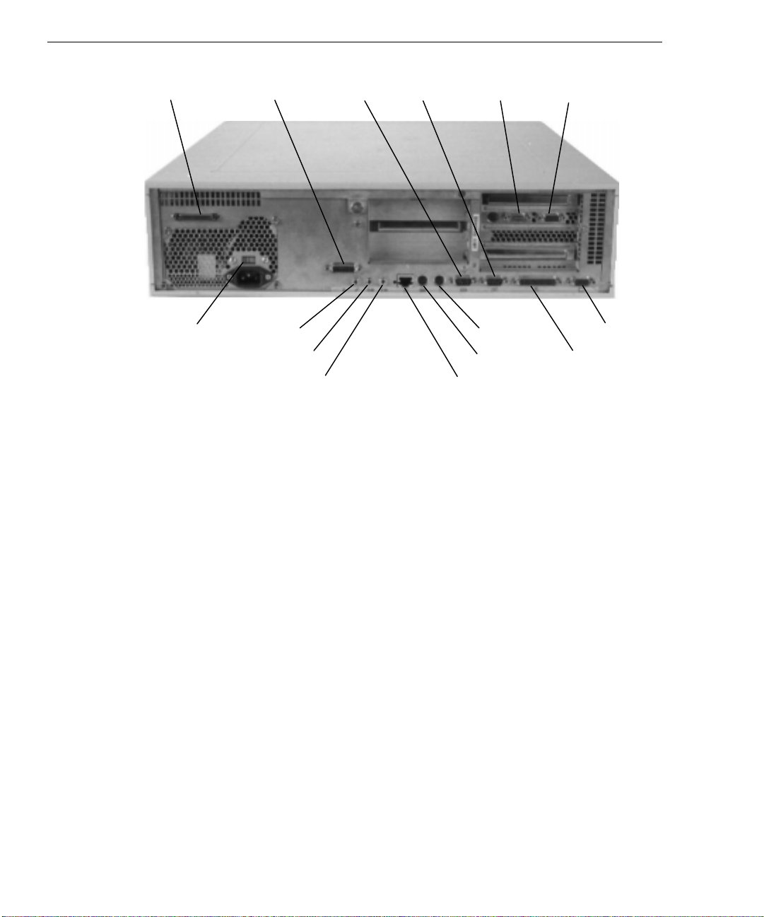
2. Connect the cables for peripheral devices to the base unit and to the peripheral devices, as
necessary. Refer to the following figure. Additional information on connecting external
SCSI devices is provided later in this chapter.
Page 16
4
SCSI Game/MIDI
AC Voltage
Switch
Microphone
Line In
Line Out
CAUTION If you are using cables not supplied by Intergraph, you must use shielded cables to prevent
excessive electromagnetic interference (EMI). Intergraph cables are designed to reduce the
amount of EMI produced by the system.
NOTE All cable ports on the base unit and on other Intergraph equipment are keyed or molded to
ensure proper cable attachment. If a cable is not attaching easily, ensure that you are
aligning the cable connector correctly with the port.
NOTE When connecting the multimedia keyboard to the base unit, the cable labeled Mic connects to
the Microphone jack, and the cable labeled Audio connects to the Line Out jack.
NOTE The ports on the back on the base unit are labeled using PC 97 compliant icons.
COM1 COM2
Video Out
Mouse
Keyboard
10/100Base-T Ethernet
VGA In
VGA Out
Parallel
Page 17
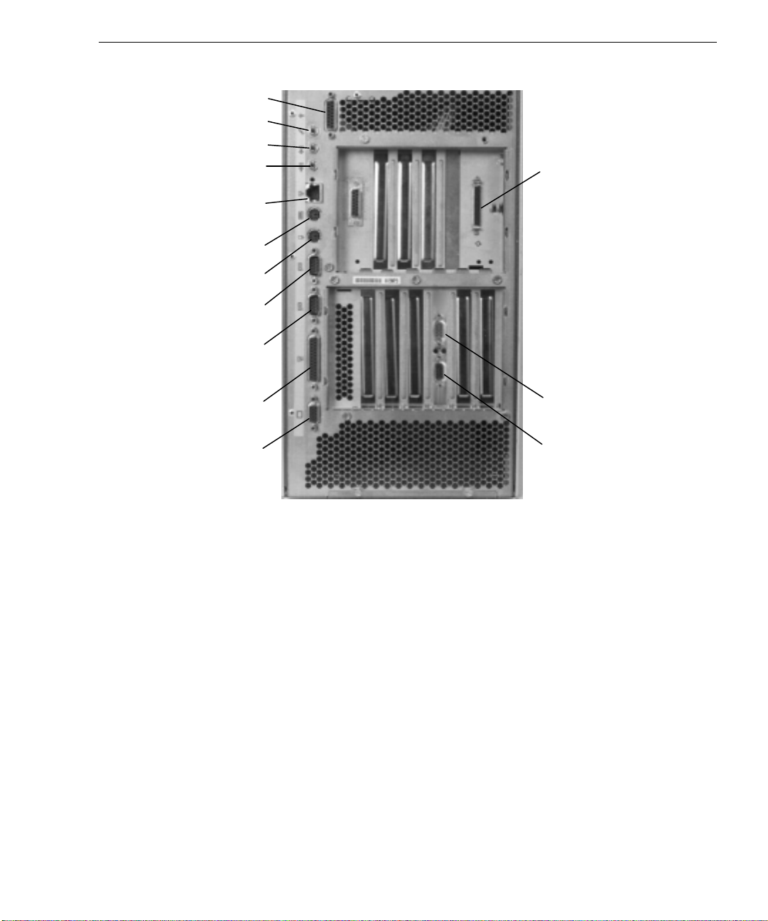
Game/MIDI
Microphone
Line In
Line Out
10/100Base-T
Ethernet
Keyboard
Mouse
COM1
COM2
5
SCSI
Parallel
VGA Out
Video Out
VGA In
3. For a desktop system, set the AC voltage switch to the proper line voltage for your
location. If you do not know the proper line voltage for your location, contact your local
power utility.
For a deskside system, the proper line voltage is detected and set automatically by the
power supply.
WARNING Ensure the power switch on the front of the base unit is disengaged (in the out
position). If the power switch is engaged, power will be applied to the system when the
base unit power cord is plugged into the AC outlet, possibly causing equipment
damage.
4. Connect the power cords for the monitor and base unit to an uninterruptible power supply
(UPS) or to a grounded three-prong AC wall outlet. Then connect the power cords to the
base unit and to the monitor.
5. Connect the monitor as described in “Connecting the Monitor” later in this chapter.
6. If setting up a system with an internal RAID disk array, install the RAID disk drives as
described in “Installing a RAID Disk Drive” later in this chapter.
Page 18
6
Connecting the Monitor
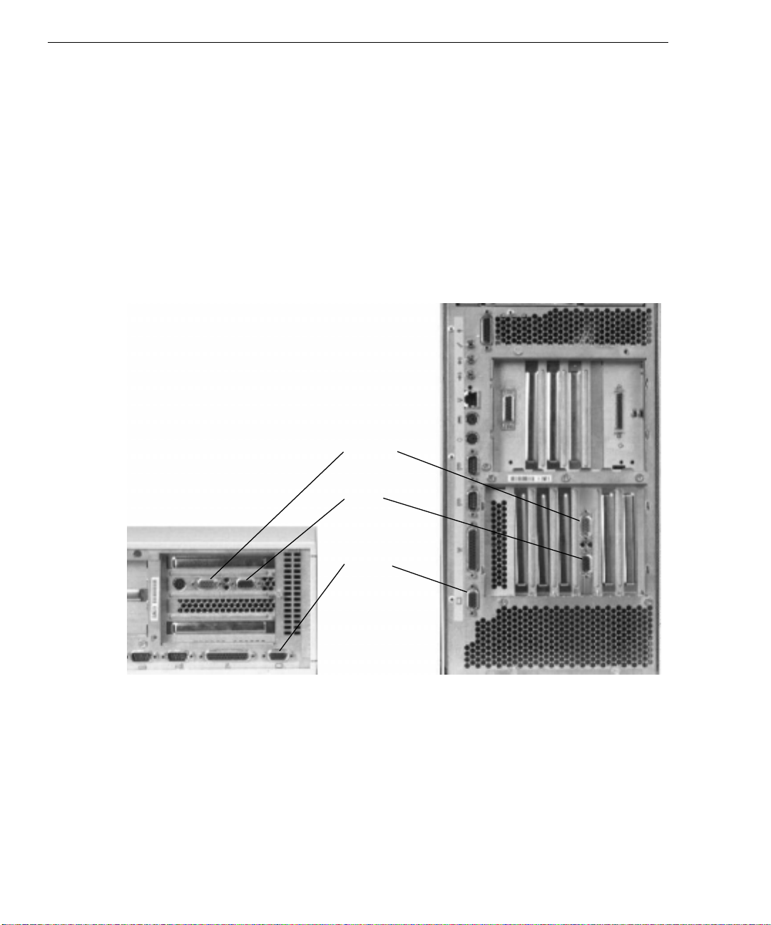
For systems using a RealiZm Z10 video display adapter:
Connect a video loopback cable to the VGA Out port adjacent to the parallel port, and to the
VGA In port on the RealiZm video display adapter. Refer to the following figure.
For systems using any video display adapter:
Connect the video cable to the monitor and to the Video Out port on the video display adapter
in the appropriate PCI slot. Refer to the following figure.
Video Out
VGA In
VGA Out
CAUTION Unless you use an on-board G95 video display adapter, do not connect the video cable for the
monitor to either of the VGA ports. If you do, the system will boot up to the blue screen and
stop, or video will not display at all.
If you use an on-board G95 video display adapter, connect the video cable to the monitor and
to the on-board VGA Out port.
For information on connecting the system to dual monitors, or for more detailed information
on the system’s video display adapter, refer to the documentation delivered with the adapter.
Page 19
Installing RAID Disk Drives
If setting up a system with an internal Redundant Array of Inexpensive Disks (RAID), you
must install the RAID disk drives before starting the system.
To install RAID disk drives:
1. Remove the RAID disk drives from the carton labeled “This box contains hard disks
loaded with operating system software.” These are the boot drives (containing the
operating system), and they are labeled with a drive ID number.
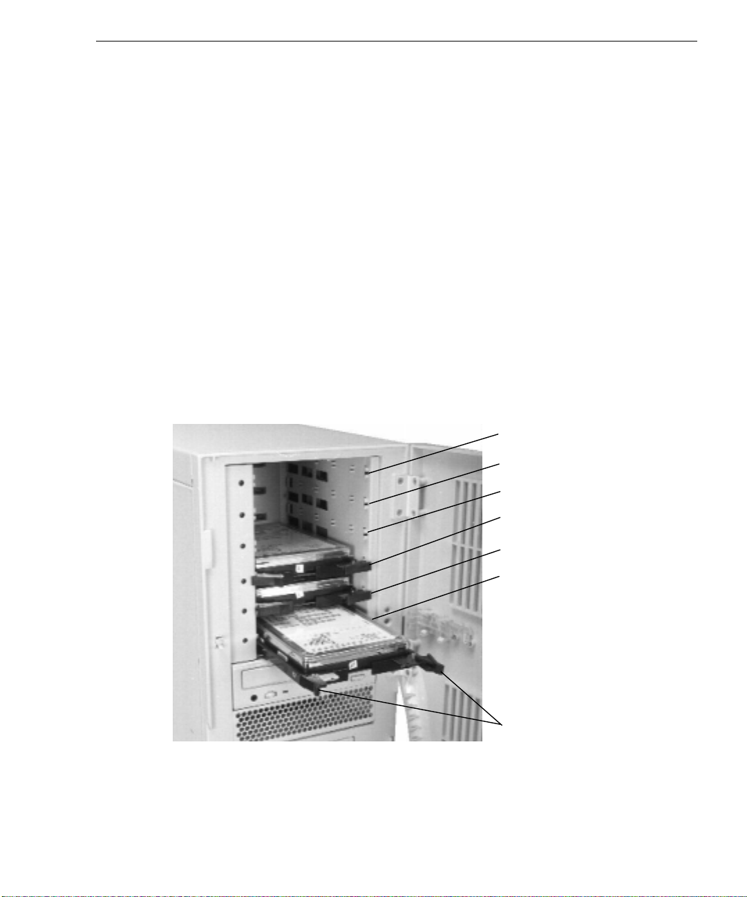
2. Install the boot drives into the internal RAID slots as shown in the following figure.
For each RAID disk drive, extend the latching clips on the drive and align the rails on the
side of the drive with the guides inside the slot. Push the drive between the latching clips
until it slides all the way into the slot and firmly engages the connector. Close the
latching clips to lock the drive in the slot.
3. RAID disk drives without labels are unformatted. You can install them in any order after
installing the boot drives. Label them as follows: drive ID 4 in slot 4, drive ID 5 in slot
5, drive ID 6 in slot 6.
7
Slot 6 (Drive ID 6 if present)
Slot 5 (Drive ID 5 if present)
Slot 4 (Drive ID 4 if present)
Slot 3 (Drive ID 2)
Slot 2 (Drive ID 1)
Slot 1 (Drive ID 0)
Latching
Clips
NOTE Do not use drive ID 3 for a RAID disk drive. Intergraph reserves SCSI ID 3 for the entire RAID
disk array.
For information on connecting to an external RAID disk array, or for more information on
RAID hardware, refer to the InterRAID documentation delivered with the system.
Page 20

8
Installing an External SCSI Device
To install an external SCSI device:
1. Set the device’s SCSI ID to an unused number and enable or disable the device’s SCSI
termination according to the vendor’s instructions.
2. Connect one end of the SCSI cable to the SCSI port on the back of the base unit. If other
external SCSI devices are installed, connect the SCSI cable to the available SCSI port on
the last device on the SCSI cable chain.
CAUTION Connecting a non-compliant SCSI-1 device to your system may cause your system to stop
working, or lead to other unpredictable results. For more information, see Chapter 3,
“Configuring the System.”
3. Connect the device to the other end of the SCSI cable.
If necessary, install the device drivers and configure the device according to the vendor’s
instructions.
Starting and Shutting Down the System
WARNING If the AC voltage switch on the back of the desktop base unit is not set to the proper
line voltage for your location, serious equipment damage may result when you turn on
power to the system.
NOTE For information on starting a system running the Solaris 2.5 for x86 operating system, refer to
Intergraph’s
The system uses a push-button power switch on the front of the base unit. To turn on system
power, push the power switch to the in position. The following figures show the front of the
base unit.
Software Configuration for Solaris 2.5 for x86
.
Page 21
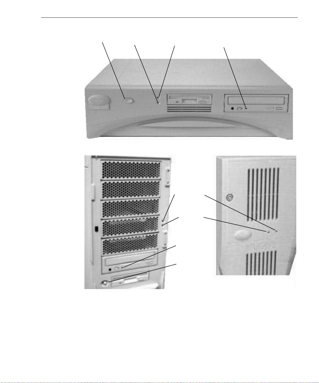
9
Power Disk
Switch Activity
LED
Power CD-ROM
On LED LED
Disk Activity
LED
Power O n
LED
CD-ROM
Drive LED
Power
Switch
Page 22

10
To start the system:
1. Turn on power to the base unit and to the monitor. The following events occur:
−
The power on LED lights.
−
The CD-ROM drive LED blinks.
−
The BIOS boot screen displays the American Megatrends logo.
−
A boot screen or Setup screen displays.
2. On a system running Windows NT Workstation, select Windows NT Workstation at the
boot screen. The operating system starts and displays a logon dialog.
If you are starting the system for the first time, the system boots to a Setup screen. Refer to
Chapter 2, “Setting Up the Software,” to set up the operating system software.
To log on to Windows NT Workstation:
1. If the logon dialog does not display, press
CTRL+ALT+DELETE to display it.
2. Type a username and password into the appropriate boxes.
3. If appropriate, type a domain name.
4. Select OK or press
ENTER.
To logoff, restart, or shut down the operating system:
1. Select Shut Down from the Start menu.
2. Perform one of the following steps, as appropriate:
- To log off from the operating system, select the logoff option, and then select OK.
- To restart the system, select the restart option, and then select OK.
- To shut down the system, select the shutdown option, and then select OK.
After shutting down the operating system, press the power switches on the base unit and the
monitor to turn off power to the system.
For more information on starting and stopping the operating system, refer to the operating
system documentation and Help.
Page 23
System Precautions
Observe the following precautions when using the system.
u
When restarting the system, use the operating system controls instead of turning the
power switch off and on. Use the power switch only when instructed, or as the last
alternative for restarting the system.
u
Never turn off power to the base unit when the disk access LED is on.
u
After turning off power to the base unit, wait at least 30 seconds before turning the power
on again to ensure that the disk drives have stopped and the system to have power-cycled
properly.
u
Run virus scan software periodically to ensure that your system’s files and programs are
not corrupted.
u
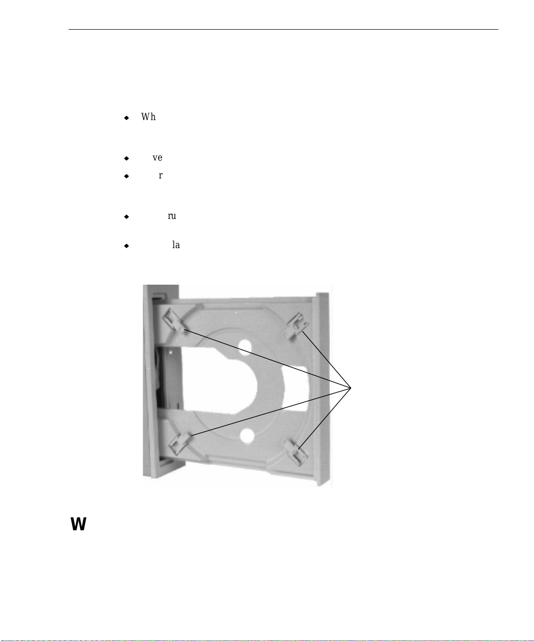
If you placed a desktop system in a vertical orientation, press the eject/load button to
open the CD-ROM drive tray. Extend at least three of the media tabs so that when you
insert a compact disc, it will not fall out. Refer to the following figure.
11
What Now?
Refer to Chapter 2, “Setting Up the Software,” for instructions on setting up the operating
system and associated system software.
Media Tabs
Page 24

12
Page 25

2 Setting Up the Software
Follow the instructions in this chapter to set up the system software for your Intergraph
TD-x10, TDZ-x1x, or TDZ-612 RAX workstation.
NOTE For instructions on setting up the system software if the system is running Solaris 2.5 for x86,
refer to Intergraph’s
Preparing for Setup .......................................................................................................... 14
Going Through Setup....................................................................................................... 16
Using the Welcome Dialog .............................................................................................. 17
InterSite Watchdog ............................................................................................ 17
InterSite Hardware Monitor............................................................................... 18
Changing InterSite Hardware Monitor Settings................................................. 18
DMI Console...................................................................................................... 19
Reviewing the System Introduction.................................................................... 20
Creating Backup Diskettes................................................................................. 21
Creating an Emergency Repair Disk or a Startup Diskette ................................ 22
Finding Customer Support................................................................................. 22
What Now? ...................................................................................................................... 22
Software Configuration for Solaris 2.5 for x86
.
13
Page 26

14
Preparing for Setup
The system shipped with the operating system and associated system software installed on the
system’s hard disk. Intergraph installed the following system software:
u
Windows NT network software (TCP/IP and NetBEUI).
u
Windows NT 4 Service Pack 3 software
u
Driver software for the on-board SCSI adapter.
u
Driver software for the on-board networking adapter.
u
Driver software for the installed video display adapter.
u
Driver software for the on-board sound processor.
u
Driver and utility software for the installed RAID controller (on a TDZ-610 system with
an internal RAID disk array).
u
Quick-Fix Engineering (QFE) update software -- fixes for operating system problems or
limitations on your Intergraph hardware or software (if needed).
u
The default File Allocation Table (FAT) file system.
The first time you start the system, it boots to a Setup screen or a logon dialog for the
operating system. If your system boots to a Setup screen, you follow the Setup process to
prepare the operating system for use.
Before you go through Setup, have the following documentation available:
u
Microsoft’s Start Here.
u
Documentation for the video display adapter delivered with the system.
Obtain and record the following information:
u
Your name, and the name of your
company or organization:
u
The CD Key from the Windows NT
Workstation, the CD key from the
Windows NT Workstation CD case, or
the Product Identification Number from
the Installation Guide or Start Here:
u
A username for setting up a user
account.
If the system is connected to a network, obtain and record the following networking
information from your network administrator:
Page 27

u
Computer name for your system:
u
Workgroup name (if the system will be
part of a workgroup):
u
Domain name (if the system will be part
of a Windows NT domain):
If the system is connected to a network that uses the Transmission Control Protocol/Internet
Protocol (TCP/IP), obtain and record the following TCP/IP networking information from your
network administrator:
u
Internet Protocol (IP) address for your
system:
u
IP subnet mask for your system:
u
IP domain name for your network:
u
IP address for your network’s default
gateway:
15
u
IP addresses for your network’s
Domain Name System (DNS) servers,
if any:
u
IP addresses for your network’s
Windows Internet Name Service
(WINS) servers, if any:
Have several blank, formatted diskettes available to create backup diskettes containing system
software.
The Windows NT delivery media contain software and drivers for both Reduced Instruction
Set Computing (RISC)- and Intel-based systems. When installing Windows NT distribution
files, make sure to install them from the \I386 directory (the Intel software directory) on the
delivery media. For example, if you are installing a device driver from the Windows NT
CD-ROM, key in the following when asked for the path to the file, where drive is the drive
letter for the CD-ROM drive:
drive:\i386
Page 28

16
Going Through Setup
The first time you start the system, it boots to a Microsoft End User License Agreement
(EULA) screen for the operating system. After reviewing and agreeing to the terms of the
agreement, follow the instructions provided on-screen to continue Setup. Take the default
settings provided by Setup, except as noted in the following text. You can set up a user
account and join a workgroup or domain after you configure the video display, the sound
processor, and networking.
u
Allow Setup to configure the network only if you have an installed network adapter, and
the system is connected to the network.
u
When prompted to create an Emergency Repair Disk, do so.
u
If you do not set up a user account during Setup, press ENTER or select OK at the logon
dialog to log on to the operating system.
u
The system’s hard disk drive contains Windows NT Setup files in the C:\i386 directory.
When installing network or video display adapter drivers, you can refer to the i
directory when prompted for the location of Windows NT Setup files. If you delete the
i
386 directory from the system’s hard disk, you must have access to a Windows NT
CD-ROM to use Windows NT Setup files.
386
For more information on Setup, and on using the interface features of the operating system,
refer to the operating system documentation and Help.
Page 29

Using the Welcome Dialog
An Intergraph Welcome icon displays on the Desktop after Setup is complete. To display the
Welcome dialog, double-click the Welcome icon, or select Programs/InterSite/Welcome from
the operating system Start menu.
17
InterSite Watchdog
InterSite Watchdog is a system monitoring product with remote monitoring capabilities. You
can install Watchdog on a system running the Windows NT 4.0 operating system, and use it to
monitor workstations and servers also running Windows NT 4.0.
When you add a system to Watchdog’s monitored systems list, Watchdog checks the system’s
Windows NT Event Log at regular intervals (called polling intervals). Watchdog looks for
error messages, warnings, and informational messages from the Intel Server Monitor,
EccMem driver, or Hardware Monitor driver in the application and system event logs. If
Watchdog finds any of these items in the event logs, it does the following:
u
Displays system, message, and other information in the event list area on the Watchdog
window on your system.
Page 30

18
u
If configured to do so, performs an action based on the time stamp of the event and the
level of the event.
If the system cannot be reached, Watchdog reports this fact to the event list in the Watchdog
window on your system.
Watchdog can be configured to take certain actions depending on the time and the type of
event it detects in the event log. For example, you can configure Watchdog to play a .WAV
file if it detects an informational error, and to send you mail if it cannot monitor the system.
Watchdog’s actions can also be customized based on the time of the event. For example, you
can configure Watchdog to play a sound file if it detects warning messages during normal
business hours, and to execute a batch file if it finds the warning message after hours.
NOTE Watchdog requires a minimum screen resolution of 800 pixels by 600 pixels.
NOTE Watchdog must be run in a Windows NT domain environment. The login from which
Watchdog is run must be a domain login that has Administrator privileges on the systems you
want to monitor.
InterSite Hardware Monitor
InterSite Hardware Monitor checks instrumentation data. The data is measured by various
hardware sensors. Event information is reported to the Windows NT Event Log. Hardware
Monitor gives the user a convenient, easy-to-use interface to graphically display the
information. For example, temperatures inside the system chassis display on color-coded
temperature scales. The user can tell at a glance if the internal temperatures are outside the
optimal operating range, and at what rate they are rising or falling.
InterSite Hardware Monitor displays data such as general system information, system
temperatures, CPU voltages, power plane voltages, and memory configuration information if
relevant to the system you are using. Users can configure the interval between status checks,
the types of events that are logged, and temperature thresholds. Hardware Monitor writes to
the Windows NT Event Log when instrumentation data is above the user-defined thresholds.
Changing InterSite Hardware Monitor Settings
Any user on the system can run the InterSite Hardware Monitor program. However, if you
want to change any of the settings in the Hardware Monitor program, you must do so from an
account that has Administrator privileges.
Refer to the
Monitor Help, for more information on changing Hardware Monitor settings. You can find
Hardware Monitor on the Start menu, under Programs/InterSite.
README.TXT file delivered with the Hardware Monitor program, and to Hardware
Page 31

DMI Console
The Desktop Management Interface (DMI) is a technology standard that enables the effective
management of personal computers (PCs). The InterSite DMI Console is software that
provides easy-to-use access to the information embedded in a DMI-enabled PC.
The following list shows the advantages of using DMI to manage PCs:
u
u
u
u
u
u
u
The InterSite DMI Console gives easy access to the PC’s status and configuration information
through a window containing a graphical information tree view pane, a service provider
component information pane, and a message pane.
19
Constantly updates information to reflect changes in the PC’s status.
Meets a growing need to support a large number of users in a multi-vendor environment.
Makes management of PCs and PC components independent of any particular vendor,
operating system, or management protocol.
Reduces labor costs for network managers.
Facilitates easy inventory, asset management, preventative maintenance, software
updates, and automatic software inventory.
Improves data and network security.
Increases PC uptime.
Page 32

20
Reviewing the
Click the button on the System Introduction tab to display the System Introduction. This
document is an online introduction to your new system in Windows Help 4.0 format, covering
such subjects as system features, system controls and connections, and Intergraph customer
support. Review the information in the System Introduction to become more familiar with
your system.
System Introduction
NOTE You can also view the
C:\WIN32APP\SYSINTRO directory on the system disk. You may want to link the SYSINTRO.HLP file
to an icon, a shortcut, or a system menu to make it easier to display.
System Introduction
by opening the SYSINTRO.HLP file in the
Page 33

Creating Backup Diskettes
Backup diskettes for drivers and other system software products are not delivered with the
system. Click the Version Manager button on the Version Manager tab to create system
software backup diskettes with the InterSite Version Manager.
21
Version Manager lets you create backup diskettes containing drivers and other system
software products that were installed on the system before shipment. You may need these
backup diskettes later -- for example, if you have to re-install a device driver or the operating
system.
WARNING You must create system software backup diskettes after you set up the system
hardware and complete the operating system Setup program. If you do not do this, you
may not be able to re-install critical system software or the operating system if needed.
NOTE You may not have to create backup diskettes for system software. If Version Manager does
not list drivers or other system software products, they are available on the operating system
software CD-ROM or on backup diskettes delivered with expansion boards.
Page 34

22
If the system requires Quick-Fix Engineering (QFE) update software, it is included in the
system software available for backup diskette creation. QFE update software contains fixes
for operating system problems or limitations, and is only shipped with the system if it is
needed. If QFE update software is shipped with the system, you should create a QFE backup
diskette for use if you have to re-install the operating system.
Refer to Version Manager Help for information on creating Intergraph system software and
other diskettes. Check the Intergraph site on the World Wide Web and vendor bulletin boards
for new and updated drivers.
Creating an Emergency Repair Disk
If you did not create an Emergency Repair Disk during Setup, click the Repair Disk button on
the Repair Disk tab to create the appropriate diskette. The files on these diskettes can restore
the original contents of a damaged Registry (that is, at the time the operating system was
installed), along with the standard operating system drivers. You should also update an
Emergency Repair Disk after you finish configuring the system.
Refer to the operating system documentation and Help for information on creating an
Emergency Repair Disk.
Finding Customer Support
The Support tab contains information useful in contacting Customer Support. This
information is repeated in the Preface, earlier in this Guide.
What Now?
Refer to Chapter 3, “Configuring the System,” to configure the system for use.
Refer to the online System Introduction for information on system features and controls.
Page 35

3 Configuring the System
Follow the instructions in this chapter to configure your Intergraph TD-x10, TDZ-x1x, or
TDZ-612 RAX system for use.
NOTE For instructions on configuring the system if it is running Solaris 2.5 for x86, refer to
Intergraph’s
Configuring the Video Display......................................................................................... 24
Configuring the RealiZm and Intense 3D Pro Video Display Drivers ............................. 24
Configuring the G95 Video Display Driver ..................................................................... 24
Configuring Support for Heidi Graphics.......................................................................... 27
Correcting Video Display Problems................................................................................. 28
Configuring Networking...................................................................................................29
Configuring the Sound Driver.......................................................................................... 29
Configuring Free Disk Space ........................................................................................... 29
Configuring External SCSI Peripherals............................................................................ 30
Configuring and Using the RAID Disk Arrays................................................................. 31
Ensuring PC Card Support and Operation........................................................................ 31
Updating the Operating System........................................................................................ 32
Software Configuration for Solaris 2.5 for x86
Changing the Monitor Refresh Rate................................................................... 25
Changing the Dual-Screen Style........................................................................ 27
Disabling Ultra SCSI Capability........................................................................ 30
Using the SCSISelect Utility.............................................................................. 31
.
23
Page 36

24
Configuring the Video Display
When you start your system for the first time, it uses the installed graphics accelerator running
at 1024 x 768 screen resolution to run the video display. For the system to use the installed
video display adapter at other display resolutions, you must configure the video display driver
for the installed video display adapter. You can do this during first-time setup.
If your system uses a RealiZm or Intense 3D Pro video display adapter, refer to the video
display adapter documentation delivered with the system for instructions on selecting a dualscreen style. If your system uses a G95 video display adapter, refer to the instructions in
“Changing the Dual-Screen Style” later in this chapter.
Configuring the RealiZm and Intense 3D Pro Video Display Drivers
Open Display in the Control Panel to configure the video display. Use the Settings tab in the
Display Properties dialog to change the color palette, desktop size, font size, refresh rate, and
display type. Use the Hardware Settings tab to change the monitor type, screen display, and
preferences.
For detailed information on configuring the RealiZm or Intense 3D Pro video display driver
on your system, refer to the video display adapter documentation and Help delivered with the
system, and to the
README.TXT files delivered with the video display drivers.
Configuring the G95 Video Display Driver
Use the Display application in the Control Panel to change the configuration of the G95 video
display driver.
To change the G95 video display driver configuration:
1. Open Display in the Control Panel.
2. Change the settings as follows:
− Use Refresh Frequency to select the refresh rate for the video display.
− Use the MGA Monitor utility to completely characterize your monitor at all of the
resolutions it is equipped to display, to ensure the best possible performance.
− Use Font Size to select a font size for the display type. The options supported are
usually Small Fonts and Large Fonts.
Page 37

−
Use Color Palette to select the number of colors for the display.
−
Use Desktop Area to change the resolution for the display. Larger resolutions cause
items to look smaller on the screen.
NOTE If your system has dual G95 displays, you are offered desktop resolutions that are horizontally
or vertically doubled in size, corresponding to the side-by-side or vertical logical stacking of
the video monitor display areas. For example, a pair of monitors side-by-side each running at
1600 x 1200 display resolution would be represented in the Display Settings Dialog as an
available 3200 x 1200 display resolution. Refer to “About the System’s Video Display” in this
chapter for more information on dual-screen displays.
NOTE Changing one display setting may cause others to shift automatically. For example, if you
select 16.7 million colors in the Color Palette, the Desktop Area may automatically change to
a supported resolution for that color depth.
NOTE You can select List All Modes to display all of the resolutions supported by the display driver.
Select the display mode you want to use from the Valid Modes dialog.
3. Select Test to see how your selected settings work with your monitor.
4. When the selected settings are satisfactory, select OK to close the Display Settings dialog;
then close Control Panel.
5. Restart the system.
6. After restarting the system, if windows are displayed partially off the screen, use the
mouse to double-click the title bar and move the windows back onto the screen. You can
also bring up the task list (by double clicking on the Windows NT background) and click
the Cascade button to cascade the windows.
25
Changing the Monitor Refresh Rate
By default, the G95 display driver assumes your system has a 60 Hz monitor. If your monitor
is capable of higher refresh rates, you should run the MGA Monitor application to select a
different monitor with a higher refresh rate.
To change the monitor refresh rate:
1. Open MGA Monitor in the Control Panel. The MGA Monitor Selection dialog displays.
Page 38

26
2. Select the appropriate monitor from the Monitor List. If your system’s monitor is not
listed, select one with a maximum refresh rate matching the refresh rate your system uses.
An
MGA.INF file will be created in the SystemRoot/SYSTEM32 directory.
NOTE In a multiple G95 configuration, the MGA.INF setting affects all monitors. Intergraph
recommends that you select a monitor that is compatible with the least-capable monitor used
by your system.
To test the new monitor selection:
1. Open Display in the Control Panel.
2. Select the resolution and pixel depth you want to test.
3. Select Test. If the display is satisfactory, go to step 6. If not, continue.
4. If your monitor does not display a stable test screen, the parameters set by the
MGA.INF
file are not suitable for your monitor. Select Cancel to close Display.
5. Run MGA Monitor again to select a different monitor.
6. Repeat steps 1 through 3 to test the video display with the new monitor selection. When
the display is satisfactory, close Display.
7. Restart the system.
No resolution higher than the limit imposed by a monitor selection appears in the Display
mode list. Deleting the
MGA.INF file removes all monitor limits to the resolution, although the
refresh rate defaults to 60 Hz.
Page 39

Changing the Dual-Screen Style
To change G95 dual-screen style, you must edit the Windows NT Registry.
WARNING Do not change values in the Registry other than as directed. If you introduce incorrect
values into the Registry, you may cause serious operating system problems, and you
may have to re-install Windows NT. If you change values in the Registry that make your
system unusable, you may be able to restart the system and use the Last Known Good
Configuration option to undo the damage. Refer to the operating system
documentation for more information on the Last Known Good Configuration option.
To change the dual-screen style:
27
1. Start the Registry Editor (
REGEDT32.EXE) to open the Registry.
2. Open the following subkey in the Registry:
HKEY_LOCAL_MACHINE\SYSTEM\CurrentControlSet\Services\mgax64\
Device0
3. In the right-hand pane of the Registry Editor window, select User.CenterDialogs.
4. From the Edit menu, select DWORD.
5. To enable Primary Top/Left style, type 0 into the Data box. To enable Full Canvas style,
type 1 into the Data box.
6. Select OK.
7. Exit from the Registry Editor and restart the system.
Configuring Support for Heidi Graphics
The RealiZm graphics accelerators on TD-x10, TDZ-x1x, and TDZ-612 RAX systems support
Heidi graphics for 3D Studio MAX. Intergraph’s Heidi Device Driver, which depends on the
Intergraph Display Driver for RealiZm graphics accelerators, provides the support.
The Heidi Device Driver is installed during installation of the Intergraph Display Driver for
RealiZm graphics. After you install 3D Studio MAX on your system, copy the Heidi Device
Driver file
3
DSMAX\DRIVER directory.
GLZIHDD.HDI from the Windows NT Workstation SYSTEM32 directory to the
NOTE Use the version of the Heidi driver that matches the version of the display driver.
Refer to the README.TXT file delivered with the Heidi Device Driver for detailed instructions
on the driver and any associated files.
Page 40

28
Correcting Video Display Problems
If the system’s video display is black, not synchronized, or distorted after you restart the
system, you may have a video configuration problem. Do not press
on to the Windows NT operating system. Instead, try to correct the problem by using the Last
Known Good option to return the system to the last know good configuration recorded by
Windows NT.
To use the Last Known Good option:
1. Power down and restart the system.
2. Press the space bar at the following prompt:
Press space bar NOW to invoke the Last Known Good Menu
3. If using the Last Known Good option fails to correct the video display problems, you can
obtain a functional video resolution by restarting the system in VGA mode.
To restart the system in VGA mode:
1. Power down and restart the system.
2. At the boot screen, select the VGA mode option appropriate for your system.
CTRL+ALT+DELETE to log
After logging on to Windows NT in VGA mode, check for the following common
configuration problems and solutions.
u
A multi-sync monitor is connected to the system, but a multi-sync monitor type is not
selected, and the display driver cannot determine this by querying the monitor. Select an
appropriate multi-sync monitor type.
u
A selected resolution, depth, or refresh rate is not supported by the multi-sync monitor.
Try using different video display settings.
u
The Dual Screen option is selected, but only one video board is detected. Clear the Dual
Screen option.
u
A multi-sync monitor is selected, but a monitor with different video timings (such as an
Intergraph InterVue monitor) is connected to the system. Select the appropriate monitor
type as described previously.
u
The monitor selection is inappropriate for the multi-sync monitor attached to the system.
Restart the system in VGA mode, then select a new monitor as described previously.
u
A graphics resolution and color depth has been selected that exceeds installed display
memory. Restart the system in VGA mode, then open Display in the Control Panel to reinstall and configure the display driver as described in the video display adapter
documentation delivered with the system.
Page 41

Restart the system and select the non-VGA version of the appropriate operating system to use
the reconfigured video display driver. If problems persist, contact the Intergraph Customer
Response Center for help.
Configuring Networking
The system is equipped with an on-board Ethernet network adapter. Before you configure
networking, ensure that the system is connected to the network.
To configure Networking, open Network in the Control Panel. Follow the instructions in the
dialogs to set up the system to use a network. Be sure to set up the appropriate network
protocols, such as TCP/IP and NetBEUI, for the network to which the system is connected.
Refer to the operating system documentation and Help for detailed information on setting up
the operating system to use a network.
Configuring the Sound Driver
29
The system is equipped with an on-board sound processor whose driver was pre-configured.
If the system has a multimedia keyboard or a microphone and speakers, you can use the
operating system’s sound control programs to control them.
Refer to the operating system documentation and Help for information on using the sound
control programs.
Configuring Free Disk Space
If the system is equipped with an internal system disk drive larger than 2 GB, it was
configured at the factory with a 2 GB system partition. The remainder of the space on the
drive is left raw. Before you can gain access to and use the raw space, you must format it
using the Windows NT Disk Administrator. Refer to the operating system documentation and
Help for more information.
If the system is equipped with a RAID disk array, use the Windows NT Disk Administrator to
configure and format free space on the RAID system drive. If you have additional RAID hard
disk drives, initialize and configure them using the DAC Configuration utility. Then use Disk
Administrator to configure and format the free space on the additional RAID disk drives.
Refer to the InterRAID documentation delivered with the system for more information.
Page 42

30
Configuring External SCSI Peripherals
TDZ-612 and TDZ-612 RAX systems are equipped with a separate Ultra SCSI controller for
external SCSI devices. If you use a non-Ultra SCSI device, data transfer rates are limited to
the device’s speed.
TD-x10 and TDZ-x10 desktop systems are equipped with an Ultra SCSI controller for all
SCSI devices. If you use a non-Ultra SCSI device, data transfer rates are limited to the
device’s speed.
TD-x10 and TDZ-x10 deskside systems are equipped with a separate SCSI-2 controller for
external SCSI devices. You should use only SCSI-2 devices with the external SCSI port. If
you use an Ultra SCSI device, data transfer rates are limited to the controller’s SCSI-2 speed.
If you use a SCSI-1 device, data transfer rates are limited to the device’s speed.
CAUTION Using a non-compliant SCSI-1 device with your system may cause your system to stop
working, or lead to other unpredictable results.
You can use up to five external single-ended SCSI devices with a desktop system, and up to
seven external single-ended SCSI devices with a deskside system. The total length of the
external SCSI cables depends on the number of devices connected to the SCSI adapter.
The total length must not exceed the following:
SCSI-1 SCSI-2
1 to 4 devices 6 meters 3 meters 3 meters
5 to 8 devices 3 meters 3 meters 1.5 meters
NOTE You must count the controller as one device.
When calculating the total length of the SCSI cables connected to the SCSI adapter, use the
following estimates where appropriate:
SCSI cabling inside a desktop system 101.6 mm
SCSI cabling inside each external device 203.2 mm
NOTE The last external device on the SCSI cable chain must supply active termination. All other
external devices must have SCSI termination disabled or removed.
Ultra SCSI
Disabling Ultra SCSI Capability
To ensure proper operation of the external SCSI devices with a desktop system, you should
disable Ultra SCSI capability under the following conditions:
Page 43

u
If you exceed the total cable length for connecting SCSI devices to the system, as
specified in the documentation delivered with the system.
u
If you connect non-Ultra SCSI external devices to the system.
Use the SCSISelect utility to disable Ultra SCSI capability on the system.
NOTE When you run the SCSISelect utility, Ultra SCSI capability is disabled if you select Restore
Power-On Defaults. If you do not want to disable Ultra SCSI capability, be sure to enable it
after selecting Restore Power-On Defaults.
Using the SCSISelect Utility
The SCSISelect utility is a separate utility on the System Utilities (SYSUTIL) diskette
delivered with your TD-x10, TDZ-x1x, or TDZ-612 RAX system.
To run the SCSISelect utility:
1. Insert the SYSUTIL diskette into the system’s floppy disk drive.
2. Restart the system.
3. When the Startup Menu displays, select the SCSISelect option.
31
4. Follow the displayed instructions and online Help to use SCSISelect.
Configuring and Using the RAID Disk Arrays
If your system is equipped with an internal or external RAID disk array, refer to the
InterRAID documentation delivered with the system for information on configuring and using
the disk array.
Ensuring PC Card Support and Operation
The PC Card slot in the optional combo drive is used with devices based on standards
developed by the Personal Computer Memory Card International Association (PCMCIA).
Windows NT provides support for PC Card devices. Refer to the operating system
documentation and Help for more information on PC Card device support.
CAUTION You must shut down the system before inserting a PC Card device in the PC Card slot. When
you restart the system, Windows NT will recognize the PC Card device.
Page 44

32
If you will be using a PC Card hard disk device (ATA or AT type) with a system running
Windows NT, make sure the device drivers that control PC Card hard disk operation are set to
start correctly.
Both the Atdisk device and the Pcmcia device should be set to start as System devices.
Do this before inserting a PC Card hard disk device in the PC Card slot. If you do not,
anomalous behavior may result -- for example, the PC Card hard disk drive may not be
detected by Windows NT, or may be detected as the system drive (drive C).
To change startup type for device drivers that control PC Card hard disks:
1. Open Devices in the Windows NT Control Panel. The Devices dialog displays.
2. Highlight the device in the Device list; then select Startup. The Device dialog displays.
3. Under Startup Type, select the appropriate startup type; then select OK.
4. In the Devices dialog, select Close.
Additionally, some PC Card devices require that specific system resources be reserved for
proper operation. If so, run the System Configuration Utility (SCU) to reserve the resources;
see the System Reference for more information. Refer to the documentation supplied with
your PC Card device for information about the required system resources.
Updating the Operating System
Microsoft Service Packs contain the latest improvements and system fixes for Microsoft
operating systems. Service Packs are created by Microsoft for post-release support. You can
obtain Service Packs from Microsoft’s World Wide Web and FTP sites free of charge.
CAUTION If Intergraph provides a Service Pack through the IBBS or with a product or system, it has
been certified against Intergraph hardware as described in the announcement of its
availability. If you obtain a Service Pack from any other source, be aware that it may not be
certified against your Intergraph hardware.
Page 45

4 Configuring the BIOS
Your system’s Basic Input/Output System (BIOS) records basic system operating parameters,
such as the amount of memory, the boot sequence, and the type of video display. The
system’s operating parameters are set in the BIOS before shipment. However, you may want
to configure some aspects of system operation by changing the BIOS settings, or update the
BIOS to take advantage of enhancements provided by Intergraph.
The BIOS is stored in flash erasable-programmable memory (EPROM) on the system board,
and reads the system parameters in the system’s complementary metal-oxide semiconductor
(CMOS) random-access memory (RAM). When you power off the system, a lithium battery
provides power to CMOS RAM to retain the system’s operating parameters. Each time you
power on the system, the BIOS uses stored parameters to configure the system.
Starting AMIBIOS Setup .........................................................................................................34
Using AMIBIOS Setup ............................................................................................................35
Standard Setup...........................................................................................................35
Advanced Setup.........................................................................................................36
Chipset Setup.............................................................................................................38
Peripheral Setup.........................................................................................................41
Utility Menu...............................................................................................................43
Security Menu............................................................................................................43
Default Menu.............................................................................................................44
Reprogramming the BIOS........................................................................................................45
Changing the System Boot Sequence.......................................................................................47
33
Page 46

34
St arting AMIBIOS Setup
The AMIBIOS Setup program, which is also stored in the flash EPROM on the system board,
allows you to manually change the system’s operating parameters. The Flash Programming
Utility (FPU) allows you to reprogram the BIOS. This chapter tells how to use AMIBIOS
Setup and FPU.
The BIOS version number displays as the system starts. The message is similar to the
following:
AMIBIOS (C) 1996 American Megatrends Inc.,
(C) 1996 Intergraph Corporation (752XX)
NOTE TD-310, TDZ-310, TD-410, and TDZ-410 systems use the 752xx.ROM BIOS, and TD-610,
TDZ-610, TDZ-612, and TDZ-612 RAX systems use the 782xx.ROM BIOS, where xx is the
version number.
To start AMIBIOS Setup:
1. Restart the system. The following message displays:
Press DEL to enter Setup
2. Press
DELETE. The AMIBIOS Setup Main Menu displays.
This screen allows access to menus for configuring the BIOS to suit your own needs or
perform maintenance as needed. The following sections describe the parameters you can
access through each menu.
NOTE You can set a password to prevent unauthorized users from accessing AMIBIOS Setup. Refer
to “Security Menu” in this chapter.
While using AMIBIOS Setup, remember these tips:
u
To access Help, press ALT+H. The Keystroke/Mouse Convention list displays, which
explains how to select Setup menu items with the mouse pointer and with keys. Press any
key to close the list and return to AMIBIOS Setup.
u
To change a parameter’s value, move the pointer to a parameter and click the mouse
button. An Options menu displays allowing you to select one of the choices.
u
When you are at the main menu in AMIBIOS Setup, press ESC to exit. The Save Changes
and Exit option is highlighted, press
ENTER to exit. Any changes you made while in the
program will be saved. If you select the Continue option, then you will return to
AMIBIOS Setup.
Page 47

Using AMIBIOS Setup
The AMIBIOS Setup menu allows you to change most of the BIOS settings. This section
describes the parameters grouped in the AMIBIOS Setup menu.
Standard Setup
The Standard Setup menu allows you to set the system date and time, and define floppy disk
drive parameters.
Date/Time
Select the Date/Time icon to display the current system date and time values.
To change the system date and time:
35
1. Click on the incorrect value with the mouse pointer or press the
highlights.
2. Click on the + or - buttons to change the value, or enter the correct value from the
keyboard.
NOTE The time displays in 24-hour format.
3. Press ESC to save the new values and return to Standard Setup.
Floppy A, Floppy B
The Floppy A and Floppy B icons allow you to specify the type of floppy disk drive installed
in the system.
The floppy disk drive A parameter is preset to 1.44 MB 3.5-inch. Do not change the
parameter unless you replace floppy drive A with a different capacity disk drive.
The floppy disk drive B parameter is preset to Not Installed, unless an optional drive has been
installed before shipment. Do not change the parameter unless you install an optional floppy
disk drive.
To change the floppy drive parameters:
1. Select the Floppy A or Floppy B icon.
2. Press the up and down arrow keys or click in a box to select the correct parameter for the
floppy disk drive.
TAB key until the value
3. Press
ENTER to accept the change, or click on the close icon in the upper left corner of the
floppy disk drive configuration menu.
Page 48

36
Master Disk, Slave Disk
The Master Disk and Slave Disk icons represent parameters for Integrated Device Electronic
(IDE) drives. If installing IDE hard drives, use the Detect Master and Detect Slave utilities to
automatically detect and configure the drives. Refer to “Utility Menu” for more information.
To change the IDE drive parameters:
1. Select Master Disk or Slave Disk.
2. Select USER from the list of drive types.
3. Select each of the following parameters and enter the appropriate values. For more
information, refer to the documentation included with the device.
CYL Cylinders
HD Heads
WP Write Precompensation
LZ Landing Zone
SEC Sectors
4. When complete, press
Advanced Setup
The Advanced icon in the AMIBIOS Main Menu allows you to change details of the system’s
operation. Each parameter included in the Advanced Setup menu is described below.
System Boot Up Sequence
This parameter specifies the device sequence for system boot up. The default is C:, A:, which
means the system attempts to boot from drive C first. If unsuccessful, it attempts to boot from
drive A. By default, C: is the system hard disk drive and A: is the floppy disk drive. Change
this parameter to A:, C: to boot the system from a diskette in the floppy disk drive. Refer also
to Operating System Boot Device parameter in “Chipset Setup.”
Above 1 MB Memory Test
When enabled, this parameter invokes the Power On Self Test (POST) memory routines on
the RAM above 1 MB. If disabled, the BIOS will check only the first 1 MB of RAM.
Memory Test Tick Sound
This parameter enables or disables the ticking sound during the memory test.
ESC or click the close box at the upper left corner of the window.
Page 49

37
System Keyboard
This parameter enables or disables BIOS keyboard testing. Acceptable values are Absent and
Present. If Present (default) is selected, the BIOS tests for the keyboard when the system
boots and provides an error message if the keyboard is not present. If Absent is selected, the
BIOS does not test for the presence of a keyboard.
Typematic Rate
This parameter defines the rate at which a keystroke repeats when you press and hold down a
key. Accepted values are 15, 20, or 30 (default) characters per second.
System Boot Up Num Lock
This parameter, when set to On (default), disables the arrow keys on the numeric keypad. The
Num Lock option on the keyboard can be turned off and on while the system is operating.
Wait for ‘F1’ on Error
When set to Enabled (default), the system will display the Press <F1> to RESUME
message if an error occurs during boot up diagnostic tests. If this setting is Disabled, any nonfatal errors will not generate the statement, but the AMIBIOS will display the appropriate
error message.
Hit ‘DEL’ Message Display
When set to Enable (default), the system provides a message during boot up that the
AMIBIOS Setup program can be accessed by hitting the
DELETE key. Disabling this
parameter prevents the message from displaying.
Floppy Drive Seek at Boot
When set to Enabled, AMIBIOS performs a Seek command on floppy disk drive A before
booting the system. The default setting is Disabled.
Password Checking
This parameter prevents unauthorized system boot up or use of AMIBIOS Setup. Setup (the
default) enables the system to prompt for a password before allowing you to enter AMIBIOS
Setup. If you select Always, the password prompt appears each time the system is powered
on. The Change Password value enables you to press
ENTER at the password prompt to
disable this parameter.
Page 50

38
ISA Video Shadow C000, 32K
ROM shadowing is a procedure in which BIOS code is copied from ROM to RAM when the
system boots. When set to Enabled (the default) the BIOS then executes from RAM,
providing faster access time and improving system performance.
ISA Adaptor Shadow XXXX, 16K
For ISA boards that contain a BIOS on ROM, Enabled allows you to tell the ISA board BIOS
to be copied from the ISA board ROM to system board RAM. An ISA board BIOS executes
faster from system board RAM than from the ISA board ROM. All of the ISA Adapter ROM
parameters are set to Disabled by default.
NMI on System Error
This parameter halts the system when a catastrophic error is detected. This prevents the error
from corrupting your data. The default is Enabled.
NOTE The following Advanced Setup parameters are useful only if an IDE disk drive is connected to
the system.
IDE Block Mode
This parameter enables transfer of data in blocks (multi-sector) for both read and write
operations. This option is set to Disabled by default.
NOTE To use the following Advanced Setup parameters, the hard disk drive must support LBA
mode, and it must be formatted with LBA mode enabled.
IDE Master LBA Mode
This parameter enables Logical Block Addressing (LBA) mode for master hard disks
connected to the IDE controller. LBA mode translates the physical parameters of the hard
disk to logical parameters, permitting the use of disk space beyond 528 MB.
IDE Slave LBA Mode
This parameter enables LBA mode for slave hard disks connected to the IDE controller. LBA
mode translates the physical parameters of the hard disk to logical parameters, permitting the
use of disk space beyond 528 MB.
Chipset Setup
The Chipset Setup menu contains the parameters that affect the functionality of some
hardware components.
Page 51

Sound Controller
This parameter enables or disables the sound processor circuitry on the system board. The
default is Enabled.
PCI VGA Palette Snooping
This parameter allows palette data from an installed PCI graphics board to be shared with an
installed ISA graphics board. Since the graphics delivered with the system are PCI-based, this
option is set to Disabled by default.
PCI Video Frame Buffer
The PCI Video Frame Buffer parameter allows you to implement the read prefetch support in
the linear buffer of the system graphics hardware. System performance increases when set to
Enabled (the default).
NOTE If you install a graphics card that does not support read prefetch, you must disable the PCI
Video Frame Buffer for proper display.
PCI Frame Buffer USWC Mode
39
When enabled (default), this parameter removes from the buffer polygon data that otherwise
would be obscured by other polygons. This reduction in the amount of data written to the
display improves video performance by reducing the time required to update the display. The
BIOS disables this parameter if it detects an incompatible video card.
On-Board SCSI Controller (Desktop)
External SCSI Controller (Deskside)
When set to Enabled (default), this parameter activates the on-board, PCI-based SCSI
controller. The SCSI controller can be disabled by changing the value to Disabled. This
parameter can be modified only by the Supervisor.
Internal SCSI Controller (Deskside)
When set to Enabled (default), this parameter activates the PCI-based SCSI controller
mounted on the riser card. The SCSI controller can be disabled by changing the value to
Disabled. This parameter can be modified only by the Supervisor.
Operating System Boot Device
This parameter specifies which controller the BIOS will attempt to boot from first. The device
that you specify to be the boot device is assigned to drive C. By default, drive C is the system
hard disk drive. Refer also to the System Boot Up Sequence parameter in “Advanced Setup.”
Page 52

40
Boot to PnP Operating System
When this parameter is set to No (the default), the BIOS initializes all devices during boot up.
When set to Yes, the BIOS only performs the amount of initialization required to load the
operating system. Any other device initialization must then be performed by the operating
system.
PCI IDE Card Present in
Some PCI option boards do not comply with the PCI specification. Use this parameter to
indicate the slot number of a noncompliant PCI IDE option board. Some PCI IDE boards are
fully compliant, in which case this option is not needed. The settings are Absent, Slot 1, or
Slot 2. PCI IDE boards are never supported in slots 3 through 6. The default setting is
Absent.
PCI IDE IRQ14 Connected to
When the PCI IDE Card Present In option is used to select a slot number, this parameter is
active. The options are Edge and Level. When activated, the default is Level.
PCI IDE IRQ15 Connected to
When the PCI IDE Card Present In option is used to select a slot number, this parameter is
active. The options are Edge and Level. When activated, the default is Level.
Installed Memory Speed
Set this parameter to match the speed of the memory SIMMs installed in your system. The
options are 60 (default) and 70 ns.
Use ESCD for PCI IRQ Assignment
If this parameter is set to Yes, when the system boots, it reads ESCD data to determine how to
assign IRQs to system devices and option cards. You can use PnP operating systems to
manipulate this ESCD data to assign specific IRQs to specific system devices and option cards
on subsequent system boots. When the parameter is set to No (default), you can use the BIOS
to assign IRQs to PCI devices regardless of ESCD instructions.
PCI Slot x IRQ Priority
Use these parameters to assign specific IRQs to specific PCI cards when ESCD data is not
being used.
Page 53

41
DMA Channel x Usage
These parameters specify whether a given DMA channel is to be reserved for an ISA card, or
is free to be assigned to another device by the PnP BIOS. The options are PnP (default) and
ISA.
IRQ x Usage
These parameters specify whether a given IRQ is to be reserved for an ISA card, or is free to
be assigned to another device by the PnP BIOS. The options are PCI/PnP (default) and ISA.
ISA Reserved Memory Size
Use this parameter in conjunction with the ISA Reserved Memory Address parameter to
allocate a fixed amount of memory for ISA cards that require a specific amount of memory
and a set memory location. The memory size you select limits the memory addresses available
to assign to ISA cards.
ISA Reserved Memory Address
Use this parameter in conjunction with the ISA Reserved Memory Size parameter to allocate a
fixed amount of memory for ISA cards that require a specific amount of memory and a set
memory location. The memory addresses available depend on the memory size you select.
Peripheral Setup
The Peripheral Setup menu has parameters that affect option boards, serial ports, and parallel
port functionality.
Programming Mode
This parameter detects all installed option boards and configures the on-board components
accordingly. When set to Auto (the default), the system BIOS automatically detects the
installed option boards during boot up. When set to Manual, the next four parameters, plus
Parallel Port IRQ, activate.
OnBoard FDC
When set to Enabled (the default), this parameter enables the system floppy disk drive I/O
controller on the system board. If you install floppy controller cards, then this parameter must
be set to Disabled.
Page 54

42
Serial Port1
This parameter enables the use of serial port 1 on the system board by selecting a memory
address for the port. The values are Disabled, 3E8H, 3F8H (the default), and 2E8H. The
addresses correlate to a COM port number as defined by the following table.
Serial Port
Addresses Interrupts
COM1 3F8-3FF IRQ4
COM2 2F8-2FF IRQ3
COM3 3E8-3EF IRQ4
COM4 2E8-2EF IRQ3
Serial Port2
This parameter enables the use of serial port 2 on the system board by selecting a memory
address for the port. The values are Disabled, 3E8H, 2F8H (the default), 2E8H. The
addresses correlate to a COM port number as defined by the serial port table above.
Parallel Port
This parameter enables the use of the parallel port by selecting a memory address. The values
are Disabled, 278H, 378H (the default), and 3B8H. The addresses correlate to an LPT port
number as defined by the following table.
Parallel Port
Address Interrupt
LPT1 378-37A IRQ7 or IRQ5
LPT2 278-27A IRQ7 or IRQ5
LPT3 3BC-3BE IRQ7 or IRQ5
Parallel Port Mode
This parameter allows you to change the parallel port mode setting. The values are Normal,
Bi-Dir, EPP (the default), and ECP. When set to ECP, the ECP DMA Channel parameter
activates.
Parallel Port IRQ
This parameter allows you to select a base IRQ for the parallel port. The default is IRQ-7, or
IRQ-5 may be selected. Either IRQ can be assigned to any of the LPT port numbers as shown
in the parallel port table above.
Page 55

ECP DMA Channel
This parameter activates when the Parallel Port Mode is set to ECP. You can select a DMA
channel for the parallel port when operating in ECP mode. Values for this parameter are
None, and CH 1 through CH 7. When the Parallel Port Mode is set to ECP, the default DMA
channel is 5.
Utility Menu
If an IDE controller is installed, use the following utilities to automatically detect and
configure any IDE drives you connect to the system. For information on setting an IDE
device to master or slave, refer to the documentation accompanying the device.
Detect Master
This parameter searches for the master IDE device. Any IDE drive found is then made
available for you to configure.
Detect Slave
This parameter searches for the slave IDE device. Any IDE drive found is then made
available for you to configure.
43
Security Menu
The Security Menu allows you to change the system password and enable or disable virus
protection.
Password
To prevent unauthorized users from accessing the AMIBIOS Setup program, enter a password
using this option. If you do not enter a password, the system does not prompt users for a
password when they start AMIBIOS Setup. This password does not affect the system logon
password.
NOTE The Advanced Setup menu contains the Password Checking parameter that enables the
system to use the password that you enter.
To enter a password:
1. Select the Password icon. The Password menu displays.
2. Key in the characters (maximum of six) for the password.
3. Key in the password to confirm it.
Page 56

44
To disable a password:
1. Select the Password icon.
2. Key in the current password.
3. Press
ENTER twice. A message displays notifying you that the password is disabled.
Anti-Virus
The Anti-Virus option checks for the presence of a virus on an IDE drive configured as the
boot device. If a virus is detected, the BIOS prevents data from being saved to the boot sector
and system files on the IDE drive.
NOTE SCSI hard disk drives are not checked by the Anti-Virus BIOS option.
When set to Enabled, diskettes cannot be formatted unless a quick format is executed, which
does not write to Track 0 on the diskette. A format that writes to Track 0 will not be
performed. The default is Disabled to allow formatting of diskettes in all circumstances.
Default Menu
The BIOS contains three configurations stored in CMOS RAM: Original BIOS defaults,
Optimal BIOS defaults, and Fail-safe BIOS defaults. The Original BIOS defaults are the last
current BIOS values used in the system. The Optimal BIOS defaults are used in the delivered
system. The Fail-safe BIOS defaults are recommended when there has been a system failure.
NOTE Loading any of the BIOS defaults overwrites all customized parameter settings. If you have
customized any parameters, record them before loading the defaults.
Original
Selecting the Original icon loads the last current BIOS values. These values are the most
stable values that can be chosen for system performance. Use this option as a diagnostic aid if
the system is unstable.
To load the Original BIOS defaults:
1. Select the Original icon to load the last used BIOS settings. The following message
displays:
Restore Old Values?
2. Select Yes to accept the values, or No to reject them.
3. Exit AMIBIOS Setup. The system restarts using the new values.
Page 57

Optimal
Selecting the Optimal icon loads the best-case values that optimize system performance. The
system is delivered using the Optimal BIOS default values. If the CMOS RAM corrupts, the
Optimal defaults are loaded during reboot.
NOTE When using the Flash Programming Utility to reprogram the flash EPROM with a new BIOS,
you must select this option after running the Flash Programming Utility and then rebooting, to
ensure the new BIOS values are used.
To load the Optimal BIOS values:
1. Select the Optimal icon to load the best case BIOS values. The following message
displays:
Load Optimal Values?
2. Select Yes to accept the values, or No to reject them.
3. Exit AMIBIOS Setup. The system restarts using the new values.
Fail-safe
Selecting the Fail-safe icon loads settings that will configure a workable system when
something is wrong. If you cannot boot the system successfully, select the Fail-safe BIOS
options and try to diagnose the problem after the system boots. These settings do not provide
optimal performance.
45
To load the Fail-safe BIOS values:
1. Select the Fail-safe icon to load the basic BIOS settings. The following message displays:
Load Fail-safe Values?
2. Select Yes to accept the values.
3. If a PCI IDE controller card is installed, identify the slot in which it is installed by setting
the PCI IDE Card Present in parameter in Chipset Setup.
4. Exit AMIBIOS Setup. The system restarts using the new values.
NOTE System performance is poor when the Fail-safe BIOS is selected. Use this mode only t o
troubleshoot problems with booting the system.
Reprogramming the BIOS
You can use the Flash Programming Utility (FPU) to reprogram the system board’s flash
EPROM with a new BIOS. When run, the FPU first looks on the diskette in the floppy disk
drive for a valid BIOS.
Page 58

46
NOTE TD-310, TDZ-310, TD-410, and TDZ-410 systems use the 752xx.ROM BIOS, and TD-610,
TDZ-610, TDZ-612, and TDZ-612 RAX systems use the 782xx.ROM BIOS, where xx is the
version number.
The FPU is an MS-DOS utility that will not run in the Windows NT environment. The system
must be set to boot from the floppy disk drive (normally drive A) to use these utilities. If
necessary, change the boot sequence according to “Changing the System Boot Sequence” in
this chapter.
When you reprogram the flash EPROM, resource assignments for ISA option boards and PC
Card devices are lost. Your system may have installed ISA option boards or PC Card devices
that require specific system resources such as interrupts (IRQs) or input/output (I/O) port
addresses. After reprogramming the BIOS, you must run the BIOS Setup again and reallocate
the system resources in the Chipset Setup menu.
NOTE Reprogramming the flash EPROM erases all the parameter settings in the BIOS. If you
customized any BIOS settings, record them before reprogramming the flash EPROM.
To reprogram the BIOS:
1. From the IBBS login, go to Intergraph Product Centers, Systems and Networking, File
Libraries, and Delivered Drivers; select the appropriate operating system and hardware
platform.
2. Find the FLASHPROG product and download it to a directory on your system.
3. Use an unzip utility to open the FLASHPROG product and extract the files from it.
4. Insert a blank 3.5-inch high-density floppy diskette into the floppy disk drive.
5. At the MS-DOS command prompt, in the directory containing the extracted files, key in
the following to create a MS-DOS boot diskette that contains the flash utility and the
BIOS files:
md c:\temp
install.bat
6. Shut down and power off the system; then restart the system.
7. At the MS-DOS command prompt, type in the following to run the FLASHPROG
product:
flash.exe
The following messages display, depending on the version of your BIOS.
Intergraph flash programming utility
Reading 752xx.ROM .
Erasing flash EPROM
Programming flash EPROM
Flash EPROM updated.
Page 59

Reboot the system by turning the power off.
Do not use ctrl-alt-del for rebooting.
8. Remove the diskette from the floppy disk drive; then power off and restart the system.
47
9. When the following message displays, press
Hit DEL if you want to run Setup
10. In the Default menu of AMIBIOS Setup, click the Optimal icon. Select Yes to load the
values.
11. In the Setup menu, click the Advanced icon. Ensure that the Installed Memory Speed
parameter is matches the speed of your memory SIMMs.
12. If you customized the BIOS for your system, change the necessary parameters to their
previous values.
13. Select Exit and Save to exit AMIBIOS Setup.
14. Restart the system.
DELETE:
Changing the System Boot Sequence
To change the system boot sequence:
1. Restart the system.
2. Press
Press DEL if you want to run Setup
3. The AMIBIOS Setup Main Menu displays.
DELETE when the following message displays:
4. In the Setup menu, click the Advanced icon. A list of parameters displays.
5. Click the System Boot Up Sequence parameter. The Options menu displays, with a
choice of boot sequences. The default is C:, A:, which designates the system hard disk
drive (C:) as the initial boot device, followed by the floppy disk drive (A:).
6. Click on the A:, C: parameter to reverse the boot sequence; then press
7. Select Exit and Save to exit AMIBIOS Setup.
8. Restart the system.
Until the boot sequence is changed back to C:, A:, the system will check for a bootable
diskette in the floppy disk drive before attempting to boot from the system’s hard disk drive.
ENTER.
Page 60

48
Page 61

5 Troubleshooting
Use this chapter to help determine the causes of problems that can occur with the workstation.
This chapter describes the following types of problems:
System Power................................................................................................................... 50
System Boot.....................................................................................................................50
Sound ............................................................................................................................... 54
Video................................................................................................................................ 54
Miscellaneous Hardware.................................................................................................. 55
Network............................................................................................................................ 56
49
Page 62

50
System Power
ERROR - Fails to power on.
Reason
Power cord not connected properly. Verify that the power cord is properly
Power not available at the outlet. Verify power to the outlet has not been
Power not available from the UPS. Verify the UPS is connected and operating
Power switch not in the proper position. Be sure that the power switch on the front
Internal power cables not connected. Open base unit and ensure all power
Faulty power cord. Replace power cord.
System Boot
ERROR - System hangs after BIOS initializes.
Reason
Incorrect memory speed set in the BIOS. Change the Installed Memory Speed
Solution
connected to the power receptacle.
interrupted. Test the outlet with a known
working appliance.
properly.
of the base unit is in the ON position
(pushed in).
cables are connected properly.
Solution
parameter in AMIBIOS Setup to
60 ns. Refer to Chapter 4.
ERROR - Does not boot from drive A.
Reason
Corrupt boot disk, or boot disk does not
have correct boot utilities.
The boot sequence may be set to C, A, in
which case the machine will not boot from
A if there is an operating system on C.
Corrupt BIOS on the flash EPROM. Reprogram the flash EPROM on the system
Solution
Replace the boot disk. Refer to the System
Reference.
Change the boot sequence. Refer to
Chapter 4.
board. Refer to Chapter 4.
Page 63

ERROR - Does not boot from the expected boot device.
51
Reason
Solution
Boot sequence not correctly set. Change the boot sequence. Refer to
Chapter 4.
Operating system not on the system drive. Install the operating system as described in
Chapter 6.
Fail-safe BIOS was selected, but the Failsafe BIOS by default does not recognize an
IDE controller.
In AMIBIOS Setup, select the Fail-safe
BIOS. Then change the PCI IDE Card
Present in parameter in Chipset Setup to
Slot 1. Refer to Chapter 4.
ERROR - “Invalid configuration information for SLOT XX” message displays.
Reason
System is not properly configured to
recognize the new ISA option board.
Solution
Run the System Configuration Utility and
reserve system resources for the board.
Refer to the System Reference.
ERROR - I/O card parity error message displays.
Reason
Solution
Faulty option board is installed in ISA slot. Remove ISA board, then restart the
workstation. Refer to the System Reference.
Riser card is faulty. Call the Customer Response Center.
ERROR - Total amount of memory does not display.
Reason
Solution
Faulty SIMMs. Determine faulty SIMMs by swapping
SIMMs until the faulty one is found. Refer
to the System Reference.
SIMMs not properly seated into the socket. Remove top cover and graphics boards and
ensure SIMMs are properly installed. Refer
to the System Reference.
Page 64

52
ERROR - Hard disk drive not recognized.
Reason
Solution
Hard disk drive power cable not attached. Open the base unit and ensure power cable is
properly attached. Refer to the System
Reference.
Hard disk drive SCSI cable not attached. Open the base unit. Ensure the SCSI cable is
properly attached at both ends. Refer to the
System Reference.
A SCSI address conflict exists between the
hard disk drive you installed and another
SCSI device.
Remove the hard disk drive and change SCSI
ID to an unused setting. Refer to the
documentation shipped with the hard disk
drive.
SCSI termination is enabled on the hard disk
drive you installed.
Disable the SCSI termination. Refer to the
documentation shipped with the hard disk
drive.
Some viruses cause the system to not
recognize hard disk drives.
Run a virus scan program that checks the
Master Boot Record. Clear any viruses
detected by the program.
ERROR - CD-ROM drive is not recognized.
Reason
Solution
CD-ROM drive power cable not attached. Open base unit and ensure power cable is
properly attached. Refer to the System
Reference.
CD-ROM drive SCSI cable not attached. Open base unit and ensure SCSI cable is
properly attached. Refer to the System
Reference.
SCSI termination is enabled on the CDROM drive you installed.
Disable the SCSI termination. Refer to the
documentation delivered with the CD-ROM
drive.
SCSI ID is same as another SCSI device. Remove CD-ROM drive and reset SCSI ID.
Refer to the System Reference and the
documentation delivered with the CD-ROM
drive.
Page 65

ERROR - Series of beeps and error message displays.
53
Message
Explanation and Solution
1 - Refresh Failure Bad memory refresh circuitry on the system
board. Remove and re-install the SIMMs.
If error continues, replace the SIMMs.
2 - Parity Error Parity error in the first 64 KB block of
memory. Remove and re-install the SIMMs.
If error continues, replace the SIMMs.
3 - Base 64 KB Memory Error Memory failure in the first 64 KB. Remove
and re-install the SIMMs. If error continues,
replace the SIMMs.
4 - Timer Not Operational Memory failure in the first 64 KB, or Timer
1 on the system board is not functioning.
Call the Customer Response Center.
5 - Processor Error The CPU on the system board generated an
error. Call the Customer Response Center.
6 - 8042 - Gate A20 Failure The BIOS cannot switch to protected mode.
Call the Customer Response Center.
7 - Processor Exception Interrupt The CPU generated an exception interrupt.
Call the Customer Response Center.
8 - Display Memory Read/Write
Error
The sound controller is faulty. Call the
Customer Response Center.
9 - ROM Checksum Error The ROM checksum value does not match
the value encoded in the BIOS. Call the
Customer Response Center.
10 - CMOS Shutdown Register
Read/Write Error
11 - Cache Error/External Cache
Bad
The shutdown register for CMOS RAM
failed. Call the Customer Response Center.
The external cache is faulty. Call the
Customer Response Center.
Page 66

54
Sound
ERROR - Sound cannot be heard.
Video
Reason
The external speakers are powered off. Power on the speakers.
Volume control on speakers or keyboard is
too low.
Speaker cables are not properly connected. Verify cables are properly connected.
The Volume Control application has the
volume off.
Headphones are plugged into the keyboard. Unplug the headphones.
ERROR - System powered on, but screen remains blank.
Reason
Monitor not powered on. Turn on power to the monitor.
Monitor power cord not connected. Connect monitor power cord to AC outlet
Video cable not properly installed. Ensure video cable is connected to monitor
Graphics card disconnected from riser card
socket.
Selected resolution is not supported by the
monitor.
Improper graphics driver installed. Remove the driver and install a valid driver.
Solution
Adjust volume up.
Run the Volume Control application and
increase the master volume.
Solution
and monitor.
and base unit.
Open base unit and re-seat graphics card.
Refer to the System Reference.
Select a supported resolution. Refer to the
video display adapter documentation and
README.TXT file for resolution details.
Refer to Chapter 3.
Page 67

Miscellaneous Hardware
ERROR - CD-ROM drive LED does not light.
55
Reason
CD-ROM drive power cable not attached. Open base unit and ensure power cable is
ERROR - Floppy disk drive LED does not light.
Reason
Floppy disk drive power cable not attached. Open base unit and ensure power cable is
ERROR - Arrow keys or numbers do not work on keyboard number pad.
Reason
NUM LOCK disabled. Press the NUM LOCK key.
ERROR - PC Card does not work, or is not recognized.
Solution
properly attached. Refer to the System
Reference.
Solution
properly attached. Refer to the System
Reference.
Solution
Reason
Defective PC Card. Insert another PC Card to verify the combo
PC Card is not compatible with operating
system.
PC Card installed or removed improperly. Verify proper installation or removal.
Solution
drive works.
Replace with compatible PC Card.
Page 68

56
Network
ERROR - Cannot connect to other systems on LAN.
Reason
Ethernet cable disconnected. Re-connect Ethernet cable and ensure proper
Incorrect software configuration. Notify your System Administrator.
ERROR - Cannot plot to network plotter on LAN.
Reason
Ethernet cable disconnected. Re-connect Ethernet cable, ensure proper
Plotter not added to Print Manager on your
system.
Plot node does not recognize your system. Notify your System Administrator.
Solution
connection. If cable is properly connected,
notify your System Administrator.
Solution
connection.
Notify your System Administrator.
Page 69

6 Installing System Software
Follow the instructions in this chapter if you have to re-install the operating system and
associated system software on your Intergraph TD-x10, TDZ-x1x, or TDZ-612 RAX system.
NOTE For instructions on installing the Solaris 2.5 for x86 operating system, refer to Intergraph’s
Software Configuration for Solaris 2.5 for x86
Before You Begin ....................................................................................................................58
Configure the RAID Disk Array...............................................................................................58
Install Windows NT Workstation 4.0.......................................................................................59
Adjust Hard Disk Drive and Virtual Memory Settings ............................................................60
Install RAID Software..............................................................................................................60
Disable Command Queuing......................................................................................................60
Configure the Sound Driver.....................................................................................................61
Updating the Operating System................................................................................................62
.
57
Page 70

58
Before You Begin
Before you attempt to re-install the operating system, have the following items available:
u
The information you recorded under “Preparing for Setup” in Chapter 2, “Setting Up the
Software.”
u
Operating system software CD-ROM, associated diskettes, and documentation. Make
sure you have the Setup diskettes delivered with the operating system.
u
The Windows NT 4 Service Pack 3 CD-ROM.
u
Backup diskettes you created according to instructions in Chapter 2, “Setting Up the
Software.”
u
Backup diskettes and documentation delivered with any expansion boards purchased from
Intergraph.
u
The Late-Breaking News document delivered with the system.
System software required during re-installation may be on backup diskettes you created, or on
the operating system software CD-ROM. If you did not create backup diskettes containing
specific drivers or other system software products, they are probably available on the
operating system software CD-ROM or on backup diskettes delivered with expansion boards.
Check the Intergraph Bulletin Board Service (IBBS) and vendor bulletin boards frequently for
new and updated drivers.
Review the Late-Breaking News document delivered with your system for any additional tasks
you may have to perform during re-installation.
Configure the RAID Disk Array
If the system drive is part of the InterRAID disk array, you must select the RAID level and
configure the disk array before you start Windows NT Setup. Refer to the InterRAID
documentation delivered with the system for instructions.
Page 71

Install Windows NT Workstation 4.0
Depending on your system’s configuration, you will need some or all of the following system
software (on backup diskette or on the operating system CD-ROM) during installation:
u
SCSI adapter driver
u
Video display driver
u
Network adapter driver
u
Sound processor driver
u
QFE update software
u
RAID device driver (on a system with a RAID disk array)
Follow the instructions in Start Here to install Windows NT Workstation 4.0. As you install
the operating system:
u
When prompted to select a Setup type, select Custom Setup.
u
Skip automatic detection of mass storage devices during Setup.
u
Allow Setup to configure the network only if you have an installed network adapter, and
the system is connected to the network.
59
u
When prompted to create an Emergency Repair Disk, do so.
After installing the operating system:
u
Install drivers or other system software from any backup diskettes. System software on
backup diskette is usually more current than system software on the CD-ROM.
u
If you created a Quick-Fix Engineering (QFE) backup diskette during system
configuration, install the QFE update software. Refer to the
README.TXT file on the QFE
diskette for more information.
u
Complete additional installation tasks, described later in this chapter, as necessary.
u
Configure the system as described in Chapter 3, “Configuring the System.”
u
Perform any additional installation and configuration tasks described in the Late-Breaking
News document delivered with your system.
u
Install additional accessories for the sound processor, available from the Intergraph
Bulletin Board Service (IBBS) or from vendor bulletin boards pointed to by the IBBS.
The system’s hard disk drive contains Windows NT Workstation Setup files in the
C:\I386
directory. When installing network or video display adapter drivers, you can refer to the
directory when prompted for the location of Windows NT Workstation Setup files. If you
I386
Page 72

60
delete the I386 directory from the system’s hard disk, you must have access to a Windows NT
Workstation CD-ROM to use Windows NT Workstation Setup files.
Adjust Hard Disk Drive and Virtual Memory Settings
If you have more than one hard disk drive, you may need to reassign system drive letters and
the location of the virtual memory page file. Use Disk Administrator to reassign system drive
letters, as described in the operating system documentation and online help.
NOTE If you reassign the current drive or an otherwise locked drive, you must restart the system
after exiting Disk Administrator to complete the drive reassignment.
After you reassign drive letters, use the Performance tab of the System dialog (in the Control
Panel) to check the location of your virtual memory page file, and to reassign it or create
additional ones if necessary. For more information, refer to the operating system
documentation and online help.
Install RAID Softw are
If the system is equipped with an InterRAID disk array, you must install the RAID software,
which may include a driver and RAID administration utilities. Refer to the InterRAID
documentation delivered with the system for instructions.
Disable Command Queuing
To improve standalone system performance and to improve performance with some highperformance SCSI peripherals, you should disable command queuing in the Windows NT
Registry.
WARNING Do not change values in the Registry other than as directed. If you introduce incorrect
values into the Registry, you may cause serious operating system problems, and you
may have to re-install Windows NT. If you change values in the Registry that make your
system unusable, you may be able to restart the system and use the Last Known Good
Configuration option to undo the damage. Refer to the operating system
documentation for more information on the Last Known Good Configuration option.
To disable command queuing:
Page 73

1. Start the Registry Editor (REGEDT32.EXE) to open the Registry.
2. Open the following subkey in the Registry:
HKEY_LOCAL_MACHINE\SYSTEM\CurrentControlSet\Services\aic78xx
3. From the Edit menu, select Add Key.
4. Type Device into the Key Name box, and then select OK. Do not set a Class value.
5. Open the following subkey in the Registry:
HKEY_LOCAL_MACHINE\SYSTEM\CurrentControlSet\Services\aic78xx\
Device
6. From the Edit menu, select Add Value.
7. Type DisableTaggedQueuing into the Value Name box.
8. Select REG_DWORD for the Data Type, and then select OK.
9. Type 1 into the Data box.
10. Set the Radix value to Hex, and then select OK.
11. Exit from the Registry Editor and restart the system.
61
Configure the Sound Driver
If you re-install Windows NT Workstation and the associated system software, you must also
reconfigure the sound driver.
To configure the sound driver:
1. Under Start/Programs/Accessories/Multimedia, open Volume Control. The Volume
Control window displays.
2. From the Options menu, select Properties. The Properties dialog displays.
3. Select Playback. In the displayed list, select the Volume Control, CD Audio, Wave
Output, and PC Speaker check boxes; then select Close.
4. In the Volume Control window, set Volume Control, CD Audio, Wave Output, and PC
Speaker controls to their maximum settings.
5. From the Options menu, select Properties. The Properties dialog displays.
6. Select Recording. In the displayed list, select the Recording Control and Microphone
check boxes; then select Close.
7. In the Recording Control window, set Recording and Microphone controls to maximum
settings.
8. Select Advanced. The Advanced Controls for Microphone dialog displays.
Page 74

62
9. Select the Auto Gain Control check box; then select Close.
10. From the Options menu, select Properties. The Properties dialog displays.
11. Select Other. From the displayed list, select the Voice Commands and Microphone check
boxes; then select Close.
12. In the Voice Commands window, set Voice and Microphone controls to maximum
settings.
13. Select Advanced. The Advanced Controls for Microphone dialog displays.
14. Select the Auto Gain Control check box; then select Close.
15. Exit from the Volume Control window.
Updating the Operating System
Microsoft Service Packs contain the latest improvements and system fixes for Microsoft
operating systems. Service Packs are created by Microsoft for post-release support. You can
obtain Service Packs from Microsoft’s World Wide Web and FTP sites free of charge.
CAUTION If Intergraph provides a Service Pack through the IBBS or with a product or system, it has
been certified against Intergraph hardware as described in the announcement of its
availability. If you obtain a Service Pack from any other source, be aware that it may not be
certified against your Intergraph hardware.
Page 75

Index
63
A
AMIBIOS
Default Menu, 44
Fail-safe, 45
Optimal, 45
Original, 44
Security Menu, 43
Anti-Virus, 44
Password, 43
Setup
Advanced, 36
Chipset, 39
Help Screen, 34
Peripheral, 41
Standard, 35
using, 35
Utility Menu, 43
Detect Master, 43
Detect Slave, 43
AMIBIOS Setup, 33
B
backup diskettes
Welcome dialog, 21
BIOS
752XX.ROM, 34, 46
782XX.ROM, 34, 46
flash EPROM, 34, 46
password
changing, 43
reprogramming, 46
BIOS parameter
Deskside
External SCSI Controller,
39
Internal SCSI Controller,
39
Desktop
On-Board SCSI
Controller, 39
boot up
initial screen, 34
sequence, 36
C
cables
connecting, 3
changing
BIOS parameter
Above 1 MB Memory
Test, 36
Boot to PnP Operating
System, 40
Date/Time, 35
DMA Channel x Usage,
41
ECP DMA Channel, 43
External SCSI Controller,
39
Floppy Disk Drive, 35
floppy drive seek at boot,
37
Hit ‘DEL’ Message
Display, 37
IDE Block Mode, 38
IDE Master Disk, 36
IDE Master LBA Mode,
38
IDE Slave Disk, 36
IDE Slave LBA Mode, 38
Internal SCSI Controller,
39
IRQ x Usage, 41
ISA Adapter Shadow
ROM XXXX, 16K, 38
ISA Reserved Memory
Address, 41
ISA Reserved Memory
Size, 41
ISA Video Shadow ROM
C000, 32K, 38
Page 76

64
Memory Test Tick Sound,
37
NMI on System Error, 38
OnBoard FDC, 42
On-Board SCSI
Controller, 39
Operating System Boot
Device, 40
Parallel Port, 42
Parallel Port IRQ, 43
Parallel Port Mode, 42
Password Checking, 38
PCI Frame Buffer USWC
Mode, 39
PCI IDE Card Present in,
40
PCI IDE IRQ14
Connected to, 40
PCI IDE IRQ15
Connected to, 40
PCI Slot x IRQ Priority,
41
PCI VGA Palette
Snooping, 39
PCI Video Frame Buffer,
39
Programming Mode, 41
Serial Port1, 42
Serial Port2, 42
Sound Controller, 39
System Boot Up Num
Lock, 37
System Boot Up
Sequence, 36
System Keyboard, 37
Typematic Rate, 37
Use ESCD for PCI IRQ
Assignment, 40
Wait for ‘F1’ on Error, 37
BIOS password, 43
dual-screen display style for
G95, 27
monitor refresh rate for G95,
25
system boot sequence, 47
command queuing
disabling, 60
Complementary Metal-Oxide
Semiconductor Random Access
Memory (CMOS RAM)
BIOS, 33
computer information, 14
configuring
external SCSI peripherals, 30
free disk space, 29
G95 video display driver, 24
Intense 3D video display
driver, 24
networking, 29
RAID disk array, 31, 58
RAID free disk space, 29
RealiZm video display driver,
24
SCSI cable length, 30
SCSI-2 devices, 30
sound driver, 29, 61
support for Heidi graphics, 27
Ultra SCSI devices, 30
video display, 24
connecting
cables, 3
connecting the monitor, 6
correcting
video display problems, 28
D
disabling
command queuing, 60
DMI Console, 19
document conventions, vii
document organization, vii
E
Emergency Repair Disk (Windows
NT)
creating, 22
ergonomics, ix
external SCSI device
configuring, 30
Page 77

65
installing, 8
F
file system
FAT, 14
flash EPROM
BIOS, 34
Flash Programming Utility (FPU),
46
H
hard disk drive settings, adjusting,
60
help screen
AMIBIOS Setup, 34
I
IDE
Block Mode, 38
Detect Master, 43
Detect Slave, 43
Master Disk, 36
Master LBA Mode, 38
PCI IDE Card Present in, 40
PCI IDE IRQ14 Connected to,
40
PCI IDE IRQ15 Connected to,
40
Slave Disk, 36
Slave LBA Mode, 38
information
operating system, viii
system hardware, viii
installing
external SCSI device, 8
RAID disk drives, 7
RAID software, 60
Windows NT Workstation 4.0,
59
Intense 3D
configuring, 24
Intergraph
BBS, x
FAXLink, xi
on the Internet, ix
Intersite Hardware Monitor, 18
settings
changing, 18
Intersite Watchdog, 17
L
loading
Fail-safe BIOS defaults, 45
Optimal BIOS defaults, 45
Original BIOS defaults, 44
M
MGA.INF file, 26
monitor
connecting, 6
N
network information, 15
networking
configuring, 29
O
operating system
updates, 32, 62
operating temperature and humidity
for system, 3
P
password
AMIBIOS Setup, 43
PC Card
operation, 32
support, 31
PCMCIA
operation, 32
support, 31
placing system components, 3
power
cycling, 11
precautions, system, 11
Page 78

66
Q
Quick-Fix Engineering (QFE)
update software, 22
R
RAID
configuring the disk array, 31,
58
disk drives
installing, 7
using the disk array, 31
RAID software
installing, 60
read prefetch support, 39
RealiZm
configuring, 24
reprogramming
BIOS, 46
flash EPROM, 46
restarting the system, 11
S
SCSI cable length, 30
Service Packs for the operating
system, 32, 62
setting up TD-x10 or TDZ-x1x
hardware, 3
Setup files
Windows NT, 16
Setup files (Windows NT
Workstation), 59
Solaris 2.5, viii, 13, 23
sound driver
configuring, 29
starting
TD-x10 or TDZ-x1x, 8
starting and shutting down the
system, 10
system
boot up
banner message, 34
sequence, 36
configuring, 13, 23
ergonomics, ix
hardware setup, 1
installed software, 14
logging on, 10
password
changing, 43
placing components, 3
power
cycling, 11
precautions, 11
restarting, 11
setting up TD-x10 or TDZ-x1x
hardware, 3
starting and shutting down, 10
unpacking, 2
system components
operating temperature and
humidity, 3
System Introduction, 20
system software, 14
Quick-Fix Engineering (QFE)
updates, 22
T
TD-x10 or TDZ-x1x
setting up, 3
starting, 8, 10
TDZ-612 RAX
setting up, 1
telephone support, x
troubleshooting, 49
miscellaneous hardware, 55
network, 56
sound, 54
system boot, 50
system power, 50
video, 54
video display, 28
U
unpacking the system, 2
updates to the operating system, 32,
62
Page 79

67
V
vertical orientation
desktop workstation, 3, 11
video display
configuring, 24
Last Known Good, 28
virtual memory settings, adjusting,
60
W
Welcome dialog
backup diskettes, 21
DMI Console, 19
Intersite Hardware Monitor, 18
Intersite Watchdog, 17
Repair Disk, 22
Support, 22
System Introduction, 20
using, 17
Windows NT
Setup files, 16
Windows NT Workstation
Setup files, 59
Page 80

68
Page 81

Returned Goods Authorization (RGA) Form
Date Returned Base Serial No.
(On white bar code ID plate on back of base unit)
RGA No.
From Customer Name
Customer Contact Phone
Mail Address
Reason for Return
(From Intergraph Customer Response Center)
NOTE All returned equipment MUST be shipped in original Intergraph packaging to obtain warranty
service.
WARNING Back up disk drives before returning equipment. Intergraph is not responsible for data
lost in shipping or repair process.
Page 82

Warranty Procedure
Some malfunctioning equipment cannot be repaired in the field, and you must return it to Intergraph for
repair. Follow these steps to obtain a Returned Goods Authorization (RGA) log number and return the
malfunctioning equipment.
1. Determine the serial number of the system. The serial number is located on the white bar code
identification label on the back of the base unit.
2. Call the Intergraph Customer Response Center at 1-800-633-7248, and identify your call to the
operator as a Warranty Call. After giving the operator the serial number of the system, you will be
assigned a RGA log number.
3. Complete the RGA Form on the previous page, entering the RGA log number obtained from the
Customer Response Center. Ensure that the address in the From section is the location to which you
want the equipment to be returned.
4. Place the RGA form in the box containing the equipment. This form must accompany returned
equipment.
5. Secure a Repair Depot address label from the next page to the box containing the equipment.
6. Ship the box containing the equipment to Intergraph.
When the service activity has been completed by Intergraph, the repaired or replaced equipment will be
shipped to the address listed on the RGA Form.
NOTE Parts damaged during shipping and parts not covered by the warranty are liable for repair
charges.
Page 83

TO Repair Depot RGA No. ________________________
Intergraph Corporation
9805 Kellner Road
Huntsville AL 35894
TO Repair Depot RGA No. ________________________
Intergraph Corporation
9805 Kellner Road
Huntsville AL 35894
TO Repair Depot RGA No. ________________________
Intergraph Corporation
9805 Kellner Road
Huntsville AL 35894
Page 84

 Loading...