

Page 1

TD-300, TD-400 Desktop
Setup and Maintenance Guide
July 1996
Page 2

Warranties and Liabilities
The information and the software discussed in this document are subject to change without
notice and should not be considered commitments by Intergraph Corporation. Intergraph
Corporation assumes no responsibility for any errors in this document.
The software discussed in this document is furnished under a license and may be used or
copied only in accordance with the terms of the license. No responsibility is assumed by
Intergraph for the use or reliability of software on equipment that is not supplied by Intergraph
or its affiliated companies.
All warranties given by Intergraph Corporation about equipment or software are set forth in
your purchase contract, and nothing stated in, or implied by, this document or its contents
shall be considered or deemed a modification or amendment of such warranties.
Copyright
1996, Intergraph Corporation including this documentation, and any software and its file
formats and audio-visual displays described herein; all rights reserved; may only be used
pursuant to the applicable software license agreement; contains confidential and proprietary
information of Intergraph and/or other third parties which is protected by copyright, trade
secret and trademark law and may not be provided or otherwise made available without prior
written authorization.
Restricted Rights Legend
Use, duplication, or disclosure by the United States Government is subject to restrictions as
set forth in subdivision (c)(1)(ii) of the rights in technical data and computer software clause
at DFARS 252.227-7013.
Unpublished rights reserved under the copyright laws of the United States.
Intergraph Corporation
Huntsville AL 35894-0001
Trademarks
Intergraph
Microsoft
and the Intergraph logo are registered trademarks of Intergraph Corporation.
, Windows, and the Microsoft logo are registered trademarks of Microsoft
Corporation. Windows NT is a trademark of Microsoft Corporation.
Solaris is a trademark of Sun Microsystems, Inc.
Other brands and product names are trademarks of their respective owners.
Page 3

Power Input Rating
The product ID information is located on the back of the base unit. The unit rating is listed in
Appendix B, “Hardware Information.”
Power Cord Specifications
For units operating at 115 V: Use a UL listed cord set consisting of a minimum 18 AWG,
type SJT three conductor cord, a maximum of 15-feet in length with a parallel blade, and a
grounding type attachment plug rated 15 A, 125 V.
For units operating at 230 V (domestic use): Use a UL listed cord set consisting of a
minimum 18 AWG, type SJT three conductor cord, a maximum of 15-feet in length with a
tandem blade, and a grounding type attachment plug rated 15 A, 250 V.
For units operating at 230 V (outside of U.S.): Use a cord set consisting of a minimum 18
AWG cord and grounding type attachment plug rated 15 A, 250 V. The cord set should have
the appropriate safety approvals for the country in which the equipment will be installed and
marked HAR.
FCC Statement
This equipment has been tested and found to comply with the limits for a Class A digital
device, pursuant to part 15 of the FCC Rules. These limits are designed to provide reasonable
protection against harmful interference when the equipment is operated in a commercial
environment. This equipment generates, uses, and can radiate radio frequency energy. If the
equipment is not installed and used in accordance with the instruction manual, it may cause
harmful interference to radio communications.
Operation of this equipment in a residential area is likely to cause harmful interference in
which case the user will be required to correct the interference at his own expense.
CDC Statement
This digital apparatus does not exceed the Class A limits for radio noise emissions from
digital apparatus set out in the Radio Interference Regulations of the Canadian Department of
Communications.
Page 4

Cautions
Changes or modifications made to the system that are not approved by the party responsible
for compliance could void the user’s authority to operate the equipment.
THIS PRODUCT CONFORMS TO THE APPLICABLE REQUIREMENTS OF 21 CFR
SUBCHAPTER J AT DATE OF MANUFACTURE.
Read all safety and operating instructions before using the equipment. Keep these instructions
for future reference. Follow all warnings on the equipment or in the operating instructions.
Warnings
To reduce the risk of electrical shock, do not attempt to open the equipment unless instructed.
Do not use a tool for purposes other than instructed.
There are no user serviceable parts in the power supply. Refer all servicing of the power
supply to qualified service personnel.
Page 5

Contents
Preface........................................................................................................... ix
About This Document....................................................................................ix
Document Conventions................................................................................... x
Finding Operating System Information .......................................................... x
Getting Documentation and Training ............................................................ xi
Getting Telephone Support........................................................................... xii
Using the Intergraph Bulletin Board Service................................................xii
Using the Intergraph FAXLink....................................................................xiii
Finding Intergraph on the Internet...............................................................xiv
Learning About System Ergonomics........................................................... xiv
Chapter 1 Getting Started.......................................................................... 1
Unpacking....................................................................................................... 1
Setting Up ....................................................................................................... 2
Connecting the Video Cables.......................................................................... 5
Starting the System ......................................................................................... 6
Starting Windows NT for the First Time................................................ 8
Starting Windows 95 for the First Time ................................................. 9
About Installed System Software.................................................................. 10
Re-Installing System Software...................................................................... 11
Observing System Precautions...................................................................... 11
Using the Online Reference.......................................................................... 12
Obtaining Windows NT Updates.................................................................. 14
Ensuring PC Card Support............................................................................ 14
v
Chapter 2 Configuring the System.......................................................... 15
Before You Begin ......................................................................................... 15
Re-Installing System Software...................................................................... 16
About the System’s Video Display............................................................... 16
Configuring a System Running Windows NT Workstation ......................... 17
Configuring the Video Display............................................................. 17
Configuring TCP/IP Networking..........................................................23
Configuring a System Running Windows 95................................................24
Configuring the Video Display............................................................. 24
Configuring TCP/IP Networking..........................................................30
Performing Additional Windows 95 Configuration.............................. 31
Chapter 3 Opening and Closing the Base Unit ...................................... 35
Page 6

vi Contents
Opening the Base Unit...................................................................................35
Avoiding Electrostatic Discharge..................................................................36
Attaching an Antistatic Wrist Strap ..............................................................37
Closing the Base Unit....................................................................................38
Chapter 4 Maintaining the System..........................................................39
Cleaning the System......................................................................................39
Exterior Surfaces ...................................................................................39
Mouse ....................................................................................................39
Keyboard................................................................................................39
Replacing System Parts.................................................................................40
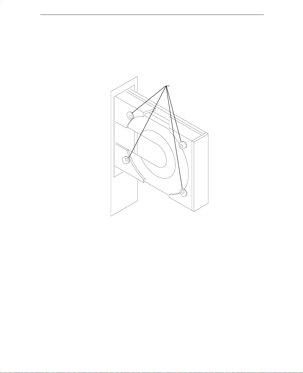
Replacing the Combo or Floppy Disk Drive.........................................41
Replacing the CD-ROM Drive..............................................................43
Replacing the System Hard Disk Drive.................................................44
Replacing the Auxiliary Hard Disk Drive.............................................47
Replacing the SCSI Termination Card..................................................51
Replacing the Riser Card.......................................................................52
Replacing the System Board..................................................................54
Replacing the Power Supply..................................................................58
Reprogramming the Flash EPROM...............................................................60
Changing the System Boot Sequence............................................................63
Chapter 5 Upgrading the System.............................................................65
Adding Main Memory...................................................................................65
Adding Internal SCSI Devices.......................................................................68
Adding External SCSI Devices.....................................................................70
Adding Option Boards...................................................................................71
PCI Option Boards.................................................................................72
ISA and PnP Option Boards..................................................................73
Using the System Configuration Utility........................................................75
ISA Boards with a Configuration File...................................................75
ISA Boards without a Configuration File..............................................77
Chapter 6 Using AMIBIOS Setup............................................................79
Starting AMIBIOS Setup...............................................................................80
Setup Menu....................................................................................................81
Standard Setup.......................................................................................81
Advanced Setup.....................................................................................82
Chipset Setup.........................................................................................83
Peripheral Setup.....................................................................................84
Page 7

Contents vii
Security Menu............................................................................................... 86
Password ............................................................................................... 86
Anti-Virus ............................................................................................. 87
Default Menu ................................................................................................ 87
Original ................................................................................................. 87
Optimal.................................................................................................. 88
Fail-safe................................................................................................. 88
Chapter 7 Troubleshooting...................................................................... 89
System Power................................................................................................ 89
System Boot.................................................................................................. 90
Sound93
Video94
Miscellaneous Hardware............................................................................... 94
Network......................................................................................................... 95
Appendix A Installing System Software................................................. 97
Installing Windows NT Workstation............................................................ 97
Installing Windows 95................................................................................ 103
Appendix B Hardware Information...................................................... 111
External Port Pinouts .................................................................................. 111
MIDI/Game......................................................................................... 111
Serial (COM)....................................................................................... 112
Ethernet AUI....................................................................................... 112
Ethernet 10Base-T............................................................................... 113
SCSI .................................................................................................... 113
Mouse and Keyboard .......................................................................... 114
Video................................................................................................... 114
Parallel ................................................................................................ 115
System Board Connector Pinouts ............................................................... 115
Floppy ................................................................................................. 116
ISA Bus J3........................................................................................... 116
ISA Bus J6........................................................................................... 117
Audio................................................................................................... 117
System Board Jumper Connectors.............................................................. 118
CPU Frequency................................................................................... 118
G95 VGA Mode Disable/Enable ........................................................ 120
Vibra 16S Sound Disable/Enable........................................................ 120
Power Supply Information.......................................................................... 120
DC Output Specifications ................................................................... 120
Cable Connectors................................................................................ 122
P1-P9 Connector Pinouts .................................................................... 122
Page 8

viii Contents
Returned Goods Authorization (RGA) Form
Warranty Procedure
Repair Depot Address Labels
Page 9

Preface
The TD-300, TD-400 Desktop Setup and Maintenance Guide contains
information for setting up, configuring, and servicing your desktop
workstation.
About This Document
The TD-300, TD-400 Desktop Setup and Maintenance Guide is organized as
follows:
♦ Chapter 1, “Getting Started,” describes how to set up the system
hardware and start the system, and other system information.
♦ Chapter 2, “Configuring the System,” describes how to configure the
video display and the TCP/IP networking software, and how to perform
any additional configuration tasks.
♦ Chapter 3, “Opening and Closing the Base Unit,” describes how to open
and close the system for maintenance and upgrades.
♦ Chapter 4, “Maintaining the System,” describes how to maintain the
system and replace its major components, and how to reprogram the
system’s flash EPROM.
♦ Chapter 5, “Upgrading the System,” describes how to upgrade the
system with new components.
♦ Chapter 6, “Using AMBIOS Setup,” describes how to configure the
system’s Basic Input/Output System (BIOS).
♦ Chapter 7, “Troubleshooting,” describes how to resolve common system
problems.
ix
Page 10

x Preface
♦ Appendix A, “Installing System Software,” lists software installed by
Intergraph, and describes how to install the operating system and
associated system software.
♦ Appendix B, “Hardware Information,” provides information for external
ports, system board connectors, system board jumper connectors, and the
power supply.
Document Conventions
Bold Commands, words, or characters that you key in literally.
Italic Variable values that you supply, or cross-references.
Monospace Output displayed on the screen.
UPPERCASE Names of files and directories. You can type filenames
and directory names in the dialog boxes or the command
line in lowercase unless directed otherwise.
SMALL CAPS Key names on the keyboard, such as D, ALT or F3.
CTRL+D Press a key while simultaneously pressing another key;
for example, press
CTRL and D simultaneously.
Finding Operating System Information
If you ordered your system with the Windows NT Workstation operating
system, you received printed and online Windows NT documentation from
Microsoft:
♦ For detailed information on using the Windows NT operating system,
refer to the online Windows NT Workstation System Guide, delivered on
CD-ROM with the operating system, and to Windows NT Help. You can
purchase a printed copy of the Windows NT Workstation System Guide
from Intergraph.
♦ For detailed information on installing and updating Windows NT, refer
to the Windows NT Workstation Installation Guide.
Page 11

Preface xi
If you ordered your system with the Windows 95 operating system, you
received printed and online Windows 95 documentation from Microsoft:
♦ For basic information on using Windows 95, refer to Introducing
Microsoft Windows 95, which is included in Microsoft’s Windows 95
software package.
♦ For detailed information on using Windows 95, refer to Windows 95
Help.
If you ordered your system with the Solaris 2.5 for x86 operating system,
you received printed and online Solaris documentation from Intergraph and
Sun Microsystems:
♦ For basic information on installing and setting up Solaris 2.5 for 86 on
your Intergraph TD-xxx system, refer to Intergraph’s Workstation
Software Configuration for Solaris 2.5 for x86.
♦ For additional information on installing and configuring Solaris 2.5,
refer to the documentation in Sun Microsystems’ Solaris software
package.
♦ For detailed information on using Solaris 2.5, refer to the online Solaris
User AnswerBook, delivered on CD-ROM with the operating system.
Getting Documentation and Training
You can purchase additional system or software product documentation from
Intergraph.
♦ In the United States, contact your sales account representative, call the
Intergraph Order Desk at 1-800-543-1054, or send a fax to
1-800-548-3318 to place an order. If you call or fax the Order Desk,
have the document numbers ready for the items you wish to purchase.
♦ At international locations, contact the Intergraph subsidiary or
distributor from which you purchased your Intergraph system or
software to place an order.
Page 12

xii Preface
To find information on training for Intergraph systems and products, or to
enroll in an available class, contact Intergraph Education Services at
1-800-240-3000.
Getting Telephone Support
If you experience problems with your Intergraph system or software, or have
questions about the information in this document, you can contact Intergraph
for help.
♦ In the United States, call the Customer Response Center at
1-800-633-7248 between the hours of 7:00 a.m. and 7:00 p.m. Central
Time, Monday through Friday (except holidays).
♦ At international locations, contact the Intergraph subsidiary or
distributor from which you purchased your Intergraph system or
software.
Have the following information readily available when you call:
♦ Workstation model number:
♦ Workstation serial number:
♦ Your name and telephone number.
♦ A brief description of the problem.
Locate the model and serial numbers on a label on the base unit carton, or on
a label on the back of the base unit. Write these numbers in the spaces
provided above.
Using the Intergraph Bulletin Board Service
Available 24 hours a day, 7 days a week, the Intergraph Bulletin Board
Service (IBBS) is an electronic forum for Intergraph customers to exchange
information with Intergraph’s technical and marketing staff, and with other
Intergraph customers. You can use the IBBS to get technical support
information, documentation and training information, programs, and
software updates and fixes. The IBBS is also available for you to give
suggestions, make inquiries, and report problems.
Page 13

Preface xiii
To connect to the IBBS:
➤
1. Set your communications protocol for eight (8) data bits, no parity,
one (1) stop bit, and any baud rate up to 14,400.
2. Using a modem, dial the IBBS number, 1-205-730-8786. You can dial
1-205-730-6504 if you are using a 2,400 baud connection.
3. Mirror sites are maintained for international locations. Information on
these sites is available on Intergraph Online, Intergraph’s World Wide
Web server. Refer to “Finding Intergraph on the Internet” for more
information.
4. When connected, respond to the login request by keying in your user
ID. If you have not connected before, key in new to create a user ID.
Follow the menus to find what you need. If you are new to computer
bulletin boards, the IBBS provides clear choices and plenty of online help.
A text file that explains IBBS commands and organization is available for
you to download.
If you have trouble connecting to or using the IBBS, call the System
Operator (Sysop) at 1-205-730-1413, or send a fax to 1-205-730-1110.
Using the Intergraph FAXLink
You can use the Intergraph FAXLink to get technical support information by
fax 24 hours a day, 7 days a week. To use FAXLink from a touch-tone
phone or fax machine phone:
♦ Call 1-800-240-4300 to get new user instructions, an index listing of
available documents, and an overview of the categories of available
information.
♦ Call 1-205-730-9000 to order the documents (up to 5 per call).
Follow the prompts provided to locate and deliver the information you need.
Page 14

xiv Preface
Finding Intergraph on the Internet
You can find Intergraph on the Internet in the following ways:
♦ If you have a World Wide Web browser, connect to Intergraph Online,
Intergraph’s Web server, at http://www.intergraph.com.
♦ If you have an application that allows you to transfer files to and from a
system using File Transfer Protocol (FTP), connect to Intergraph’s
anonymous FTP site at ftp.intergraph.com.
♦ If you have an application that allows you to search and retrieve files
using Gopher, connect to Intergraph’s Gopher site at
gopher.intergraph.com.
♦ You can get information from Intergraph’s email server at
info@intergraph.com. Put HELP in the body of the message (the
subject line is ignored) to get information on such subjects as
Intergraph’s online services and where to get World Wide Web
browsers.
Learning About System Ergonomics
Please read the Ergonomics Guide included with your Intergraph system.
This document provides valuable information on ways to minimize repetitive
stress injuries for persons working with a computer.
Page 15

Chapter 1
Getting Started
The TD-300 and TD-400 desktop workstations are easy to set up and use.
Follow the instructions in this chapter to set up and start your system.
Unpacking
If you have not removed everything from the shipping cartons, do so now
and verify you have the following equipment. The workstation carton
contains the following items:
♦ Workstation base unit
♦ Keyboard
♦ Mouse
♦ Footstands
♦ Base unit power cord
♦ Operating system and system software carton
1
The carton for the operating system and system software contains the
following items.
♦ Windows NT, Windows 95, or Solaris 2.5 for x86 software (CD-ROM
and setup diskettes)
♦ Intergraph G95 video display driver diskette
♦ Intergraph Quick-Fix Engineering (QFE) diskette
♦ Intergraph System Utilities (SYSUTIL) diskette
♦ Primax mouse driver diskette (Windows 95 only)
♦ Intergraph TD-300, TD-400 Desktop Online Reference diskette
Note: The workstation is delivered with the operating system and
associated system software installed on the system’s hard disk drive.
Page 16

2 Chapter 1 - Getting Started
If you ordered a monitor from Intergraph, its carton contains the following
items.
♦ Monitor
♦ Monitor power cord
♦ Video cable
♦ Documentation
Note: If any of the base unit or monitor parts were not delivered, call the
Customer Response Center immediately at 1-800-633-7248
Retain all packaging materials. If you return equipment for repair, you must
return it in the original packaging to obtain warranty service (if provided
under your contract agreement).
Setting Up
Before you begin setting up your workstation, determine where you want to
place the system. Keep these guidelines in mind:
♦ Place the base unit in an area where air can circulate freely around it.
The back panel of the base unit should have at least a 3-inch clearance,
and the sides should have at least a 1-inch clearance unless the base unit
is set in the vertical position.
♦ Do not expose the system to high levels of dust, smoke, or moisture.
♦ Place the system in an area where the temperature range stays between
10 °C and 26 °C (50 °F to 80 °F). The optimum operating temperature is
21 °C (70 °F).
♦ Place the system in an area where the humidity stays between 20% and
80% (non-condensing). The optimum operating humidity is 50% (noncondensing).
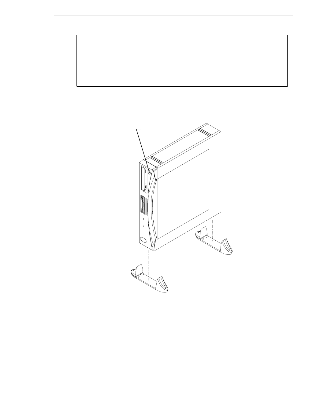
To set up the workstation:
➤
1. If putting the base unit in a vertical position, set the footstands on the
bottom of the base unit as shown in the following figure. Place the
back footstand between the ribs on the back and side of the base unit.
Page 17
Chapter 1 - Getting Started 3
WARNING
To avoid personal injury or equipment damage, and to allow proper
airflow, you must use the footstands when setting the base unit in the
vertical position.
Note: Ensure the power switch is at the top when setting the base unit in
the vertical position.
Power Switch
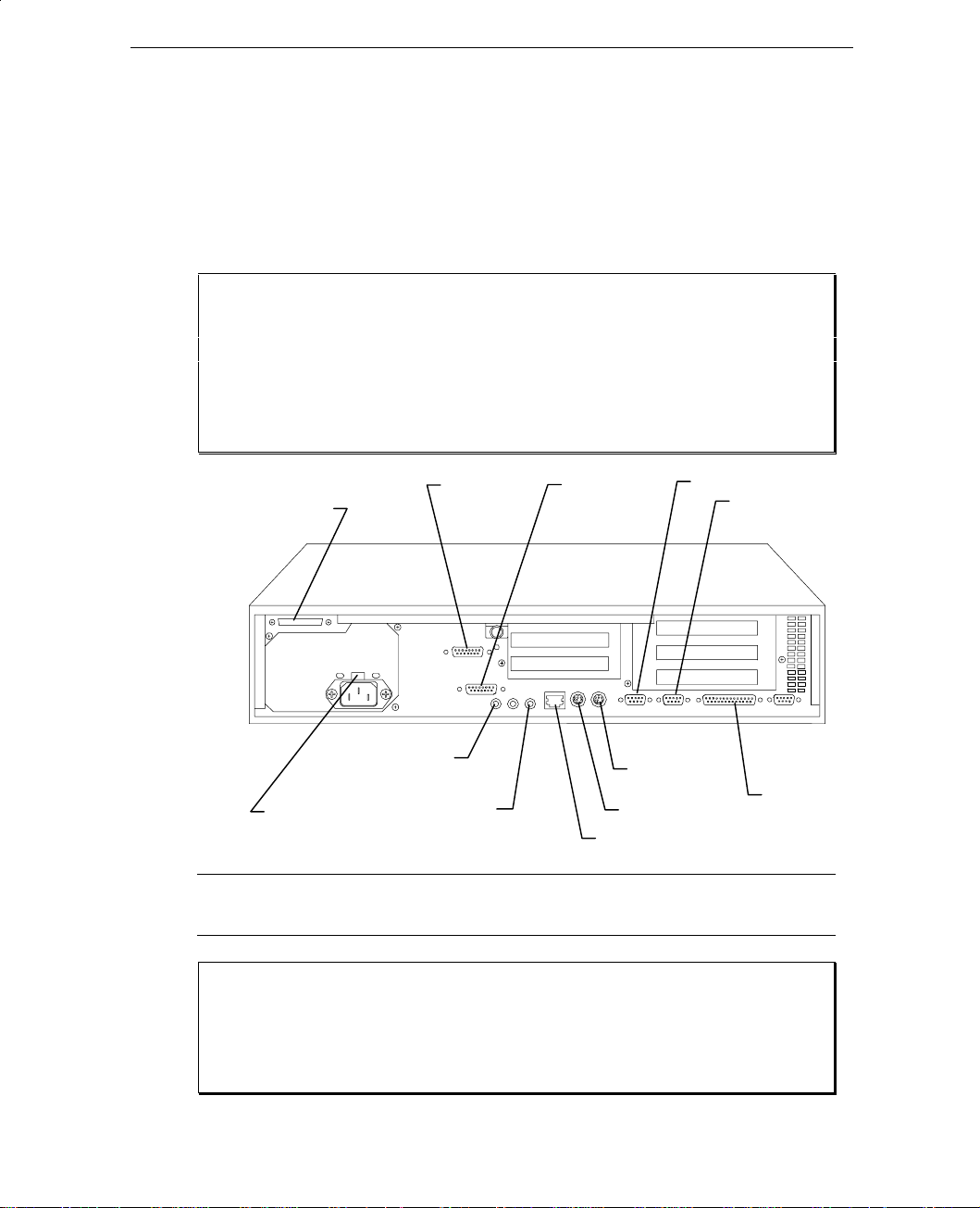
2. Connect the keyboard cable to the keyboard port on the back of the
base unit. Refer to the following figure.
3. Connect the audio cables (bundled with the keyboard cable) to the
audio jacks. The cable labeled Mic connects to the microphone jack,
and the cable labeled audio connects to the line out jack. Refer to the
following figure.
Page 18
4 Chapter 1 - Getting Started
CO
4. Connect the mouse cable to the mouse port on the back of the base
unit. Refer to the following figure.
5. Connect the remaining cables, such as Ethernet (AUI or 10Base-T
ports), printer (parallel port), and modem cables (COM1 and COM2
ports) to their ports on the back of the base unit. Refer to the
following figure.
If you are using cables not supplied by Intergraph, you must use
shielded cables to prevent excessive electromagnetic interference
(EMI). Intergraph cables are designed to reduce the amount of EMI
produced by the system.
Fast
SCSI-2
WARNING
Ethernet
AUI
MIDI
M1
COM2
AC Voltage
Switch
Microphone
Line Out
Mouse
Keyboard
Ethernet 10Base-T
Parallel
Note: The ports on the back on the base unit are labeled using PC 95
compliant icons.
WARNING
Do not connect a MIDI or game cable to the Ethernet AUI port. This
will short out the local area network on which the system resides.
Page 19

6. Set the power supply range switch to the proper setting for your
country. If you do not know the voltage for your location, contact
your local utilities.
7. Ensure the power switch on the front of the base unit is in the out
position. If the power switch is in, power will be applied when the
base unit power cord is plugged into the AC outlet.
8. Connect the power cords for the monitor and base unit to an
Uninterruptible Power Supply (UPS) or a grounded three-prong AC
wall outlet. Then connect the power cords to the base unit and the
monitor.
9. Connect the video cables as described in “Connecting the Video
Cables.”
10. Start the system as described in “Starting the System.”
Connecting the Video Cables
Chapter 1 - Getting Started 5
This section describes connecting the video cables for systems using the G95
video display adapter integrated on the system board, or installed G95 video
display adapter boards for a la carte and dual-screen systems.
Connect the video cable for each monitor to a Video port on the back of the
base unit and to the monitor.
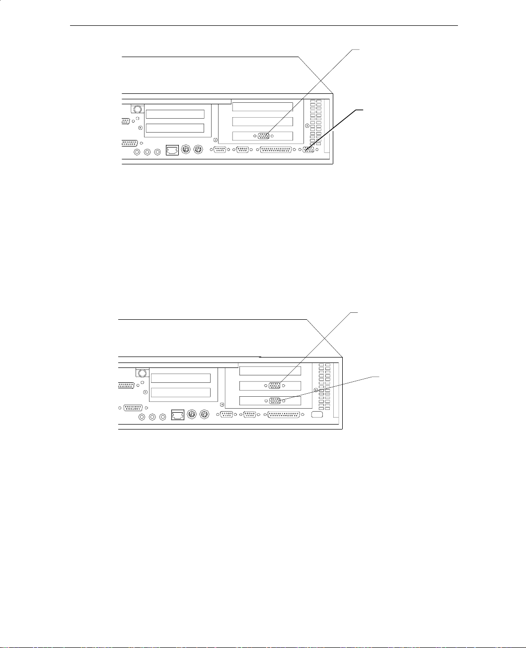
For workstations with G95 graphics on the system board:
➤
1. Connect the video cable to the Video port adjacent to the parallel port
and to the monitor. Refer to the following figure.
2. For dual-screen configurations, connect the video cable for the
secondary monitor to the Video port in PCI slot 3 and to the monitor.
Refer to the following figure.
Page 20
6 Chapter 1 - Getting Started
For a la carte workstations:
➤
1. Connect the video cable to the Video port in PCI slot 2 and to the
monitor. Refer to the following figure.
2. For dual-screen configurations, connect the video cable for the
secondary monitor to the Video port in PCI slot 3 and to the monitor.
Refer to the following figure.
Video Port
(Secondary
Monitor)
Video Port
(Single or
Primary Monitor)
Starting the System
The workstation is delivered with the operating system installed on the
system’s hard disk drive. After setting up the system, you can start it, and
start the operating system for the first time.
Video Port
(Single or
Primary Monitor)
Video Port
(Secondary
Monitor)
Page 21
Chapter 1 - Getting Started 7
Power
WARNING
If the AC voltage switch on the back of the base unit is not set correctly
for your location, the workstation will be seriously damaged when you
press the power switch.
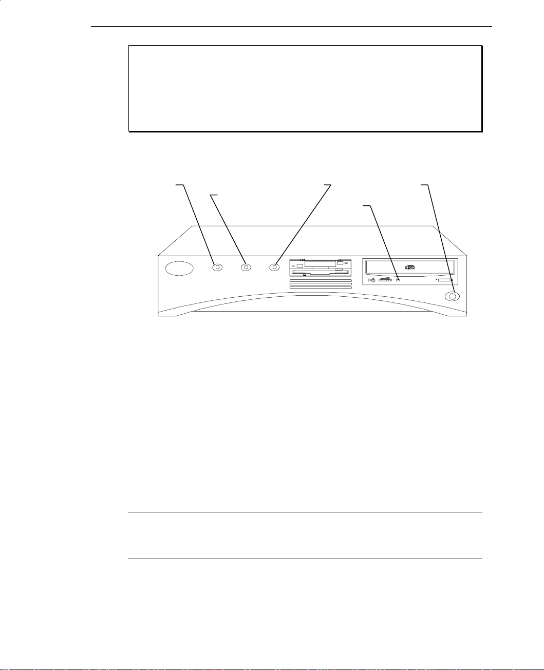
The following figure shows the front of the base unit.
Reset Disk
Switch Activity On LED Switch
LED CD-ROM
LED
To start the system:
➤
Power
1. Press the power switch on the base unit and the power switch on the
monitor to turn on power to the system. The following events occur:
♦ The power on LED lights green.
♦ The CD-ROM drive LED blinks green and amber.
♦ The BIOS boot screen displays the American Megatrends logo.
♦ A boot screen or setup screen displays.
2. Refer to the appropriate procedure (following) to start the operating
system for the first time.
Note: For information on starting and configuring the Solaris 2.5 for x86
operating system, refer to Intergraph’s Workstation Software
Configuration for Solaris 2.5 for x86.
Page 22

8 Chapter 1 - Getting Started
Starting Windows NT for the First Time
To start Windows NT for the first time:
➤
1. At the initial boot screen, select the following option:
Windows NT Workstation 3.51 [VGA Mode]
After additional messages display, Windows NT Workstation starts in
VGA mode, allowing you to log on and configure your system’s date,
time, and video display.
2. Press
3. Select OK or press
4. Use the Date/Time application in the Windows NT Control Panel to
5. Configure the video display and TCP/IP networking software as
6. Create an Emergency Repair Disk for your system using the Windows
Note: If your system came pre-configured from Intergraph, you can run
CTRL+ALT+DELETE to display the Windows NT Workstation
logon dialog. The first time the logon dialog displays,
Administrator displays in the Username box. The From and
Password boxes are blank.
ENTER to log on to Windows NT Workstation. For
instructions to create a user account and join a workgroup or domain,
refer to the online Windows NT Workstation System Guide.
set the system date and time. Refer to the online Windows NT
Workstation System Guide for instructions on using the applications in
the Control Panel.
described in Chapter 2, “Configuring the System.”
NT Repair Disk utility (RDISK.EXE). The files on the Emergency
Repair Disk can restore the original contents of a damaged Windows
NT Registry (that is, at the time Windows NT was installed), along
with the standard Windows NT drivers. Refer to Windows NT Help
for information on creating an Emergency Repair Disk, and to the
Windows NT Workstation Installation Guide for information on using
it.
the Repair Disk utility from an icon in the Startup group of
Program Manager.
Page 23

Chapter 1 - Getting Started 9
Starting Windows 95 for the First Time
To start Windows 95 for the first time:
➤
1. At the initial Windows 95 Setup screen, select Next.
2. Select the regional setting that most closely matches where you live.
3. Select the appropriate keyboard layout for your location.
4. When prompted for User Information, key in your name and the name
of your company, if appropriate.
5. Read the Windows 95 license information; then select Next.
6. Read the Windows 95 License Agreement. Press
the scroll bar to view the text; then select I Accept the Agreement.
7. When prompted, key in the 20-digit Product Identification Number,
found on the Certificate of Authenticity on the cover of Introducing
Microsoft Windows 95.
Note You must key in the Product Identification Number before you can
continue Setup. You cannot start Windows 95 for the first time if
you do not know the number.
8. At the Configuring the Computer prompt, select Next. Windows 95
installs your system devices.
9. When prompted, select Finish to continue.
10. Remove the diskette (if one is inserted) from the floppy disk drive;
then select OK. The system restarts.
11. Key in a username and a password for your Windows 95 user account.
If you do not want to create a user account at this time, select Cancel.
PAGE DOWN or use
12. If you are prompted to set up the Microsoft Exchange Inbox, select
Yes or No, as appropriate; then select Next. Follow the prompts, as
necessary.
Page 24

10 Chapter 1 - Getting Started
13. If you are prompted to set up your Microsoft Mail account, key in the
path to your local Microsoft Mail post office. Key in the name and
the password for your mailbox. If you do not want to create a mailbox
at this time, select Cancel; then select Yes to confirm.
14. You must install a printer before you can print from Windows 95.
Select Local or Network, as appropriate. If you do not want to install a
printer at this time, select Cancel.
15. Select the appropriate time zone for your location; then select Close.
The system restarts.
16. Key in a username and a password for your Windows 95 user account.
If you do not want to create a user account at this time, select Cancel.
The Windows 95 desktop displays.
17. Configure the video display and TCP/IP networking software as
described in Chapter 2, “Configuring the System.”
18. Create a Windows 95 Startup Diskette for your system. The files on a
Startup Diskette can restore the original contents of a damaged
Windows 95 Registry (that is, at the time Windows 95 was installed),
along with the standard Windows 95 drivers. Refer to Windows 95
Help for information on creating and using a Startup Diskette.
About Installed System Software
Intergraph shipped your TD-xx workstation with the operating system and
associated system software installed on the system’s hard disk drive. On a
system running Windows NT Workstation or Windows 95, the following
system software is installed:
♦ Operating system driver software for VGA video display.
♦ Driver software for Intergraph’s video display adapter.
♦ Driver software for Intergraph’s on-board networking adapter.
♦ Operating system network software (TCP/IP and NetBEUI).
♦ Driver software for Intergraph’s on-board sound processor.
The default file system is File Allocation Table (FAT). On a system running
Windows NT Workstation, if you want to change the FAT file system to
NTFS, you can do one of the following:
♦ Use the Windows NT CONVERT.EXE program.
Page 25

♦ Re-install Windows NT Workstation with the NTFS file system.
You should change to NTFS immediately after setting up the system, before
you install applications programs and begin creating files and directories.
When using CONVERT.EXE, you must manually set permissions on files
and directories; this occurs automatically when re-installing the operating
system with NTFS. For more information on converting file systems, refer
to the Windows NT Workstation Installation Guide. For more information
on securing directories and files, refer to the online Windows NT
Workstation System Guide.
For information on software installed on a system running the Solaris 2.5 for
x86 operating system, refer to Intergraph’s Workstation Software
Configuration for Solaris 2.5 for x86 (delivered with Intergraph workstations
running Solaris 2.5 for x86).
Re-Installing System Software
If you need to re-install the Windows NT Workstation or Windows 95
operating system for any reason, refer to Appendix A, “Installing System
Software” for instructions.
Chapter 1 - Getting Started 11
For instructions on re-installing the Solaris 2.5 for x86 operating system,
refer to Intergraph’s Workstation Software Configuration for Solaris 2.5 for
x86 (delivered with Intergraph workstations running Solaris 2.5 for x86).
Observing System Precautions
Observe the following precautions when using the system.
♦ When restarting the system, use the operating system controls instead of
pressing the reset button or turning the power switch off and on. Use the
reset button and power switch only when instructed, or as the last
alternative for restarting the system.
♦ Never turn the base unit off when the disk access LED is on.
♦ After powering off the base unit, wait at least 30 seconds before
powering on again to allow the system to power cycle.
Page 26
12 Chapter 1 - Getting Started
♦ Periodically run virus scan software to ensure your system files are not
corrupted.
♦ If you placed the system in a vertical position, press the eject/load button
to open the CD-ROM drive tray. Rotate or slide at least three of the
media tabs so that when you insert a compact disc, it will not fall out.
Media Tabs
Using the Online Reference
Detailed technical information about your workstation is delivered in an
Online Reference document. This Windows Help-based document is
delivered on diskette in the form of a self-extracting archive file named
TDDTOR.EXE.
To install and display your system’s Online Reference:
➤
1. Insert the diskette containing the Online Reference into the floppy
diskette slot of the combo drive.
Page 27

Chapter 1 - Getting Started 13
2. Copy the TDDTOR.EXE and README.TXT files from the diskette
to a directory on your system’s hard disk drive; then remove the
diskette from the combo drive.
3. Open TDDTOR.EXE. The following files are extracted:
G95.CNT
G95.HLP
SUPPORT.CNT
SUPPORT.HLP
TDDTOR.CNT
TDDTOR.HLP
4. Ensure the extracted files remain in the same directory for the Online
Reference to work properly. After the files have been extracted, you
can delete TDDTOR.EXE from the system’s hard disk drive.
5. Open TDDTOR.HLP to display the Online Reference.
You can obtain the latest version of your system’s Online Reference from the
Intergraph Bulletin Board Service (IBBS) or Intergraph’s FTP site.
To obtain Online Reference updates:
➤
1. From the IBBS login, go to Intergraph Product Centers → Systems
and Networking → File Libraries → Technical Notes. From the FTP
login, go to /bbs/ssd/note.
2. Look for self-executing (.EXE) archive files whose names start with
TD and end in OR (such as TDDTOR.EXE or TDDSOR.EXE). The
file descriptions in the IBBS or the FTP index should note the title and
part number of each Online Reference.
3. Download the file to your system.
4. Open the .EXE file and review the README.TXT file. Follow the
instructions in the README.TXT file to properly install the new
Online Reference.
Page 28

14 Chapter 1 - Getting Started
Obtaining Windows NT Updates
Microsoft Service Packs contain the latest improvements and system fixes
that have been requested for the Windows NT operating system. Service
Packs are created by Microsoft approximately every three months. You may
obtain Service Packs from the following sources:
♦ Intergraph Bulletin Board Service (IBBS)
♦ Microsoft Inside Sales
♦ CompuServe
♦ Microsoft FTP locations
The service packs are for post-release support only. The product media for
Windows NT will not include improvements or fixes in a given Service Pack
until the next major Windows NT release.
CAUTION
If Intergraph provides a Service Pack through the IBBS, it has been
certified against Intergraph hardware as described with the
announcement of its availability. If you obtain a Service Pack from any
other source, be aware that it may not have been certified with your
Intergraph hardware.
Ensuring PC Card Support
Your system has a PC Card slot for use with devices based on standards
developed by the Personal Computer Memory Card International
Association (PCMCIA). Windows NT Workstation 3.51, Windows 95, and
Solaris 2.5 for x86 provide support for PC Card devices, but not all devices
are supported. Before inserting or removing a PC Card device, you must
shut down the system.
Additionally, some PC Card devices require that specific system resources
be reserved for proper operation. If so, run the System Configuration Utility
(SCU), as described in Chapter 5, to reserve the resources. Refer to the
documentation supplied with your PC Card device for information about the
required system resources.
Page 29

Chapter 2
Configuring the System
After setting up the system hardware and starting the system for the first
time, you can configure it for your use. Follow the instructions in this
chapter to configure a system running Windows NT Workstation or
Windows 95.
Note: For instructions on configuring the system when it is running Solaris
2.5 for x86, refer to Intergraph’s Workstation Software
Configuration for Solaris 2.5 for x86.
Before You Begins
Before you begin configuring the system, get and record the following
TCP/IP networking information from your network administrator:
15
♦ Internet Protocol (IP) address for
your system:
♦ IP subnet mask for your system:
♦ IP domain name for your network:
♦ IP address for your network’s
default gateway:
♦ IP addresses for your network’s
Domain Name System (DNS)
servers, if any:
Page 30

16 Chapter 2 - Configuring the System
The Windows NT delivery media contain software and drivers for both
Reduced Instruction Set Computing (RISC)- and Intel-based systems. When
installing Windows NT distribution files, make sure to install them from the
\I386 directory (the Intel software directory) on the delivery media. For
example, if you are installing a device driver from the Windows NT
CD-ROM, key in the following when asked for the path to the file, where
drive is the drive letter for the CD-ROM drive:
drive:\i386
Re-Installing System Software
If you need to re-install the Windows NT Workstation or Windows 95
operating system for any reason, refer to Appendix A, “Installing System
Software” for instructions.
For instructions on re-installing the Solaris 2.5 for x86 operating system,
refer to Intergraph’s Workstation Software Configuration for Solaris 2.5 for
x86 (delivered with Intergraph workstations running Solaris 2.5 for x86).
About the System’s Video Display
When you start your system for the first time, it uses the installed operating
system’s VGA display driver to run the video display. To enable the system
to use its installed G95 video display adapter at other display resolutions,
you must configure the video display to use the Intergraph G95 video display
driver. This driver is installed on the system’s hard disk, and is also
delivered on a backup diskette.
The Intergraph G95 video display adapter is based on the Matrox 2064W
video display engine. G95 provides resolutions up to 1600 x 1280 in 256,
65,000, and 16.7 million colors, and screen refresh rates up to 120 Hz. G95
communicates through an optimized PCI interface capable of 120 MB per
second transfers. If your system is running Windows NT Workstation 3.51,
G95 provides more advanced features, including 3D acceleration for
OpenGL.
Page 31

Chapter 2 - Configuring the System 17
The base version G95 graphics provides 2 MB of dual ported WRAM
(Window RAM), upgradable to 4 and 8 MB. Additional memory increases
the number of colors available at each resolution, enabling you to work in
true color and 3D at higher resolutions.
For more information on the G95 video display adapter and driver, refer to
the README.TXT file delivered with the G95 video display driver.
Configuring a System Running Windows NT
Workstation
To configure a system running Windows NT Workstation, you must
configure the video display and the TCP/IP networking software.
Configuring the Video Display
Use the Display application in the Windows NT Control Panel to change the
configuration of the G95 video display driver.
To change G95 video display configuration:
➤
1. Open Display in the Windows NT Control Panel. The Display
Settings dialog displays.
Page 32

18 Chapter 2 - Configuring the System
Note: Changing one display setting may cause the others to shift
automatically. For example, if you select 1024 x 768 in the Desktop
Area, the Refresh Frequency may automatically change to a
supported rate for that resolution.
2. Change the settings in the Display Settings dialog as follows:
♦ Use Color Palette to select the number of colors for the display.
♦ Use Desktop Area to change the resolution for the display. Larger
resolutions cause items to look smaller on the screen.
Note: If your system has dual G95 displays, you are offered desktop
resolutions that are horizontally or vertically doubled in size,
corresponding to the side-by-side or vertical logical stacking of the
video monitor display areas. For example, a pair of monitors sideby-side each running at 1600 x 1200 display resolution would be
represented in the Display Settings Dialog as an available 3200 x
1200 display resolution. See “Selecting a Dual-Screen Style” in this
chapter for more information on dual-screen displays.
♦ Use Font Size to select a font size for the display type. The
options supported are usually Small Fonts and Large Fonts.
♦ Use Refresh Frequency to select the refresh rate for the video
display. For G95, however, you should use the MGA Monitor
utility to completely characterize your monitor at all of the
resolutions it is equipped to display, to ensure the best possible
performance.
3. Select Test to see how your selected settings work with your monitor.
Note: You can select List All Modes to display all of the resolutions
supported by the display driver. Select the display mode you want to
use from the Valid Modes dialog, and select Test to see how the
resolution looks with your monitor.
4. When the selected settings are satisfactory, select OK.
5. Restart the system.
Page 33

Chapter 2 - Configuring the System 19
6. After restarting the system, if windows are displayed partially off the
screen, use the mouse to double-click the title bar and move the
windows back onto the screen. You can also bring up the task list (by
double clicking on the Windows NT background) and click the
Cascade button to cascade the windows.
By default, the G95 display driver assumes your system has a 60 Hz monitor.
If your monitor is capable of higher refresh rates, you should run the MGA
Monitor application to select a different monitor with a higher refresh rate.
To change the monitor refresh rate:
➤
1. Open MGA Monitor in the Windows NT Control Panel. The MGA
Monitor Selection dialog displays.
2. Select the appropriate monitor from the Monitor List. If your
system’s monitor is not listed, select one with a maximum refresh rate
matching the one your system uses. An MGA.INF file will be created
in the SystemRoot\SYSTEM32 directory.
Note: In a multiple G95 configuration, the MGA.INF setting affects all
monitors. Intergraph recommends that you select a monitor that
is compatible with the least-capable monitor used by your
system.
To test the new monitor selection:
➤
1. Open Display in the Windows NT Control Panel.
2. Select the resolution and pixel depth you want to test.
Page 34

20 Chapter 2 - Configuring the System
3. Select Test. If the display is satisfactory, go to step 6. If not,
continue.
4. If your monitor does not display a stable test screen, the parameters
set by the MGA.INF file are not suitable for your monitor. Select
Cancel to close Display.
5. Run MGA Monitor again to select a different monitor.
6. Repeat steps 1 through 3 to test the video display with the new
monitor selection. When the display is satisfactory, close Display.
7. Restart the system.
No resolution higher than the limit imposed by a monitor selection appears
in the Display mode list. Deleting the MGA.INF file removes all monitor
limits to the resolution, although the refresh rate defaults to 60 Hz.
Changing the Dual-Screen Style
If your system has dual G95 displays, the G95 video display driver treats the
combined display area of the dual screens as a single canvas that covers both
screens. In this Full Canvas style, windows centered on the canvas are split
between the two screens. This includes most system dialog boxes.
When the system is running Windows NT 3.5 (or later), the G95 video
display driver can treat the left or top monitor as the primary screen, while
the full desktop extends across both screens. This Primary Left/Top style
results in different windowing behaviors than those displayed by default,
including the following:
♦ Dialogs display fully and applications maximize on the primary screen.
♦ Most centered windows center on the primary screen.
♦ Testing a dual-screen mode from the Display Properties application
actually tests only the corresponding single-screen mode.
♦ Toolbars may not use the whole desktop.
♦ Screen savers may work only on the primary screen.
Page 35

Chapter 2 - Configuring the System 21
To change the dual-screen style, you must edit the Windows NT Registry.
WARNING
Do not change values in the Registry other than as directed. If you
introduce incorrect values into the Registry, you may cause serious
operating system problems, and you may have to reinstall Windows NT.
If you change values in the Registry that make your system unusable,
you may be able to restart the system and use the Last Known Good
Configuration option to undo the damage. Refer to the Windows NT
Workstation Installation Guide for more information on the Last
Known Good Configuration option.
To change the dual-screen style:
➤
1. Start the Registry Editor (REGEDT32.EXE) to open the Registry.
2. Open the following subkey in the Registry:
HKEY_LOCAL_MACHINE\SYSTEM\CurrentControlSet\Services\
mgax64\Device0
3. In the right-hand pane of the Registry Editor window, select
User.CenterDialogs.
4. From the Edit menu, select DWORD.
5. To enable Primary Top/Left style, type 0 into the Data box. To enable
Full Canvas style, type 1 into the Data box.
6. Select OK.
7. Exit from the Registry Editor.
8. Restart the system.
Page 36

22 Chapter 2 - Configuring the System
Changing the Default Video Display Driver
After configuring the video display and restarting the system, you can
configure the system to use the Intergraph G95 video display driver by
default.
To change the default video display driver:
➤
1. Open System in the Windows NT Control Panel. The System dialog
displays.
2. Under Operating System, select Windows NT Workstation
3.51 from the Startup list.
3. Select OK.
Correcting Video Display Problems
If the system’s video display is black, not synchronized, or distorted after
you restart the system, you may have a video configuration problem. Do not
press
CTRL+ALT+DEL to log on to the Windows NT operating system.
Instead, try to correct the problem by using the Last Known Good option to
return the system to the last know good configuration recorded by Windows
NT.
To use the Last Known Good option:
➤
1. Power down and restart the system.
2. Press the space bar at the following prompt:
Press space bar NOW to invoke the Last Known Good Menu
If using the Last Known Good option fails to correct the video display
problems, you can obtain a functional video resolution by restarting the
system in VGA mode.
To restart the system in VGA mode:
➤
1. Power down and restart the system.
Page 37

Chapter 2 - Configuring the System 23
2. At the boot screen, select the following option:
Windows NT Workstation 3.51 [VGA mode]
Check for the following common video configuration problems and
solutions:
♦ A multi-sync monitor is selected, but a graphics display device with
different video timings (such as an Intergraph InterVue monitor) is
connected to the system. Select the appropriate monitor type as
described previously.
♦ The monitor selection set by the MGA Monitor application is
inappropriate for the multi-sync monitor attached to the system. Restart
the system in VGA mode, then select a new monitor as described
previously.
♦ A graphics resolution and color depth has been selected that exceeds
installed Windows RAM (WRAM) display memory. Restart the system
in VGA mode, then open Display in the Control Panel to re-install and
configure the G95 display driver as described in Appendix A, “Installing
System Software.”
Restart the system and select
reconfigured video display driver. If problems persist, contact the Intergraph
Customer Response Center for help.
Windows NT Workstation 3.51 to use the
Configuring TCP/IP Networking
Configure the TCP/IP networking software using the networking information
you recorded at the beginning of this chapter.
To configure TCP/IP networking software:
➤
1. Open Network in the Windows NT Control Panel. The Network
Settings dialog displays.
2. Select Change next to the Computer Name field. The Computer Name
dialog displays.
3. Type a name for the computer and select OK.
Page 38

24 Chapter 2 - Configuring the System
4. If appropriate, select Change next to the Workgroup field. The
Domain/Workgroup Settings dialog displays.
5. Type a new workgroup name and select OK.
6. Select TCP/IP Protocol from the Installed Network Software list, and
then select Configure. The TCP/IP Configuration dialog displays.
7. Type your system’s Internet Protocol (IP) address and IP subnet mask,
and the IP address of your network’s default gateway.
8. If your network uses the Domain Name System (DNS), select DNS.
The DNS Configuration dialog displays.
9. Type your network’s IP domain name and the addresses of your
network’s DNS servers, and then select OK.
10. In the TCP/IP Configuration dialog, select OK.
11. Restart the system.
Configuring a System Running Windows 95
To configure a system running Windows 95, you must configure the video
display and the TCP/IP networking software. You may also want to perform
some additional configuration tasks for your convenience and security.
Configuring the Video Display
Use the Display Properties application available from the Windows 95
desktop to change the configuration of the G95 video display driver. First,
make sure you have selected the appropriate video display adapter and
monitor type.
To check and change the video display adapter and monitor:
➤
1. Right-click the Windows 95 desktop. A menu displays.
2. Select Properties. The Display Properties dialog displays.
3. Select the Settings tab.
Page 39

Chapter 2 - Configuring the System 25
4. Select Change Display Type. The Change Display Type dialog
displays.
5. To change the video display adapter, select Change under Adapter
Type. To change the monitor type, select Change under Monitor
Type.
6. Select Show all devices. From the list, select the appropriate video
display adapter and monitor type.
7. If you want to change the video display adapter or monitor type, and
you have a diskette from the device manufacturer, insert the diskette
into the floppy disk drive and select Have Disk. Follow the prompts
to install the device from the diskette. If you do not have a diskette
from the device manufacturer, select Show all devices, and select your
adapter or monitor type from the list.
8. Select OK. The Change Display Type dialog displays.
9. If your monitor is Energy Star compliant, select the Monitor is Energy
Star compliant check box.
10. Select Close. The Display Properties dialog displays.
Page 40

26 Chapter 2 - Configuring the System
11. Select Apply.
By default, the G95 display driver assumes your system has a 60 Hz monitor.
If your monitor is capable of higher refresh rates, you should run the MGA
Monitor application to select a different monitor with a higher refresh rate.
To select a monitor:
➤
1. From the Windows 95 Start menu, select Programs, select MGA
Millennium PowerDesk, and then select MGA Monitor Program.
The MGA Millennium Monitor Selection dialog displays.
2. Clear the Use Windows 95 Monitor check box. The monitor selection
you make in these steps overrides the Windows 95 monitor selection.
3. Select Selection. The Monitor Selection dialog displays.
4. Highlight the appropriate monitor and select OK. If your monitor is
not listed, or if you are unsure which monitor to select, refer to the
README.TXT file delivered with the G95 video display driver.
5. Select Test. The Monitor Test dialog displays. Use this dialog to test
your monitor selection against various combinations of resolution and
pixel depth. The combinations available depend on your system
configuration.
6. Select Test to activate the test screen. Press
screen. When finished testing, select Close. If testing reveals display
ESC to exit the test
Page 41

Chapter 2 - Configuring the System 27
problems, return to the Monitor Selection dialog to change your
monitor selection.
7. When you have selected and tested your monitor, select Save and
Exit.
8. If there is a diskette in the floppy disk drive, remove it; then select
Restart Windows to restart the system.
Use the MGA Settings tab in the Display Properties dialog to customize and
save display schemes, each containing unique display and desktop sizes,
color palettes, and font sizes. You can also customize advanced features
such as geometric shape acceleration, 3D acceleration, hotkeys, and popup
window centering.
To change G95 video display configuration:
➤
1. Right-click the Windows 95 desktop. A menu displays.
2. Select Properties. The Display Properties dialog displays.
3. Select the MGA Settings tab.
Page 42

28 Chapter 2 - Configuring the System
4. Select the size of the display and desktop areas to set the video display
resolution. The display and desktop combination you select limits the
color palettes available.
Note: The virtual desktop cannot be smaller than the display area. Select a
desktop area larger than the display area to permit extended screen
manipulation, such as side-by-side full-page viewing of a two-page
document, or large, maximized spreadsheets without redraw delays.
5. To set the display and desktop areas to the same size, select the Lock
Display check box.
6. Select a color palette for the display. The amount of memory on the
display adapter determines which color palettes are available. The
color palette you select limits the size of the display and desktop
areas. The following table shows the supported desktop area and color
palette combinations.
Desktop Area
256 65,565 16.7 M
640 x 480 2 MB 2 MB 2 MB
800 x 600 2 MB 2 MB 2 MB
1024 x 768 2 MB 2 MB 4 MB
1152 x 864 2 MB 2 MB 4 MB
1280 x 1024 2 MB 4 MB 4 MB
1600 x 1200 2 MB 4 MB 8 MB
Color Palette
7. Select a font size for the display.
8. To save this video configuration, select Save As and type a scheme
name in the Display Scheme box.
9. Select Advanced to set the geometric shape acceleration, 3D
acceleration, hotkeys, and popup window centering. The MGA
Advanced Settings dialog displays.
Page 43

Chapter 2 - Configuring the System 29
10. Select the Performance tab, and then select the appropriate check
boxes to enable or disable geometric shape acceleration or 3D
acceleration. Enabling 3D acceleration reduces the display area and
color palette combinations available, as shown in the following table.
Color Palette
Desktop Area
256 65,565 16.7 M
640 x 480 2 MB 2 MB 8 MB
800 x 600 2 MB 4 MB 8 MB
1024 x 768 4 MB 8 MB
1152x864 4 MB 8 MB
1280x1024 4 MB 8 MB
1600x1200 8 MB
-- --
--
--
--
Note: To use the G95 graphics 3D Acceleration feature, you may have to
install more video memory. The G95 video display adapter supports
up to 8 MB of Window RAM (WRAM). Refer to your system’s
hardware documentation for information on the location of the
connectors for the addition of WRAM modules.
11. Select the PowerDesk tab to enable and specify hotkeys. You can set
hotkeys for the following features:
♦ PixelTOUCH toggles the display zoom between x1, x2, and x4.
♦ CenterWINDOW centers the display around the active window.
♦ PanLOCK locks the view to the current display area.
To enable and specify a hotkey, select the appropriate field, and then
press and hold ctrl, alt, and/or shift while pressing a letter key.
12. Check the Center popup window check box on the PowerDesk tab to
center popup menus in the current display area, instead of centering
popup menus on the virtual desktop.
13. Select OK.
14. Restart the system.
You can use the MGA Quick Access dialog to rapidly switch between four
display modes, and to change such features as the PixelTOUCH zoom,
Page 44

30 Chapter 2 - Configuring the System
PanLOCK, and CenterPOPUP. To display the Quick Access dialog, select
Programs from the Windows 95 Start menu, select MGA Millennium
PowerDesk, and then select Quick Access. For more information, refer to
the ONLINE.DOC file in the MGA Millennium PowerDesk program group.
Correcting Video Display Problems
If the display is black, not synchronized, or distorted after restarting the
system, you may have a video configuration problem. Check for the
following common video configuration problems and solutions:
♦ A multi-sync monitor is selected, but a graphics display device with
different video timings (such as an Intergraph InterVue monitor) is
connected to the system. Select the appropriate monitor type as
described previously.
♦ The monitor selection set by the MGA Millennium Monitor Selection
application is inappropriate for the multi-sync monitor attached to the
system. Select a new monitor as described previously.
♦ A graphics resolution and color depth has been selected that exceeds
installed display memory. Re-install and configure the G95 display
driver as described in Appendix A, “Installing System Software.”
Restart the system to use the reconfigured video display driver. If problems
persist, contact the Intergraph Customer Response Center for help.
Configuring TCP/IP Networking
Configure the TCP/IP networking software using the networking information
you recorded at the beginning of this chapter.
To configure TCP/IP networking software:
➤
1. From the Windows 95 Start menu, select Settings, select Control
Panel, and then select Network. The Network dialog displays.
2. Select Add. The Select Network Component Type dialog displays.
3. Select Protocol, and then select Add. The Select Network Protocol
dialog displays.
Page 45

Chapter 2 - Configuring the System 31
4. Under Manufacturers, select Microsoft, and under Network Protocols,
select TCP/IP; then select OK. The TCP/IP software installs.
5. In the Network dialog, select TCP/IP, and then select Properties. The
TCP/IP Properties dialog displays.
6. Select the IP Address tab, and then select Specify an IP address. Type
your system’s IP address and IP subnet mask.
7. Select the Gateway tab. Select the New Gateway field, type the IP
address of your network’s default gateway, and then select Add.
8. If your network uses the Domain Name System (DNS), select the
DNS Configuration tab, and then select Enable DNS. Type your
system’s name (host name) and your network’s IP domain name.
9. In the DNS Server Search Order field, type the IP address and select
Add for each of your network’s DNS servers.
10. Select OK.
11. In the Network dialog, select OK.
Performing Additional Windows 95 Configuration
After you start and configure Windows 95 for the first time, you should
perform these additional configuration tasks. These tasks are provided for
your convenience and security when running Windows 95 on your system.
Bypassing or Disabling Auto-Run and Auto-Play
The Auto-Run and Auto-Play features of Windows 95 allow a program or
the musical selections on a CD-ROM to start automatically when you insert
the compact disc into the workstation’s CD-ROM drive. If you want to
bypass or disable these features, take the following easy (and reversible)
steps. If you disable Auto-Run and Auto-Play, you will not reduce or restrict
the functionality of your system or your CD-ROM drive.
Note: Auto-Run is available only for CD-ROMs that contain a file called
AUTORUN.INF in the top level of the CD-ROM’s file system.
Page 46

32 Chapter 2 - Configuring the System
To bypass Auto-Run or Auto-Play:
➤
Press and hold down SHIFT as you insert the CD-ROM.
To disable Auto-Run:
➤
1. From the Windows 95 Start menu, select Settings, select Control
Panel, select System, select Device Manager, select CD-ROM, select
Properties, and then select Settings.
2. Clear the Autoinsert Notification check box. To re-enable Auto-Run
later, select the Autoinsert Notification check box.
3. Select OK.
To disable Auto-Play:
➤
1. From the Windows 95 Start menu, select Explorer.
2. Select Options from the View menu.
3. Select File Types.
4. Double-click Audio CD.
5. Select Play from the list.
6. Select Set Default to toggle the setting from bold (on) to normal (off).
To re-enable Auto-Play later, select Set Default to toggle the setting
from normal (off) to bold (on).
Page 47

Chapter 2 - Configuring the System 33
Recording with the Keyboard Microphone
If you want to record music or speech with the keyboard microphone on your
system, you must first enable the Automatic Gain Control.
To enable the Automatic Gain Control:
➤
1. From the Windows 95 Start menu, select Programs, select
Accessories, select Multimedia, and then select Volume Control.
2. In the Volume Control dialog, select Properties from the Options
menu.
3. In the Properties dialog, select Recording; then select OK.
4. In the Recording Control dialog, select Advanced. If Advanced does
not display, first select Advanced Controls from the Options menu;
then select Advanced.
5. In the Advanced Controls for Microphone dialog, under Other
Controls, select AGC for Waveln; then select Close.
6. Select Properties from the Options menu.
7. In the Properties dialog, select Other; then select OK.
8. In the Voice Commands dialog, select Advanced.
9. In the Advanced Controls for Microphone dialog, under Other
Controls, select AGC for Voiceln; then select Close.
10. Select Exit from the Options menu.
Reducing the Size of the Recycle Bin
Windows 95 provides a Recycle Bin to which you can drag items for
deletion. By default, the Recycle Bin size is 10 percent of the size of the
system disk. You can reclaim some disk space by reducing the size of the
Recycle Bin.
Page 48

34 Chapter 2 - Configuring the System
To reduce the size of the Recycle Bin:
➤
1. Right-click the Recycle Bin.
2. Select Properties.
3. Change the size of the Recycle Bin to 2 or 3 percent of the size of the
system disk, as appropriate.
4. Select OK.
Page 49

Chapter 3
Opening and Closing the Base Unit
This chapter describes opening and closing the system’s base unit, taking
precautions to avoid electrostatic discharge, and attaching an antistatic wrist
strap.
Opening the Base Unit
WARNING
Before opening the base unit, turn the system power off. Use caution
when removing the top cover to avoid injury.
35
To open the base unit:
➤
1. Pull the plunger out and rotate it to lock it in the open position.
ISA I/O Panel
Plunger
Page 50

36 Chapter 3 - Opening and Closing the Base Unit
2. Lift up the top cover above the ISA I/O panel and pull up and back.
3. Set the top cover aside. The following figure shows inside the base
unit.
Peripheral
Brace
System
Board
Riser Card
Auxiliary Disk
Drive Bracket
Memory Sockets
SCSI Termi nat or
Card
Power Supply
CD-ROM
Driv e
Combo
Drive
4. Take precautions to avoid electrostatic discharge, as described in the
next section, whenever the base unit is open.
Avoiding Electrostatic Discharge
Some of the sensitive components inside the base unit can be damaged by
static electricity. To minimize this possibility, take the following
precautions when working with the internal components of the system to
avoid electrostatic discharge.
♦ Touch the bare metal of the base unit to discharge any accumulated
electrostatic charge.
Page 51

Chapter 3 - Opening and Closing the Base Unit 37
♦ Do not service the system on surfaces known to have high electrostatic
buildup, such as rugs and carpets. Work on a static-safe surface instead.
♦ Handle all printed circuit boards as little as possible and by the edges
only. Leave new parts in their protective packaging until you install
them.
♦ To maintain ground, do not unplug the power cord from the base unit,
AC outlet, or UPS.
♦ After opening the base unit, attach an antistatic wrist strap as described
in the next section.
Attaching an Antistatic Wrist Strap
Use a disposable or reusable antistatic wrist strap when servicing or
upgrading the workstation.
Note: There is no increased risk of electrical shock when using an
antistatic wrist strap. If the wrist strap does not snugly contact bare
skin, static protection will not be effective.
To attach a disposable antistatic wrist strap:
➤
1. Remove the wrist strap from the envelope.
2. Unfold the wrist strap and wrap the exposed adhesive side firmly
around your bare wrist.
3. Peel the liner from the wrist strap copper foil. Attach the adhesive
side of the copper foil to a bare flat metal surface (electrical ground)
inside the base unit.
Note: After using a disposable wrist strap once, you cannot used it again.
Page 52

38 Chapter 3 - Opening and Closing the Base Unit
To attach a reusable antistatic wrist strap:
➤
1. Attach the wrist strap to the ground loop shown in the following
figure.
Ground Loop
2. Slip the elastic end of the wrist strap snugly around your bare wrist.
Note: The metal conductor bead in the elastic must contact bare skin.
Closing the Base Unit
To close the base unit:
➤
1. Remove the antistatic wrist strap from the metal inside the base unit.
2. Replace the top cover by aligning the tabs on the front of the top cover
with the notches behind the faceplate.
3. Lower the back of the top cover and slide it into place.
4. Turn the plunger to lock the top cover to the base unit.
Page 53

Chapter 4
Maintaining the System
This chapter describes cleaning the system’s exterior surfaces, replacing
system parts, changing the system boot sequence, and reprogramming the
flash EPROM with a new Basic Input/Output System (BIOS).
Cleaning the System
Follow these guidelines for cleaning the system.
CAUTION
Power off the system before cleaning the exterior surfaces, mouse, and
keyboard. Do not clean the CD-ROM drive.
39
Exterior Surfaces
Use a mild cleaning detergent and a clean cloth to clean the monitor screen
and the exterior surfaces of the base unit.
Mouse
On the bottom of the mouse, a retaining ring holds the tracking ball in place.
To clean the mouse, remove the retaining ring and turn the mouse over; the
tracking ball will fall out. Blow gently into the opening. Clean the tracking
ball and rollers with a cotton swab and alcohol. Replace the tracking ball
and the retaining ring.
Keyboard
Dust the keyboard with a dry cloth. Aerosol cleaners are commercially
available to remove the dust between the keys of the keyboard. Never allow
moisture on the keyboard or the surface beneath the keys.
Page 54

40 Chapter 4 - Maintaining the System
Replacing System Parts
This section describes replacing the following parts of the system:
♦ Combo or floppy disk drive
♦ CD-ROM drive
♦ System hard disk drives
♦ Auxiliary hard disk drives
♦ SCSI termination card
♦ Riser card
♦ System board
♦ Power supply
You will need the following tools to service the system:
♦ Quarter-inch nutdriver
♦ No. 1 Phillips screwdriver
♦ No. 2 Phillips screwdriver
♦ Three-sixteenth-inch nutdriver
♦ Five-sixteenth-inch or 8 mm nutdriver
♦ Small single-slot screwdriver
Open the base unit, take precautions against electrostatic discharge, and
attach an antistatic wrist strap as described in Chapter 3, “Opening and
Closing the Base Unit,” before replacing any parts. After replacing system
parts, close the base unit as described in Chapter 3.
CAUTION
The parts inside the base unit are designed to fit within very tight
tolerances. Some force is required to remove or insert parts. However,
if you cannot remove or install a part properly, ensure that there are no
obstructions hindering the part.
Page 55

Chapter 4 - Maintaining the System 41
Replacing the Combo or Floppy Disk Drive
To remove the combo or floppy disk drive:
➤
1. Lift the drive out of the base unit and disconnect the power cable and
floppy cable. Note the position of pin 1 (identified by the red stripe)
on the floppy cable as shown. If a combo drive is installed, also
remove the ISA bus cables.
Combo Drive
Floppy
Cable
Red
Stripe
Power
Cable
ISA Bus
Cables
Page 56

42 Chapter 4 - Maintaining the System
2. Using a No. 1 Phillips screwdriver, remove the four screws holding
the drive to the support bracket.
Screws
Support
Bracket
To install the new combo or floppy disk drive:
➤
1. Mount the replacement drive to the support bracket using the four
screws removed previously.
2. Connect the power cable and floppy cable to the drive. If installing a
combo drive, replace the ISA bus cables.
3. Slide the drive through the faceplate. Ensure the bracket fits into the
peripheral brace.
4. Close the base unit.
Page 57

Chapter 4 - Maintaining the System 43
Replacing the CD-ROM Drive
To remove the CD-ROM drive:
➤
1. Remove the combo or floppy disk drive as described in “Replacing the
Combo Drive,” leaving the cables attached.
2. Disconnect the power cable, SCSI cable and audio cable from the
CD-ROM drive, as shown in the following figure.
SCSI
Cable
Screws
CD-ROM
Drive
Audio Cable Power Cable
3. Disconnect the audio cable from the system board connector, in front
of the two power supply fans.
4. Using a No. 1 Phillips screwdriver, remove the screws holding the
CD-ROM drive to each side of the support bracket.
5. Remove the CD-ROM drive from the base unit by pushing it through
the face plate.
Page 58

44 Chapter 4 - Maintaining the System
To install the new CD-ROM drive:
➤
1. Disable SCSI termination and set the SCSI ID to 4. Refer to the
vendor’s CD-ROM drive documentation for instructions.
2. Insert the new CD-ROM drive through the front panel.
3. Secure the CD-ROM drive to the support bracket using the screws
removed previously.
4. Connect the SCSI cable and power cable to the CD-ROM drive. The
SCSI cable is keyed to ensure proper insertion, so that the red stripe
(pin 1) is adjacent to the power connector.
5. If installing an Intergraph CD-ROM drive, the audio cable is already
connected to the drive. Connect the loose end of the audio cable to its
system board connector, in front of the power supply fans.
Note: If installing a non-Intergraph CD-ROM drive, use the audio cable
delivered with the new CD-ROM drive.
6. Replace the combo or floppy disk drive.
7. Close the base unit.
Replacing the System Hard Disk Drive
The system hard disk drive is located under the CD-ROM drive.
To remove the system hard disk drive:
➤
1. Remove the CD-ROM drive as described in “Replacing the CD-ROM
Drive.”
2. Disconnect the internal SCSI cable and the power cable from the hard
disk drive. Refer to the following figure.
Page 59

Chapter 4 - Maintaining the System 45
Cable
3. Using a No. 2 Phillips screw driver, remove the power switch cable
from the chassis.
Screw
Ground
Wire
Power
Switch Cable
SCSI
Power
Cable
Page 60

46 Chapter 4 - Maintaining the System
4. Using a No. 2 Phillips screwdriver, remove only the two screws on the
side of the hard disk drive as shown in the following figure. Do not
remove the grommets from the mounting bracket.
Mounting
Bracket
System Hard
Disk Drive
5. Slide the hard disk drive toward the power supply and then out of the
base unit.
6. Using a No. 2 Phillips screwdriver, remove the other two screws and
grommets from the side of the hard disk drive.
To install the new hard disk drive:
➤
1. Disable SCSI termination and set the SCSI ID to the same SCSI ID as
the previous hard disk drive. Refer to the documentation delivered
with the hard disk drive for details.
2. Install the screws and grommets to the left side of the hard disk drive.
3. Lower the hard disk drive into the mounting bracket; then slide the
drive toward the front panel.
Page 61

Chapter 4 - Maintaining the System 47
4. Mount the drive to the bracket by installing the screws to the right
side.
5. Replace the power switch cable and ground wire to the chassis.
6. Attach the power cable and SCSI cable to the hard disk drive. The
SCSI cable is keyed to ensure proper insertion, so that the red stripe
(pin 1) is adjacent to the power connector.
7. Replace the CD-ROM drive.
8. Close the base unit.
9. Restart the workstation.
10. Partition and format the hard disk drive as described in the operating
system documentation.
11. Install the operating system onto the new hard disk drive as described
in Appendix A, “Installing System Software.”
Note: For instructions on installing the Solaris 2.5 for x86 operating
system, refer to Intergraph’s Workstation Software Configuration for
Solaris 2.5 for x86.
Replacing the Auxiliary Hard Disk Drive
The auxiliary hard disk drive is located between the power supply and the
riser card.
To remove the auxiliary hard disk drive:
➤
1. Disconnect the internal SCSI cable and power cable from the auxiliary
hard disk drive. Refer to the following figure.
Page 62

48 Chapter 4 - Maintaining the System
Power
Cable
SCSI Cable
2. Remove the hard disk drive and its support bracket. Set the hard disk
drive on a flat antistatic surface.
Page 63

Chapter 4 - Maintaining the System 49
3. Using a No. 2 Phillips screwdriver, remove and retain the screws
attaching the hard disk drive to the bracket. Leave the grommets in
the bracket.
Grommets
Tabs
To install the new hard disk drive:
➤
1. Disable SCSI termination and set the SCSI ID to the same SCSI ID as
the previous hard disk drive. Refer to the documentation delivered
with the hard disk drive for instructions.
2. Secure the new disk drive to the auxiliary hard disk drive bracket
using the screws removed previously.
3. Attach the power cable and SCSI cable to the new disk drive. The
SCSI cable is keyed to ensure proper insertion, so that the red stripe
(pin 1) is adjacent to the power connector.
Page 64

50 Chapter 4 - Maintaining the System
4. Install the hard disk drive and bracket into the base unit, inserting the
tabs into the peripheral brace. Refer to the following figure.
5. Route the SCSI cable as shown in the following figure.
Peripheral
Brace
SCSI Cable
6. Close the base unit.
7. Partition and format the auxiliary hard disk drive as described in the
operating system documentation.
Page 65

Chapter 4 - Maintaining the System 51
Replacing the SCSI Termination Card
To replace the SCSI termination card:
➤
1. Disconnect the external SCSI cable, if installed.
2. Using a No. 1 Phillips screwdriver, remove the two screws from the
Fast SCSI-2 port.
3. Note the orientation of the SCSI termination card. Slide the card out
of the chassis and disconnect the SCSI cable.
SCSI Cable
SCSI Termination
Card
Fast SCSI-2
Port
4. Remove the new card from the antistatic bag.
5. Connect the internal SCSI cable to the card.
6. Insert the card into the chassis and mount it using the two screws
removed previously.
7. Close the base unit.
Page 66

52 Chapter 4 - Maintaining the System
8. Connect the external SCSI cable.
Replacing the Riser Card
To remove the riser card:
➤
1. Remove the combo or floppy disk drive as described in “Replacing the
Combo or Floppy Disk Drive,” leaving the cables attached.
2. Remove the auxiliary hard disk drive as described in “Replacing the
Auxiliary Hard Disk Drive,” leaving the cables attached. If an
auxiliary disk drive is not installed, remove the auxiliary drive
bracket.
3. Remove all boards connected to the riser card. Note the position of
the boards installed in the ISA slots. To remove the ISA boards in the
ISA I/O panel, lift up the I/O lock bracket (note orientation) as shown
in the following figure.
I/O Lock
Bracket
4. Lift up and remove the peripheral brace as shown in the following
figure.
5. Disengage the riser card from the system board, and remove the card
from the base unit as shown in the following figure.
Page 67

Riser
Card
To install the new riser card:
➤
Chapter 4 - Maintaining the System 53
Grounding
Tabs
Peripheral
Brace
1. Remove the new riser card from the antistatic bag.
2. Insert the riser card into its system board slot, pushing firmly over the
center of the PCI connectors to ensure it seats completely. Do not
rock the riser card back and forth, but press firmly so the card
connector slides evenly into the slot.
3. Replace the peripheral brace. The grounding tabs (as shown above)
fit on the ISA side of the riser card.
4. Replace the boards connected to the riser card. Connect any external
cables attached to the boards. The boards must be installed in the
same slots from which they were removed.
5. Replace the I/O lock bracket.
6. Replace the auxiliary hard disk drive (or bracket) and the combo or
floppy disk drive.
7. Close the base unit.
Page 68

54 Chapter 4 - Maintaining the System
Replacing the System Board
The system board is extremely sensitive to static electricity. To prevent
serious damage to the system board, wear the antistatic wrist strap while
performing the following steps. Do not open the antistatic bag
containing the system board until instructed.
To remove the system board:
➤
1. Remove the auxiliary hard disk drive (or its bracket if not installed) as
described in “Replacing the Auxiliary Hard Disk Drive.”
2. Remove the combo or floppy disk drive as described in “Replacing the
Combo or Floppy Disk Drive.”
3. Remove the riser card as described in “Replacing the Riser Card.”
CAUTION
4. Remove the PCI option board support bracket that sets above the
memory sockets.
Page 69

Chapter 4 - Maintaining the System 55
5. Disconnect the reset, disk activity LED, and power on LED cables
from the system board. Note the orientation of the LED cables.
Reset - Green
Black
Disk Activity Black
LED - Orange
Power On LED - Black
White
6. Disconnect all other cables from the system board. The following
figure shows the cable connector locations.
SCSI Cable
Connector
Power Cable
Connectors
Audio Cable
Connector
MIDI/Game
Cable
Connector
AUI Cable
Connector
ISA Bus Cable
Connectors
Floppy Cable
Connector
Page 70

56 Chapter 4 - Maintaining the System
7. Disconnect the cables from the external ports.
8. Using a three-sixteenth-inch nutdriver, remove the jackscrews from
the video, parallel, and serial ports. Refer to the following figure.
9. Using an 8 mm or five-sixteenth-inch nutdriver, remove the hex nuts
from the audio jacks. Refer to the following figure.
Audio
Serial
Video
Parallel
10. Using a quarter-inch nutdriver, remove the eight grounding screws
from the system board.
11. Slide the system board to the front of the base unit.
12. Lift the board and remove it from the base unit. Set the board on a flat
antistatic surface.
13. Remove the new system board from the antistatic bag and place it on a
flat antistatic surface.
14. Remove the SIMMs from the old system board and install them onto
the new one in the same configuration.
15. If a WRAM expansion module is installed, remove the module and
install it onto the new system board.
Page 71

Chapter 4 - Maintaining the System 57
To install the new system board:
➤
The new system board should have the SIMMs and WRAM module (if
required) installed before placing it into the base unit.
1. Lower the new system board into the base unit. Ensure the standoff
lines up with the hole in the chassis. Slide the system board to the
back of the base unit so the external ports fit into the back panel.
2. Install the jackscrews onto the video, parallel, and serial ports.
3. Install the hex nuts onto the audio jacks.
4. Install the eight grounding screws.
5. Connect the MIDI (or game), audio, and Ethernet AUI cables to the
system board.
CAUTION
Do not connect the MIDI or game cable to the Ethernet AUI port. This
will short out the local area network on which the system resides.
6. Connect the system power cables to the P1 through P5 connectors.
The power cable connectors are labeled with the corresponding
system board connector.
7. Connect the reset, disk activity LED, and power on LED cables to the
system board.
Note: The orange wire for the disk activity LED cable must connect to pin
1. The white wire for the power on LED cable must also connect to
pin 1. The orientation of the reset cable wires is not critical.
8. Install the riser card and the peripheral brace.
Page 72

58 Chapter 4 - Maintaining the System
9. Replace the PCI option board support bracket, option boards, and their
external cables.
Note: The option boards must be placed in the same slots from which they
were removed.
10. Install the combo drive; then connect the floppy cable and ISA bus
cables to the system board.
11. Install the auxiliary hard disk drive (or its bracket) and connect the
SCSI cable to the system board.
12. Connect the external system cables (video, parallel, serial, etc.) to the
external ports.
13. Close the base unit.
Replacing the Power Supply
CAUTION
Purchase replacement power supplies from Intergraph to ensure proper
specifications are met and to guarantee safety.
WARNING
Set the AC voltage switch on the back of the power supply to the
correct voltage for your location, or the power supply will be
irreparably damaged when power is applied. If you do not know the
voltage range, call your local utilities company for assistance.
To remove the power supply:
➤
1. Remove the AC power cord from the back of the base unit.
Page 73

Chapter 4 - Maintaining the System 59
2. Remove the SCSI termination card as described in “Replacing the
SCSI Termination Card.” It is not necessary to disconnect the card
from the SCSI cable.
3. Remove the auxiliary disk drive (or its bracket if not installed) as
described in “Replacing the Auxiliary Hard Disk Drive.”
4. Disconnect the power cable from the combo or floppy disk drive, CDROM drive, and system hard disk drive.
5. Disconnect the system power cables from the system board P1
through P5 connectors.
6. Open the clip that secures the bundle of power cables. Remove the
audio cable (connecting the CD-ROM drive to the system board) from
the power cable bundle.
7. Using a quarter-inch nutdriver, remove the screws securing the power
supply to the back of the base unit.
8. Slide the power supply to the front and remove it from the base unit.
9. Use a long-shank No. 2 Phillips screwdriver to remove the screw that
secures the power switch cable to the chassis. Refer to the following
figure.
Screw
Power Switch
Cable
Page 74

60 Chapter 4 - Maintaining the System
To install the new power supply:
➤
1. Remove the new power supply from its packaging and set the AC
voltage switch on the back of the new power supply to the correct
voltage for your location.
2. Mount the power switch cable and grounding wire to the chassis.
3. Place the new power supply in the base unit and slide it to the back of
the chassis. Mount the power supply using the four screws removed
previously.
4. Connect the system power cables to the P1 through P5 connectors on
the system board.
5. Connect the power cables to the CD-ROM drive, system hard disk
drive, and combo drive.
6. Secure the clip around the power cable bundle.
7. Mount the SCSI termination card to the chassis.
8. Replace the auxiliary hard disk drive (or its bracket if not installed)
and connect the power cable.
9. Connect the AC power cord to the back of the base unit.
10. Close the base unit.
Reprogramming the Flash EPROM
You can use the Flash Programming Utility (FPU) to reprogram the system
board flash EPROM with a new BIOS. When run, the FPU first looks on the
diskette in the floppy disk drive for a valid BIOS. Therefore it is best to save
the BIOS file and the FPU (available on the IBBS) to the System Utilities
(SYSUTIL) diskette.
Note: The desktop workstations use the 741XX.ROM BIOS, where XX is
the version number.
The FPU is an MS-DOS utility that will not run in the Windows NT
environment. Use the SYSUTIL diskette delivered with your system to boot
Page 75

Chapter 4 - Maintaining the System 61
the system into MS-DOS. The system must be set to boot from the floppy
disk drive (normally drive A) to use these utilities. If necessary, refer to
“Changing the System Boot Sequence” later in this chapter.
When you reprogram the flash EPROM, resource assignments for ISA
option boards and PC Card devices are lost. Your system may have installed
ISA option boards or PC Card devices that require specific system resources
such as interrupts (IRQs) or input/output (I/O) port addresses. If so, after
reprogramming the BIOS, you must run the System Configuration Utility
(SCU) to reassign those resources.
Additionally, reprogramming the flash EPROM erases all the parameter
settings in the BIOS. If you customized any of the BIOS parameters, record
them before reprogramming the flash EPROM.
To reprogram the flash EPROM:
➤
Note: If your system does not use the Optimal BIOS Defaults, record the
BIOS parameters and their values you have set specifically for your
system before reprogramming the flash EPROM.
1. Connect to the Intergraph Bulletin Board Service (IBBS) via modem.
Refer to the Preface for instructions.
2. From the TOP menu, go to Intergraph Product Centers, Systems and
Networking, File Libraries, and Delivered Drivers; then select the
appropriate operating system and hardware platform.
3. Choose Find File to search for the FLASHPROG product; then
download FLASHPROG to your system.
4. Several files are bundled in the FLASHPROG product, and must be
extracted using an unzip utility. The following files are extracted:
741XX.ROM
AUTOEXEC.BAT
FLASH.EXE
FLASH.TXT
MANIFEST.TXT
README.TXT
Page 76

62 Chapter 4 - Maintaining the System
5. Insert the SYSUTIL diskette into the floppy diskette slot of the combo
drive; then copy FLASH.EXE and 741XX.ROM to the diskette.
6 Confirm that you want to replace the existing FLASH.EXE with the
new FLASH.EXE.
7. Shut down and power off the system.
8. Restart the system. When the MS-DOS Startup menu displays, select
the Intergraph Flash Utility. The following messages display.
Intergraph flash programming utility
Reading 741
Erasing flash EPROM
Programming flash EPROM
Flash EPROM updated
Reboot the system by turning the power off.
Do not use ctrl-alt-del for rebooting.
XX
.ROM .
9. Remove the diskette from the floppy disk drive.
10. Power off and restart the system.
11. Press
DEL when the following message displays.
Hit DEL if you want to run Setup
12. In the Default menu, click on the Optimal icon. Select Yes to load the
values.
13. If you customized the BIOS for your system, change the necessary
parameters to their previous values.
14. Exit AMIBIOS Setup and restart the system.
15. If you have ISA boards or PC Card devices installed in your system,
run the SCU to reserve the necessary system resources. Refer to
Chapter 5.
Page 77

Chapter 4 - Maintaining the System 63
Changing the System Boot Sequence
To change the system boot sequence:
➤
1. Restart the workstation. The American Megatrends banner screen
displays with the following message:
Press DEL if you want to run Setup
2. Press DELETE. The AMIBIOS Setup Main Menu displays.
3. Click on the Advanced icon. A list of parameters displays.
4. Click on the System Boot Up Sequence parameter. The Options menu
displays with choice of boot sequences. The default is C:, A:, which
designates the system hard disk drive (C:) is the initial device,
followed by the floppy disk drive (A:).
5. Click on the A:, C: parameter to change the boot sequence; then press
ENTER.
6. Select the Exit and Save option to exit the AMIBIOS Setup program.
7. Insert an MS-DOS-bootable diskette into the floppy disk drive; then
restart the system.
For more information about the AMIBIOS Setup program, refer to Chapter
6, “Using AMIBIOS Setup.”
Page 78

64 Chapter 4 - Maintaining the System
Page 79

Chapter 5
Upgrading the System
You can upgrade your system by adding more memory, additional internal or
external SCSI devices, and option boards.
Open the base unit, avoid electrostatic discharge, and attach an antistatic
wrist strap as described in Chapter 3, “Opening and Closing the Base Unit,”
before upgrading the system.
Adding Main Memory
Intergraph’s memory upgrade kit contains two Single Inline Memory
Modules (SIMMs) and a disposable antistatic wrist strap. If you obtain
memory from a source other than Intergraph, it must meet the following
specifications:
65
Height: no more than 1.4 inches high
Type: 72-pin, single- or double-sided, DRAM SIMMs
Specifications: 5 volt, 70 ns, fast-page mode, 36 bit
To avoid damaging the SIMMs and voiding the warranty, take the following
precautions.
♦ Do not bend, twist, drop, or otherwise handle the SIMMs carelessly.
♦ Do not expose the SIMMs to moisture or extreme temperatures.
♦ Do not remove the SIMMs from the antistatic bag until instructed.
Page 80

66 Chapter 5 - Upgrading the System
The following table shows valid memory configurations. Each bank
contains two sockets, and both sockets must be populated. Memory density
must be the same in all populated sockets.
Supported
Memory
32 MB
Bank 0
Sockets
8 MB 8 MB - 4 MB 4 MB 4 MB 4 MB
64 MB
16 MB 16 MB - 8 MB 8 MB 8 MB 8 MB
128 MB
32 MB 32 MB - 16 MB 16 MB 16 MB 16 MB
256 MB
64 MB 64 MB - 32 MB 32 MB 32 MB 32 MB
512 MB
128 MB 128 MB - 64 MB 64 MB 64 MB 64 MB
To install the memory upgrade:
➤
Density of Each SIMM In
Bank 1
Sockets
Bank 2
Sockets
Bank 3
Sockets
1. Using a quarter-inch nutdriver, remove the graphics boards and the
installed PCI option boards.
Screw(s)
Option Boards
Memory
Sockets
Page 81

Chapter 5 - Upgrading the System 67
2. Remove the existing SIMMs from their sockets before adding new
ones.
3. Remove the SIMMs from the static bag and install them in this order:
♦ If the total number of installed SIMMs will be two, install the
SIMMs in the Bank 0 sockets.
♦ If the total number of installed SIMMs will be four, install the
SIMMs in the Bank 1 sockets first, then in the Bank 0 sockets.
♦ If the total number of installed SIMMs will be eight, install the
first SIMM in Bank 3 socket J58. Install the remaining SIMMs in
the next empty socket until Bank 0 socket J51 is the last socket
populated.
Bank 0
(socket J51)
Bank 1
Bank 2
Bank 3 (socket J58)
Bank 2
Bank 1
Bank 0
Bank 3
4. Position the SIMM in the next available socket so that the notch faces
the back of the base unit.
5. Insert the SIMM at a 60 degree angle, pressing it firmly into the
socket.
Page 82

68 Chapter 5 - Upgrading the System
6. Push on the top edge of the SIMM until it snaps into the metal clips
and locks into the vertical position. The socket tabs must fit inside the
mounting holes of the SIMM.
7. Repeat steps 4 through 6 for each SIMM.
8. Replace the PCI option boards.
9. Close the base unit.
10. Restart the system. The new memory is recognized automatically.
Adding Internal SCSI Devices
You can install internal SCSI devices such as tape drives and CD-ROM
drives in the auxiliary drive bay above the power switch on the front of the
base unit. The device must be a one-inch high device to fit in this bay.
You can install an additional hard disk drive in the auxiliary hard disk drive
bracket between the riser card and power supply. If the hard disk drive is 1.6
inches high, you will not be able to use ISA slots 1 and 2. If the hard disk
drive is one inch high, you will not be able to use ISA slot 1.
Note: If purchasing SCSI devices from another vendor, carefully follow
the vendor’s instructions for setting the SCSI ID and disabling the
SCSI termination before installing the device.
To install the internal SCSI device:
➤
1. If a device already occupies the location in which you are adding the
new device, remove the existing device. Refer to Chapter 4,
“Maintaining the System,” for information about removing hard disk
drives and CD-ROM drives.
2. Disable the device’s SCSI termination and set the device’s SCSI ID to
the proper setting.
Page 83

Chapter 5 - Upgrading the System 69
3. If installing the device into the auxiliary drive bay above the power
switch, slide the device through the faceplate and secure the device
using the four screws supplied with the device.
4. If installing a hard disk drive into the auxiliary hard disk drive
bracket, remove the bracket and mount the disk drive to the bracket as
shown in the following figure.
Auxiliary Hard
Disk Drive
Bracket
Hard Disk
Drive
Tabs
5. Set the hard disk drive bracket and drive into the base unit. Ensure the
bracket tabs engage the slots on the peripheral brace.
6. Connect the SCSI cable and power cable to the device. The SCSI
cable is keyed to ensure proper insertion, so that the red stripe (pin 1)
is adjacent to the power connector.
Page 84

70 Chapter 5 - Upgrading the System
7. If you installed a hard disk drive in the auxiliary hard disk drive
bracket, route the SCSI cable as shown in the following figure.
Peripheral
Brace
SCSI Cable
8. Close the base unit.
9. If necessary, install the device drivers and configure the device
according to the vendor’s instructions.
Adding External SCSI Devices
You can add up to five external single-ended SCSI devices to the desktop
workstation. The total length of the external SCSI cables must not exceed
19.2 feet.
Note: The last device on the SCSI cable chain must supply active
termination. All other external devices must have SCSI termination
disabled or removed.
Page 85

To install an external SCSI device:
➤
1. Set the device’s SCSI ID to an unused number and enable or disable
the device’s SCSI termination according to the note above and the
vendor’s instructions.
2. Connect one end of the SCSI cable to the Fast SCSI-2 port on the back
of the base unit. If other external devices are installed, connect the
SCSI cable to the available SCSI port on the last device on the SCSI
cable chain.
3. Connect the device to the other end of the SCSI cable.
4. If necessary, install the device drivers and configure the device
according to the vendor’s instructions.
Adding Option Boards
This section briefly describes the differences between Peripheral Component
Interconnect (PCI), Industry Standard Architecture (ISA), and Plug-n-Play
(PnP) option boards. Instructions are also provided for installing option
boards into a desktop 3D Graphics Workstation.
Chapter 5 - Upgrading the System 71
Option boards are installed on the riser card. PCI boards connect to side one
only. ISA boards connect to side two, and also side one if a PCI board is not
installed in PCI slot 3. The following figure shows the slots on the riser
card.
Page 86

72 Chapter 5 - Upgrading the System
Side
One
Side
Two
PCI Slot 1
PCI Slot 2
PCI Slot 3
Note: PnP boards may be installed in the ISA slots.
ISA Slot 3
ISA Slot 1
ISA Slot 2
PCI Option Boards
PCI boards do not require manual system configuration when installing the
board. The system BIOS detects the board’s presence during startup and
reads information from the board’s configuration registers to assign the
necessary system resources.
To install PCI option boards:
➤
1. Using a quarter-inch nutdriver, remove the blanking plate from an
available PCI slot.
2. Install the PCI board. Press firmly to ensure the board seats
completely into the riser card connector.
3. Mount the board to the chassis using the screw removed previously.
4. Close the base unit.
Page 87

Chapter 5 - Upgrading the System 73
5. Restart the system. The new PCI board is recognized and configured
automatically.
ISA and PnP Option Boards
ISA boards are not designed with internal registers that define the board’s
configuration to the system during startup. Therefore, you must run the
System Configuration Utility (SCU) to define the board to the system. Run
the SCU before installing an ISA board to reserve system resources for the
board and to prevent conflicts with option boards already installed. Refer to
“Using the System Configuration Utility” later in this chapter.
PnP boards are ISA boards that contain configuration registers like PCI
boards. You do not have to run the SCU to define a PnP board. During
startup, the system BIOS automatically detects the installed board and
assigns the necessary system resources. Since PnP boards are ISA-based
boards, they can be installed in the same slots as ISA boards.
Note: Only half-length ISA and PnP boards may be installed in the ISA
slots.
To install ISA and PnP boards:
➤
1. Remove the auxiliary hard disk drive (or its bracket if the disk drive is
not installed).
2. If installing the board onto side one of the riser card, use a quarterinch nutdriver to remove the blanking plate from the ISA slot.
Page 88

74 Chapter 5 - Upgrading the System
3. If installing the board to side two of the riser card, remove the I/O
lock bracket and the blanking plate from the destination slot.
I/O Lock
Bracket
4. Install the option board. Press firmly to ensure the board seats
completely in the slot.
5. Secure the board to the chassis using the screw, or install the I/O lock
bracket.
Note: The I/O lock bracket installs in only one orientation.
6. Replace the auxiliary hard disk drive (or its bracket if the disk drive is
not installed).
7. Close the base unit.
Page 89

Chapter 5 - Upgrading the System 75
8. Restart the system. If you installed an ISA board, the installation is
complete. If you installed a PnP board, notice when the following
message displays.
Hit DEL if you want to run SETUP
9. Press DELETE to run AMIBIOS Setup.
10. When the main menu displays, select the Advanced Setup icon.
11. Click on the Boot to PnP Operating System parameter and select Yes
in the Options menu; then press
12. Exit AMIBIOS Setup and restart the system.
You may need to load device drivers to enable the new option board to
operate. If so, refer to the documentation provided with the option board.
ENTER.
Using the System Configuration Utility
The SCU is an MS-DOS utility that will not run in the Windows NT
environment. Use the System Utilities (SYSUTIL) diskette delivered with
your system to boot the system into MS-DOS. The system must be set to
boot from the floppy disk drive (normally drive A) to use the SCU. If
necessary, refer to “Changing the System Boot Sequence” in Chapter 4.
Note: If installing a PC Card device that requires specific system
resources, treat the device as if it were an ISA option board.
ISA Boards with a Configuration File
Some ISA boards are shipped with a diskette containing a configuration file.
The configuration file can be loaded to the system so that the BIOS reads
this file to assign resources during startup. If you install ISA boards that are
shipped with a configuration diskette, follow this procedure.
Note: If a configuration diskette is not delivered with the option board,
refer to “ISA Boards without a Configuration File” later in this
chapter.
Page 90

76 Chapter 5 - Upgrading the System
To define ISA boards with a configuration file:
➤
1. Shut down and power off the system.
2. Insert the SYSUTIL diskette into the floppy diskette slot of the combo
drive; then restart the system.
3. When the MS-DOS Startup menu displays, select the System
Configuration Utility option.
4. Use the arrow keys or the mouse to select Step 2 from the SCU Main
Menu. Then press
not been installed yet.
A prompt displays, requesting you to copy the configuration files
needed to configure the system. The configuration file is on a diskette
provided by the ISA board manufacturer.
INSERT to add a board that was not detected or has
5. Press
6. Select the slot where the board will be installed. Only slots 1 through
7. When prompted to insert the source disk, insert the diskette containing
8. When prompted to insert the destination disk, insert the SYSUTIL
9. Press
10. Select Step 4 to save the configuration, and then select Step 6 to exit
11. Remove the diskette from the combo drive; then restart the system.
ENTER to accept A:\ as the path to the configuration file.
3 are valid for the desktop workstation.
the configuration file and press
diskette and press
board manufacturer will be installed to the system and to the
SYSUTIL diskette.
ESC to return to the SCU Main Menu.
the SCU.
ENTER. The configuration file from the option
ENTER.
ISA Boards without a Configuration File
Some ISA board vendors do not include configuration files with their boards.
For these boards, you must use the SCU to define the ISA board to the
Page 91

Chapter 5 - Upgrading the System 77
system (that is, manually create a configuration file) by following this
procedure.
To define ISA boards without a configuration file:
➤
1. Shut down and power off the system.
2. Insert the SYSUTIL diskette into the floppy diskette slot of the combo
drive; then restart the system.
3. When the MS-DOS Startup menu displays, select the System
Configuration Utility option.
4. From the SCU Main Menu, select Step 2, then press
Board Definition Menu displays as shown in the following figure.
5. Enter the data specified in the manufacturer’s configuration
instructions.
F6. The ISA
Note: Use the
Once inside the DMA, IRQ, and Ports fields, press ENTER to display
the sub-fields for entering the information.
6. Press F10 to save the data to the system.
TAB and arrow keys to move the cursor from field to field.
Page 92

78 Chapter 5 - Upgrading the System
7. Press ENTER to return to the ISA Board Definition Menu.
8. Press
ESC to return to the SCU Main Menu.
9. Select Step 2. The Add and Remove Boards Menu displays.
10. Select the required slot number and press
11. Select
INSERT to add the board. The ISA Board Database Menu
INSERT.
displays.
12. Select the correct board name and press
ENTER.
13. When the Slot Selection Menu displays, select the required slot and
press
ENTER.
14. Press
ESC to return to the SCU Main Menu.
15. Select Step 4 to save the configuration.
16. Select Step 6 to exit the SCU.
17. Remove the diskette from the combo drive; then restart the system.
Page 93

Chapter 6
Using AMIBIOS Setup
The Basic Input/Output System (BIOS) records the system operating
parameters, such as the amount of memory, boot sequence, and the type of
video display. The system parameters are set before shipment. The BIOS,
which is stored in the flash EPROM on the system board, reads the system
parameters in Complementary Metal-Oxide Semiconductor (CMOS) RAM.
When you power off the system, the lithium source on the Real-Time Clock
chip provides power to CMOS RAM, which retains the system parameters.
Each time the system is powered on, the BIOS uses the stored system
parameters to configure the system.
Note: The flash EPROM can be reprogrammed with a new BIOS using the
Flash Programming Utility (FPU). Refer to Chapter 4, “Maintaining
the System,” for instructions on using the FPU.
79
The AMIBIOS Setup program allows you to manually change the system
operating parameters. This chapter provides the details of using the
AMIBIOS Setup program, which is also stored in the flash EPROM on the
system board.
The AMIBIOS Setup menus and options discussed in this chapter are for
BIOS 741XX.ROM, where XX is the version. The BIOS version number is
displayed during the American Megatrends, Inc., banner message during
boot up. The banner message is similar to the following:
AMIBIOS (C) 1994 American Megatrends Inc.,
(C) 1995 Intergraph Corporation (741XX)
Page 94

80 Chapter 6 - Using AMIBIOS Setup
Starting AMIBIOS Setup
To start AMIBIOS Setup:
➤
1. Restart the system. The American Megatrends banner screen displays
with the following message:
Press DEL to enter Setup
2. Press DELETE. The AMIBIOS Setup Main Menu displays.
This screen allows access to menus for configuring the BIOS to suit your
own needs or perform maintenance as needed. The following sections
describe in detail the parameters you can access through each menu.
Note: You can set a password to prevent unauthorized users from
accessing AMIBIOS Setup. Refer to the section, “Security Menu,”
later in this chapter for instructions.
While using AMIBIOS Setup, remember these tips:
♦ To access Help, press
list displays, which explains how to select Setup menu items with
the mouse pointer and with keys. Press any key to close the list and
return to AMIBIOS Setup.
ALT+H. The Keystroke/Mouse Convention
Page 95

Chapter 6 - Using AMIBIOS Setup 81
♦ To change a parameter’s value, move the pointer to a parameter and
click the mouse button. An Options menu displays allowing you to
select one of the choices.
♦ When you are at the main menu in AMIBIOS Setup, press
exit. The Save Changes and Exit option is highlighted, press
to exit. Any changes you made while in the program will be saved.
If you select the Continue option, then you will return to AMIBIOS
Setup.
Setup Menu
The Setup Menu allows you to change most of the BIOS settings. This
section describes the parameters grouped in the Setup Menu.
Standard Setup
The Standard Setup menu allows you to set the system date and time, and
define floppy disk drive parameters.
Date/Time -- Select the Date/Time icon to display the current system date
and time values.
To change the system date and time:
➤
ESC to
ENTER
1. Click on the incorrect value with the mouse pointer or press the TAB
key until the value highlights.
2. Click on the + or - buttons to change the value, or enter the correct
value from the keyboard.
Note: The time displays in 24-hour format.
3. Press ESC to save the new values and return to Standard Setup.
Page 96

82 Chapter 6 - Using AMIBIOS Setup
Floppy A, Floppy B -- The Floppy A and Floppy B icons allow you to
specify the type of floppy disk drive installed in the workstation.
To change the floppy drive parameters:
➤
Note: The floppy disk drive A parameter is preset to 1.44 MB 3.5-inch.
Do not change the parameter unless you replace floppy drive A with
a different capacity disk drive.
Note: The floppy disk drive B parameter is preset to Not Installed, unless
an optional drive has been installed before shipment. Do not change
the parameter unless you install an optional floppy disk drive.
1. Select the Floppy A or Floppy B icon.
2. Press the up and down arrow keys or click in a box to select the
correct parameter for the floppy disk drive.
3. Press
ENTER to accept the change, or click on the close icon in the
upper left corner of the floppy disk drive configuration menu.
Master Disk, Slave Disk -- The Master Disk and Slave Disk icons
represent parameters for Integrated Device Electronic (IDE) drives, which
are not used in the desktop workstations. Since the workstation uses high
performance SCSI-2 hard disk drives, the Master Disk and Slave Disk
parameters should not be changed. Both entries are set to Not Installed.
Advanced Setup
The Advanced icon in the AMIBIOS Main Menu allows you to change
details of the system’s operation. Each parameter included in the Advanced
Setup menu is described below.
System Boot Up Sequence -- This parameter specifies the device sequence
for system boot up. The default is C:, A:, which means the system attempts
to boot from drive C first. If unsuccessful, it will attempt to boot drive A.
By default, C: is the system hard disk drive and A: is the floppy disk drive.
Change this parameter to A:, C: to boot the system from the floppy disk
drive. Refer also to Operating System Boot Device parameter in “Chipset
Setup.”
Page 97

Chapter 6 - Using AMIBIOS Setup 83
Password Checking -- This parameter prevents unauthorized system boot
up or use of AMIBIOS Setup. The default value is Setup, enabling the
system to prompt for a password before allowing you to enter AMIBIOS
Setup. If you chose the value Always, the password prompt appears each
time the workstation is powered on. The Change Password value enables
you to press
ENTER at the password prompt to disable this parameter.
ISA Video ROM C000, 32K -- ROM shadowing is a procedure in which
BIOS code is copied from ROM to RAM when the system boots. When set
to Enabled (default) the BIOS then executes from RAM, providing faster
access time and improving system performance.
ISA Adapter ROM XXXX, 16K -- For ISA boards that contain a BIOS on
ROM, this parameter (when set to Enabled) allows you to tell the ISA board
BIOS to be copied from the ISA board ROM to system board RAM. An ISA
board BIOS executes faster from system board RAM than from the ISA
board ROM. All of the ISA Adapter ROM parameters are set to Disabled by
default.
Chipset Setup
The Chipset Setup menu contains the parameters that affect the functionality
of some hardware components.
Sound, IO Port Select -- This parameter allows you to select the I/O base
and MP-401 addresses used by the sound subsystem. The default is 220/330.
The other choices are 240/300 and Disabled. When set to Disabled, the
DMA and IRQ addresses for the next three sound parameters are no longer
reserved. These DMA and IRQ addresses can then be used for other
resources.
Sound, 8-bit DMA Select -- This parameter allows you to select the 8-bit
DMA used by the sound subsystem. The default is DMA1. The other
choice is DMA3.
Sound, 16-bit DMA Select -- This parameter allows you to select the
16-bit DMA used by the sound subsystem. The default is DMA5. The other
choice is DMA7.
Sound, IRQ Select -- This parameter allows you to select the IRQ used by
the sound subsystem. The default is IRQ10. Other choices are IRQ5 and
IRQ7.
Page 98

84 Chapter 6 - Using AMIBIOS Setup
PCI VGA Buffering -- The PCI VGA Buffering parameter allows you to
implement the read prefetch support in the linear buffer of the workstation
graphics hardware. System performance increases when set to Enabled
(default). If you install a graphics card that does not support read prefetch,
this parameter must be set to Disabled for proper display.
PCI VGA Palette Snooping -- This parameter allows palette data from an
installed PCI graphics board to be shared with an installed ISA graphics
board. Since the graphics delivered with the workstation are PCI-based, this
option is set to Disabled by default.
Primary PCI SCSI -- This parameter activates the PCI-based SCSI
controllers on the mother board when set to Enabled (default). The SCSI
controllers can be disabled by changing the value to Disabled.
Operating System Boot Device -- This parameter specifies which
controller the BIOS will attempt to boot from first. The device that you
specify to be the boot device will be assigned to drive C. By default, drive C
is the system hard disk drive. Refer also to the System Boot Up Sequence
parameter in “Advanced Setup.”
Boot to PnP Operating System -- When this parameter is set to No
(default), the BIOS will initialize all devices during boot up. When set to
Yes, the BIOS only performs the amount of initialization required to load the
operating system. Any other device initialization must then be performed by
the operating system.
Installed Memory Speed -- The workstations use 70 ns memory SIMMs,
so this parameter is set to 70 ns by default. The other choice is 60 ns, which
should not be used. The system will not boot if you set this parameter to
60 ns.
Peripheral Setup
The Peripheral Setup menu has parameters that affect option boards, serial
ports, and parallel port functionality.
Programming Mode -- This parameter detects all installed option boards
and configures the on-board components accordingly. When set to Auto
(default), the system BIOS automatically detects the installed option boards
during boot up. When set to Manual, the next four parameters, plus Parallel
Port IRQ, activate.
Page 99

Chapter 6 - Using AMIBIOS Setup 85
OnBoard FDC -- When set to Enabled (default), this parameter enables the
system I/O controller on the system board. If you install floppy controller
cards, then this parameter must be set to Disabled.
Serial Port1 -- This parameter enables the use of serial port 1 on the system
board by selecting a memory address for the port. The values are Disabled,
3E8H, 3F8H (default), 2E8H. The addresses correlate to a COM port
number as defined by the following table.
Serial Port Addresses Interrupts
COM1 3F8-3FF IRQ4
COM2 2F8-2FF IRQ3
COM3 3E8-3EF IRQ4
COM4 2E8-2EF IRQ3
Serial Port2 -- This parameter enables the use of serial port 2 on the system
board by selecting a memory address for the port. The values are Disabled,
3E8H, 2F8H (default), 2E8H. The addresses correlate to a COM port
number as defined by the serial port table above.
Parallel Port -- This parameter enables the use of the parallel port by
selecting a memory address. The values are Disabled, 278H, 378H (default),
and 3B8H. The addresses correlate to an LPT port number as defined by the
following table.
Parallel Port Address Interrupt
LPT1 378-37A IRQ7 or IRQ5
LPT2 278-27A IRQ7 or IRQ5
LPT3 3BC-3BE IRQ7 or IRQ5
Parallel Port Mode -- This parameter allows you to change the parallel
port mode setting. The values are Normal, Bi-Dir, EPP (default), and ECP.
When set to ECP, the ECP DMA Channel parameter activates.
Parallel Port IRQ -- This parameter allows you to select a base IRQ for the
parallel port. The default is IRQ-7, or IRQ-5 may be selected. Either IRQ
can be assigned to any of the LPT port numbers as shown in the parallel port
table above.
ECP DMA Channel -- This parameter activates when the Parallel Port
Mode is set to ECP. You can select a DMA channel for the parallel port
Page 100

86 Chapter 6 - Using AMIBIOS Setup
when operating in ECP mode. Values for this parameter are None, CH 1
through CH 7. When the Parallel Port Mode is set to ECP, the default DMA
channel is 5.
Security Menu
The Security Menu allows you to change the system password and enable or
disable virus protection.
Password
To prevent unauthorized users from accessing the AMIBIOS Setup program,
enter a password using this option. If you do not enter a password, then the
system will not prompt users for a password when they start AMIBIOS
Setup. This password does not affect the system logon password.
Note: The Advanced Setup menu contains the Password Checking
parameter that enables the system to use the password that you enter.
To enter a password:
➤
1. Select the Password icon. The Password menu displays.
2. Key in the characters (maximum of six) for the password.
3. Key in the password to confirm it.
To disable a password:
➤
1. Select the Password icon.
2. Key in the current password.
3. Press
ENTER twice. A message displays notifying you that the
password is disabled.
 Loading...