

Page 1

TD-2x, TD-22x
System Guide
February 1998
DHA022040
Page 2

Copyright
1998 Intergraph Computer Systems. All rights reserved. This document contains information protected by copyright, trade secret, and
trademark law. This document may not, in whole or in part, be reproduced in any form or by any means, or be used to make any
derivative work, without written consent from Intergraph Computer Systems.
Use, duplication, or disclosure by the United States Government is subject to restrictions as set forth in subdivision (c)(1)(ii) of the rights in
technical data and computer software clause at DFARS 252.227-7013. Unpublished rights are reserved under the copyright laws of the
United States.
Intergraph Computer Systems, Huntsville AL 35894-0001
Notice
Information in this document is subject to change without notice and should not be considered a commitment by Intergraph Computer
Systems. Intergraph Computer Systems shall not be liable for technical or editorial errors in, or omissions from, this document. Intergraph
Computer Systems shall not be liable for incidental or consequential damages resulting from the furnishing or use of this document.
All warranties given by Intergraph Computer Systems about equipment or software are set forth in your purchase contract. Nothing stated
in, or implied by, this document or its contents shall be considered or deemed a modification or amendment of such warranties.
Trademarks
Intergraph and the Intergraph logo are registered trademarks of Intergraph Corporation. TD and Intense 3D are trademarks of
Intergraph Corporation.
Microsoft, MS-DOS, and Windows 95 are registered trademarks of Microsoft Corporation. Windows NT is a trademark of
Microsoft Corporation. IntelliMouse is a trademark of Microsoft Corporation.
Other brands and product names are trademarks of their respective owners.
FCC/DOC Compliance
TD-22, TD-25, TD-220, TD-225: This equipment has been tested and found to comply with the limits for a Class B digital device,
pursuant to part 15 of the FCC Rules. These limits are designed to provide reasonable protection against harmful interference when the
equipment is operated in a residential installation. This equipment generates, uses, and can radiate radio frequency energy. If the
equipment is not installed and used in accordance with the instructions, it may cause harmful interference to radio communications.
However, there is no guarantee that interference will not occur in a particular installation.
This Class B digital apparatus meets all requirements of the Canadian Interference-Causing Equipment Regulations. Cet appareil
numérique de la classe B respecte toutes les exigencies du Règlement sur le materiél brouilleur du Canada.
If this equipment does cause harmful interference to radio or television reception, which can be determined by turning the equipment off
and on, try to correct the interference as follows: re-orient or relocate the affected device; increase the separation between this equipment
and the affected device; connect this equipment to an outlet on a circuit different from the circuit to which the affected device is connected;
consult a dealer or an experienced radio/television technician for help.
TD-225 with Intense 3D 2200: This equipment has been tested and found to comply with the limits for a Class A digital device, pursuant
to part 15 of the FCC Rules. These limits are designed to provide reasonable protection against harmful interference when the equipment
is operated in a commercial environment. This equipment generates, uses, and can radiate radio frequency energy. If the equipment is not
installed and used in accordance with the instruction manual, it may cause harmful interference to radio communications.
This Class A digital apparatus meets all requirements of the Canadian Interference-Causing Equipment Regulations. Cet appareil
numérique de la classe A respecte toutes les exigencies du Règlement sur le materiél brouilleur du Canada
Operation of this equipment in a residential area is likely to cause harmful interference in which case the user will be required to correct the
interference at his own expense.
Page 3

Warnings
Changes or modifications made to this device that are not approved by the party responsible for compliance could void the user’s authority
to operate the equipment.
To reduce the risk of electrical shock, do not attempt to open the device unless instructed. Do not use a tool for purposes other than
instructed.
There is a danger of explosion if the battery is incorrectly replaced. Replace the battery only with the same or equivalent type as
recommended by the manufacturer. Dispose of used batteries according to the manufacturer’s instructions.
There are no user serviceable parts in the power supply. Refer all servicing of the power supply to qualified service personnel.
To comply with FCC Class B limits, you must use shielded cables with this device.
Notes
This device is designed and manufactured to comply with approved safety standards for information processing and business equipment.
Read all operating instructions before using this device. Keep these instructions for future reference. Follow all warnings on the device or
in the operating instructions.
Page 4

Page 5

Contents
Preface............................................................................................................................... ix
About This Document.......................................................................................................... x
Document Conventions.......................................................................................................xi
Finding Operating System Information ............................................................................... xi
Finding System Hardware Information................................................................................ xi
Learning About System Ergonomics.................................................................................. xii
Customer Support.............................................................................................................. xii
1 Setting Up the Hardware................................................................................................ 1
Unpacking the System ......................................................................................................... 2
Placing System Components................................................................................................ 2
Connecting Peripheral Cables .............................................................................................. 3
Connecting Powered Speakers ............................................................................................. 3
Connecting a Multimedia Keyboard to a TD-220 ................................................................. 4
Connecting a Microphone.................................................................................................... 4
Connecting to AC Power...................................................................................................... 5
Expansion Card Arrangement .............................................................................................. 6
Starting the System.............................................................................................................. 6
What’s Next?....................................................................................................................... 7
v
Hardware and Software Support Services.............................................................xii
World Wide Web.................................................................................................xii
Intergraph Bulletin Board Service .......................................................................xiii
FAXLink.............................................................................................................xiii
Telephone ...........................................................................................................xiii
More Support Options......................................................................................... xiv
TD-22, TD-25, TD-220.......................................................................................... 6
TD-225 .................................................................................................................. 6
2 Setting Up the Software.................................................................................................. 9
Preparing for Operating System Setup ............................................................................... 10
Going Through Operating System Setup ............................................................................ 12
Finishing System Setup...................................................................................................... 13
Creating a Repair Disk ......................................................................................... 13
Creating System Software Backup Diskettes......................................................... 14
What’s Next?..................................................................................................................... 14
3 Configuring the System................................................................................................. 15
Configuring the Video Display........................................................................................... 16
Correcting Video Display Problems...................................................................... 17
Configuring Networking.................................................................................................... 18
Configuring the Sound Processor....................................................................................... 18
Configuring a CD-Recorder Drive ..................................................................................... 19
Configuring a PC Card Adapter ......................................................................................... 19
Page 6

vi
Configuring a Modem........................................................................................................ 20
Configuring a Tape Drive .................................................................................................. 20
Configuring a Zip Drive..................................................................................................... 20
Configuring External SCSI Peripherals .............................................................................. 21
Updating the Operating System.......................................................................................... 21
Configuring the BIOS........................................................................................................ 22
SCSI System BIOS............................................................................................... 22
Updating the BIOS ............................................................................................................ 23
TD-22, TD-25 BIOS ............................................................................................ 23
TD-220 BIOS....................................................................................................... 24
TD-225 BIOS....................................................................................................... 26
What’s Next?..................................................................................................................... 27
4 Operating Notes ............................................................................................................ 29
Starting and Shutting Down the System ............................................................................. 30
Starting MS-DOS from the Startup Menu (Windows 95) ................................................... 31
Observing Operating Precautions....................................................................................... 31
Updating an Emergency Repair Disk or a Startup Diskette................................................. 32
Using InterSite Programs (Windows NT)........................................................................... 32
Accessing the Audio System Mixer.................................................................................... 33
Ensuring PC Card Support and Operation .......................................................................... 34
Booting from an External SCSI Disk Drive........................................................................ 34
5 Installing System Software............................................................................................ 37
Before You Begin.............................................................................................................. 38
System Software Products.................................................................................................. 38
Windows NT Workstation 4.0............................................................................................ 40
Installing the Ensoniq Sound Processor Driver ..................................................... 41
Disabling Command Queuing .............................................................................. 42
Enabling Bus Mastering for IDE/ATAPI Devices................................................. 42
Windows 95....................................................................................................................... 43
Installing the Ensoniq Sound Processor Driver ..................................................... 45
Installing Windows 95 with an Installed Network Adapter ................................... 45
Enabling Bus Mastering for IDE/ATAPI Devices................................................. 46
Updating the Operating System.......................................................................................... 46
6 Expanding the System................................................................................................... 47
Adding External Peripheral Devices .................................................................................. 48
Opening the Base Unit....................................................................................................... 49
Taking Antistatic Precautions ............................................................................................ 49
Removing and Replacing the TD-225 EMI Shield.............................................................. 50
Adding Expansion Cards ................................................................................................... 51
Installing Expansion Cards .................................................................................. 52
Using the ICU to Configure Expansion Cards .................................................................... 53
TD-22, TD-25 ICU............................................................................................... 54
TD-220 ICU......................................................................................................... 55
Page 7

vii
TD-225 ................................................................................................................ 56
Removing and Replacing the CPU Fan (TD-225)............................................................... 56
Adding System Memory..................................................................................................... 58
Adding Internal Peripheral Devices ................................................................................... 62
Opening the Lower 5.25-Inch Peripheral Bay....................................................... 63
Removing or Replacing Internal 3.5-Inch Devices................................................ 64
Adding SCSI Peripheral Devices........................................................................................ 66
7 Using System Resources................................................................................................ 67
System Resources............................................................................................................... 68
ISA Bus Interrupt (IRQ) Assignments .................................................................. 68
Direct Memory Access (DMA) Channels.............................................................. 69
Input/Output (I/O) Addresses ............................................................................... 70
Memory Addresses............................................................................................... 73
Using TD-22, TD-25 System Resources............................................................................. 75
Using TD-220 System Resources....................................................................................... 76
Using TD-225 System Resources....................................................................................... 77
Ultra SCSI Systems.............................................................................................. 78
Index................................................................................................................................. 79
Returned Goods Authorization (RGA) Form
Warranty Procedure
Repair Depot Address Labels
Page 8

viii
Page 9

Preface
Intergraph Computer Systems offers the precision quality of engineering workstations to the
home, home office, and small office user in its TD-2x and TD-22x personal computers. You
can easily expand and upgrade these systems to meet your needs. Intergraph offers a wide
array of industry-standard option cards for your free Industry Standard Architecture (ISA)
and Peripheral Component Interconnect (PCI) slots. Select from a list of quality peripherals
for your Small Computer System Interface (SCSI) and parallel ports. Every peripheral and
card Intergraph sells is selected and certified to enhance your system’s capabilities.
TD-2x and TD-22x systems feature the following components:
u
u
An ATX format mini-tower chassis
An Intel processor:
−
Pentium with 16 KB Level 1 cache (and optional 512 KB Level 2 cache) in the
TD-22
−
Pentium with MMX technology and 32 KB Level 1 cache (and optional 512 KB
Level 2 cache) in the TD-25
ix
−
Pentium Pro with 16 KB Level 1 cache and 256 KB Level 2 cache in the TD-220
−
Pentium II with 512 KB Level 2 cache in the TD-225
u
64-bit PCI bus
u
Plug and Play (PnP) and Energy Star support
NOTE Plug and Play (PnP) support is not currently available in Windows NT.
u
Expandable memory:
−
12 ns Synchronous Dynamic RAM (SDRAM) memory expandable to 128 MB, in
the TD-22 and TD-25
−
60 ns Extended Data Out (EDO) or Fast Page Mode (FPM) memory expandable to
256 MB in the TD-220
−
60 ns Extended Data Out (EDO) or Fast Page Mode (FPM) memory expandable to
512 MB in the TD-225
u
3.5-inch Enhanced Integrated Device Electronics (EIDE) floppy disk drive
u
EIDE device controllers or a SCSI device controller
u
PIO mode 4 EIDE or Ultra/Wide SCSI (SCSI-3) hard disk drive
u
High-performance, high-resolution, PCI video display adapter
u
Enhanced Parallel Port (EPP) and Extended Capabilities Port (ECP) parallel port
Page 10

x
u
Two 16550 Universal Asynchronous Receiver/Transmitter (UART) serial ports
u
Two Universal Serial Bus (USB) ports
u
Expansion slots:
−
Three PCI, three ISA, and one shared in the TD-22, TD-25, and TD-220
−
Four PCI, two ISA, and one shared in the TD-225
u
EIDE CD-ROM drive
u
PCI wavetable sound board
u
Windows 95-ready standard keyboard or optional multimedia keyboard
u
Optional internal PC Card adapter for Type I, Type II, or Type III PCMCIA devices
u
Optional Ultra/Wide SCSI (SCSI-3) adapter
u
Optional PCI and ISA network adapters
u
Optional microphone and speaker set
u
Optional internal 33.6 Kbps modem
u
Optional SCSI CD Recorder
u
Optional internal tape
u
Optional internal Zip drive
About This Document
TD-2x, TD-22x System Guide is organized as follows:
u
Chapter 1, “Setting Up the Hardware,” describes how to set up the system hardware.
u
Chapter 2, “Setting Up the Software,” describes how to set up the operating system and
associated system software.
u
Chapter 3, “Configuring the System,” describes how to configure the system for use.
u
Chapter 4, “Operating Notes,” provides information on operating the system.
u
Chapter 5, “Installing System Software,” provides information you will need if you must
reinstall the operating system and associated system software.
u
Chapter 6, “Expanding the System,” provides information on expanding the system by
adding external and internal peripheral devices, expansion cards, and system memory.
u
Chapter 7, “Using System Resources,” provides information on using system resources,
such as interrupt requests (IRQs) and basic input/output system (BIOS) parameter
settings.
Page 11

Document Conventions
xi
Bold
Commands, words, or characters that you key in literally.
Italic Variable values that you supply, or cross-references.
Monospace
SMALL CAPS Key names on the keyboard, such as D, ALT or F3; names of files and
Output displayed on the screen.
directories. You can type filenames and directory names in the dialog
boxes or the command line in lowercase unless directed otherwise.
CTRL+D Press a key while simultaneously pressing another key; for example, press
CTRL and D simultaneously.
Finding Operating System Information
For more detailed information on the operating system, refer to the printed and online
Microsoft documentation delivered with the system.
Refer to the Late-Breaking News shipped with your system for important software and
documentation information not covered in this document.
Finding System Hardware Information
An introduction to your new system is provided in the online System Introduction, which
covers subjects such as the following:
u
System features
u
System controls and connections
u
Intergraph customer support
You can display the System Introduction by using in the InterSite Welcome dialog or by
opening the
SYSINTRO.HLP file on your system.
Detailed reference information for your new system is available in the online System Board
Manual, which covers subjects such as the following:
u
System board connections and jumpers
u
System memory configuration and installation
u
BIOS Setup, parameters, and settings
The System Board Manual is delivered on the system disk, in the
C:\WIN32APP\SYSREF
directory. The document is in Portable Document Format (PDF); to view it, use the Adobe
Page 12

xii
Acrobat Reader. A copy of the Adobe Acrobat Reader installer is included with the System
Board Manual; refer to the
Documents covering expansion cards or optional hardware devices installed in the system -for example, the video display adapter and the audio card -- are delivered with the system.
Refer to these documents for more information on installing, configuring, and using an
expansion board or an optional hardware device.
Refer to the Late-Breaking News shipped with your system for important hardware and
documentation information not covered in this document.
README.TXT in C:\WIN32APP\SYSREF file for more information.
Learning About System Ergonomics
Please read the Ergonomics Guide included with your Intergraph system. This document
provides valuable information on ways to minimize repetitive stress injuries for persons
working with a computer.
Customer Support
Intergraph Computer Systems offers an assortment of customer support options.
Hardware and Sof tware Support Services
Intergraph Computer Systems provides a variety of hardware services for Intergraph and
third-party equipment. Services include warranty upgrades, repair depot service, on-site
hardware maintenance, system administration, and network consulting. Hardware
purchased from Intergraph Computer Systems includes a factory warranty ranging from 30
days to three years. A detailed warranty description is available on the World Wide Web;
see the Support pages at http://www.intergraph.com/ics.
Intergraph Computer Systems provides complimentary software support for 30 or 90 days
following shipment of a hardware or software product. This includes World Wide Web
access, Intergraph Bulletin Board Service access, FAXLink service, and telephone (Help
Desk) support. At the end of the complimentary support period, you can purchase other
levels of software support.
World Wide Web
You can visit Intergraph Computer Systems on the World Wide Web at
http://www.intergraph.com/ics. On these pages, you can get news and product
information, technical support information, software updates and fixes, and more.
Page 13

Intergraph Bulletin Board Service
On the Intergraph Bulletin Board Service (IBBS), you can get technical support information,
software updates and fixes, and more.
To connect to the IBBS:
1. Set your system’s communications protocol for eight (8) data bits, no parity, one (1) stop
bit, and any baud rate up to 14,400.
2. Using a modem, call 1-205-730-8786. Outside the United States, call one of the mirror
sites listed on World Wide Web; see the Software Support pages at
http://www.intergraph.com.
3. At the login prompt, key in your user ID. If you have not connected before, key in new
to create a user ID.
4. Follow the menus to find what you need. The IBBS provides clear choices and online
help.
If you have trouble connecting to or using the IBBS, call the Customer Response Center at 1800-633-7248 (product entry IBBS) or leave a message for the IBBS System Operator at 1205-730-1413.
xiii
FAXLink
To use the FAXLink:
u
u
Telephone
To get customer support by telephone:
u
u
Have the following information available when you call:
u
Call 1-800-240-4300 for information on how to get technical support information using
the FAXLink.
Call 1-205-730-9000 to get documents (up to five per call).
In the United States, call 1-800-633-7248 between the hours of 7:00 a.m. and 7:00
p.m. Central Time, Monday through Friday (except holidays).
Outside the United States, contact your local Intergraph Computer Systems subsidiary or
distributor.
Your service number, which identifies your site to Intergraph Computer Systems. You
use your service number for warranty or maintenance calls.
Page 14

xiv
u
Your Customer Personal Identification Number (CPIN). You get a CPIN the first time
you call the Customer Response Center; it is associated with your service number for
future call logging.
u
The product’s name or model number.
u
The product’s serial number. Software product serial numbers are included in the
product packaging. Hardware product serial numbers are on a sticker affixed to the
hardware product.
u
Your name and telephone number.
u
A brief description of the question or problem.
More Support Options
To get information on more customer support options:
u
Visit the Support pages on the World Wide Web at http://www.intergraph.com/ics.
u
For hardware support questions in the United States, call 1-800-763-0242.
u
For software support questions in the United States, call 1-800-345-4856.
u
Outside the United States, contact your local Intergraph Computer Systems subsidiary or
distributor.
Page 15
1 Setting Up the Hardware
Follow the instructions in this chapter to set up the hardware for your Intergraph Computer
Systems TD-2x or TD-22x system.
Unpacking the System ......................................................................................................... 2
Placing System Components................................................................................................ 2
Connecting Peripheral Cables .............................................................................................. 3
Connecting Powered Speakers ............................................................................................. 3
Connecting a Multimedia Keyboard to a TD-220 ................................................................. 4
Connecting a Microphone.................................................................................................... 4
Connecting to AC Power...................................................................................................... 5
Expansion Card Arrangement .............................................................................................. 6
TD-22, TD-25, TD-220.......................................................................................... 6
TD-225 .................................................................................................................. 6
Starting the System.............................................................................................................. 6
What’s Next?....................................................................................................................... 7
1
Page 16

2
Unpacking the System
CAUTION Carefully remove the monitor and the base unit from their packaging. Do not let the monitor
or the base unit drop onto a hard surface, or damage to internal components may result.
Remove everything from the shipping cartons, and then look for the following items:
u
A monitor with video cable, power cord, and documentation (if purchased from
Intergraph Computer Systems)
u
The system’s base unit and power cord
u
The system’s keyboard and mouse
u
Intergraph Computer Systems documentation
u
Windows NT Workstation 4.0 or Windows 95 operating system software and
documentation
u
System software and documentation for any expansion cards or additional peripheral
devices purchased from Intergraph Computer Systems
If any of these items were not delivered, call the Customer Response Center immediately at
1-800-633-7248.
Save the packaging materials. If you need to return the system for repair, it must be in its
original packaging for you to obtain warranty service.
Placing System Components
CAUTION Do not move the base unit without first turning off the power, or damage to internal
components may result.
Remember these guidelines when placing system components:
u
Move and place the monitor and base unit carefully.
u
Place the base unit in a location with good air flow. Leave at least 3 inches of clearance
around the front and back panels.
u
Do not operate the base unit on its side.
u
Do not expose the system to high levels of dust, smoke, or moisture.
u
The location should maintain a temperature range of 10 °C to 26 °C (50 °F to 80 °F);
the optimum operating temperature is 21 °C (70 °F).
u
The location should maintain a humidity range from 20 percent to 80 percent noncondensing; the optimum humidity level is 50 percent.
Page 17

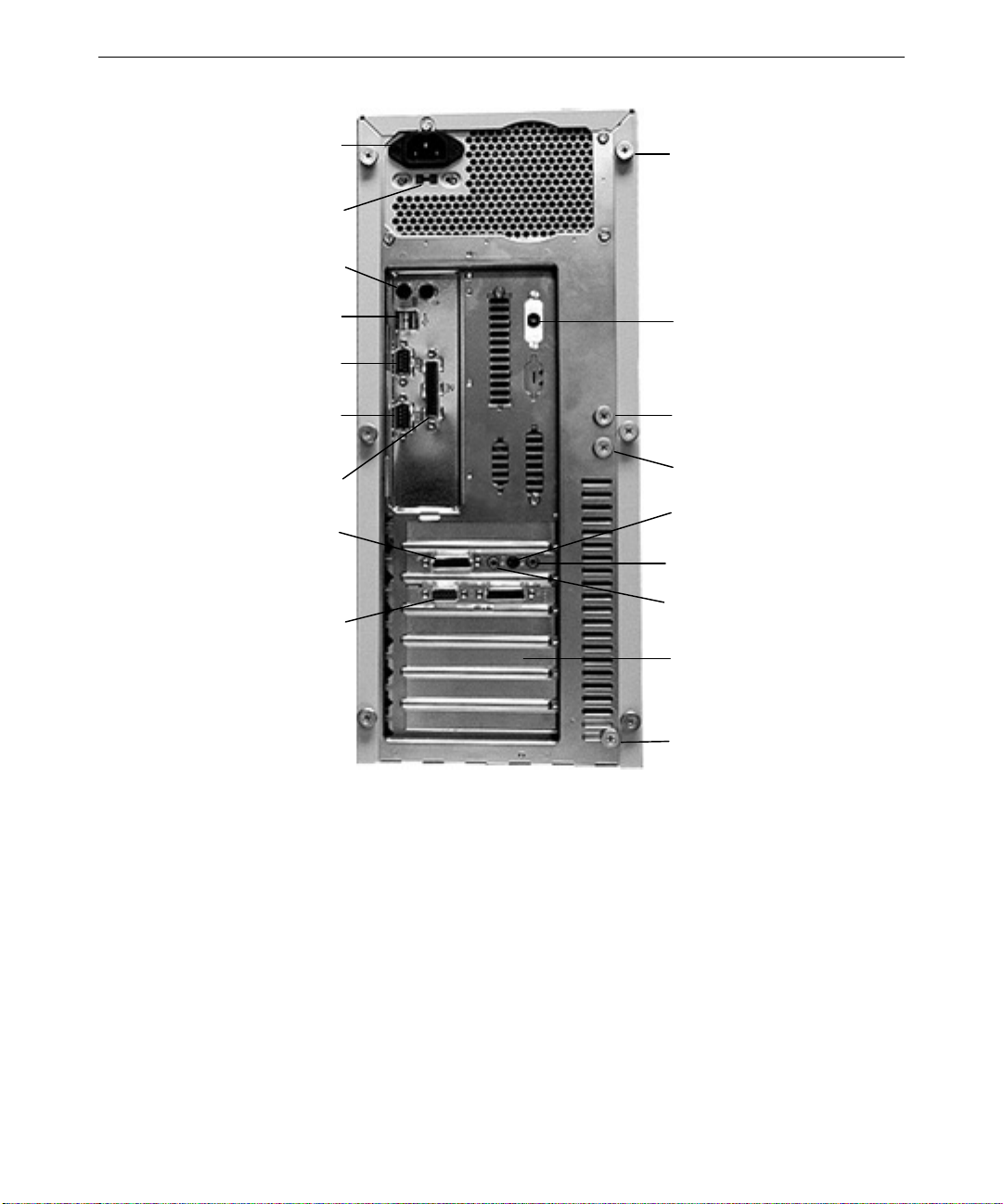
Connecting Peripheral Cables
Connect the following cables to the ports on the back panel of the base unit.
u
Mouse cable to mouse port (PS/2 type)
u
Keyboard cable to keyboard port (PS/2 type)
u
Speaker power cable to keyboard/speaker power port (on a system with optional
speakers)
u
Speaker cable to speaker port (on a system with optional speakers)
u
Microphone cable to microphone port (on a system with an optional microphone)
u
Video cable from monitor to video port
u
Network cable to network port (on the optional network adapter)
u
Telephone wire to telephone jack (on the optional modem)
See the following figure and the expansion card documentation, if necessary.
All ports and cables are keyed or molded to make connecting the cables easy. If you find it
difficult to connect a cable, make sure that you are aligning the cable connector correctly
with the port.
3
CAUTION If you do not use Intergraph cables, ensure the cables you use are shielded to prevent
excessive electromagnetic interference (EMI). Intergraph cables are designed to reduce the
amount of EMI produced by the system.
Connecting Powered Speakers
If you purchased a multimedia option with powered speakers for your system, see the
following instructions when connecting the speakers to the system.
To connect powered speakers to the system:
1. Locate the 6-foot black power cable (packaged separately from the speakers). The cable
has identical connectors on each end.
2. Connect one end of the power cable to the keyboard/speaker power port on the back of
the base unit. See the following figure to locate the keyboard/speaker power port.
3. Connect the other end of the power cable to the DC power port on one of the speakers.
See the documentation delivered with the speakers for more information.
4. Connect the audio cable from the speaker to the Line Out port on the back of the base
unit. See the following figure to locate the keyboard/speaker power port.
Page 18

4
Connecting a Multimedia Keyboard to a TD-220
If you purchased a multimedia option with a multimedia keyboard for your TD-220 system,
see the following instructions when connecting the keyboard to the system.
To connect a multimedia keyboard to a TD-220:
1. Locate the 6-inch black power cable (packaged separately from the keyboard). The
cable has different connectors on each end.
2. Disconnect the keyboard’s power cable from the “Y” adapter cable to which it is already
connected. See the keyboard User’s Manual to ensure you disconnect the proper cable.
3. Connect the 6-inch black power cable to the keyboard’s power cable, and then to the
keyboard/speaker power port on the back of the base unit. The cable is keyed for proper
connection. See the following figure to locate the keyboard/speaker power port.
NOTE This leaves one “branch” of the “Y” adapter cable disconnected. Do not try to connect this
“branch” to any other ports on the back of the base unit.
4. Connect the single connector of the “Y” adapter cable to the appropriate port on the
back of the base unit, as directed in the keyboard User’s Manual.
5. Connect the microphone and line out cables to the appropriate ports on the back of the
base unit, as directed in the keyboard User’s Manual.
Connecting a Microphone
The microphone jack on the Ensoniq AudioPCI sound card is a 1/8-inch jack that accepts
mono input. It can be used as a source for digital recording, a source to be mixed with the
overall output signal, or both.
You can locate the Mic BIAS setting on the Microphone panel of the Ensoniq Mixer in
Windows NT 4.0 and on the Settings tab of the Windows 95 driver. If desired, apply a 30dB gain to the microphone input by checking the Boost box in the Microphone panel of the
Ensoniq Mixer.
NOTE You should disable the BIAS power if you use a dynamic microphone. Distortion may occur
if BIAS power is enabled with some dynamic microphones.
Page 19
5
AC Power
Connector
AC Voltage Switch
115/230 V
Mouse (right)
Keyboard (left)
USB Ports
Serial Port COM1
Serial Port COM2
Parallel Port LPT1
Game/MIDI
Video Out
Tool-less Entry
Cover S c re w
(one of six)
Keyboard/Speaker
Power Port
EMI Shield Screw
(one of two)
Fan Bracket Screw
Line In
Line Out
Microphone
Expansion Board
Slots
EMI Shield Screw
(two of two)
Connecting to AC Power
WARNING If you do not set the AC voltage switch correctly, serious equipment damage may
result when you turn on power to the system.
To connect the system to AC power:
1. Make sure that the AC voltage switch on the back panel of the base unit is set to the
proper line voltage for your location. If your location uses 115 volts, make sure the
number 115 is visible on the switch. If your location uses 230 volts, make sure the
number 230 is visible on the switch. See the previous figure.
2. Connect the power cord to the AC Power connector on the back panel of the base unit,
and then to a three-prong, grounded AC wall outlet. See the previous figure.
Page 20

6
Expansion Card Arrangement
Expansion cards are installed in the Peripheral Component Interconnect (PCI) and Industry
Standard Architecture (ISA) expansion slots in the base unit. If you purchased any
expansion cards from Intergraph Computer Systems, they are installed in specific slots as
follows.
TD-22, TD-25, TD-220
Slot Type Expansion Card
1 (Top) PCI Sound card or SCSI adapter (optional)
2 PCI Sound card or video display adapter (optional; for dual-screen)
3 PCI Video display adapter
4 PCI or ISA Network adapter (optional)
5 ISA 6 ISA PC Card adapter (optional; no external connection)
7 (Bottom) ISA Modem
TD-225
Slot Type Expansion Card
1 (Top) PCI Sound card or SCSI adapter (optional)
2 PCI Sound card or video display adapter (optional; for dual-screen)
3 PCI Video display adapter
4 PCI 5 PCI or ISA Network adapter (optional)
6 ISA PC Card adapter (optional; no external connection)
7 (Bottom) ISA Modem
Starting the System
To turn on power to the system, press the power switches on the base unit and the monitor.
See the following figure.
The system starts, and boots to a Setup screen or logon dialog for the operating system. If
you are setting up the system for the first time, an End-User License Agreement (EULA)
displays.
Page 21
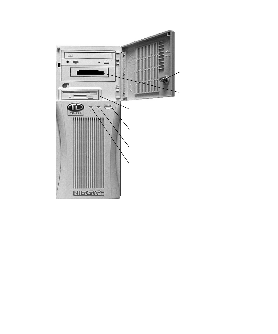
Floppy Disk Drive
Power Switch
Power On LED
7
CD-ROM
Drive
Door Lock
PC Card Slot
What’s Next?
See Chapter 2, “Setting Up the Software,” for instructions on setting up the operating system
and associated system software.
Disk Access LED
Page 22

8
Page 23

2 Setting Up the Software
Follow the instructions in this chapter to set up the operating system and associated system
software on your Intergraph Computer Systems TD-2x or TD-22x system.
Preparing for Operating System Setup ............................................................................... 10
Going Through Operating System Setup ............................................................................ 12
Finishing System Setup...................................................................................................... 13
Creating a Repair Disk ......................................................................................... 13
Creating System Software Backup Diskettes......................................................... 14
What’s Next?..................................................................................................................... 14
9
Page 24

10
Preparing for Operating System Setup
Your system is equipped with a partitioned and formatted internal hard disk drive. Any
additional disk drives delivered with the system must be partitioned and formatted before you
can use them. See the operating system documentation and Help for information on
partitioning and formatting disk drives.
The operating system and associated system software is pre-installed on the primary hard
disk drive. Intergraph Computer Systems installed the following system software:
u
Driver software for the mouse
u
Driver software for the installed sound card
u
Driver software for the installed video display adapter
u
Driver software for the installed SCSI adapter (optional)
u
Driver software for the installed networking adapter (optional)
u
Operating system network software (TCP/IP and NetBEUI; optional)
u
Quick-Fix Engineering (QFE) update software -- fixes for operating system problems or
limitations (if any are needed)
u
InterSite software
u
The default File Allocation Table (FAT) file system
You must follow the operating system Setup process to prepare Microsoft Windows NT or
Microsoft Windows 95 for use. Before you go through Setup, have the following documents
available:
u
Microsoft’s Start Here (for Windows NT) or Welcome to Windows 95.
u
Documents delivered with any expansion cards or additional peripheral devices
purchased from Intergraph Computer Systems
Page 25

Get and record the following information:
u
Your name, and the name of your
company or organization:
u
For a system running Windows NT,
the CD Key from the Windows NT CD
case, or the Product ID Number from
Start Here or the registration card:
u
For a system running Windows 95, the
Product ID Number from Welcome to
Windows 95 or the registration card:
u
A username for setting up a user
account:
If the system is connected to a network, get and record the following information from your
network administrator:
u
Computer name for your system:
u
Workgroup name (if the system will be
part of a workgroup):
11
u
Domain name (if the system will be
part of a Windows NT domain):
If the system is connected to a network that uses the Transmission Control Protocol/Internet
Protocol (TCP/IP), get and record the following TCP/IP networking information from your
network administrator:
u
Internet Protocol (IP) address for your
system:
u
IP subnet mask for your system:
u
IP domain name for your network:
u
IP address for your network’s default
gateway:
u
IP addresses for your network’s
Domain Name System (DNS) servers,
if any:
u
IP addresses for your network’s
Windows Internet Name Service
(WINS) servers, if any:
Page 26

12
Have several blank, formatted diskettes available to create backup diskettes containing
system software.
The Windows NT delivery media contain software and drivers for both Reduced Instruction
Set Computing (RISC)- and Intel-based systems. When installing Windows NT distribution
files, make sure to install them from the \i
386 directory (the Intel software directory) on the
delivery media. For example, if you are installing a device driver from the Windows NT
CD-ROM, key in the following when asked for the path to the file, where drive is the drive
letter for the CD-ROM drive:
386
drive:\i
Going Through Operating System Setup
The first time you start the system, it boots to an End-User License Agreement screen. After
reviewing and accepting the terms of the agreement, follow the instructions to continue
operating system Setup. Take the default settings provided by Setup, except as noted in the
following text. You can set up a user account and join a workgroup or domain after you
configure the video display, the sound processor, and networking.
On a system running Windows NT or Windows 95:
u
Allow Setup to configure the network only if the system has an installed network
adapter, and only if the system is connected to the network.
u
When prompted to create an Emergency Repair Disk (Windows NT) or a Startup
diskette (Windows 95), do so.
u
If you do not set up a user account during Setup, press ENTER or select OK at the logon
dialog to log on to the operating system.
On a system running Windows NT:
u
On a system shipped from the factory without a CD-ROM drive, the system’s hard disk
drive contains Windows NT Setup files in the
network or video display adapter drivers, you can see the i
for the location of Windows NT Setup files. If you delete the i
C:\i386 directory. When installing
386 directory when prompted
386 directory from the
system’s hard disk, you must have access to a Windows NT CD-ROM to use Windows
NT Setup files.
On a system running Windows 95:
u
While Windows 95 files are being copied to the system, you are prompted for the
Windows 95 Setup boot diskette. This occurs even if the Windows 95 Setup boot
diskette is already inserted in the floppy disk drive. Select OK to continue.
Page 27

Next, you are notified that a CD-ROM driver file (such as MTMCDAI.SYS or
TAISATAP.SYS) could not be found on the windows 95 setup boot diskette. In the dialog
that displays, specify that the file should be copied from a:\, and then select OK.
u
The system’s hard disk drive contains Windows 95 Setup files in the
C:\WINDOWS\OPTIONS\CABS directory, as compressed .CAB files. When installing
network or video display adapter drivers, you can see the
for the location of Windows 95 Setup files. If you delete the
system’s hard disk, you must have access to a Windows 95 CD-ROM to use Windows 95
Setup files.
For more information on operating system Setup, and on using the interface features of the
operating system, see the operating system documentation and Help.
Finishing System Setup
After operating system Setup is completed, an InterSite Welcome icon (“Press to finish
setup”) displays on the operating system desktop. Double-click this icon, or select
Programs/InterSite/Welcome from the Start menu, to display InterSite Welcome.
13
CABS directory when prompted
CABS directory from the
InterSite Welcome helps you do the following:
u
Create a repair disk for the operating system.
u
Create backup diskettes of device driver software and other system software products.
u
Display an online System Introduction for your system.
u
Learn about Intergraph Computer Systems customer support.
You should take advantage of the tools provided by InterSite Welcome to ensure that your
system is fully ready for use. See InterSite Welcome for more information. Also see the
following sections for information on creating a repair disk and creating backup diskettes.
Creating a Repair Disk
If you did not create an Emergency Repair Disk (Windows NT) or a Startup diskette
(Windows 95) during Setup, use the tools provided by InterSite Welcome to do so. The files
on these diskettes can restore the original contents of a damaged operating system Registry
(that is, at the time the operating system was installed), along with the standard operating
system drivers. You should also update an Emergency Repair Disk or a Startup diskette after
you finish configuring the system.
See the operating system documentation and Help for information on creating an Emergency
Repair Disk or a Startup diskette.
Page 28

14
Creating System Software Backup Diskettes
Backup diskettes for some device driver software and system software products are not
delivered with the system. Use InterSite Version Manager, available through InterSite
Welcome, to create system software backup diskettes.
Version Manager lets you create backup diskettes containing device driver software and
system software products that were installed on the system before shipment, and which are
not available on the operating system CD-ROM. You may need these backup diskettes later
-- for example, if you have to reinstall a device driver or the operating system.
WARNING You must create system software backup diskettes after you set up the system
hardware and complete the operating system Setup program. If you do not do this,
you may not be able to reinstall critical system software or the operating system if
needed.
NOTE You may not have to create backup diskettes for all system software. If Version Manager
does not list drivers or other system software products, they are available on the operating
system software CD-ROM or on backup diskettes delivered with expansion cards.
If the system requires Quick-Fix Engineering (QFE) update software, it is included in the
system software available for backup diskette creation. QFE update software contains fixes
for operating system problems or limitations, and is only shipped with the system if it is
needed. If QFE update software is shipped with the system, you should create a QFE backup
diskette for use if you have to reinstall the operating system.
See Version Manager Help for information on creating system software backup diskettes.
Visit the Intergraph Computer Systems site on the World Wide Web and vendor bulletin
boards for new and updated drivers.
What’s Next?
See the online System Introduction for information on system features and controls.
See Chapter 3, “Configuring the System,” to configure the system for use.
Page 29

3 Configuring the System
Follow the instructions in this chapter to configure your Intergraph Computer Systems
TD-2x or TD-22x system for use.
Configuring the Video Display........................................................................................... 16
Correcting Video Display Problems...................................................................... 17
Configuring Networking.................................................................................................... 18
Configuring the Sound Processor....................................................................................... 18
Configuring a CD-Recorder Drive ..................................................................................... 19
Configuring a PC Card Adapter ......................................................................................... 19
Configuring a Modem........................................................................................................ 20
Configuring a Tape Drive .................................................................................................. 20
Configuring a Zip Drive..................................................................................................... 20
Configuring External SCSI Peripherals .............................................................................. 21
Updating the Operating System.......................................................................................... 21
Configuring the BIOS........................................................................................................ 22
SCSI System BIOS............................................................................................... 22
Updating the BIOS ............................................................................................................ 23
TD-22, TD-25 BIOS ............................................................................................ 23
TD-220 BIOS....................................................................................................... 24
TD-225 BIOS....................................................................................................... 25
What’s Next?..................................................................................................................... 27
15
Page 30

16
Configuring the Video Display
Your system shipped with the video display driver set to display at a resolution of 1024 x
768. If you want to change the video display to another resolution, be sure your monitor can
support the desired resolution.
To change the video display resolution:
1. Right-click the operating system desktop and select Properties. The Display Properties
dialog displays.
2. Select a resolution appropriate for your system’s monitor.
3. On Windows NT systems, click Test to test the new video mode.
4. Click OK, then restart the system.
If the monitor connected to your system does not support a resolution of 1024 x 768, you can
reset the video display to another resolution.
To reset the video display resolution on a system running Windows NT:
1. Restart the system.
2. At the boot screen, select the VGA mode option for Windows NT.
3. When the system has started, log on to Windows NT.
4. Right-click the desktop and select Properties. The Display Properties dialog displays.
5. Select a resolution appropriate for your system's monitor.
6. Click Test to test the new video mode, and then click OK.
7. Restart the system.
To reset the video display resolution on a system running Windows 95:
1. Restart the system.
2. When Starting Windows 95 displays, press
displays.
3. Select the Safe Mode option, and then press
standard VGA resolution (640 x 480).
4. Right-click the desktop and select Properties. The Display Properties dialog displays.
5. Select a resolution appropriate for your system's monitor, and then click OK.
6. Restart the system.
F8. The Windows 95 Startup Menu
ENTER. The system boots, using the
Page 31

See the documentation and README.TXT files accompanying the installed video adapter and
driver for detailed configuration instructions. For information on using the Display
Properties or Display Settings dialog, see the operating system documentation and Help.
Correcting Video Display Problems
If the system’s video display is black, not synchronized, or distorted after you restart the
system, you may have a video configuration problem.
On a system running Windows NT, use the Last Known Good option to return the system to
the last known good configuration recorded by Windows NT.
To use the Windows NT Last Known Good option:
1. Power down and restart the system.
2. Press the space bar at the following prompt:
Press space bar NOW to invoke the Last Known Good Menu
If the Last Known Good option fails, or if Windows 95 is installed, restart the system in
VGA mode to correct the video configuration problem.
17
To restart the system in VGA mode:
1. Power down and restart the system.
2. On systems running Windows NT, select the Windows NT Workstation 4.00
[VGA mode] option at the boot screen.
On systems running Windows 95, press the
F8 key when Starting Windows 95...
displays on the screen, then select Safe Mode.
When the operating system desktop displays, right-click the desktop background and select
Properties. The Display Properties dialog displays. Check for the following common
configuration problems and solutions.
u
A multi-sync monitor is connected to the system, but a multi-sync monitor type is not
selected, and the display driver cannot determine this by querying the monitor. Select
an appropriate multi-sync monitor type.
u
A selected resolution, depth, or refresh rate is not supported by the multi-sync monitor.
Try using different video display settings.
u
The Dual Screen option is selected, but only one video card is detected. Clear the Dual
Screen option.
Page 32

18
u
A multi-sync monitor is selected, but a monitor with different video timings (such as an
Intergraph InterVue monitor) is connected to the system. Select the appropriate monitor
type as described previously.
u
The monitor selection doesn’t match the multi-sync monitor attached to the system.
Restart the system in VGA mode, then select a new monitor as described previously.
u
A graphics resolution and color depth has been selected that exceeds installed display
memory. Restart the system in VGA mode, then open Display in the Control Panel to
reinstall and configure the display driver as described in the video display adapter
documentation delivered with the system.
After you’ve configured the video display, restart the system and select the non-VGA version
of the appropriate operating system to use the new configuration.
If problems persist, contact the Customer Response Center for help.
Configuring Networking
If you purchased a network adapter with your system, it was installed before shipment. You
must configure the operating system to use the network adapter. To do this, you may have to
install network driver software and network adapter control software, and then change
operating system settings to enable networking. Before you configure networking, make sure
that the system has an installed network adapter, and that the network adapter is connected
to a network.
To configure networking, open Network in the Control Panel. Follow the instructions in the
dialogs to set up the system to use a network. Be sure to set up the appropriate network
protocols, such as TCP/IP and NetBEUI, for the network you are connecting to.
See the documentation for the installed network adapter for detailed configuration
instructions. See the operating system documentation and Help for information on setting up
the system to use a network.
Configuring the Sound Processor
If you purchased an Ensoniq sound card with your system, the sound processor was
configured before shipment. If the system has a multimedia keyboard or a microphone and
speakers, you can use either the operating system’s or Ensoniq’s sound control programs to
control them.
Page 33

For information on using the sound control programs, see the online documentation on the
Ensoniq CD-ROM (accompanying the sound card), the operating system documentation, or
Help.
Configuring a CD-Recorder Drive
If you purchased a CD-Recorder (CD-R) drive with your system, it was installed before
shipment. If you purchased the CD-R drive in place of the standard CD-ROM drive, the
driver software enabling it to be used as a standard CD-ROM drive was installed before
shipment. To use the CD-R drive to record CDs, you must install the CD-R driver software
and any associated application software programs.
See the documentation delivered with the CD-R drive for detailed software installation and
configuration instructions.
Configuring a PC Card Adapter
If you purchased a PC Card adapter with your system, it was installed before shipment. To
use the PC Card adapter, you may have to install the driver software and any associated
application software programs.
19
You may have received a diskette titled CardWizard for Windows NT. This diskette contains
the latest Windows NT 4.0 driver and CardWizard software for the PC Card adapter. You
must install this software on the system to ensure the adapter works correctly with Windows
NT 4.0
u
If you received this diskette, install the software from the diskette after setting up the
system hardware and completing the operating system Setup. See the
README.TXT file
and the CardWizard for Windows NT User’s Guide delivered on the diskette for
installation instructions.
u
If you did not receive this diskette, the latest driver and CardWizard software is already
installed on the system. You can make a backup diskette for this software using
InterSite Version Manager. See Version Manager Help for more information on
creating system software backup diskettes.
NOTE If you reinstall Windows NT 4.0 Service Pack 3 software on a TD-22 or TD-25 with a PC Card
adapter, you must install the CardWizard software after installing Service Pack 3 software. If
you do not do this, you may experience problems when using the PC Card adapter. This is
an exception to the general rule that you must reinstall Service Pack 3 software any time you
change hardware or software components on a system.
Page 34

20
Depending on your system’s configuration, you may have to reserve an interrupt request
(IRQ) for a PC Card device inserted in the PC Card adapter. If the CardWizard software
reports that the driver for the PC Card device failed to start, you should reserve an IRQ for
that PC Card device. The CardWizard will display the IRQ that you should reserve. See the
System Board Manual for information on reserving IRQs in your system’s BIOS.See the
documentation delivered with the PC Card adapter for detailed software installation and
configuration instructions.
Configuring a Modem
If you purchased an internal modem with your system, it was installed before shipment. To
use the modem, you may have to install the driver software and any associated applications
software programs. You may also have to change operating system settings to enable the
system to use the modem.
See the documentation delivered with the modem for configuration instructions. See the
operating system documentation and Help for information on using a modem with the
system.
Configuring a Tape Drive
If you purchased an internal tape drive with your system, it was installed before shipment.
On a system running Windows 95, you may have to install the driver software and any
associated applications software programs to use the tape drive. On a system running
Windows NT, you can use the Windows NT Backup tool to run the tape drive; select
Programs/Administrative Tools/Backup from the Start menu.
See the documentation delivered with the tape drive for configuration instructions. See the
device documentation, operating system documentation, and Help for information on using
the tape drive.
Configuring a Zip Drive
If you purchased an internal Zip drive with your system, it was installed before shipment. To
use the Zip drive, you may have to install the driver software and any associated applications
software programs.
See the documentation delivered with the Zip drive for configuration instructions. See the
device documentation, operating system documentation, and Help for information on using
the Zip drive.
Page 35

Configuring External SCSI Peripherals
The optional SCSI adapter is designed to support Ultra SCSI (also known as SCSI-3)
devices. If you connect SCSI-1 or SCSI-2 devices to the adapter, data transfer rates are
limited to the device’s speed.
CAUTION Using a non-compliant SCSI-1 device with your system may cause your system to stop
working, or lead to other unpredictable results.
You can connect up to seven external single-ended SCSI devices to an installed SCSI
adapter. The total length of the external SCSI cables depends on the number of devices
connected to the SCSI adapter. The total length must not exceed the following:
21
Devices
1 to 4 6 meters 3 meters 3 meters
5 to 8 3 meters 3 meters 1.5 meters
NOTE You must count the SCSI adapter as one device.
When calculating the total length of the SCSI cables connected to the SCSI adapter, use the
following estimates where appropriate:
SCSI cabling inside each external device 203.2 mm
NOTE Make sure the last device on a chain of external SCSI devices has an active SCSI terminator
attached to the open SCSI port. All other external devices must have SCSI termination
disabled or removed.
See Chapter 6, “Expanding the System,” for information on connecting external SCSI
devices to the system.
SCSI-1 SCSI-2 SCSI-3
Updating the Operating System
Microsoft Service Packs contain the latest improvements and system fixes for Microsoft
operating systems. Service Packs are created by Microsoft for post-release support. You can
obtain Service Packs from Microsoft’s World Wide Web and FTP sites free of charge.
CAUTION If Intergraph provides a Service Pack through the IBBS or with a product or system, it has
been certified against Intergraph hardware as described in the announcement of its
availability. If you obtain a Service Pack from any other source, be aware that it may not be
certified against your Intergraph hardware.
Page 36

22
Configuring the BIOS
Your system’s Basic Input/Output System (BIOS) records basic system operating parameters,
such as the boot sequence, hard drive settings, and the type of video display. The system’s
operating parameters are set in the BIOS before shipment, and you should not need to
change them immediately. However, you may want to configure some aspects of system
operation later by changing BIOS settings.
The BIOS is stored in flash Erasable-Programmable Memory (EPROM) on the system board,
and reads the system parameters in the system’s Complementary Metal-Oxide
Semiconductor (CMOS) Random-Access Memory (RAM). When you turn off power to the
system, a battery provides power to CMOS RAM, which retains the system parameters.
Each time you turn on system power, the BIOS uses the stored parameters to configure the
system.
To run the BIOS Setup program:
1. Restart the system.
2. When the BIOS version displays on the screen:
−
On a TD-22 or TD-25, press
− On a TD-220, press F1
− On a TD-225, press DEL
The System Board Manual provides detailed information on the BIOS, including instructions
for running the BIOS Setup program to change BIOS parameter settings, and a list of
available BIOS parameters and their default settings.
SCSI Sy stem BIOS
On a system equipped with a SCSI adapter and internal SCSI hard disk drives, the BIOS is
configured to boot from and use the SCSI disk drives. If you update the BIOS or reset the
BIOS configuration, make sure the appropriate BIOS parameters are set correctly for a SCSI
system.
TD-22, TD-25 BIOS
The BIOS automatically detects the SCSI drives.
F2
Page 37

TD-220 BIOS
If you have a version of the BIOS previous to 01.00.11.CS1, do the following in BIOS Setup:
u
On the Advanced/Plug and Play Configuration screen, set Configuration
Mode to Use ICU.
u
On the Advanced/Plug and Play Configuration screen, set Boot with PnP
OS to None.
u
On the Advanced/Peripheral Configuration screen, set Secondary IDE
Interface to Disabled.
TD-225 BIOS
Do the following in the Advanced Setup menu in BIOS Setup:
u
Set the 1st Boot Device to be the floppy disk drive.
u
Set the 2nd Boot Device to be the SCSI disk drive.
Updating the BIOS
23
From time to time, new versions of the system’s BIOS are made available on the IBBS. You
may want to update the system’s current BIOS with a new version to take advantage of fixes
or enhancements.
TD-22, TD-25 BIOS
To update the TD-22 or TD-25 BIOS:
1. Record the BIOS parameter settings for your system. To do this, restart the system, and
F7 during boot to run BIOS Setup. Write down the setting for each parameter;
press
then exit from BIOS Setup and let the system continue to boot.
2. From the IBBS login, go to Intergraph Product Centers, Systems and Networking, File
Libraries, and Delivered Drivers; select the operating system and hardware platform.
3. Find the
4. Use an unzip utility to open the
5. Insert a diskette into the floppy disk drive.
6. In the directory containing the
creates a boot diskette with the new BIOS file and the BIOS flash programming utility.
7. After the
restart the system.
FLASHPROG product and download it to a directory on your system.
INSTALL.BAT program completes, leave the diskette in the floppy disk drive and
FLASHPROG product and extract the files from it.
FLASHPROG files, run the INSTALL.BAT program. This
Page 38

24
8. At the MS-DOS command prompt, run PHLASH.EXE to update the current BIOS. For
example, if the BIOS file on the boot diskette is named
TX-I06.ROM, you would key in
the following command to update the BIOS:
phlash tx_i06.rom
9. After the BIOS is updated, the system shuts down. Remove the diskette from the floppy
disk drive and label it BIOS Update date, where date is today’s date.
10. Turn on power to the system.
As the system boots, press
PhoenixBIOS Version 4.0 Release 6.0 430TX-I006
BIOS Setup starts.
11. Make sure that all parameter settings match the settings you recorded before you
updated the BIOS. In particular, verify that on both the Main/Primary Master and
Main/Primary Slave screens, both LBA Mode Control and 32 Bit I/O are set to
Enabled.
12. Save and exit from BIOS Setup.
13. Restart the system.
For more information on the phlash command, type phlash /? at the command prompt. For
more information on updating the BIOS, see the
FLASHPROG product.
TD-220 BIOS
To update the TD-220 BIOS:
1. Record the BIOS parameter settings for your system. To do this, restart the system, and
press
then exit from BIOS Setup and let the system continue to boot.
2. From the IBBS login, go to Intergraph Product Centers, Systems and Networking, File
Libraries, and Delivered Drivers; select the operating system and hardware platform.
F2 when you see a message like the following:
README.TXT file delivered with the
F1 during boot to run BIOS Setup. Write down the setting for each parameter;
3. Find the
4. Use an unzip utility to open the
FLASHPROG product and download it to a directory on your system.
FLASHPROG product and extract the files from it.
5. Insert a diskette into the floppy disk drive.
6. In the directory containing the
FLASHPROG files, run the INSTALL.BAT program. This
creates a boot diskette with the new BIOS file and the BIOS flash programming utility.
7. After the
INSTALL.BAT program completes, leave the diskette in the floppy disk drive and
restart the system.
Page 39

8. When prompted, press ENTER to go to the main menu.
9. If you want to save the current BIOS, select Save Flash Memory Area To a File and
ENTER. Otherwise, go to step 15.
press
10. Insert an empty, formatted diskette into the floppy disk drive.
25
11. Select Save System BIOS and press
12. When prompted to enter a path to the file, type a:\save.bio and press
13. When prompted to enter the Flash Data Image title, type save and press
14. From the main menu, select Update Flash Memory From a File and press
15. Select Update System BIOS and press
16. When prompted to enter a path to the file, press
the up/down arrow keys to select drive [-A-], and then press
the BIOS version (for example, 1011CS1_.BIO), and then press
17. When prompted that the BIOS is about to be changed, press
ENTER.
ENTER.
ENTER.
ENTER.
ENTER.
TAB to select the Directories box. Press
ENTER. Press TAB to select
ENTER.
ENTER.
18. After the BIOS has been successfully updated, remove the diskette from the floppy disk
drive. Label the diskette BIOS Update date and Previous BIOS filename, where date is
today’s date and filename is the filename you entered in step 12 above
19. Press
ENTER to restart the system. As the system boots, turn off power to the system;
then turn on power to the system again.
20. As the system boots, make sure that the BIOS version displayed is the new version; then
DELETE to enter BIOS Setup.
press
21. In BIOS Setup, press
F5 to return the BIOS parameters to their default settings. If you
do not do this, the system may not function correctly with the new BIOS.
22. Reenter the parameter settings you recorded before you updated the BIOS.
23. After reentering the parameter settings, make sure that they match the settings you
recorded before you updated the BIOS.
24. Save and exit from BIOS Setup.
25. Restart the system.
If the system experiences operational problems after you restart it, reprogram the BIOS using
the previous version of the BIOS that you saved to diskette.
Page 40

26
TD-225 BIOS
To update the TD-225 BIOS:
1. Record the BIOS parameter settings for your system. To do this, restart the system, and
press the
parameter, then exit from BIOS Setup and let the system continue to boot.
2. From the IBBS login, go to Intergraph Product Centers, Systems and Networking, File
Libraries, and Delivered Drivers; select the operating system and hardware platform.
DELETE key during boot to run BIOS Setup. Write down the setting for each
3. Find the
4. Use an unzip utility to open the
FLASHTD225 product and download it to a directory on your system.
FLASHTD225 product and extract the files from it.
5. Insert a blank, formatted diskette into the floppy disk drive.
6. In the directory containing the
FLASHTD225 files, run the INSTALL.BAT program. This
creates a boot diskette with the new BIOS file and the BIOS flash programming utility.
7. After the
INSTALL.BAT program completes, leave the diskette in the floppy disk drive and
restart the system.
8. At the MS-DOS command prompt, run
example, if the BIOS file on the boot diskette is named
AMIFLASH to update the current BIOS. For
AMIBOOT.ROM, key in the
following command to update the BIOS:
amiflash amiboot.rom
9. After the BIOS is updated, you are prompted to press a key to restart the system.
Remove the diskette from the floppy disk drive and label it BIOS Update date, where
date is today’s date.
Press a key to restart the system. As the system boots, press
F1 when you see a message
like the following:
CMOS settings are corrupt
Press <F1> to continue.
10. Make sure that all parameter settings match the settings you recorded before you
updated the BIOS. In particular, verify that on both the Main/Primary Master and
Main/Primary Slave screens, both LBA Mode Control and 32 Bit I/O are set to
Enabled.
Page 41

What’s Next?
See Chapter 4, “Operating Notes,” to learn things you may need to know when operating the
system.
See Chapter 5, “Installing System Software,” if you need to reinstall the operating system
and associated system software for any reason.
See Chapter 6, “Expanding the System,” for information on expanding the system.
27
Page 42

28
Page 43

4 Operating Notes
Use the information in this chapter when operating your Intergraph Computer Systems
TD-2x or TD-22x system.
Starting and Shutting Down the System ............................................................................. 30
Starting MS-DOS from the Startup Menu (Windows 95) ................................................... 31
Observing Operating Precautions....................................................................................... 31
Updating an Emergency Repair Disk or a Startup Diskette................................................. 32
Using InterSite Programs (Windows NT)........................................................................... 32
Accessing the Audio System Mixer.................................................................................... 33
Ensuring PC Card Support and Operation .......................................................................... 34
Booting from an External SCSI Disk Drive........................................................................ 34
29
Page 44

30
Starting and Shutting Down the System
After you complete Setup and start the system for the first time, you can start and stop the
system as needed.
To start the operating system:
1. Turn on power to the system.
2. On a system running Windows 95, the operating system starts.
On a system running Windows NT Workstation 4.0, the boot menu displays; select
Windows NT to display the logon dialog.
To log on to the operating system:
1. If the logon dialog does not display, press
2. Type a username and password into the appropriate boxes.
3. If appropriate, type a domain name.
4. Select OK or press
To log off, restart, or shut down the operating system:
1. Select Shut Down from the Start menu.
2. Perform one of the following steps, as appropriate:
−
To log off the operating system, select the “close all programs” option (if
given), and then select OK.
−
To restart the system, select the restart option, and then select OK.
−
To shut down the system, select the shutdown option, and then select OK.
After shutting down or logging off the operating system, you can turn off the power to the
base unit and monitor.
For more information on starting and stopping the operating system, see the operating
system documentation and Help.
ENTER.
CTRL+ALT+DELETE to display it.
Page 45

31
Starting MS-DOS from the Startup Menu (Window s
95)
You can start the system in MS-DOS from the Windows 95 Startup menu. If you do this, the
drivers for the CD-ROM drive and the mouse do not load automatically. To enable use of
the CD-ROM drive and the mouse in MS-DOS, you must load their drivers manually after
the system starts in MS-DOS.
To start the system in MS-DOS from the Windows 95 Start menu:
1. Restart the system.
2. When the message Starting Windows 95 displays, press
F8. The Windows 95
Startup Menu displays.
3. Select the Command Prompt option, and then press
ENTER.
To load the CD-ROM drive and mouse drivers in MS-DOS:
At the MS-DOS command prompt, key in windows\dosstart.bat. This runs
DOSSTART.BAT,
which loads the drivers for the CD-ROM drive and the mouse.
NOTE You need not run DOSSTART.BAT if you put the system into MS-DOS mode from within
Windows 95.
Observing Operating Precautions
Observe the following precautions when operating the system:
u
When restarting the system, use the operating system controls instead of turning the
power switch off and on. Use the power switch only when instructed, or as the last
alternative for restarting the system.
u
Never turn off power to the base unit when the disk access LED is lit.
u
After turning off power to the base unit, wait at least 30 seconds before turning the
power on again, to ensure that the disk drives have stopped and the system has powercycled properly.
u
Run virus scan software periodically to ensure that your system’s files and programs are
not corrupted.
Page 46

32
Updating an Emergency Repair Disk or a Startup Diskette
You may have created an Emergency Repair Disk (Windows NT) or a Startup diskette
(Windows 95) during first-time startup, or through InterSite Welcome. If you did not, you
should create the appropriate diskette after you finish configuring the system. If you did, you
should update it any time you change the configuration of the system. The files on the
Windows NT Emergency Repair Disk can restore the original contents of a damaged
operating system Registry (that is, at the time the operating system was installed), along with
the standard operating system drivers. Use the Startup diskette to start the system in the
event you have trouble starting Windows 95.
See the operating system documentation for information on creating an Emergency Repair
Disk or a Startup diskette.
Using InterSite Programs (Windows NT)
TD-2x and TD-22x systems running Windows NT ship with the following InterSite
programs:
u
InterSite Version Manager is a tool for creating system software backup diskettes, and
for updating device drivers and other system software products installed on the system.
u
InterSite Hardware Monitor is an easy-to-use interface to instrumentation data measured
by sensors inside the computer. Event information is reported to the Windows NT
Event Log and displayed graphically. For example, temperatures inside the system
chassis display on color-coded temperature scales.
u
InterSite DMI Console gives easy access to the system’s status and configuration
information. The Console is based on the Desktop Management Interface (DMI),
through a window containing a graphical information tree view pane, a service provider
component information pane, and a message pane. DMI Console works with the
Desktop Management Interface (DMI), a technology standard that enables the effective
management of personal computers (Pcs).
u
InterSite Watchdog is a system monitoring tool with remote monitoring capabilities.
You can install Watchdog on a system running the Windows NT, and use it to monitor
workstations and servers also running Windows NT.
From the operating system Start menu, go to Programs/InterSite to find the InterSite
programs on your system. See the online Help for each InterSite program for more
information on how to use the program.
Page 47

Accessing the Audio System Mixer
On systems shipped from the factory with a system audio option, you have quick access to
the audio system’s Mixer program. The Mixer program replaces the default operating
system Volume Control program.
To display the audio system’s Mixer program, do one of the following:
u
Click the speaker icon on the operating system taskbar.
u
From the Start menu, select Programs/Accessories/Multimedia/Volume Control.
If you reinstall the operating system, or install a system audio option on a system that did not
have it previously, you can set up the quick access feature yourself.
To set up quick access to system audio under Windows NT:
1. Install the driver software for the sound card.
33
2. In the
3. Copy the
C:\WINNT\SYSTEM32 directory, rename the SNDVOL32.EXE file to SNDVOL32.OLD.
ENSMIX32.EXE file from its installation directory to the C:\WINNT\SYSTEM32
directory.
4. Rename the copied
ENSMIX32.EXE file to SNDVOL32.EXE, and then restart the system.
To set up quick access to system audio under Windows 95:
1. From My Computer, double-click Control Panel.
2. In Control Panel, double-click Add/Remove Programs.
3. In Add/Remove Programs Properties, select the Windows Setup tab.
4. Under Components, double-click Multimedia.
5. Under Components, clear the check box next to Volume Control; then select OK.
6. In Add/Remove Programs Properties, select OK.
7. Install the driver software for the sound card, and then restart the system.
Page 48

34
Ensuring PC Card Support and Operation
The optional PC Card adapter is used with devices based on standards developed by the
Personal Computer Memory Card International Association (PCMCIA). Windows NT and
Windows 95 provide support for PC Card devices.
NOTE PC Card support on TD-2x systems includes CardWizard for Windows NT. For more
information, see the vendor documentation accompanying the software.
If you will be using a PC Card hard disk device (ATA or AT type) with a system running
Windows NT, make sure the device drivers that control PC Card hard disk operation are set
to start correctly. Set both the Atdisk device and the Pcmcia device to start as System
devices. Do this before inserting a PC Card hard disk device in the PC Card adapter. If you
do not, anomalous behavior may result -- for example, the PC Card hard disk drive may not
be detected by Windows NT, or may be detected as the system drive (drive C).
NOTE You must shut down the system before inserting a PC Card device in the PC Card adapter.
When you restart the system, Windows NT will recognize the PC Card device.
To change the startup type for device drivers that control PC Card hard disks:
1. Open Devices in the Windows NT Control Panel. The Devices dialog displays.
2. Highlight the device in the Device list; then select Startup. The Device dialog displays.
3. Under Startup Type, select system; then select OK.
4. In the Devices dialog, select Close.
See the operating system documentation and Help for more information on PC Card device
support.
Booting from an External SCSI Disk Drive
If your system has access to an IDE or EIDE drive, it will attempt to boot from the drive. If
you install a SCSI adapter in your system, you can boot the system from an external SCSI
disk drive if you take the following steps.
To boot from an external SCSI disk drive:
1. Disconnect any IDE or EIDE disk drives from the primary and secondary IDE
controllers. The system’s BIOS will not accept a mixture of SCSI and IDE/EIDE
devices if the boot device is a SCSI disk drive.
2. Disconnect the CD-ROM drive from the secondary IDE controller and reconnect it to
the primary IDE controller.
Page 49

3. Configure the BIOS for a SCSI system.
See Chapter 3, “Configuring the System,” for BIOS configuration information. See the
appropriate System Board Manual for device connection information.
If the CD-ROM drive does not appear in the Windows NT operating system after booting
from a SCSI disk drive, make sure that the AT Attachment Packet Interface (ATAPI) device
is enabled.
To enable the ATAPI device:
1. Open Devices in the Windows NT Control Panel. The Devices dialog displays.
2. Highlight atapi in the Device list; then select Startup. The Device dialog displays.
3. Under Startup Type, select Boot; then select OK.
4. In the Devices dialog, select Close.
35
Page 50

36
Page 51

5 Installing System Software
Follow the instructions in this chapter if you have to reinstall the operating system and
associated system software on your Intergraph Computer Systems TD-2x or TD-22x system.
Before You Begin.............................................................................................................. 38
System Software Products.................................................................................................. 38
Windows NT Workstation 4.0............................................................................................ 40
Installing the Ensoniq Sound Processor Driver ..................................................... 41
Disabling Command Queuing .............................................................................. 42
Enabling Bus Mastering for IDE/ATAPI Devices................................................. 42
Windows 95....................................................................................................................... 43
Installing the Ensoniq Sound Processor Driver ..................................................... 45
Installing Windows 95 with an Installed Network Adapter ................................... 45
Enabling Bus Mastering for IDE/ATAPI Devices................................................. 46
Updating the Operating System.......................................................................................... 46
37
Page 52

38
Before You Begin
Have the following items available:
u
The information you recorded in Chapter 2, “Setting Up the Software.”
u
Operating system software CD-ROM, associated diskettes, and documentation. Make
sure you have the Setup diskettes (Windows NT Workstation 4.0) or the Boot diskette
(Windows 95), as appropriate.
u
Backup diskettes you created according to instructions in Chapter 2, “Setting Up the
Software.”
u
Backup diskettes and documentation delivered with any expansion cards or additional
peripheral devices purchased from Intergraph Computer Systems.
u
The Late-Breaking News document delivered with your system, if applicable.
You can find the system software on backup diskettes that you created, on diskettes provided
by Intergraph Computer Systems, or on the operating system CD-ROM. If you did not create
backup diskettes of drivers or other system software products, they are probably available on
the operating system CD-ROM or on backup diskettes delivered with expansion cards.
Driver software is routinely improved and updated. Visit the Intergraph Computer Systems
site on the World Wide Web and vendor bulletin boards for new and updated drivers.
Review the Late-Breaking News document delivered with your system for any additional
tasks you may have to perform during reinstallation.
System Software Products
The following table lists drivers and other system software products installed on various
configurations of TD-2x and TD-22x systems. Names of system software products created
by the InterSite Version Manager or available from the Intergraph Bulletin Board Service
(IBBS) are listed. If the name of a system software product name is not listed, the product is
available from an operating system software CD-ROM, or is delivered with an expansion
card or additional peripheral device.
Page 53

System Software Product Windows NT 4.0 Windows 95 IBBS
G76 video driver - G76DRV95 G95 video driver G95NTWDRV G95W95DRV Intense 3D 100 video driver I3D100NT I3D100 Intense 3D Pro 1000 video driver INTENSEDRV Not available Intense 3D Pro 2200 video driver INTENSEDRV Not available Sound card driver
--
Microsoft IntelliMouse driver MSMOUSEDRV MSMOUSEDRV Network adapter driver - - SCSI adapter driver 2940SCSIDRV 2940SCSI95 Welcome utility WELCOME WELCOME InterSite Version Manager utility VERMANAGER VERMANAGER InterSite Hardware Monitor utility HWMON_TD220 Not available InterSite Manager utility IM Not available InterSite Desktop Management
DMI Not available -
Interface
InterSite Watchdog utility
WATCHDOG Not available -
TD-2x PCMCIA CardWizard CARDWIZNTDRV Not available Windows 95 Service Release 2.1
- W95SR2.1
Quick-Fix Engineering Software QFE_NTW Not available System Configuration Utilities
--SYSUTIL
(TD-2x, TD-220)
BIOS and flash programming
--FLASHPROG
utility (TD-2x, TD-220)
BIOS and flash programming
--FLASHTD225
utility (TD-225)
TD-2x, TD-22x System Introduction
TD-22, TD-25 System Board
RNDSYSIN RNDSYSIN -
--RND2XREF
Manual
TD-220 System Board Manual --RND220REF
TD-225 System Board Manual --RND225REF
39
Page 54

40
Windows NT Workstation 4.0
Depending on your system’s configuration, you will need some or all of the following system
software during the installation process:
u
SCSI adapter driver
u
Video display adapter driver
u
Network adapter driver
u
Sound card driver
u
Mouse driver
u
QFE update software
Follow the instructions in Start Here to install Windows NT. As you install the operating
system, select the default responses during the Setup process, except for the following:
u
When prompted, bypass detection of mass storage devices, and install the SCSI adapter
driver from backup diskette. When presented with a list of Adaptec SCSI controllers,
select the entry for Windows NT 4.0.
u
On single-processor systems, when prompted, select Standard PC. This will load the
single-processor kernel and HAL, providing better performance.
On dual-processor systems, if prompted, select MPS Multiprocessor. This will load
the multi-processor kernel and HAL, enabling the system to take advantage of the
second processor.
u
Allow Setup to configure the network only if you have an installed network adapter, and
only if the system is connected to the network.
u
Create an Emergency Repair Disk when prompted.
After installing the operating system, do the following:
u
Install drivers or other system software from any backup diskettes. System software
delivered on backup diskette is usually more current than system software on the
operating system CD-ROM. Alternatively, you can install the drivers or other system
software from the Windows NT CD-ROM if you do not have them on diskette.
On a system shipped from the factory without a CD-ROM drive, the system’s hard disk
drive contains Windows NT Setup files in the
C:\I386 directory. If you delete the I386
directory from the system hard disk, you must have access to a Windows NT CD-ROM
to use Windows NT Setup files.
u
Perform any additional installation and configuration tasks described in the LateBreaking News document delivered with your system.
Page 55

u
Configure the system as described in Chapter 3, “Configuring the System.”
u
If your system was running Windows NT 4.0 Service Pack software, install this software
after installing drivers and other system software, and after installing any application
software products.
u
If you created a Quick-Fix Engineering (QFE) backup diskette during system
configuration, install the QFE update software. Install QFE software after installing any
Windows NT 4.0 Service Pack software. See the
README.TXT file on the QFE diskette
for more information.
u
Perform any operational changes required for your system as described in Chapter 4,
“Operating Notes.”
Installing the Ensoniq Sound Processor Driver
Systems with an audio option include an Ensoniq sound card. The Ensoniq sound card is
delivered with a software CD-ROM that contains driver software, wavetable and mixer
software, and online documentation for installing and using the sound card. However, the
online Ensoniq documentation does not describe how to install the software on a system
running Windows NT 4.0 -- for example, if you must reinstall the operating system, or if you
add a system audio option.
41
To install the Ensoniq driver, wavetable, and mixer software:
1. Insert the Ensoniq software CD-ROM into the system’s CD-ROM drive.
2. From the Start menu, go to Settings/Control Panel/Multimedia/Devices (tab); then click
Add..
3. In the Add dialog, in the List of Drivers, click Unlisted or Updated Driver; then click
OK.
4. In the Install Driver dialog, type the path to the Windows NT software on the CD-ROM;
then click OK. The Windows NT software can be found on the CD-ROM at
\winnt\language\cd, where language is the language of the operating system (for
example, english).
5. After the software has been installed, in the Add Unlisted or Updated Driver dialog,
select Ensoniq AudioPCI; then click OK.
6. When the configuration dialog displays, click OK to accept the default settings.
7. In the Multimedia Properties dialog, click OK.
8. Remove the CD-ROM from the system; then restart the system.
After you install the software, see Chapter 4, “Operating Notes,” to set up quick access to
system audio through the Taskbar or the Start menu.
Page 56

42
Disabling Command Queuing
To improve standalone system performance and to improve performance with some highperformance SCSI peripherals, you should disable command queuing in the Windows NT
Registry.
WARNING Do not change values in the Registry other than as directed. If you introduce incorrect
values into the Registry, you may cause serious operating system problems, and you
may have to reinstall Windows NT. If you change values in the Registry that make
your system unusable, you may be able to restart the system and use the Last Known
Good Configuration option to undo the damage. See the operating system
documentation for more information on the Last Known Good Configuration option.
To disable command queuing:
1. Start the Registry Editor (
REGEDT32.EXE) to open the Registry.
2. Open the following subkey in the Registry:
HKEY_LOCAL_MACHINE\SYSTEM\CurrentControlSet\Services\aic78xx
3. From the Edit menu, select Add Key.
4. Type Device into the Key Name box, and then select OK. Do not set a Class value.
5. Open the following subkey in the Registry:
HKEY_LOCAL_MACHINE\SYSTEM\CurrentControlSet\Services\aic78xx\
Device
6. From the Edit menu, select Add Value.
7. Type DisableTaggedQueuing into the Value Name box.
8. Select REG_DWORD for the Data Type, and then select OK.
9. Type 1 into the Data box.
10. Set the Radix value to Hex, and then select OK.
11. Exit from the Registry Editor and restart the system.
Enabling Bus Mastering for IDE/ATAPI Devices
Your system shipped with bus mastering for IDE/ATAPI devices enabled. If you reinstall
Windows NT 4.0 and Service Pack 3 software, you should enable IDE/ATAPI bus mastering.
To enable IDE/ATAPI bus mastering:
1. Ensure that the operating system, Service Pack 3 software, and QFE update software
QFE_NTW ) are installed.
(
Page 57

NOTE The QFE update software includes an updated ATAPI device driver that should be installed
after Service Pack 3.
NOTE For reasons of system performance, if a TR-4i tape drive or a Zip drive is installed, do not
enable DMA use on the IDE channel to which the drive is connected. A TR-4i tape drive or
Zip drive is usually connected to Channel 0 when installed at the factory.
2. Insert the Windows NT 4.0 Service Pack 3 CD-ROM into your system’s CD-ROM drive.
43
3. In Explorer or File Manager, navigate to the \
4. Double-click
5. The Current DMA Usage boxes indicate which channels have IDE/ATAPI devices. For
each channel with an IDE/ATAPI device, click Enabled; then click OK.
6. Restart the system.
Windows 95
Depending on your system’s configuration, you will need some or all of the following system
software during the installation process:
u
Windows 95 OSR2 Service Release 2.1
u
PIIX4 IDE patch (TD-22 and TD-25 only)
u
SCSI adapter driver
u
Video display adapter driver
u
Network adapter driver
u
Sound card driver
u
Mouse driver
SUPPORT\UTILS\I386 directory.
DMACHECK.EXE. The ATAPI DMA support dialog displays.
When reinstalling Windows 95, you must also reinstall various system software products
during and after operating system Setup. After going through Setup, be sure you reinstall
the following important system software products, as appropriate:
u
PIIX4W95 (TD-22 and TD-25 only), a software patch that enables Windows 95 to
recognize the PIIX4 controller on the TD-22 or TD-25 system board.
u
W95SR2.1 (all systems), a supplement of Windows 95 Service Release 2.1 that includes
support for Universal Serial Bus (USB).
You can create backup diskettes for these products using InterSite Version Manager.
CAUTION On a TD-22 or TD-25, install the W95SR2.1 patch before you install the PIIX4W95 patch.
Installing the patches in the incorrect order can cause the system to behave erratically.
Page 58

44
See Chapter 2, “Setting Up the Software,” for more information on using InterSite Version
Manager to create system software backup diskettes.
To install Windows 95:
1. Insert the Windows 95 boot diskette in the floppy disk drive.
2. Insert the Windows 95 CD-ROM in the CD-ROM drive.
3. Start (or restart) the system.
4. At the Windows 95 Startup Menu, select the option to install Windows 95.
If you are installing Windows 95 on a system on which another operating system or a
previous version of Windows 95 exists, you may have to partition and format the system’s
hard disk before installing Windows 95. An option on the Startup Menu allows you to exit
to MS-DOS and use the fdisk and format commands.
CAUTION Be sure to make a backup copy of your data and/or programs before partitioning and
formatting the system’s hard disk. All data on the hard disk will be destroyed during the
fdisk and format process. Once you have completed these tasks and reinstalled Windows
95, you must reinstall any application software and data that you want to use.
CAUTION Make sure that all disk drives attached to the system are partitioned, and formatted with the
File Allocation Table (FAT) file system, before attempting to install Windows 95, or the
installation will fail.
Follow the instructions in Introducing Windows 95 to install Windows 95. As you install the
operating system:
u
Select the default responses during the Setup process.
u
Allow Setup to configure the network only if you have an installed network adapter, and
only if the system is connected to the network.
u
Create a Startup diskette when prompted.
u
While Windows 95 files are being copied to the system, you are prompted for the
Windows 95 Setup boot diskette. This occurs even if the Windows 95 Setup boot
diskette is already inserted in the floppy disk drive. Select OK to continue.
Next, you are notified that a CD-ROM driver file (such as MTMCDAI.SYS or
TAISATAP.SYS) could not be found on the Windows 95 Setup boot diskette. In the dialog
that displays, specify that the file should be copied from a:\, and then select OK.
After installing the operating system:
u
Install drivers or other system software from any backup diskettes. System software
delivered on backup diskette is usually more current than system software on the
Page 59

operating system CD-ROM. Alternatively, you can install the drivers or other system
software from the Windows 95 CD-ROM if you don’t have them on diskette.
As shipped from the factory, the system’s hard disk drive contains Windows 95 Setup
files in the
C:\WINDOWS\OPTIONS\CABS directory, as compressed .CAB files. If the CABS
directory is deleted from the system’s hard disk, you must have access to a Windows 95
CD-ROM to use Windows 95 Setup files.
u
Perform any additional installation and configuration tasks described in the LateBreaking News document delivered with your system.
u
Configure the system as described in Chapter 3, “Configuring the System.”
u
If you created a Quick-Fix Engineering (QFE) backup diskette during system
configuration, install the QFE update software. See the
diskette for more information.
u
Perform any operational changes required for your system as described in Chapter 4,
“Operating Notes.”
u
You can install MS-DOS Microstation drivers, available from the Intergraph Bulletin
Board Service (IBBS).
Installing the Ensoniq Sound Processor Driver
45
README.TXT file on the QFE
Systems with an audio option include an Ensoniq sound card. The Ensoniq sound card is
delivered with a software CD-ROM that contains driver software, wavetable and mixer
software, and online documentation for installing and using the sound card. To install the
Ensoniq driver, wavetable, and mixer software, see the online documentation on the Ensoniq
software CD-ROM.
After you install the software, see Chapter 4, “Operating Notes,” to set up quick access to
system audio through the Taskbar or the Start menu.
Installing Windows 95 with an Installed Network Adapter
If you reinstall Windows 95 on a system with an installed network adapter, the adapter may
not function after completing Setup.
To re-enable network adapter operation after installing Windows 95:
1. Go to Start/Settings/Control Panel/System/Device Manager.
2. In the list of devices displayed, double-click Other Devices.
3. Under Other Devices, click the network adapter installed in your system, and then click
Remove.
4. Close Device Manager, and then restart the system.
Page 60

46
5. As Windows 95 starts, it should detect the network adapter and prompt you to install the
network adapter’s driver software. Follow the instructions displayed. You will need the
diskette containing the network adapter’s driver software.
Enabling Bus Mastering for IDE/ATAPI Devices
Systems that support UDMA (TD-22, TD-25, and TD-220) shipped with bus mastering for
IDE/ATAPI devices enabled. If you reinstall Windows 95 on one of these systems, you
should also enable IDE/ATAPI bus mastering.
To enable IDE/ATAPI bus mastering:
1. Ensure that Windows 95 OEM Service Release 2.0 (OSR2.0) or later is installed on your
system.
2. On a TD-22 or TD-25, ensure that the QFE update software (
This software is not required on a TD-220.
NOTE The QFE update software includes an ATAPI device driver that supports DMA bus mastering.
3. Go to Start/Settings/Control Panel/System/Device Manager/Disk Drives.
4. Click a disk drive, then click Properties, and then click Settings.
5. Click the DMA check box, and then click OK.
6. Repeat steps 4 and 5 for any additional disk drives.
7. In Device Manager, click the CD-ROM drive, then click Properties, and then click
Settings.
8. Click the DMA check box, and then click OK.
9. Restart the system.
QFE_W95) is installed.
Updating the Operating System
Microsoft Service Packs and Service Releases contain the latest improvements and system
fixes for Microsoft operating systems. Service Packs and Releases are created by Microsoft
for post-release support. You can obtain them from Microsoft’s World Wide Web and FTP
sites free of charge.
CAUTION If Intergraph provides a Service Pack or Service Release through the IBBS or with a product
or system, it has been certified against Intergraph hardware as described in the
announcement of its availability. If you obtain a Service Pack or Service Release from any
other source, be aware that it may not be certified against your Intergraph hardware.
Page 61

6 Expanding the System
Use to the information in this chapter to expand your Intergraph Computer Systems TD-2x
or TD-22x system.
Adding External Peripheral Devices .................................................................................. 48
Opening the Base Unit....................................................................................................... 49
Taking Antistatic Precautions ............................................................................................ 49
Removing and Replacing the TD-225 EMI Shield.............................................................. 50
Adding Expansion Cards ................................................................................................... 51
Installing Expansion Cards .................................................................................. 52
Using the ICU to Configure Expansion Cards .................................................................... 53
TD-22, TD-25 ICU............................................................................................... 54
TD-220 ICU......................................................................................................... 55
TD-225 ................................................................................................................ 56
Removing and Replacing the CPU Fan (TD-225)............................................................... 56
Adding System Memory..................................................................................................... 58
Adding Internal Peripheral Devices ................................................................................... 62
Opening the Lower 5.25-Inch Peripheral Bay....................................................... 63
Removing or Replacing Internal 3.5-Inch Devices................................................ 64
Adding SCSI Peripheral Devices........................................................................................ 66
47
Page 62

48
Adding External Peripheral Devices
You can add external peripheral devices to the system in several ways:
u
Connect a modem, printer, or other serial (RS-232 compatible) device to a serial port.
Two serial ports are provided. Use cables with 9-pin DB9 connectors. For a cable with
a 25-pin DB25 connector, use a 9-pin to 25-pin adapter.
u
Connect a printer or another parallel (Centronics compatible) device to the parallel port.
Use a cable with 25-pin DB25 connectors.
u
Connect a Universal Serial Bus (USB) device to a USB port (only on a system running
Windows 95; Windows NT 4.0 does not currently support USB peripherals). Two USB
ports are provided.
u
On a system equipped with a Small Computer System Interface (SCSI) adapter, connect
SCSI devices to the SCSI port on the adapter. Use a cable with standard 68-pin SCSI
connectors. See the documentation delivered with the adapter, and “Adding SCSI
Peripheral Devices” later in this chapter.
u
On a system equipped with an PC Card adapter, insert one or more PC Card devices in
the optional PC Card adapter. You can insert two Type I, Type II, and Type III PC Card
devices in the adapter. Use only Exchangeable Architecture (ExCA) PC Card devices.
See Chapter 4, “Operating Notes,” and the documentation delivered with the PC Card
adapter for more information.
u
On a system equipped with a multimedia keyboard, see the documentation delivered
with the keyboard for information on connecting the keyboard’s microphone and
speakers to the system’s sound card, and for information on connecting an external
microphone, headphones, or external speakers to the keyboard. For more information,
see Chapter 1, “Setting Up the Hardware.”
See Chapter 1, “Setting Up the Hardware,” to locate ports on the back of the base unit.
All ports and cables are keyed or molded to make connecting the cables easy. If you
encounter difficulty connecting a cable, ensure that you are aligning the cable connector
correctly with the port.
CAUTION If you do not use Intergraph cables, use shielded cables to prevent excessive electromagnetic
interference (EMI). Intergraph cables are designed to reduce the amount of EMI produced by
the system.
Page 63

Opening the Base Unit
You must open the base unit to change internal settings and to change or add system
components, such as expansion cards, system memory, and internal peripheral devices.
To open the base unit:
1. Turn off power to the base unit.
2. Cut or remove the Factory Quality Seal from the back panel of the base unit.
3. Remove the cover screws securing the cover to the back panel of the base unit. See the
illustrations in Chapter 1, “Setting Up the Hardware.”
4. Lift the cover up and away from the chassis.
CAUTION While the base unit is open, follow the steps listed next in “Taking Antistatic Precautions.”
NOTE On a TD-225 system, you may also have to remove the EMI shield, as described later in
“Removing and Replacing the TD-225 EMI Shield.”
NOTE The Intergraph Factory Quality Seal on the back of the system’s base unit is your assurance
that the system has not been opened or modified since it left the factory. Though the word
VOID may appear, removing the Factory Quality Seal will not void your warranty.
49
Taking Antist atic Precautions
Static electricity can damage the components on an expansion card or the components inside
the base unit. To avoid building up a static charge, do the following:
u
Turn off the power to all devices.
u
To maintain grounding, do not unplug the power cord from the base unit or AC outlet.
u
Touch the bare metal of the base unit chassis to discharge any static electricity.
u
Wear a grounding wrist strap. Ensure the strap is properly connected to the system and
to your wrist.
u
Do not wear wool or polyester clothing.
u
Avoid rugs, carpets, and similar surfaces, since they can give you a static charge as you
move on them. Work on a static-safe surface instead.
u
Work in an area with a relative humidity of at least 50 percent.
u
Handle expansion cards as little as possible and by the edges only. Never grab it as you
would a book.
u
Leave new parts in their protective packaging until you install them.
Page 64

50
Removing and Replacing the TD-225 EMI Shield
Some TD-225 systems are equipped with an electromagnetic interference (EMI) shield,
which is a flat metal plate that covers the opening on the right side (as viewed from the back)
of the base unit chassis. The top and right edges of the shield consist of tabs (also known as
fingers); the left edge has a 90-degree lip that attaches by thumbscrew to the rear of the base
unit chassis. A tab near the middle of the shield engages a recessed clip attached to the drive
mounting bracket. See the following figure.
Chassis
Fingers
EMI Shield
If your TD-225 system is equipped with an EMI shield, you must also remove this after
opening the base unit.
To remove the TD-225 EMI shield:
1. Remove the base unit cover as described earlier in “Opening the Base Unit.”
2. Look for two thumbscrews on the back of the base unit chassis, midway down the right
side (as viewed from the back). Remove the upper of these two thumbscrews. See the
following figure.
CAUTION Do not remove the
to the chassis.
Recessed Clip
Tab
lower
of these two thumbscrews; this attaches the processor fan bracket
Page 65

EMI Shield Thumbscrew
Fan Bracket Thumbscrew
3. Remove the remaining thumbscrew from the back of the base unit chassis, located in the
lower right corner.
4. Move the shield up to disengage the tab from the recessed clip, which is attached to the
drive mounting bracket.
5. Pull the shield up and out to remove it from the chassis.
To replace the TD-225 EMI shield:
1. Orient the EMI shield with the fingers on the top and right sides, the 90-degree lip on
the left side, and the tab for the recessed clip facing into the base unit chassis.
51
2. Replace the shield, ensuring the shield’s 90-degree lip contacts the back of the chassis,
and the tab slides into the recessed clip attached to the drive mounting bracket.
3. Align the holes in the shield’s 90-degree lip with the thumbscrew holes on the back of
the chassis.
4. Replace the thumbscrews removed previously to attach the shield to the chassis.
5. Replace the base unit cover.
Adding Expansion Cards
You can add Peripheral Component Interconnect (PCI), Plug-n-Play (PnP), and Industry
Standard Architecture (ISA) expansion cards by installing them in the system’s expansion
slots. The following illustrations show the location of the expansion slots on the system
board. Install PnP cards in any expansion slot. The lowest PCI slot and the highest ISA slot
are shared; you can install an expansion card into one or the other, but not both.
NOTE: Plug and Play (PnP) support is not currently available in Windows NT.
Page 66

52
TD-220TD-2x
PCI Slot s
ISA Slots
TD-225
PCI Slot s
ISA Slots
Installing Expansion Cards
Follow the steps below to install a new expansion card in an open expansion slot.
To install a new expansion card:
1. Remove the base unit cover as described earlier in “Opening the Base Unit.”
2. If installing into a TD-225 system, remove the EMI shield as described earlier in
“Removing and Replacing the TD-225 EMI Shield,” if necessary.
3. Remove the screw securing the blanking plate of an empty expansion slot, and remove
the blanking plate. See the following figure.
4. Insert the expansion card into the expansion slot, using firm and steady pressure. See
the following figure.
CAUTION Do not rock or tilt the expansion card. Doing so might damage the card, the slot, or both.
Page 67

5. Secure the expansion card to the chassis using the screw removed previously. See the
following figure.
53
Screw
For more information on installing expansion cards, see the documentation delivered with
the expansion card, and to the appropriate System Board Manual.
Blanking Plate
Using the ICU to Configure Expansion Cards
PCI and PnP cards contain configuration registers that define the card to the system
automatically during startup. Older, non-PnP ISA expansion cards do not use configuration
registers, and require configuration before they can be installed. On a system running
Windows 95, this is handled by the Device Manager. On a system running Windows NT
Workstation 4.0, this may be handled by running a configuration program provided with an
ISA card by its vendor. If the vendor provides no such program, you must run the system’s
ISA Configuration Utility (ICU) to define the card to the system.
NOTE The TD-225 BIOS contains a built-in configuration menu, so no separate ICU is needed.
See the online ICU Help for information on defining an ISA expansion card to the system,
and to the documentation delivered with the card for installation and configuration
instructions.
To run the ICU, use the ICU diskettes created from the SYSUTIL product. Run the ICU
before installing an ISA expansion card to reserve system resources for the card.
Page 68

54
CAUTION Do not run the ICU on a system running Windows 95 unless you are installing a non-PnP ISA
expansion card.
CAUTION There are two different ICUs -- one for TD-22 and TD-25, and one for TD-220. Make sure
you create and use the appropriate ICU for your system. The TD-225 BIOS contains a builtin configuration menu, so no separate ICU is needed.
TD-22, TD-25 ICU
To create ICU diskettes:
1. From the IBBS login, go to Intergraph Product Centers, Systems and Networking, File
Libraries, and Delivered Drivers; select the operating system and hardware platform.
2. Find the
3. Use an unzip utility to open the
SYSUTIL product and download it to a directory on your system.
SYSUTIL product and extract the files from it.
4. Insert a 3.5-inch high-density diskette into the floppy disk drive.
5. In the directory containing the
SYSUTIL files, run the INSTALL.BAT program. This
creates a boot diskette and two ICU diskettes. Label the boot diskette ICU Boot
Diskette; label the second diskette ICU Diskette 1; and label the third diskette ICU
Diskette 2.
6. After the
INSTALL.BAT program completes, remove the remaining diskette from the
floppy disk drive.
NOTE On a system running Windows NT and using the NT File System (NTFS), you must install
the ICU to a File Allocation Table (FAT) partition on your system’s hard disk drive. ICU
installation will not work on an NTFS-only system because you cannot access NTFS
partitions from the ICU boot diskette. You should create a 10 MB FAT partition to allow for
future growth of the ICU and its information database.
To install and run the ICU:
1. Insert the ICU boot diskette into the floppy disk drive.
2. Restart the system.
3. After the system has restarted, replace the ICU boot diskette in the floppy disk drive
with ICU diskette 1.
4. At the command prompt, key in install.
5. Since the floppy disk drive (usually drive A) is not a fixed disk, you are prompted to
enter your boot drive again. Key in the drive letter representing a FAT partition on your
system’s hard disk drive.
6. Follow the prompts to install the ICU to the FAT partition on the hard disk drive.
Page 69

7. After installing the ICU on the hard disk drive, remove the remaining diskette from the
floppy disk drive.
8. Insert the ICU boot diskette into the floppy disk drive.
9. Restart the system.
55
10. At the command prompt, change to the ICU directory (for example,
C:\PLUGPLAY\ICU)
and key in icu.
TD-220 ICU
To create ICU diskettes:
1. From the IBBS login, go to Intergraph Product Centers, Systems and Networking, File
Libraries, and Delivered Drivers; select the operating system and hardware platform.
2. Find the
3. Use an unzip utility to open the
4. Insert a 3.5-inch high-density diskette into the floppy disk drive.
5. In the directory containing the
creates two ICU diskettes, one of which is a boot diskette. Label the first diskette ICU
Diskette 1, and label the second diskette ICU Diskette 2.
6. After the
floppy disk drive.
NOTE On a system running Windows NT and using the NT File System (NTFS), you must install
the ICU to a File Allocation Table (FAT) partition on your system’s hard disk drive. ICU
installation will not work on an NTFS-only system because you cannot access NTFS
partitions from the ICU boot diskette. You should create a 10 MB FAT partition to allow for
future growth of the ICU and its information database.
SYSUTIL product and download it to a directory on your system.
SYSUTIL product and extract the files from it.
SYSUTIL files, run the INSTALL.BAT program. This
INSTALL.BAT program completes, remove the remaining diskette from the
To install and run the ICU:
1. Insert ICU diskette 1 into the floppy disk drive.
2. Restart the system.
3. At the command prompt, key in install.
4. Follow the prompts to install the ICU to a FAT partition on the hard disk drive.
5. After installing the ICU on the hard disk drive, remove the remaining diskette from the
floppy disk drive.
6. Insert ICU diskette 1 into the floppy disk drive.
7. Restart the system.
Page 70

56
8. At the command prompt, change to the ICU directory (for example, C:\PLUGPLAY\ICU)
and key in icu.
TD-225
To configure non-PnP ISA expansion cards:
NOTE The TD-225 BIOS contains a built-in configuration menu, so no separate ICU is needed.
1. Restart the system. When the BIOS version displays on the screen, press DELETE to run
BIOS Setup.
2. Select PCI PnP Setup from the AMI BIOS Setup screen.
3. Configure the expansion cards as needed.
See the online Help for information on defining an ISA card to the system, and to the vendor
documentation delivered with the card for configuration instructions.
Removing and Replacing the CPU Fan (TD-225)
After opening the base unit on a TD-225, you must remove the CPU fan to gain access to the
processors, system memory, or internal drives.
To remove the CPU fan:
1. Remove the thumb screw fastening the CPU fan bracket to the rear of the base unit. See
the following figure.
2. Slide the fan bracket toward the front of the base unit, and remove the fan bracket. See
the following figure.
3. If necessary, disconnect the fan power cable.
Page 71

Bracket Tabs
57
Power Cable
Data Cable
Thumb Screw
Fan Bracket
To replace the CPU fan:
1. Insert the tabs on the fan bracket into the notches below the power supply, and slide the
fan bracket backward. See the previous figure.
2. Use the thumb screw to secure the fan bracket to the rear of the base unit. See the
previous figure.
3. If necessary, reconnect the fan power cable.
CAUTION Place the power and data cables to the side of the fan bracket, as illustrated in the previous
figure. This prevents both the fan blades and the processor heat sinks from damaging the
cables.
Page 72

58
Adding System Memory
You can add system memory to the computer by adding or replacing Single Inline Memory
Modules (SIMMs) or Dual Inline Memory Modules (DIMMs) on the system board. The
system board supports the following memory module sizes, according to system type:
TD-2x
Memory size
16 MB 2 x 64
32 MB 4 x 64
64 MB 8 x 64
TD-22x
Memory size
8 MB 2 x 32
16 MB 4 x 32
32 MB 8 x 32
64 MB 16 x 32
The following are common memory configurations:
TD-2x
Memory
16 MB One 16 MB
32 MB One 16 MB One 16 MB
48 MB One 16 MB One 32 MB
64 MB One 64 MB
96 MB One 64 MB One 32 MB
128 MB One 64 MB One 64 MB
Bank 0
DIMMs
One 32 MB
One 32 MB One 32 MB
DIMM Configuration
(non-parity)
SIMM Configuration
(non-parity)
Bank 1
DIMMs
Page 73

59
TD-22x
Memory
Bank 0
SIMMs
Bank 1
SIMMs
Bank 2
SIMMs
Bank 3
SIMMs
16 MB Two 8 MB
32 MB Two 8 MB Two 8 MB
Two 16 MB
48 MB Two 8 MB Two 16 MB
Two 8 MB Two 8 MB Two 8 MB
64 MB Two 8 MB Two 8 MB Two 8 MB Two 8 MB
Two 16 MB Two 16 MB
Two 32 MB
96 MB Two 16 MB Two 32 MB
Two 16 MB Two 16 MB Two 16 MB
128 MB Two 16 MB Two 16 MB Two 16 MB Two 16 MB
Two 32 MB Two 32 MB
Two 64 MB
192 MB Two 32 MB Two 64 MB
Two 32 MB Two 32 MB Two 32 MB
256 MB Two 64 MB Two 64 MB
Two 32 MB Two 32 MB Two 32 MB Two 32 MB
Two 32 MB Two 32 MB Two 64 MB
320 MB Two 64 MB Two 32 MB Two 32 MB Two 32 MB
384 MB Two 64 MB Two 64 MB Two 32 MB Two 32 MB
450 MB Two 64 MB Two 64 MB Two 64 MB Two 32 MB
512 MB Two 64 MB Two 64 MB Two 64 MB Two 64 MB
The following illustrations show the sockets on the system board, which combined can hold
up to 128 MB (TD-2x), 256 MB (TD-220), or 512 MB (TD-225) of random-access memory
(RAM). TD-2x systems use synchronous dynamic RAM (SDRAM) memory, while TD-22x
systems use Extended Data Out (EDO) or Fast Page Mode (FPM) memory.
Page 74

60
TD-220TD-2x
DIMM Sockets
SIMM Sockets
TD-225
SIMM Sockets
To replace system memory:
1. Ensure the pins on the DIMMs or SIMMs match the socket keying.
2. Align pin 1 on the memory module with pin 1 of the socket.
3. If adding a SIMM, insert the memory module into the socket at a 45 degree angle. If
adding a DIMM, insert the memory module into the socket at a 90 degree angle. Use
even pressure across the top of the module; then push the module upright until it locks
in place. See the following figure.
CAUTION Do not use a rocking motion as you install the memory module. Doing so might damage the
module, the socket, or both.
Page 75

61
Locked module
Push in this direction to
lock into place
Empty socket
When adding or replacing SIMMs (TD-22x):
u
Use 72-pin, 32-bit, 60 ns, double-sided SIMMs with tin-plated contacts.
u
Each bank has two slots. Fill both slots in a bank.
u
Use the same size SIMM in both slots in a bank.
u
Install SIMMs one bank at a time, beginning with bank 0.
u
After adding or replacing SIMMs, restart the computer. The new memory configuration
is detected automatically.
When adding or replacing DIMMs (TD-2x):
u
Use 168-pin, 64-bit, 12 ns, double-sided DIMMs with gold-plated contacts.
u
DIMMs need not be added in pairs, unlike SIMMs.
u
After adding or replacing DIMMs, restart the computer. The new memory
configuration is detected automatically.
Page 76

62
NOTE System memory modules available from Intergraph have been certified for use with
Intergraph computers at extremes of temperature and system load to ensure reliable
performance. System memory modules available from other vendors may function
improperly or unreliably in your Intergraph computer.
For more information on system memory, see the appropriate System Board Manual.
Adding Internal Peripheral Devices
You can add internal SCSI, IDE, or EIDE peripheral devices by installing them in any
available peripheral bays.
The mini-tower system has the following available peripheral bays:
u
Two 5.25-inch x 1.6-inch external-access peripheral bays for devices accessible from
outside the system. If you purchased a CD-ROM drive and a PC Card adapter from
Intergraph Computer Systems, they occupy these bays.
u
One 3.5-inch x 1.0-inch external-access peripheral bay contains the system’s floppy disk
drive.
u
Three 3.5-inch internal peripheral bays for devices not accessible from outside the
system, such as hard disk drives. These bays can support three 1.0-inch high devices or
one 1.6-inch high device.
NOTE The system’s CD-ROM drive is connected to the secondary IDE bus, and is set to be the
master device on that bus. If your system has two internal 3.5-inch IDE or EIDE devices
(such as hard disk drives) installed, and you install a third such device, you must reset the
CD-ROM drive to be the slave device on the secondary IDE bus. For CD-ROM jumper
settings, see the information provided on the CD-ROM drive.
Note that a TD-225 can support the following internal hard disk drive configurations:
u
Up to two SCSI drives.
u
Up to three EIDE drives.
u
One SCSI and one EIDE drive, with the EIDE drive serving as the boot drive.
The following illustrations show the location on the system board of the IDE bus connectors
and the power connectors to which you can connect internal peripheral devices.
Page 77

Power Connectors
TD-220TD-2x
IDE Connectors
TD-225
Power Connector
63
IDE Connectors
Opening the Lower 5.25-Inch Peripheral Bay
Unless you purchased your system with two 5.25-inch peripheral devices installed, the lower
5.25-inch external-access peripheral bay is covered by a plastic face plate and a metal blank.
Before you install a second 5.25-inch device, you must remove the plastic face plate and the
metal blank.
To remove the plastic face plate and the metal blank:
1. Remove the screws securing the CD-ROM drive to the chassis.
2. Gently slide the CD-ROM drive back into the base unit slightly (about 0.5 inches).
Optionally, you can disconnect the data, audio, and power cables from the CD-ROM
drive, and remove the drive from the base unit.
Page 78

64
3. Remove the snap-off plastic face plate covering the empty peripheral bay by pulling
firmly but gently at its center. See the following figure.
4. Insert the blade of a thin, flat-tip screwdriver through the horizontal slot in the center of
the metal blank.
Recessed CD-ROM drive
5. Rock the metal blank back and forth to weaken and break the two connections at the
bottom of the blank.
6. Remove the metal blank.
7. If you removed the CD-ROM from the base unit, ensure that you reconnect the cables
and secure the CD-ROM drive to the chassis.
Plastic face plate Metal blank Horizontal slot
Removing or Replacing Internal 3.5-Inch Devices
Internal 3.5-inch devices install into the removable drive mounting bracket, which mounts to
the front of the chassis, below the floppy disk drive bay. In a TD-225, you must remove the
CPU fan before you can gain access to the drive mounting bracket.
To remove or replace internal 3.5-inch devices:
1. In a TD-225, remove the CPU fan bracket, as described previously in “Removing and
Replacing the CPU Fan (TD-225).”
2. Disconnect the data and power cables from any devices already installed in the
removable drive mounting bracket.
Page 79

3. Remove the four screws securing the drive mounting bracket to the chassis, and remove
the bracket from the chassis. See the following figure.
65
Slot
Drive mounting bracket
Screws
4. Remove the screws securing the devices to the drive mounting bracket, and remove the
devices.
5. Install the new or additional devices to the drive mounting bracket.
6. Install the drive mounting bracket to the chassis. Ensure the lip on the far side of the
bracket engages the appropriate slots in the chassis. See the previous figure.
7. Connect the data and power cables to the devices, as appropriate.
8. In a TD-225 system, replace the CPU fan bracket, as described earlier in “Removing and
Replacing the CPU Fan (TD-225).”
For more information on installing an internal peripheral device, see the documentation
delivered with the peripheral device, the information posted on the device, or the appropriate
System Board Manual.
Page 80

66
Adding SCSI Peripheral Devices
You may have purchased a system with a PCI SCSI adapter and internal SCSI hard disk
drives. This adapter is connected internally to any SCSI devices inside the base unit, and to
the disk access LED on the front panel of the system. You can connect additional internal
and external SCSI peripheral devices to this adapter.
If you purchased a system with internal IDE and EIDE disk drives, you may have also
purchased an optional PCI SCSI adapter, or you may have purchased a SCSI adapter later.
In either case, you can connect external SCSI peripheral devices to this adapter.
CAUTION When adding peripheral devices to a system with a SCSI boot drive, add only SCSI devices.
If you need the driver for the system’s SCSI adapter -- for example, if you must reinstall the
operating system and associated system software -- you can find it on the operating system
CD-ROM delivered with the system, or on the floppy diskette delivered with the adapter.
For information on configuring the system’s BIOS on a SCSI system and configuring
external SCSI peripherals, see Chapter 3, “Configuring the System.” For information on
booting from an external SCSI hard disk drive, see Chapter 4, “Operating Notes.” For
information on connecting peripheral devices to the SCSI adapter, see the documentation
delivered with the adapter.
NOTE Make sure the last device on a chain of external SCSI devices has an active SCSI terminator
attached to the open SCSI port. All other external devices must have SCSI termination
disabled or removed.
Page 81

7 Using System Resources
This chapter provides information on using system resources, such as interrupt requests
(IRQs) and basic input/output system (BIOS) parameter settings, to configure the system to
use expansion cards. The chapter covers specific Peripheral Component Interconnect (PCI)
and Industry Standard Architecture (ISA) devices offered by Intergraph Computer Systems
as system options. Intergraph Computer Systems has determined that the devices discussed
in this chapter require specific resource settings to ensure proper system operation.
See Chapter 3, “Configuring the System,” for information on running the BIOS Setup
program for your system. See the appropriate System Board Manual for information on
BIOS parameter settings for your system.
System Resources............................................................................................................... 68
ISA Bus Interrupt (IRQ) Assignments .................................................................. 68
Direct Memory Access (DMA) Channels.............................................................. 69
Input/Output (I/O) Addresses ............................................................................... 70
Memory Addresses............................................................................................... 73
Using TD-22, TD-25 System Resources............................................................................. 75
Using TD-220 System Resources....................................................................................... 76
Using TD-225 System Resources....................................................................................... 77
Ultra SCSI Systems.............................................................................................. 78
67
Page 82

68
System Resources
The following sections list the TD-2x and TD-22x system resources. See the vendor
documentation delivered with an expansion card or a peripheral device for instructions on
how to use these resources.
ISA Bus Interrupt (IRQ) Assignments
TD-22, TD-25
IRQ
0 Reserved (interval timer) 8 Real time clock
1 Reserved (keyboard) 9 Open
2 Reserved (interrupt controller) 10 Open
3 Serial port COM2 (default) 11 Open
4 Serial port COM1 (default) 12 Mouse port
5 Open / PIRQ mapping 13 Reserved (math coprocessor)
6 Floppy disk controller 14 Primary IDE controller or open
7 Parallel port LPT1 (default) 15 Secondary IDE controller or open
TD-220
IRQ
0 Reserved (interval timer) 8 Real time clock
1 Reserved (keyboard) 9 Open / PIRQ mapping
2 Reserved (interrupt controller) 10 Open / PIRQ mapping
3 Serial port COM2 (default) 11 Open
4 Serial port COM1 (default) 12 Mouse port
5 Open 13 Reserved (math coprocessor)
6 Floppy disk controller 14 Primary IDE controller or open
7 Parallel port LPT1 (default) 15 Secondary IDE controller or open
System Resource IRQ System Resource
System Resource IRQ System Resource
Page 83

TD-225
69
IRQ
0 Reserved (interval timer) 8 Real time clock
1 Reserved (keyboard) 9 Open / PIRQ mapping
2 Reserved (interrupt controller) 10 Open
3 Serial port COM2 (default) 11 Open
4 Serial port COM1 (default) 12 PS/2 mouse port
5 Open 13 Reserved (math coprocessor)
6 Floppy disk controller 14 Primary IDE controller or open
7 Parallel port LPT1 (default) 15 Secondary IDE controller or open
System Resource IRQ System Resource
Direct Memory Access (DMA) Channels
TD-22, TD-25
Channel
0 Open 4 DMA controller
1 Audio 5 Open
2 Floppy disk controller 6 Open
3 Open 7 Open
TD-220
Assignment Channel Assignment
Channel
0 Open 4 Reserved (cascade channel)
1 Open 5 Open
2 Floppy disk controller 6 Open
3 Audio or parallel port (ECC/EPP) 7 Open
TD-225
Channel
0 Open 4 DMA controller
1 Open 5 Open
2 Floppy disk controller 6 Open
3 Open 7 Open
Assignment Channel Assignment
Assignment Channel Assignment
Page 84

70
Input/Output (I/O) Addresses
TD-22, TD-25
Address (hex)
0000 - 000F Direct memory access controller
0020 - 0021 Programmable interrupt controller
0040 - 0043 System timer
0060 - 0060 Standard 101/102-key or Microsoft Natural keyboard
0061 - 0061 System speaker
0070 - 0071 System CMOS / real time clock
0080 - 0080 Motherboard resources
0081 - 008F Direct memory access controller
00A0 - 00A1 Programmable interrupt controller
00C0 - 00DF Direct memory access controller
00F0 - 00FF Numeric data processor
0170 - 0177 Standard IDE/ESDI hard disk controller
01F0 - 01F7 Standard dual PCI IDE controller
01F0 - 01F7 Primary IDE controller (single FIFO)
02F8 - 02FF Communications port (COM2)
0376 - 0376 Standard IDE/ESDI hard disk controller
0378 - 037F Printer port (LPT1)
03B0 - 03BB Standard PCI graphics adapter (VGA)
03C0 - 03DF Standard PCI graphics adapter (VGA)
03F0 - 03F5 Standard floppy disk controller
03F6 - 03F6 Standard dual PCI IDE controller
03F6 - 03F6 Primary IDE controller (single FIFO)
03F7 - 03F7 Standard floppy disk controller
03F8 - 03FF Communications port (COM1)
04D0 - 04D1 Motherboard resources
0CF8 - 0CFF PCI bus
8000 - 8003 Motherboard resources
FCC0 - FCDF PCI Universal Serial Bus
FCF0 - FCF7 Intel 82371SB PCI bus master IDE controller
FCF0 - FCF7 Primary IDE controller (dual FIFO)
Description
Page 85

TD-220
71
Address (hex)
Description
0000 - 000F DMA 1
0020 - 0021 Interrupt controller 1
002E - 002F I/O controller configuration registers
00A0 - 00A1 Interrupt controller 2
00C0 - 00DE DMA 2
0170 - 0177 Secondary IDE channel
01F0 - 01F7 Primary IDE channel
0200 - 0207 Audio / game port
0278 - 027F Parallel port LPT2
02E8 - 02EF Serial port COM4 / video (8514A)
02F8 - 02FF Serial port COM2
0330 - 0331 MPU-401 (MIDI)
0378 - 037F Parallel port LPT1
03BC - 03BF Parallel port LPT3
03E8 - 03EF Serial port COM3
03F8 - 03FF Serial port COM1
03B4 - 03B5 Video (VGA)
03BA Video (VGA)
03C0 - 03CA Video (VGA)
03CC Video (VGA)
03CE - 03CF Video (VGA)
03D4 - 03D5 Video (VGA)
03DA Video (VGA)
03F0 - 03F5 Floppy channel 1
0CF8 - 0CFB PCI configuration address register
0CFC - 0CFF PCI configuration data register
0FF0 - 0FF7 Audio control
FF00 - FF07 IDE bus master register
FFA0 - FFA7 Primary bus master IDE registers
FFA8 - FFAF Secondary bus master IDE registers
Page 86

72
TD-225
Address (hex)
Description
0000-000F Direct memory access controller
0020-0021 Programmable Interrupt controller
0040-0043 System timer
0060-0060 Standard 101/102-key or Microsoft Natural keyboard
0061-0061 System Speaker
0064-0064 Standard 101/102-key or Microsoft Natural keyboard
0070-0071 System CMOS/real time clock
0080-0090 Direct memory access controller
0094-009F Direct memory access controller
00A0-00A1 Programmable interrupt controller
00C0-00DE Direct memory access controller
00F0-00FF Numeric data processor
0170-0177 Tyan 32-Bit PCI EIDE bus master driver
0170-0177 Secondary PCI bus master EIDE driver (dual FIFO)
01F0-01F7 Tyan 32-Bit PCI EIDE bus master driver
01F0-01F7 Primary PCI bus master EIDE driver (dual FIFO)
0295-0296 Motherboard resources
02F8-02FF Communications port (COM2)
0376-0376 Tyan 32-Bit PCI EIDE bus master driver
0376-0376 Secondary PCI bus master EIDE driver (dual FIFO)
0378-037B Printer port (LPT1)
037C-037F Motherboard resources
03B0-03BB Cirrus Logic 5430/40 PCI
03C0-03DF Cirrus Logic 5430/40 PCI
03F0-03F5 Standard floppy disk controller
03F6-03F6 Tyan 32-Bit PCI EIDE bus master driver
03F6-03F6 Primary PCI bus master EIDE driver (dual FIFO)
03F7-03F7 Standard floppy disk controller
03F8-03FF Communications port (COM1)
04D0-04D1 Motherboard resources
0CF8-0CFF Motherboard resources
B000-BFFF DEC 21052 PCI to PCI bridge
CF00-CF3F PCI Multimedia audio device
Page 87

Address (hex) Description
D2A0-D2A7 Motherboard resources
D2B0-D2B7 Motherboard resources
FFA0-FFA7 Tyan 32-Bit PCI EIDE bus master driver
FFA0-FFA7 Primary PCI bus master EIDE driver (dual FIFO)
FFA8-FFAF Tyan 32-Bit PCI EIDE bus master driver
FFA8-FFAF Secondary PCI bus master EIDE driver (dual FIFO)
Memory Addresses
TD-22, TD-25
73
Address Range (hex)
00000000 - 0009FFFF 640 KB System board extension for PnP BIOS
000A0000 - 000AFFFF 64 KB Standard PCI graphics Adapter (VGA)
000B0000 - 000BFFFF 64 KB Standard PCI graphics Adapter (VGA)
000C0000 - 000C7FFF 32 KB Standard PCI graphics Adapter (VGA)
000E0000 - 000FFFFF 128 KB System board extension for PnP BIOS
00100000 - 01FFFFFF 31 MB System board extension for PnP BIOS
FD000000 - FDFFFFFF 16 MB Standard PCI graphics Adapter (VGA)
FFFE0000 - FFFFFFFF 128 KB System board resources
TD-220
Address Range (hex)
100000 - 10000000 255 MB Extended memory
F0000 - FFFFF 64 KB System BIOS
EC000 - EFFFF 16 KB Boot block (available as UMB)
EA000 - EBFFF 8 KB ESCD (PnP configuration)
E9000 - E9FFF 4 KB Reserved for BIOS
E8000 - E8FFF 4 KB OEM logo or scan user flash
E0000 - E7FFF 32 KB POST BIOS (available as UMB)
C8000 - DFFFF 96 KB Available high DOS memory (ISA and PCI bus)
A0000 - C7FFF 160 KB Video memory and BIOS
9FC00 - 9FFFF 1 KB Extended BIOS data
80000 - 9FBFF 127 KB Extended conventional memory
Size Assignment
Size Assignment
Page 88

74
Address Range (hex) Size Assignment
100000 - 10000000 255 MB Extended memory
F0000 - FFFFF 64 KB System BIOS
00000 - 7FFFF 512 KB Conventional memory
TD-225
Address Range (hex)
Size Assignment
00000000-0009FBFF 640 KB System board extension for PnP BIOS
0009FC00-0009FFFF 1 KB System board extension for PnP BIOS
000A0000-000AFFFF 64 KB Cirrus Logic 5430/40 PCI
000B0000-000BFFFF 64 KB Cirrus Logic 5430/40 PCI
000C0000-000C7FFF 32 KB Unavailable for use by devices
000E0000-000FFFFF 128 KB System board extension for PnP BIOS
00100000-07FFFFFF 128 MB System board extension for PnP BIOS
FA800000-FC8FFFFF 32 MB DEC 21052 PCI to PCI bridge
FB000000-FBFFFFFF 16 MB Cirrus Logic 5430/40 PCI
FCA00000-FEAFFFFF 33 MB DEC 21052 PCI to PCI bridge
FEAF8000-FEAFFFFF 32 KB Standard PCI graphics adapter
FEC00000-FEC00FFF 4 KB System board extension for PnP BIOS
FEE00000-FEE00FFF 4 KB System board extension for PnP BIOS
FFFE0000-FFFFFFFF 128 KB System board extension for PnP BIOS
Page 89

Using TD-22, TD-25 System Resources
Most ISA devices installed in the system require you to reserve an IRQ. PCI devices also
need to use an IRQ, but since they share system resources they can use the same IRQ. At
least one IRQ must be left unassigned, for use with any PCI devices installed in your system.
The system has a limited number of open IRQs. To install more ISA devices than you have
open IRQs, you must disable one unused system port for each excess ISA device, unless the
device does not require an IRQ.
To reserve an IRQ for an installed device:
1. Restart the system and start the BIOS Setup program.
2. On the Advanced/PCI Configuration screen, select the IRQ you want to reserve.
3. Change the setting for the selected IRQ to Reserved.
4. Save the changes and exit from the BIOS Setup program.
The following expansion cards require specific system resource settings, as noted (all are
ISA devices except for the Ensoniq PCI Sound Card):
75
Expansion card
(installed in the system)
First modem (Windows NT) COM3, IRQ 4 Disable serial port A (COM1)
Second modem (Windows NT) COM2, IRQ 3 Disable serial port B (COM2)
First parallel printer adapter Base address 278 None
Second parallel printer adapter Base address 3BC None
3Com network adapter IRQ 10 (default) Reserve IRQ 10
PC Card adapter (Windows NT) IRQ 11 (for
On a system running Windows 95, ensure the following system resources are set as noted:
System resource
Plug and Play operating system Serial port A, serial port B, and parallel port Enabled;
Serial port A (COM1) Reserve IRQ 4 (if port is to be used)
Serial port B (COM2) Reserve IRQ 3 (if port is to be used)
Parallel port LPT1 Reserve IRQ 7 (if port is to be used)
Resources required
CardWizard software)
BIOS Setup parameter settings
Plug and Play OS set to Yes
BIOS Setup
parameter settings
Reserve IRQ 11
Page 90

76
Using TD-220 System Resources
Available system resources are assigned to PCI devices before they are assigned to ISA
devices. To install more ISA devices than you have open IRQs, you must disable one unused
system port for each excess ISA device, unless the device does not require an IRQ.
To disable an unused system port:
1. Restart the system and start the BIOS Setup program.
2. On the Advanced/Peripheral Configuration screen, select the port you want to disable
(Serial Port 1 Address, Serial Port 2 Address, or Parallel Port Address).
3. Change the value of the setting to Disabled.
4. Save the changes and exit from the BIOS Setup program.
The following expansion cards require specific system resource settings, as noted (all are
ISA devices except for the Ensoniq PCI Sound Card):
Expansion card
(installed in the system)
First modem (Windows NT) COM3, IRQ 4 Disable serial port 1 (COM1)
Second modem (Windows NT) COM2, IRQ 3 Disable serial port 2 (COM2)
First parallel printer adapter Base address 278 None
Second parallel printer adapter Base address 3BC None
3Com network adapter IRQ 10 (default) None
On a system running Windows 95, ensure the following system resources are set as noted:
System resource
Ensoniq sound card -- needed for
DOS legacy sound driver
Plug and Play operating system Serial port 1, serial port 2, and parallel port Enabled;
Serial port 1 COM1 Reserve IRQ 4 (if port is to be used)
Serial port 2 COM2 Reserve IRQ 3 (if port is to be used)
Parallel port LPT1 Reserve IRQ 7 (if port is to be used)
Resources
required
BIOS Setup parameter settings
Reserve IRQ 5
Plug and Play OS set to Yes
BIOS Setup
parameter settings
Page 91

Using TD-225 System Resources
Most ISA devices installed in the system require you to reserve an IRQ. PCI devices also
need to use an IRQ, but since they share system resources they can use the same IRQ. At
least one IRQ must be left unassigned, for use with any PCI devices installed in your system.
The system has a limited number of open IRQs. To install more ISA devices than you have
open IRQs, you must disable one unused system port for each excess ISA device, unless the
device does not require an IRQ.
To reserve an IRQ for an installed device:
1. Restart the system and start the BIOS Setup program.
2. On the PCI/PnP screen, select the IRQ you want to reserve.
3. Change the setting for the selected IRQ to ISA/EISA.
4. Save the changes and exit from the BIOS Setup program.
The following expansion cards require specific system resource settings, as noted (all are
ISA devices except for the Ensoniq PCI Sound Card):
77
Expansion card
(installed in the system)
First modem (Windows NT) COM3, IRQ 4 Disable serial port 1 (COM1);
Second modem (Windows NT) COM2, IRQ 3 Disable serial port 2 (COM2);
First parallel printer adapter Base address 278 None
Second parallel printer adapter Base address 3BC None
3Com network adapter IRQ 10 (default) Reserve IRQ 10
On a system running Windows 95, ensure the following system resources are set as noted:
System resource
Plug and Play operating system On the PCI/PnP screen, set Plug and Play Aware O/S
Serial port 1 COM1 Reserve IRQ 4 (if port is to be used)
Serial port 2 COM2 Reserve IRQ 3 (if port is to be used)
Parallel port LPT1 Reserve IRQ 7 (if port is to be used)
Resources
required
BIOS Setup parameter settings
to Yes
BIOS Setup
parameter settings
reserve IRQ 4
reserve IRQ 3
Page 92

78
Ultra SCSI Systems
The Adaptec AHA-2940 Ultra/Ultra Wide SCSI card comes with Ultra SCSI mode disabled
by default. Use the SCSISelect utility to enable Ultra SCSI mode.
To enable Ultra SCSI mode:
1. Restart the system. During the reboot, press
2. Select Configure/View Host Adapter Settings.
3. Select Advanced Configuration Options.
4. Select Support for Ultra SCSI Speed.
5. Change the value Disabled to Enabled.
6. Press
ESC twice to exit the SCSISelect Utility.
7. In the Save Changes Made dialog, select Yes.
8. Press
ESC.
9. In the Exit Utility dialog, select Yes.
10. Press any key to reboot.
CTRL+A to start the SCSISelect Utility.
Page 93

Index
79
A
about this document, x
AC power
connecting to, 5
AC voltage switch
setting, 5
adding
expansion cards, 51
system memory, 58
antistatic precautions, 49
B
backup diskettes
creating, 14
base unit
antistatic precautions, 49
opening, 49
turning off power, 30
BIOS
configuring, 22
updating, 23
boot diskette (Windows 95), 12, 44
booting from an external SCSI disk
drive, 34
bus mastering for IDE/ATAPI
devices
enabling, 42, 46
C
cables used with system, 3
CD recorder drive
configuring, 19
command queuing
disabling, 42
configuring
BIOS, 22
CD recorder drive, 19
modem, 20
networking, 18
PC Card adapter, 19
SCSI cable length, 21
sound processor driver, 18
tape drive, 20
Zip drive, 20
connections
AC power, 5
multimedia keyboard, 4
peripheral cables, 3
powered speakers, 3
CPU Fan
removing, 56
replacing, 56
D
Direct Memory Access (DMA)
channels, 69
disabling
command queuing, 42
DMI Console, 32
document conventions, xi
E
Emergency Repair Disk
updating, 32
Emergency Repair Disk (Windows
NT)
creating, 13
EMI shield
removing, 50
replacing, 50
enabling
bus mastering for IDE/ATAPI
devices, 42, 46
ergonomics, xii
expansion cards, 6
adding, 51
external peripheral devices
adding, 48
external ports, 3
external SCSI disk drive
booting, 34
external SCSI peripherals
Page 94

80
configuring, 21
F
face plate
removing, 63
file system, 10
finishing system setup, 13
FLASHPROG product, 23
FLASHTD225 product, 25
formatting of system disk drives,
10
H
hardware information, xi
Hardware Monitor, 32
I
information
for Setup, 11
hardware, xi
operating system, xi
INSTALL.BAT program
BIOS update, 23, 24, 26
ISA Configuration Utility, 54,
55
installed expansion cards, 6
installed system software, 10
installing
Windows 95, 43
Windows NT, 40
installing Windows 95 with
installed network adapter, 45
Intergraph
BBS, xiii
internal 3.5-inch devices
removing, 64
replacing, 64
internal peripheral devices
adding, 62
InterSite programs, 32
DMI Console, 32
Hardware Monitor, 32
Version Manager, 14
Watchdog, 32
Welcome, 13
ISA bus interrupt (IRQ)
assignments, 68
ISA Configuration
TD-225, 56
ISA Configuration Utility (ICU)
defining non-PnP ISA
expansion cards, 53
TD-220, 55
TD-2x, 54
ISA expansion cards
slots for, 6
L
logging on and logging off, 30
M
memory
adding, 58
memory addresses, 73
metal blank
removing, 63
mixer
audio system, 33
modem
configuring, 20
MS-DOS
starting, 31
N
networking
configuring, 18
networking information, 11
O
opening the base unit, 49
operating precautions, 31
operating system
information, xi
logging on and logging off, 30
Setup, 10
starting and shutting down, 30
Page 95

81
updates, 21, 46
P
parallel port, 48
partitioning of system disk drives,
10
PC Card
operation, 34
support, 34, 48
PC Card adapter
configuring, 19
PC Card support
CardWizard, 34
PCI expansion cards
slots for, 6
PCMCIA
operation, 34
support, 34
peripheral bays, 62
peripheral cables
connecting, 3
PHLASH.EXE program, 23
ports, 3
powered speakers
connecting, 3
precautions
antistatic, 49
operating, 31
Q
Quick-Fix Engineering (QFE)
diskette, 41, 45
update software, 10, 14
R
resource settings, 75, 76, 77
resources
system, 68
restarting the system, 30, 31
returning the system for repair, 2
S
SCSI boot drive
adding devices to a system
with, 66
booting from an external
drive, 34
SCSI cable length, 21
SCSI system
adding external SCSI
peripheral devices, 48
adding SCSI peripheral
devices, 66
configuring the BIOS, 22
driver for SCSI adapter, 66
SCSI adapter, 66
Service Packs for the operating
system, 21, 46
setting AC voltage switch, 5
Setup
finishing system setup, 13
information for, 11
preparing for, 10
Welcome, 13
Setup files
Windows 95, 12, 45
Windows NT, 12
Setup files (Windows 95), 13
sound processor driver
configuring, 18
installing, 41, 45
starting and shutting down the
system, 30
Startup diskette (Windows 95)
creating, 13
Startup Diskette updating, 32
system
ergonomics, xii
system components
placing, 2
system disk drives
partitioning and formatting,
10
system hardware information, xi
system memory
adding, 58
system resources, 68
Page 96

82
Direct Memory Access (DMA)
channels, 69
ISA bus interrupt assignments,
68
memory addresses, 73
TD-220, 76
TD-225, 77
TD-2x, 75
system software
backup diskettes, 14
installed, 10
Quick-Fix Engineering (QFE)
updates, 10, 14
T
tape drive
configuring, 20
TCP/IP networking information,
11
TD-220
DMA Channels, 69
I/O Addresses, 71
IRQ assignments, 68
ISA Configuration Utility
(ICU), 55
Memory Addresses, 73
multimedia keyboard
connecting, 4
SCSI system BIOS
configuration, 23
updating the BIOS, 24
TD-225
configurations
internal disk drive, 62
CPU Fan
removing, 56
replacing, 56
DMA Channels, 69
EMI shield
removing, 50
replacing, 50
I/O Addresses, 72
IRQ assignments, 69
ISA Configuration, 56
Memory Addresses, 74
SCSI system BIOS
configuration, 23
updating the BIOS, 25
TD-2x
CardWizard, 34, 39
DMA Channels, 69
IRQ assignments, 68
ISA Configuration Utility
(ICU), 54
Memory Addresses, 73
SCSI system BIOS
configuration, 22
updating the BIOS, 23
troubleshooting
video display, 17
U
unpacking the system, 2
updates to the operating system,
21, 46
updating the BIOS, 23
V
Version Manager, 14
video display
correcting problems, 17
Last Known Good, 17
video display
resetting, 16
VGA mode, 17
W
Watchdog, 32
Welcome, 13
backup diskettes, 14
repair disk, 13
Startup diskette, 13
Version Manager, 14
Windows 95
boot diskette, 12, 44
installing, 43
Setup files, 13, 45
Page 97

83
Startup Diskette, 32
Windows NT
Emergency Repair Disk, 32
installing, 40
PC Card operation, 34
Setup files, 12
Z
Zip drive
configuring, 20
Page 98

84
Page 99

Returned Goods Authorization (RGA) Form
Date Returned Base Serial No.
(On white bar code ID plate on back of base unit)
RGA No.
From Customer Name
Customer Contact Phone
Mail Address
Reason for Return
(From Intergraph Customer Response Center)
NOTE All returned equipment MUST be shipped in original Intergraph packaging to obtain warranty
service.
WARNING Back up disk drives before returning equipment. Intergraph is not responsible for data
lost in shipping or repair process.
Page 100

Warranty Procedure
Some malfunctioning equipment cannot be repaired in the field, and you must return it to Intergraph for
repair. Follow these steps to obtain a Returned Goods Authorization (RGA) log number and return the
malfunctioning equipment.
1. Determine the serial number of the system. The serial number is located on the white bar code
identification label on the back of the base unit.
2. Call the Intergraph Customer Response Center at 1-800-633-7248, and identify your call to the
operator as a Warranty Call. After giving the operator the serial number of the system, you will be
assigned a RGA log number.
3. Complete the RGA Form on the previous page, entering the RGA log number obtained from the
Customer Response Center. Ensure that the address in the From section is the location to which you
want the equipment to be returned.
4. Place the RGA form in the box containing the equipment. This form must accompany returned
equipment.
5. Secure a Repair Depot address label from the next page to the box containing the equipment.
6. Ship the box containing the equipment to Intergraph.
When the service activity has been completed by Intergraph, the repaired or replaced equipment will be
shipped to the address listed on the RGA Form.
NOTE Parts damaged during shipping and parts not covered by the warranty are liable for repair
charges.
 Loading...