

Page 1

TD-100, TD-100 PII, TD-250
System Guide
May 1998
DHA027810
Page 2

Copyright
1998 Intergraph Computer Systems. All rights reserved. This document contains information protected by copyright, trade secret,
and trademark law. This document may not, in whole or in part, be reproduced in any form or by any means, or be used to make any
derivative work, without written consent from Intergraph Computer Systems.
Use, duplication, or disclosure by the United States Government is subject to restrictions as set forth in subdivision (c)(1)(ii) of the
rights in technical data and computer software clause at DFARS 252.227-7013. Unpublished rights are reserved under the copyright
laws of the United States.
Intergraph Computer Systems, Huntsville AL 35894-0001
Notice
Information in this document is subject to change without notice and should not be considered a commitment by Intergraph Computer
Systems. Intergraph Computer Systems shall not be liable for technical or editorial errors in, or omissions from, this document.
Intergraph Computer Systems shall not be liable for incidental or consequential damages resulting from the furnishing or use of this
document.
All warranties given by Intergraph Computer Systems about equipment or software are set forth in your purchase contract. Nothing
stated in, or implied by, this document or its contents shall be considered or deemed a modification or amendment of such warranties.
Trademarks
Intergraph Computer Systems and the Intergraph Computer Systems logo are registered trademarks, and TD a nd Intense 3D are
trademarks, of Intergraph Computer Systems.
Windows and MS-DOS are registered trademarks, and Windows NT is a trademark, of Microsoft Corporation.
Other brands and product names are trademarks of their respective owners.
FCC/DOC Compliance
This equipment has been tested and found to comply with the limits for a Class B digital device, pursuant to part 15 of the FCC
Rules. These limits are desi gned to provide rea sonable protection against harmful int er ference when the equipment is op erated in a
residential installation. This equipment generates, uses, and can radiate radio frequency energy. If the equipment is not installed and
used in accordance with the instructions, it may cause harmful interference to radio communications. However, there is no guarantee
that interference will not occur in a particular installation.
If this equipment does cause harmful interference to radio or television reception, which can be determined by turning the equipment
off and on, try to correct the interference as follows: re-orient or relocate the affected device; increase the separation between this
equipment and the affected device; connect this equipment to an outlet on a circuit different from the circuit to which the affected
device is connected; consult a dealer or an experienced radio/television technician for help.
This Class B digital apparatus meets all requirements of the Canadian Interference-Causing Equipment Regulations. Cet appareil
numérique de la classe B respecte toutes les exigencies du Règlement sur le materiél brouilleur du Canada.
Warnings
Changes or modifications made to this device that are not approved by the party responsible for compliance could void the user's
authority to operate the equipment.
To reduce the risk of electrical shock, do not attempt to open the device unless instructed. Do not use a tool for purposes other than
instructed.
There is a danger of explosion if the battery is incorrectly replaced. Replace the battery only with the same or equivalent type as
recommended by the manufacturer. Dispose of used batteries according to the manufacturer's instructions.
There are no user serviceable parts in the power supply. Refer all servicing of the power supply to qualified service personnel.
To comply with FCC Class B limits, you must use shielded cables with this device.
Page 3

Notes
This device is designed and manufactured to comply with approved safety standards for information processing and business
equipment.
Read all operating instructions before using this device. Keep these instructions for future reference. Follow all warnings on the
device or in the operating instructions.
This device complies with Part 15 of the FCC Rules. Operation is subject to the following two conditions: (1) This device may not
cause harmful interference, and (2) this device must accept any interference received, including interference that may cause undesired
operation.
Page 4

Page 5

Contents
Preface..................................................................................................................................... ix
About This Document............................................................................................................... x
Document Conventions ............................................................................................................xi
Finding Operating System Information.................................................................................... xi
Finding System Hardware Information..................................................................................... xi
Learning About System Ergonomics....................................................................................... xii
Customer Support.................................................................................................................... xii
1 Setting Up the Hardware..................................................................................................... 1
Unpacking the System............................................................................................................... 2
Placing System Components..................................................................................................... 2
Connecting Peripheral Cables................................................................................................... 3
Expansion Slots......................................................................................................................... 5
Connecting to AC Power........................................................................................................... 5
Starting the System.................................................................................................................... 6
What’s Next?............................................................................................................................. 7
v
Hardware and Software Support Services................................................................. xii
World Wide Web...................................................................................................... xii
Intergraph Bulletin Board Service.............................................................................xii
FAXLink..................................................................................................................xiii
Telephone.................................................................................................................xiii
More Support Options.............................................................................................. xiv
Back View of TD-100, TD-100 PII, TD-250.............................................................. 4
Front View of TD-100................................................................................................ 6
Front View of TD-100 PII, TD-250............................................................................ 7
2 Setting Up the Software.......................................................................................................9
Preparing for Operating System Setup.................................................................................... 10
Going Through Operating System Setup ................................................................................. 12
Finishing System Setup...........................................................................................................13
Creating a Repair Disk.............................................................................................. 13
Creating System Software Backup Diskettes ............................................................ 13
What’s Next?........................................................................................................................... 14
3 Configuring the System...................................................................................................... 15
Configuring the Video Display................................................................................................ 16
Correcting Video Display Problems..........................................................................17
Configuring Networking..........................................................................................................18
Configuring the Sound Processor............................................................................................ 18
Configuring a CD-Recorder Drive.......................................................................................... 18
Configuring a Modem.............................................................................................................19
Configuring a PC Card Adapter .............................................................................................. 19
Configuring a Tape Drive........................................................................................................20
Configuring a Zip or Jaz Drive................................................................................................ 20
Page 6

vi
Configuring External SCSI Peripherals................................................................................... 20
Updating the Operating System............................................................................................... 21
Configuring the BIOS.............................................................................................................. 21
Updating the BIOS.................................................................................................................. 22
What’s Next?........................................................................................................................... 23
4 Operating Notes.................................................................................................................. 25
Observing Operating Precautions............................................................................................ 26
Using the Keyboard................................................................................................................. 26
Using the Mouse...................................................................................................................... 27
Using the Floppy Disk Drive................................................................................................... 28
Using the CD-ROM Drive....................................................................................................... 28
Starting and Shutting Down the System.................................................................................. 29
Starting MS-DOS from the Startup Menu (Windows 95)....................................................... 30
Using On-Board Sound........................................................................................................... 30
Using InterSite Programs (Windows NT) ............................................................................... 31
Updating an Emergency Repair Disk or a Startup Diskette..................................................... 31
Ensuring PC Card Support and Operation............................................................................... 32
Cleaning the System................................................................................................................ 32
5 Installing System Software................................................................................................ 35
Before You Begin.................................................................................................................... 36
System Software Products....................................................................................................... 36
Windows NT Workstation 4.0................................................................................................. 38
Enabling Bus Mastering for IDE/ATAPI Devices.................................................... 39
Windows 95............................................................................................................................. 39
Installing Windows 95 with an Installed Network Adapter....................................... 41
Enabling Bus Mastering for IDE/ATAPI Devices.................................................... 41
Updating the Operating System............................................................................................... 42
6 Expanding the System........................................................................................................ 43
Adding External Peripheral Devices....................................................................................... 44
Opening the Base Unit............................................................................................................. 44
Taking Antistatic Precautions..................................................................................................46
Adding Expansion Cards......................................................................................................... 47
Installing Expansion Cards........................................................................................ 48
Configuring Expansion Cards................................................................................... 48
Adding System Memory.......................................................................................................... 49
Adding Internal Peripheral Devices........................................................................................ 50
Opening the Upper 5.25-Inch Peripheral Bay........................................................... 52
Removing or Replacing Internal 3.5-Inch Devices ................................................... 52
7 Using System Resources..................................................................................................... 53
System Resources.................................................................................................................... 54
ISA Bus Interrupt Request (IRQ) Assignments......................................................... 54
Direct Memory Access (DMA) Channels................................................................. 54
Input/Output (I/O) Addresses.................................................................................... 54
Page 7

vii
Using System Resources..........................................................................................................55
8 System Board Overview..................................................................................................... 57
Standard Features.................................................................................................................... 58
TD-100 System Board .............................................................................................. 58
TD-100 PII, TD-250 System Board.......................................................................... 59
System Board Map.................................................................................................................. 60
TD-100 System Board .............................................................................................. 60
TD-100 PII, TD-250 System Board.......................................................................... 62
Operating Environment...........................................................................................................64
9 System Board Upgrades..................................................................................................... 65
Removing the System Board................................................................................................... 66
Removing or Replacing a Processor........................................................................................ 66
TD-100 (Intel Pentium MMX).................................................................................. 67
TD-100 PII, TD-250 (Intel Pentium II).....................................................................68
Setting the Processor Speed .................................................................................................... 71
TD-100...................................................................................................................... 71
TD-100 PII, TD-250................................................................................................. 73
Main Memory.......................................................................................................................... 73
Expansion Cards...................................................................................................................... 74
External Connectors and Ports................................................................................................ 75
Primary/Secondary IDE connectors.......................................................................... 75
Floppy Disk Drive Connector................................................................................... 76
LED Activity Light Connector.................................................................................. 76
Cabinet-Mounted Speaker Connector....................................................................... 77
ATX System Board Power Supply Connector.......................................................... 77
PS/2 Ports.................................................................................................................. 78
USB Ports ................................................................................................................. 78
Serial Ports................................................................................................................ 78
Parallel Port............................................................................................................... 78
Game/MIDI Port....................................................................................................... 79
Sound I/O Ports......................................................................................................... 79
10 BIOS Setup ....................................................................................................................... 81
Using BIOS Setup................................................................................................................... 82
Entering BIOS Setup............................................................................................................... 82
Navigating BIOS Setup...........................................................................................................83
BIOS Setup Menus.................................................................................................................. 83
Main Menu................................................................................................................ 84
Advanced Menu........................................................................................................ 86
Security Menu........................................................................................................... 87
Power Menu.............................................................................................................. 88
Boot Menu ................................................................................................................ 89
Exit Menu.................................................................................................................. 91
Returned Goods Authorization (RGA) Form
Page 8

viii
Warranty Pro cedure
Repair Depot Address Labels
Page 9

Preface
Intergraph Computer Systems offers the precision quality of engineering workstations to the
home, home office, and small office user in its TD-100, TD-100 PII, and TD-250 personal
computers. You can easily expand and upgrade these systems to meet your needs. Intergraph
offers a wide array of industry-standard option cards for your free Accelerated Graphics Port
(AGP), Industry Standard Architecture (ISA), or Peripheral Component Interconnect (PCI)
slots. Select from a list of quality peripherals for parallel port and an optional Small
Computer System Interface (SCSI) adapter. Every peripheral and card Intergraph sells is
selected and certified to enhance your system’s capabilities.
TD-100, TD-100 PII, and TD-250 systems feature the following components:
u
u
u
u
An ATX format desktop and mini-tower chassis
An Intel processor:
−
Pentium with MMX technology and 32 KB Level 1 cache (TD-100)
−
Pentium II with 512 KB Level 2 cache (TD-100 PII, TD-250)
32-bit PCI bus
Plug and Play (PnP) and Energy Star support
ix
NOTE Plug and Play (PnP) support is not currently available in Windows NT.
u
12 ns Synchronous Dynamic RAM (SDRAM) memory expandable to 384 MB
(TD-100 system memory expandable to 128MB)
u
3.5-inch Enhanced Integrated Device Electronics (EIDE) hard disk drive
u
EIDE CD-ROM drive
u
Ultra Direct Memory Access (UDMA) 33, PIO mode 3 or mode 4 EIDE, AT Attachment
Packet Interface (ATAPI) disk drives
u
High-performance, high-resolution PCI or AGP vide o display adapter
u
Enhanced Parallel Port (EPP) and Extended Capabilities Port (ECP) parallel port
u
Two 16550 Universal Asynchronous Receiver/Transmitter (UART) serial ports
u
Two Universal Serial Bus (USB) ports
u
Expansion slots:
− Four half-length PCI and two half-length ISA (TD-100)
− Three half-le ngth PCI, one half-length ISA, one half-length shared PCI /ISA, and one
half-length AGP (TD-100 PII, TD-250)
Page 10

x
u
Peripheral bays:
−
Two 5.25-inch front-accessible bays (one holds the CD-ROM drive)
−
One 3.5-inch front-accessible bay (holds the floppy disk drive)
−
Two 3.5-inch internal bays
u
200 Watt power supply
u
Phoenix BIOS
u
Built-in PCI wavetable sound capability and on-board speaker
u
Windows 95-ready standard keyboard and three-button mouse
u
Optional PC Card adapter for Type I, Type II, or Type III PCMCIA devices
u
Optional PCI and ISA network adapters
u
Optional 56 Kbps modem
u
Optional SCSI CD Recorder
u
Optional tape drive
u
Optional Zip or Jaz drive
u
Optional SCSI adapter for external SCSI devices
About This Document
This document is organized as follows:
u
Chapter 1, “Setting Up the Hardware,” describes how to set up the system hardware.
u
Chapter 2, “Setting Up the Software,” describes how to set up the operating system and
associated system software.
u
Chapter 3, “Configuring the System,” describes how to configure the system for use.
u
Chapter 4, “Operating Notes,” provides information on operating the system.
u
Chapter 5, “Installing System Software,” provides information you will need if you must
reinstall the operating system and associated system software.
u
Chapter 6, “Expanding the System,” provides information on expanding the system by
adding external and internal peripheral devices, expansion cards, and system memory.
u
Chapter 7, “Using System Resources,” provides information on using system resources.
u
Chapter 8, “System Board Overview” describes system board features and provides a
system board map.
Page 11

u
Chapter 9, “System Board Upgrades” provides information on upgrading the system
board, and provides information on system board connectors and ports.
u
Chapter 10, “BIOS Setup” describes how to use the BIOS to configure the system.
Document Conventions
xi
Bold
Italic Variable values that you supply, or cross-references.
Monospace
SMALL CAPS Key names on the keyboard, such as D, ALT or F3; names of files and
CTRL+D Press a key while simultaneously pressing another key; for example, press
Commands, words, or characters that you key in literally.
Output displayed on the screen.
directories. You can type filenames and directory names in the dialog boxes
or the command line in lowercase unless directed otherwise.
CTRL and D simultaneously.
Finding Operating System Information
For more detailed information on the operating system, refer to the printed and online
Microsoft documentation delivered with the system.
Refer to the Late-Breaking News shipped with your system for important software and
documentation information not covered in this document.
Finding System Hardware Information
This document contains info rmation on setting up, using, and expanding system hardware. It
also contains information on the system board and the basic input/output system (BIOS).
Documents covering expansion cards or optional hardware devices installed in the system -for example, the video display adapter and the audio card -- are delivered with the system.
Refer to these doc uments for more information on installing, configuring, and using an
expansion board or an optional hardware device.
Refer to the Late-Breaking News shipped with your system for important hardware and
documentation information not covered in this document.
Page 12

xii
Learning About System Ergonomics
Please read the Ergonomics Guide included with your Intergraph system. This document
provides valuable information on ways to minimize repetitive stress injuries for persons
working with a computer.
Customer Support
Intergraph Computer Systems offers an assortment of customer support options.
Hardware and Softwa r e Suppor t Services
Intergraph Computer Systems provides a variety of hardware services for Intergraph and thirdparty equipment. Services include warranty upgrades, repair depot service, on-site hardware
maintenance, system administration, and network co nsulting. Hardware purchased fro m
Intergraph Computer Systems includes a factory warranty ranging from 30 days to three years.
A detailed warranty description is available on the World Wide Web; see the Support pages at
http://www.intergraph.com/ics.
Intergraph Computer Systems provides complimentary software support for 30 or 90 days
following shipment of a hardware or software product. This includes World Wide Web
access, Intergraph Bulletin Board Service access, FAXLink service, and telephone (Help
Desk) support. At the end of the complimentary support period, you can purchase other levels
of software support.
World Wide Web
You can visit Intergraph Computer Systems on the World Wide Web at
http://www.intergraph.com/ics. On these pages, you can get news and product information,
technical support information, software updates and fixes, and more.
Intergraph Bulletin Board Servi ce
On the Intergraph Bulletin Board Service (IBBS), you can get technical support information,
software updates and fixes, and more.
To connect to the IBBS:
1. Set your system’s communications protocol for eight (8) data bits, no parity, one (1) stop
bit, and any baud rate up to 14,400.
Page 13

FAXLink
xiii
2. Using a modem, call 1-256-730-8786. Outside the United States, call one of the mirror
sites listed on World Wide Web; see the Software Support pages at
http://www.intergraph.com.
3. At the login prompt, key in your user ID. If you have not connected before, key in new to
create a user ID.
4. Follow the menus to find what you need. The IBBS provides clear choices and online
help.
If you have trouble conne cting to or using the IBBS, call the Customer Response Center at 1800-633-7248 (product entry IBBS) or leave a message for the IBBS System Operator at 1256-730-1413.
To use the FAXLink:
u
Call 1-800-240-4300 for information on how to get technical support information using
the FAXLink.
u
Call 1-256-730-9000 to get documents (up to five per call).
Telephone
To get customer support by telephone:
u
In the United States, call 1-800-633-7248 between the hours of 7:00 a.m. and 7:00 p.m.
u
Outside the United States, contact your local Intergraph Computer Systems subsidiary or
Have the following information available when you call:
u
Your service number, which identifies your site to Intergraph Computer Systems. You
u
Your Customer Personal Identification Number (CPIN). You get a CPIN the first time
u
The product’s name or model number.
u
The product’s serial number. Software product serial numbers are included in the product
u
Your name and telephone number.
Central Time, Monday through Friday (except holidays).
distributor.
use your service number for warranty or maintenance calls.
you call the Customer Response Center; it is associated with your service number for
future call logging.
packaging. Hardware product serial numbers are on a sticker affixed to the hardware
product.
Page 14

xiv
u
A brief description of the question or problem.
More Support Options
To get information on more customer support options:
u
Visit the Support pages on the World Wide Web at http://www.intergraph.com/ics.
u
For hardware support questions in the United States, call 1-800-763-0242.
u
For software support questions in the United States, call 1-800-345-4856.
u
Outside the United States, contact your local Intergraph Computer Systems subsidiary or
distributor.
Page 15

1 Setting Up the Hardware
Follow the instructions in this chapter to set up the hardware for your Intergraph Computer
Systems TD-100, TD-100 PII, or TD-250.
Unpacking the System........................................................................................................ 2
Placing System Components..............................................................................................2
Connecting Peripheral Cables............................................................................................ 3
Back View of TD-100, TD-100 PII, TD-250....................................................... 4
Expansion Slots..................................................................................................................5
Connecting to AC Power....................................................................................................5
Starting the System.............................................................................................................6
Front View of TD-100.........................................................................................6
Front View of TD-100 PII, TD-250..................................................................... 7
What’s Next?...................................................................................................................... 7
1
Page 16

2
Unpacking the System
CAUTION Carefully remove the monitor and the base unit from their packaging. Do not let the monitor or
the base unit drop onto a hard surface, or damage to internal components may result.
Remove everything from the shipping cartons, and then look for the following items:
u
A monitor with video cable, power cord, and documentation (if purchased from
Intergraph Computer Systems)
u
The system’s base unit and power cord
u
The system’s keyboard and mouse
u
Intergraph Computer Systems documentation
u
Operating system software and documentation
u
System software and documentation for any expansion cards or additional peripheral
devices purchased from Intergraph Computer Systems
If any of these items were not delivered, call the Customer Response Center immediately at
1-800-633-7248.
Save the packaging materials. If you need to return the system for repair, it must be in its
original packaging for you to obtain warranty service.
Placing System Components
CAUTION Do not move the base unit without first turning off the power, or damage to internal
components may result.
Remember these guidelines when placing system components:
u
Move and place the monitor and base unit carefully.
u
Place the base unit in a location with good air flow. Leave at least 3 inches of clearance
in front of and behind the base unit.
u
Do not operate the base unit on its side.
u
Do not expose the system to high levels of dust, smoke, or moisture.
u
The location should maintain a temperature range of 10 °C to 26 °C (50 °F to 80 °F); the
optimum operating temperature is 21 °C (70 °F).
u
The location should maintain a humidity range from 20 percent to 80 percent non-
condensing; the optimum humidity level is 50 percent.
Page 17

Connecting Peripheral Cables
Connect cables to the ports on the back of the base unit, as follows:
u
Mouse cable to mouse port (PS/2 type)
u
Keyboard cable to keyboard port (PS/2 type)
u
Video cable from monitor to video port
u
Network cable to network port (on the optional network adapter)
u
Telephone cable to telephone jack (on the optional modem)
u
SCSI cable from external SCSI peripheral to SCSI port (on the optional SCSI adapter)
u
Speaker cable to speaker port (if you purchase speakers for your system)
u
Microphone cable to microphone port (if you purchase a microphone for your system)
See the following figures for port locations, and see the expansion card or peripheral
documentation for more information on connecting these devices to the system.
All ports and cables are keyed or molded to make connecting the cables easy. If you find it
difficult to connect a cable, make sure that you are aligning the cable connector correctly with
the port.
3
CAUTION If you do not use Intergraph cables, ensure the cables you use are shielded to prevent
excessive electromagnetic interference (EMI). Intergraph cables are designed to reduce the
amount of EMI produced by the system.
Page 18
4
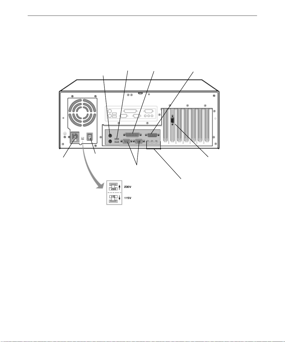
Back View of TD-100, TD-100 PII, TD-250
AC Power Connector
AC Voltage Switch
Mouse
Keyboard
AC Breaker Switch
USB
Parallel(LPT)
Serial(COM)
Game/MIDI
Video(Typical)
Speaker
Line In
Microphone
Page 19

Expansion Slots
Expansion cards are installed in the Accelerated Graphics Port (AGP), Peripheral Component
Interconnect (PCI) and Industry Standard Architecture (ISA) expansion slots in the base unit.
If you purchased any expansion cards from Intergraph Computer Systems, they are installed in
the appropriate expansion slots. The following table defines the expansion slots available on
each system.
5
Slot
1 (Top) PCI AGP
2PCIPCI
3PCIPCI
4PCIPCI
5 ISA PCI or ISA
6 (Bottom) ISA ISA
See Chapter 8, “System Board Overview,” and Chapter 9, “System Board Upgrades,” for
more information.
TD-100 TD-100 PII, TD-250
Connecting to AC Power
To connect the system to AC power:
1. Make sure that the AC voltage switch on the back panel of the base unit is set to the
proper line voltage for your location. If your location uses 115 volts, make sure the
number 100-120 is visible on the switch. If your location uses 230 volts, make sure the
number 200-240 is visible on the switch. See the previous figures.
WARNING If you do not set the AC voltage switch correctly, serious equipment damage may result
when you turn on power to the system.
2. Connect the power cord to the AC Power connector on the back panel of the base unit,
and then to a three-prong, grounded AC wall outlet. See the previous figures.
Page 20
6
Starting the System
WARNING Make sure that the AC voltage switch on the back of the base unit is set to the proper
line voltage for your location. If you do not set the AC voltage switch correctly, serious
equipment damage may result when you turn on power to the system.
To turn on power to the system, press the power breaker on the back panel of computer (to the
– position) and press the power buttons on the base unit and the monitor.
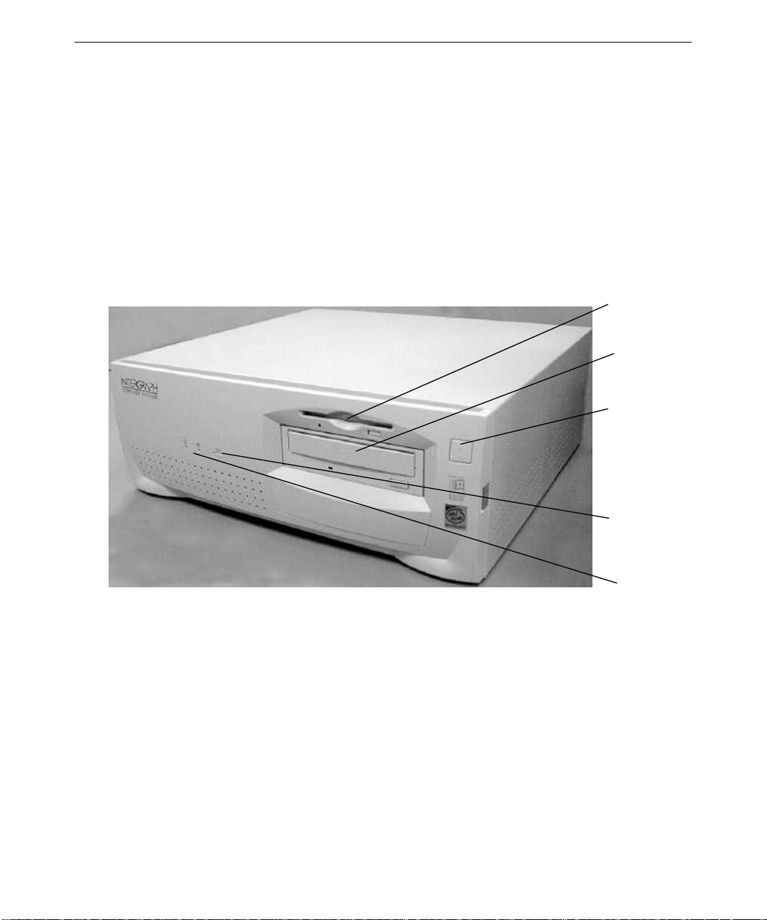
Front View of TD-100
Floppy Disk
Drive
CD-ROM
Drive
Power Switch
Reset Button
Power and
Disk Activity
LEDs
Page 21

Front View of TD-100 PII, TD-250
7
CD-ROM
Drive
Floppy Disk
Drive
Power and
Disk Activity
LEDs
Power Switch
The system starts, and boots to a Setup screen or logon dialog for the operating system. If you
are setting up the system for the first time, an End-User License Agreement (EULA) displays
during the Setup process.
What’s Next?
See Chapter 2, “Setting Up the Software,” for instructions on setting up the operating system
and associated system software.
Page 22

8
Page 23

2 Setting Up the Software
Follow the instructions in this chapter to set up the operating system and associated system
software on your Intergraph Computer Systems TD-100, TD-100 PII, or TD-250.
Preparing for Operating System Setup.............................................................................10
Going Through Operating System Setup .......................................................................... 1 2
Finishing System Setup....................................................................................................13
Creating a Repair Disk.......................................................................................13
Creating System Software Backup Diskettes ..................................................... 13
What’s Next?....................................................................................................................14
9
Page 24

10
Preparing for Operating System Setup
Your system’s primary system disk drive and any additional disk drives were formatted and
partitioned before shipment. In Explorer or My Computer, you can right-click a disk drive
and click Properties to display the drive’s partition size and file system format. To view
partition and format information for all disk drives, you can use Disk Administrator on a
Windows NT system or the fdisk command on a Windows 95 system. See the operating
system documentation and Help for more information on these tools.
The operating system and associated system software is pre-installed on the system’s primary
hard disk drive. Intergraph Computer Systems installed the following system software:
u
Driver software for the mouse
u
Driver software for the installed video display adapter
u
Driver software for the on-board sound processor
u
Quick-Fix Engineering (QFE) update software -- fixes for oper ating system problems or
limitations (if any are needed)
u
InterSite software
You must follow the operating system Setup process to prepare Microsoft Windows NT or
Microsoft Windows 95 for use. Befor e you go through Setup, have the following documents
available:
u
Microsoft’s Start Here (for Windows NT) or Welcome to Windows 95.
u
Documents delivered with any expansion cards or additional peripheral devices purchased
from Intergraph Computer Systems
Get and record the following information:
u
Your name, and the name of your
company or organization:
u
For a system running Windows NT, the
CD Key from the Windows NT CD
case, or the Product ID Number from
Start Here or the registration card:
u
For a system running Windows 95, the
Product ID Number from Welcome to
Windows 95 or the registration card:
u
A username for setting up a use r
account:
Page 25

If the system is connected to a network, get and record the following information from your
network administrator:
u
Computer name for your system:
u
Workgroup name (if the system will be
part of a workgroup):
u
Domain name (if the system will be part
of a Windows NT domain):
If the system is connected to a network that uses the Transmission Control Protocol/Internet
Protocol (TCP /IP), get and record the following TCP/IP networking information from your
network administrator:
u
Internet Protocol (IP) address for your
system:
u
IP subnet mask for your system:
u
IP domain name for your network:
u
IP addre ss for your network’s default
gateway:
11
u
IP addre sses for your network’s
Domain Name System (DNS) servers,
if any:
u
IP addre sses for your network’s
Windows Internet Name Service
(WINS) servers, if any:
Have several blank, formatted diskettes available to create backup diskettes containing system
software.
The Windows NT delivery media contain software and drivers for both Reduced Instruction
Set Computing (RISC)- and Intel-based systems. When installing Windows NT distribution
files, make sure to install them from the \i
386 directory (the Intel software directory) on the
delivery media. For example, if you are installing a device driver from the Windows NT
CD-ROM, key in the following when asked for the path to the file, where drive is the drive
letter for the CD-ROM drive:
drive:\i
386
Page 26

12
Going Through Operating System Setup
The first time you start the system, operating system Setup begins. Early in the Setup process,
an End-User License Agreement displays. After reviewing and accepting the terms of the
agreement, follow the instructions to continue Setup. As you go through Setup, accept the
default settings except as noted in the following text.
On a system running Windows NT or Wi ndows 95:
u
Allow Setup to configure the network only if the system has an installed network adapter,
and only if the system is connected to the network.
u
When prompted to create an Emergency Repair Disk (Windows NT) or a Startup diskette
(Windows 95), do so.
u
If you do not set up a user account during Setup, press ENTER or select OK at the logon
dialog to log on to the operating system.
On a system running Windows NT:
u
On a system shipped from the factory without a CD-ROM drive, the system’s hard disk
drive contains Windows NT Setup files in the
or video display adapter drivers, you can see the i
location of Windows NT Setup files. If you delete the i
hard disk, you must have access to a Windows NT CD-ROM to use Windows NT Setup
files.
C:\i386 directory. When installing network
386 directory when prompted for the
386 directory from the system’s
On a system running Windows 95:
u
While Windows 95 files are being copied to the system, you are prompted for the
Windows 95 Setup boot diskette. This occurs even if the Windows 95 Setup boot
diskette is already inserted in the floppy disk drive. Select OK to continue.
u
During Setup, you are notified that a CD-ROM driver file (such as CDROMDRV.SYS or
M230.SYS) could not be found on the Windows 95 setup boot diskette. In the dialog that
displays, specify that the file should be copied from the diskette in the system’s floppy
disk drive (usually a:\), and then select OK.
u
The system’s primary hard disk drive contains Windows 95 Setup files in the
C:\WINDOWS\OPT IONS\CABS directory, as compressed .CAB files. When installing network
or video display adapter drivers, you can use the
location of Windows 95 Setup files. If you delete the
CABS directory when prompted for the
CABS directory from the system’s
primary hard disk drive, you must have access to a Windows 95 CD-ROM to use
Windows 95 Setup files.
For more information on operating system Setup, and on using the interface features of the
operating system, see the operating system documentation and Help.
Page 27

Finishing System Setup
After operating system Setup is completed, an InterSite Welcome icon (“Press to finish
setup”) displays on the operating system desktop. Double-click this icon, or select
Programs/InterSite/Welcome from the Start menu, to display InterSite Welcome.
InterSite Welcome helps you do the following:
u
Create a repair disk for the operating system.
u
Create backup diskettes of device driver software and other system software products.
u
Learn about Intergraph Computer Systems customer support.
You should take advantage of the tools provided by InterSite Welcome to ensure that your
system is fully ready for use. See InterSite Welcome for more information. Also see the
following sections for information on creating a repair disk and creating backup diskettes.
Creating a Repair Disk
If you did not create an Emergency Repair Disk (Windows NT) or a Startup diskette
(Windows 95) during Setup, use the tools provided by InterSite Welcome to do so. The files
on these diskettes can restore the original contents of a damaged operating system Registry
(that is, at the time the operating system was installed), along with the standard operating
system drivers. You should also update an Emergency Repair Disk or a Startup diskette after
you finish configuring the system.
13
See the operating system documentation and Help for information on creating an Emergency
Repair Disk or a Startup diskette.
Creating System Software Backup Diskettes
Backup diskettes for some device driver software and system software products are not
delivered with the system. Use InterSite Version M a nager, available through InterSite
Welcome, to create system software backup diskettes.
Version Manager lets you create backup diskettes containing device driver software and
system software products that were installed on the system before shipment, and which are not
available on the operating system CD-ROM. You may need these backup diskettes later -- for
example, if you have to reinstall a device driver or the operating system.
WARNING You must create system software backup diskettes after you set up the system
hardware and complete the operating system Setup program. If you do not do this, you
may not be able to reinstall critical system software or the operating system if needed.
Page 28

14
NOTE You may not have to create backup diskettes for all system software. If Version Manager
does not list drivers or other system software products, they are available on the operating
system software CD-ROM or on backup diskettes delivered with expansion cards.
If the system requires Quick-Fix Engineering (QFE) update software, it is included in the
system software available for backup diskette creation. QFE update software contains fixes
for operating system problems or limitations, and is only shipped with the system if it is
needed. If QFE update software is shipped with the system, you should create a QFE backup
diskette for use if you have to reinstall the operating system.
See Version Manage r Help for information on creating system software backup diskettes.
Visit the Intergraph Computer Systems site on the World Wide Web and vendor bulletin
boards for new and updated drivers.
What’s Next?
See Chapter 3, “Configuring the System,” to configure the system for use.
Page 29

3 Configuring the System
Follow the instructions in this chapter to configure your Intergraph Computer Systems
TD-100, TD-100 PII, or TD-250 for use.
Configuring the Video Display......................................................................................... 16
Correcting Video Display Problems...................................................................17
Configuring Networking................................................................................................... 18
Configuring the Sound Processor..................................................................................... 18
Configuring a CD-Recorder Drive...................................................................................18
Configuring a Modem...................................................................................................... 19
Configuring a PC Card Adapter ....................................................................................... 19
Configuring a Tape Drive.................................................................................................20
Configuring a Zip or Jaz Drive......................................................................................... 20
Configuring External SCSI Peripherals............................................................................ 20
Updating the Operating System........................................................................................ 21
Configuring the BIOS....................................................................................................... 21
Updating the BIOS........................................................................................................... 21
What’s Next?....................................................................................................................23
15
Page 30

16
Configuring the Video Display
Your system shipped with the video display driver set to display at a resolution of 800 x 600.
If you want to change the video disp lay to another resolution, be sure your monitor can
support the desired resolution.
To change the video display resolution:
1. Right-click the operating system desktop and select Properties. The Display Pro perties
dialog displays.
2. Select a resolution appropriate for your system’s monitor.
3. On Windows NT systems, click Test to test the new video mode.
4. Click OK, then restart the system.
If the monitor connected to your system does not support a resolution of 800 x 600, you can
reset the video display to another resolution.
To reset the video display resolution on a system running Windows NT:
1. Restart the system.
2. At the boot screen, select the VGA mode option for Windows NT.
3. When the system has started, log on to Windows NT.
4. Right-click the desktop and select Properties. The Display Properties dialog displays.
5. Select a resolution appropriate for your system's monitor.
6. Click Test to test the new video mode, and then click OK.
7. Restart the system.
To reset the video display resolution on a system running Windows 95:
1. Restart the system.
2. When Starting Windows 95 displays, press
displays.
3. Select the Safe Mode option, and then press ENTER. The system boots, using the standard
VGA resolution (640 x 480).
4. Right-click the desktop and select Properties. The Display Properties dialog displays.
5. Select a resolution appropriate for your system's monitor, and then click OK.
6. Restart the system.
F8. The Windows 95 Startup Menu
Page 31

See the documentation and README.TXT files accompanying the installed video adapter and
driver for detailed configuration instructions. For information on using the Display Properties
or Display Settings dialog, see the operating system documentation and Help.
Correcting Video Display Problems
If the system’s video display is black, not synchronized, or distorted after you restart the
system, you may have a video configuration pro blem.
On a system running Windows NT, use the Last Known Good option to return the system to
the last known good configuration recorded by Windows NT.
To use the Windows NT Last Known Good option:
1. Power down and restart the system.
2. When prompted, press the space bar to invoke the Last Known Good menu.
If the Last Known Good option fails, or if Windows 95 is installed, restart the system in VGA
mode to correct the video configuration problem.
To restart the system in VGA mode:
17
1. Power down and restart the system.
2. On systems running Windows NT, select the V GA mode option at the boot screen.
On systems running Windows 95, press the
F8 key when Starting Windows 95...
displays on the screen, then select Safe Mode.
When the operating system desktop displays, right-click the desktop background and select
Properties. The Display Properties dialog displays. Check for the following common
configuration problems and solutions.
u
A multi-sync monitor is connected to the system, but a multi-sync monitor type is not
selected, and the display driver cannot determine this by querying- the monitor. Select an
appropriate multi-sync monitor type.
u
Selected resolution, depth, or refresh rate is not supported by the multi-sync monitor. Try
using different video d i splay settings.
u
The Dual Screen option is selected, but only one video card is detected. Clear the Dual
Screen option.
u
A multi-sync monitor is selected, but a monitor with different video is connected to the
system. Select an appropriate monitor type.
u
The monitor selection doesn’t match the multi-sync monitor attached to the system.
Restart the system in VGA mode, then select a new monitor.
Page 32

18
u
A graphics resolution and color depth has been selected that exceeds installed display
memory. Restart the system in VGA mode, then open Display in the Control Panel to
reinstall and configure the display driver as described in the video d isplay adapter
documentation delivered with the system.
After you’ve configured the video display, restart the system and select the non-VGA version
of the appropriate operating system to use the new configuration.
If problems persist, contact the Customer Response Center for help.
Configuring Networking
If you purchased a network adapter with your system, it was installed before shipment. You
must configure the operating system to use the network a dapter. To do this, you may have to
install network driver software and network adapter control software, and then change
operating system settings to enable networking. Before you configure networking, make sure
that the system has an installed network adapter, and that the network adapter is connected to a
network.
To configure networking, open Network in the Control Panel. Follow the instructions in the
dialogs to set up the system to use a network. Be sure to set up the appropriate network
protocols, such as TCP/IP and NetBEUI, for the network you are connecting to.
See the documentation for the installed network adapter for detailed configuration
instructions. See the operating system documentation and Help for information on setting up
the system to use a network.
Configuring the Sound Processor
Your system includes an on-board sound processor, which was configure d before shipment.
An on-board speaker provides basic sound capability. You can use the operating system’s
sound control programs to control the on-board speaker, and to control a microphone and
external speakers if you purchase them.
For information on using the sound control programs, see the operating system documentation
and Help.
Configuring a CD-Recorder Drive
If you purchased a CD-Recorder (CD-R) drive with your system, it was installed before
shipment. If you purchased the CD-R drive in place of the standard CD-ROM drive, the
Page 33

driver software enabling it to be used as a standard CD-ROM drive was installed before
shipment. To use the CD-R drive to record CDs, you must install the CD-R driver software
and any associated application software programs.
See the documentation delivered with the CD-R drive for detailed software installation and
configuration instructions.
Configuring a Modem
If you purchased an internal modem with your system, it was installed before shipment. To
use the modem, you may have to install the driver software and any associated applications
software programs. You may also have to change operating system settings to enable the
system to use the modem.
See the documentation delivered with the modem for configuration instructions. See the
operating system documentation and Help for information on using a modem with the system.
Configuring a PC Card Adapter
19
If you purchased a PC Card adapter with your system, it was installed before shipment. To
use the PC Card adapter, you may have to install the driver software and any associated
application software programs.
You may have received a diskette titled CardWizard for Windows NT. This diskette contains
the latest Windows NT 4.0 driver and CardWizard software for the PC Card adapter. You
must install this software on the system to ensure the adapter works correctly with Windows
NT 4.0
u
If you received this diskette, install the software from the diskette after setting up the
system hardware and completing the operating system Setup. See the
README.TXT file
and the CardWizard for Windows NT User’s Guide delivered on the diskette for
installation instructions.
u
If you did not receive this diskette, the latest driver and CardWizard software is already
installed on the system. You can make a backup diskette for this software using InterSite
Version Manager. See Version Manager Help for more information on creating system
software backup diskettes.
NOTE If you reinstall Windows NT 4.0 Service Pack 3 software on a system with a PC Card adapter,
you must install the CardWizard software after installing Service Pack 3 software. If you do
not do this, you may experience problems when using the PC Card adapter. This is an
exception to the general rule that you must reinstall Service Pack 3 software any time you
change hardware or software components on a system.
Page 34

20
Depending on your system’s configuration, you may have to reserve an interrupt reque st
(IRQ) for a PC Card device inserted in the PC Card adapter. If the CardWizard software
reports that the driver for the PC Card device failed to start, you should reserve an IRQ for
that PC Card device. The CardWizard will display the IRQ that you should reserve. See
Chapter 10, “BIOS Setup,” for information on reserving IRQs in your system’s BIOS. See the
documentation delivered with the PC Card adapter for detailed software installation and
configuration instructions.
Configuring a Tape Drive
If you purchased an internal tape drive with your system, it was installed before shipment. On
a system running Windows 95, you may have to install the driver software and any associated
applications software programs to use the tape drive. On a system running Windows NT, you
can use the Windows NT Backup tool to run the tape drive; select Programs/Administrative
Tools/Backup from the Start menu.
See the documentation delivered with the tape drive for configuration instructions. See the
device documentation, operating system documentation, and Help for information on using the
tape drive.
Configuring a Zip or Jaz Drive
If you purchased an internal Zip or Jaz drive with your system, it was installed before
shipment. To use the Zip or Jaz drive, you may have to install the driver software and any
associated applications software programs.
See the documentation delivered with the Zip or Jaz drive for configuration instructions. See
the device documentation, operating system documentation, and Help for information on using
the Zip or Jaz drive.
Configuring External SCSI Peripherals
The optional SCSI adapter is designed to support Fast SCSI-2 devices. If you connect SCSI-1
devices to the adapter, data transfer rates are limited to the device’s speed.
CAUTION Using a non-compliant SCSI-1 device with your system may cause your system to stop
working, or lead to other unpredictable results.
See the documentation delivered with the SCSI adapter for more information on configuring
and using the SCSI adapter.
Page 35

Updating the Operating System
Microsoft Service Packs contain the latest improvements and system fixes for Microsoft
operating systems. Microsoft created Service Packs for post-release support. You can obtain
Service Packs from Microsoft’s World Wide Web and FTP sites free of charge.
CAUTION If Intergraph provides a Service Pack through the IBBS or with a product or system, it has
been certified against Intergraph hardware as described in the announcement of its
availability. If you obtain a Service Pack from any other source, be aware that it may not be
certified against your Intergraph hardware.
Configuring the BIOS
Your system’s Basic Input/Output System (BIOS) records basic system operating parameters,
such as the boot sequence, hard drive settings, and the type of video display. The system’s
operating parameters are set in the BIOS before shipment, and you should not need to change
them immediately. However, you may want to configure some aspects of system operation
later by changing BIOS settings.
The BIOS is stored in fresh Erasable-Programmable Memory (EEPROM) on the system
board, and reads the system parameters in the system’s Complementary Metal-Oxide
Semiconductor (CMOS) Random-Access Memory (RAM). When you turn off power to the
system, a battery provides power to CMOS RAM, which retains the system parameters. Each
time you turn on system power, the BIOS uses the stored parameters to configure the system.
21
To run the BIOS Setup program:
1. Restart the system.
2. When the BIOS version displays on the screen, press
Chapter 10, “BIOS Setup,” provides de tailed information on the BIOS, including instructions
for running the BIOS Setup p rogram to change BIOS parameter settings, and a list of available
BIOS parameters and their default settings.
Updating the BIOS
You may want to update the system’s current BIOS with a new version to take advantage of
fixes or enhancements. New versions of the system’s BIOS are made available on the Support
pages of the Intergraph Computer Systems World Wide Web site and from the Intergraph
Bulletin Board Service (IBBS). See the Preface of this document for details.
To update the system’s BIOS:
F2
Page 36

22
1. Record the BIOS parameter settings for your system. To do this, restart the system, and
press
F2 during boot to run BIOS Setup. Write down the setting for each parameter; then
exit from BIOS Setup and let the system continue to boot.
2. Download the
PHLASH product for the TD-100, TD-100 PII, or TD-250 to a directory on
your system from the Support pages on the World Wide Web or from the IBBS.
3. Use an unzip utility to open the
PHLASH product and extract the files from it.
4. Insert a blank, formatted diskette into the system’s floppy disk drive.
5. In the directory containing the
PHLASH files, run INSTALL.BAT. This creates a boot
diskette with the new BIOS file and the BIOS flash programming utility.
6. After
INSTALL.BAT completes, leave the diskette in the floppy disk drive and restart the
system.
7. At the MS-DOS command prompt, run
example, if the BIOS file on the boot diskette is named
PHLASH.EXE to update the current BIOS. For
BIOS.ROM, you would key in the
following command to update the BIOS:
phlash bios.rom
WARNING Do not turn off system power while the BIOS update is in progress, as it may lead to
system failure.
8. After the BIOS is updated, the system shuts down. Remove the diskette from the floppy
disk drive and label it BIOS Update date, where date is today’s date.
9. Turn on power to the system.
10. As the system boots, press
F2 when you see a message like the following:
PhoenixBIOS Version n.n Release n.n 430TX-I006
BIOS Setup starts.
11. Make sure that all parameter settings match the settings you recorded before you updated
the BIOS. Change any that do not match the settings you recorded.
12. Save any changes and exit from BIOS Setup.
13. Restart the system.
For more information on the phlash command, type phlash /? at the MS-DOS command
prompt. For more information on updating the BIOS, see the
the
PHLASH product. For more information on the BIOS Setup program, see Chapter 10,
README.TXT file delivered with
“BIOS Setup.”
Page 37

What’s Next?
See Chapter 4, “Operating Notes,” to learn things you may need to know when operating the
system.
See Chapter 5, “Installing System Software,” if you need to reinstall the operating system and
associated system software for any reason.
See Chapter 6, “Expanding the System,” for information on expanding the capabilities of the
system.
23
Page 38

24
Page 39

4 Operating Notes
Use the information in this chapter when operating your Intergraph Computer Systems
TD-100, TD-100 PII, or TD-250.
Observing Operating Precautions............................................................................................ 26
Using the Keyboard................................................................................................................. 26
Using the Mouse...................................................................................................................... 27
Using the Floppy Disk Drive................................................................................................... 28
Using the CD-ROM Drive....................................................................................................... 28
Starting and Shutting Down the System.................................................................................. 29
Starting MS-DOS from the Startup Menu (Windows 95)....................................................... 30
Using On-Board Sound........................................................................................................... 30
Using InterSite Programs (Windows NT) ............................................................................... 31
Updating an Emergency Repair Disk or a Startup Diskette..................................................... 31
Ensuring PC Card Support and Operation............................................................................... 32
Cleaning the System................................................................................................................ 32
25
Page 40

26
Observing Operating Precautions
Observe the following precautions when operating the system:
u
When restarting the system, use the operating system controls instead of turning the
power switch off and on. Use the power switch only when instructed, or as the last
alternative for restarting the system.
u
Never turn off power to the base unit when the disk access LED is lit.
u
After turning off power to the base unit, wait at least 30 seconds before turning the power
on again, to ensure that the disk drives have stopped and the system has power-cycled
properly.
u
Run virus scan software periodically to ensure that your system’s files and programs are
not corrupted.
Using the Keyboard
The keyboard delivered with the system includes the following features:
u
PS/2 compatibility.
u
104 standard keys.
u
Function keys (F1 through F12) at the top, for special functions used by application
programs.
u
Windows keys at the bottom, for use with the Windows NT and Windows 95 operating
system. Pressing either Windows Logo key displays the operating system Start menu.
Pressing the Application Logo key displays an application-specific pop-up menu.
u
Arrow keys for moving the cursor up, down, right, and left on the sc reen.
u
Numeric keys in a numeric keypad.
Some keyboard keys have speci al functions, as follows:
Key
ESC Usually assigned to an application-specific function; often used to exit.
PRINT SCRN Depending on the application in use, prints the displayed screen to a printer.
SCROLL LOCK Prevents the screen from scrolling.
PAUSE Temporarily suspends screen scrolling or some operations.
CAPS LOCK Types all letters as capitals.
NUM LOCK Activates the numeric keypad.
CTRL Used with another key for application -specific functions.
Function
Page 41

Key Function
ALT Used with another key for application-specific functions.
DELETE Deletes characters.
You can use the Windows Logo keys in combination with other keys to perform certain
operating system functions, as follo ws:
27
Windows Logo Key Combination
Windows Logo + F1 Display a pop-up menu for the selected object
Windows Logo +
Windows Logo +
Windows Logo +
Windows Logo +
Windows Logo +
TAB Activate the next button on the taskbar
E Run Explorer
F Run Find Document
CTRL + F Run Find Computer
M Minimize all
SHIFT + Windows Logo +
Windows Logo +
Windows Logo +
R Display the Run dialog
PAUSE/BREAK Perform a system function
Using the Mouse
The mouse is a PS/2-compatible tracking device that controls the movement and positioning
of the pointer (or cursor) displayed on the screen in a graphical display environment. The
basic techniques for using the mouse are as follows:
Action
Point Move the mouse to point to your selection on the screen.
Click Press and release the left mouse button once.
Double-click Press and release the left mouse button twice.
Drag Press and hold the left mouse button, then move the mouse. Release the button
Right click Press and release the right mouse button once.
Description
when you finish dragging your selection to a new location.
Action
M Undo minimize all
NOTE The double-click speed is timed. If you double-click too slowly, the system responds as if you
clicked twice. You can adjust the double-click speed using the operating system’s Mouse
application.
To use the mouse, make sure it is properly connected to the system. Place the mouse on a
clean, flat surface, such as a desktop or a mouse pad. Move the mouse across the flat surface
to move the pointer across the screen.
Page 42

28
Using the Floppy Disk Drive
The system’s floppy disk drive occupies a 3.5-inch peripheral device bay, and is accessible
through a 3.5-inch slot on the front of the base unit. The drive accepts standard 3.5-inch 720
KB and 1.44 MB diskettes.
Follow these guidelines to use the floppy disk drive:
u
To insert a diskette into the drive, position the diskette so the arrow embossed on the
diskette faces up. Slide the diskette into the floppy disk slot and through the drive door,
and push it into the drive until it clicks into place and the eject button next to the slot pops
out.
u
Before removing a diskette, ensure the drive LED is not lit. The LED lights green to
indicate floppy disk drive activity.
u
Remove the diskette by pushing the eject button adjacent to the floppy disk slot, and then
pulling the diskette out of the drive.
u
To protect the data on a diskette from being overwritten or erased, slide the write-protect
tab on the diskette toward the diskette edge until it snaps into place. When the writeprotect opening is uncovered, the disk can be read from, but not written to. To write data
to a diskette, ensure the write-protect opening is covered.
Using the CD-ROM Drive
The system’s CD-ROM drive occupies a 5.25-inch peripheral device bay, and is accessible
through a tray or a slot a t the front of the base unit. The CD-ROM drive is an Enhanced
Integrated Device Electronics (EIDE) device that features MPC-3 compatibility and multisession Photo CD support. The drive also supports software ejection of discs and has an
external amplified headphone jack.
To use the CD-ROM drive:
u
To insert a disc into a tray-load CD-ROM drive, press the eject button to extend the tray.
Place the disc, printed side up, in the tray and press the eject button to load the disc.
u
To insert a disc into a slot-load CD-ROM drive, insert the disc, printed sid e up, into the
slot.
u
To eject a disc from the CD-ROM drive, press the eject button.
NOTE The software application being used may prevent the compact disc from ejecting. If so, run
the proper application command to eject the compact disc.
u
The media player application program(s) included with the operating system allows you
to listen to audio compact discs. Insert an audio compact disc, printed side up, into the
Page 43

CD-ROM drive and start the media player application. Adjust the volume using the
operating system’s sound control programs.
Starting and Shutting Down the System
After you complete Setup and start the system for the first time, you can start and stop the
system as needed.
To start the operating system:
1. Turn on power to the system.
2. On a system running Windows 95, the ope rating system starts.
On a system running Windows NT Worksta tion 4.0, the boot menu displays; select
Windows NT to display the logon dialog.
To log on to the operating system:
29
1. If the logon dialog does not display, press
2. Type a username and password into the appropriate boxes.
3. If appropriate, type a domain name.
4. Select OK or press
To log off, restart, or shut down the operating system:
1. Select Shut Down from the Start menu.
2. Perform one of the following steps, as appropriate:
−
To log off the operating system, select the “close all programs” option (if
given), and then select OK.
−
To restart the system, select the restart option, and then select OK.
−
To shut down the system, select the shutdown option, and then select OK.
After shutting down or logging off the operating system, you can turn off the power to the base
unit and monitor.
For more information on starting and stopping the operating system, see the operating system
documentation and Help.
ENTER.
CTRL+ALT+DELETE to display it.
Page 44

30
Starting MS-DOS from the Startup Menu (Windows
95)
You can start the system in MS-DOS from the Windows 95 Startup menu. If you do this, the
drivers for the CD-ROM drive and the mouse do not load automatically. To enable use of the
CD-ROM drive and the mouse in MS-DOS, you must load their drivers manually after the
system starts in MS-DOS.
To start the system in MS-DOS from the Windows 95 Startup menu:
1. Restart the system.
2. When the message Starting Windows 95 displays, press
Startup Menu displays.
3. Select the Command Prompt option, and then press ENTER.
To enable the CD-ROM drive and the mouse:
1. Add the following command line to
device=c:\cdromdrv.sys /c:msdos001
2. Add the following command line to
c:\mscdex /d:mscd001
3. Restart the system and start MS-DOS from the Windows 95 Startup menu.
Using On-Board Sound
Your system includes a Sound Blaster-compatible on-board sound processor and a cabinet-
mounted speaker. You can use the operating system’s sound control and media player
programs with the speaker to give your system basic audio capability. For example, you can
play audio files and audi o CDs through the speaker. If you purchase a microphone and
external speakers, you can connect them to the on-board sound processor for higher quality
audio capability.
For information on using the sound control programs, see the operating system documentation
and Help.
F8. The Windows 95
CONFIG.SYS:
AUTOEXEC.BAT:
Page 45

Using InterSite Programs (Windows NT)
TD-100, TD-100 PII, and TD-250 systems running Windows NT ship with the following
InterSite programs:
u
InterSite Version Manager is a tool for creating system software backup diskettes, and for
updating device drivers and other system software products installed on the system.
u
InterSite DMI Console gives easy access to the system’s status and configuration
information. The Console is based on the Desktop Management Interface (DMI), through
a window containing a graphical information tree view pane, a service provider
component information pane, and a message pane. DMI Console works with the Desktop
Management Interface (DMI), a technology standard that enables the effective
management of personal computer s (PCs).
u
InterSite Watchdog is a system monitoring tool with remote monitoring capabilities. You
can install Watchdog on a system running the Wind ows NT, and use it to monitor
workstations and servers also running Windows NT.
From the operating system Start menu, go to Programs/InterSite to find the InterSite programs
on your system. See the online Help for each InterSite program for more information on how
to use the program.
31
Updating an Emergency Repair Disk or a Startup Diskette
You may have created an Emergency Repair Disk (Windows NT) or a Startup diskette
(Windows 95) during first-time startup, or through InterSite Welcome. I f you did not, you
should create the appropriate diskette after you finish configuring the system. If you did, you
should update it any time you change the configuration of the system. The files on the
Windows NT Emergency Repair Disk can restore the original contents of a damaged
operating system Registry (that is, at the time the operating system was installed), along with
the standard operating system drivers. Use the Startup diskette to start the system in the event
you have trouble starting W i ndows 95.
See the operating system documentation for information on creating an Emergency Repair
Disk or a Startup diskette.
Page 46

32
Ensuring PC Card Support and Operation
The optional PC Card adapter is used with devices based on standards developed by the
Personal Computer Memory Card International Association (PCMCIA). Windows NT and
Windows 95 provide support for PC Card devices.
NOTE PC Card support on TD-100, TD-100PII, and TD-250 systems includes CardWizard for
Windows NT. For more information, see the vendor documentation accompanying the
software.
If you will be using a PC Card hard disk device (ATA or AT type) with a system running
Windows NT, make sure the device drivers that control PC Card hard disk operation are set to
start correctly. Set both the Atdisk device and the Pcmcia device to start as System devices.
Do this before inserting a PC Card hard disk device in the PC Card adap ter. If you do not,
anomalous behavior may result -- for example, the PC Card hard disk drive may not be
detected by Windows NT, or may be detected as the system drive (drive C).
NOTE You must shut down the system before inserting a PC Card device in the PC Card adapter.
When you restart the system, Windows NT will recognize the PC Card device.
To change the startup type for device drivers that control PC Card hard disks:
1. Open Devices in the Windows NT Control Panel. The Devices dialog displays.
2. Highlight the device in the Device list; then select Startup. The Device dialog displays.
3. Under Startup Type, select system; then select OK.
4. In the Devices dialog, select Close.
See the operating system documentation and Help for more information on PC Card device
support.
Cleaning the System
Follow these guidelines for cleaning the system:
Item
Mouse On the bottom of the mouse, a retaining ring holds the tracking ball in
Keyboard Dust with a dry cloth. Aerosol cleaners are commercially available to
How To Clean
place. Remove the retaining ring and turn the mouse over; the tracking
ball will fall out. Blow gently into the opening. Clean the tracking ball
and rollers with a cotton swab and alcohol. Replace the tracking ball
and the retaining ring.
Page 47

Item How To Clean
remove the dust between the keys of the keyboard. Never allow
moisture on the keyboard or the surface beneath the keys.
Exterior Surfaces Clean the exterior surfaces of the base unit and the monitor screen with a
mild cleaning detergent and a clean cloth.
CAUTION Turn off power to the system before cleaning the exterior surfaces, the mouse, or the
keyboard. Do not clean the CD-ROM drive.
33
Page 48

34
Page 49

5 Installing System Software
Follow the instructions in this chapter if you have to reinstall the operating system and
associated system software on your Intergraph Computer Systems TD-100, TD-100 PII, or
TD-250.
Before You Begin.................................................................................................................... 36
System Software Products....................................................................................................... 36
Windows NT Workstation 4.0................................................................................................. 38
Enabling Bus Mastering for IDE/ATAPI Devices.................................................... 39
Windows 95............................................................................................................................. 39
Installing Windows 95 with an Installed Network Adapter....................................... 41
Enabling Bus Mastering for IDE/ATAPI Devices.................................................... 41
Updating the Operating System............................................................................................... 42
35
Page 50

36
Before You Begin
Have the following items available:
u
The information you recorded in Chapter 2, “Setting Up the Software.”
u
Operating system software CD-ROM, associated diskettes, and documentation. Make
sure you have the Setup diskettes (Windows NT Workstation 4.0) or the Boot diskette
(Windows 95), as appropriate.
u
Backup diskettes you created according to instructions in Chapter 2, “Setting Up the
Software.”
u
Backup diskettes and documentation delivered with any expansion cards or additio nal
peripheral devices purchased from Intergraph Computer Systems.
u
The Late-Breaking News document delivered with your system, if applicable.
You can find the system software on backup diskettes that you created, on diskettes provided
by Intergraph Computer Systems, or on the operating system CD-ROM. If you did not create
backup diskettes of drivers or other system software products, they are probably available on
the operating system CD-ROM or on backup diskettes delivered with expansion cards.
NOTE You must install certain drivers from backup diskettes. The correct driver versions may not be
on the operating system CD-ROM.
Driver software is routinely improved and updated. Visit the Intergraph Computer Systems
site on the World Wide Web and vendor bulletin boards for new and updated drivers.
Review the Late-Breaking News document delivered with your system for any additional tasks
you may have to perform during reinstallation.
System Software Products
The following table lists drivers and other system software products installed on various
configurations of TD-100, TD-100 PII, and TD-250 systems. Names of system software
products created by the InterSite Version Manager or available from the Intergraph online
services are listed. Products available for your system, but not listed here, are available on the
operating system software CD-ROM or are delivered with an expansion card or additional
peripheral device.
Page 51

System Software Product Windows NT 4.0 Windows 95 Online Services
SVB-6171 video driver CIRRUS2DNT CIRRUS2DW95 -
SVB-6183, SVB-6187 video driver
Millennium II video driver
AccelSTAR II video driver
Mouse driver (TD-100 PII, TD-250) -
Sound driver (TD-100 PII, TD-250)
Sound driver (TD-100)
56 Kbps modem driver 56
3Com 3C90x network adapter driver 3
Olicom Token Ring network adapter driver
Intel PRO/100+ network adapter driver
SCSI adapter driver 2940
InterSite Welcome
InterSite Version Manager
InterSite DMI Console
InterSite Watchdog
InterSite SMART disk driver
PCMCIA CardWizard software
Windows 95 boot diskette n/a
PIIX4 patch for Windows 95 n/a
Internet Explorer 4.01 settings n/a
Quick-Fix Engineering software
BIOS/flash utility (TD-100 PII, TD-250) - -
ATIGRADVRNT ATIGRADVRW95 -
MILL2DRVNT MILL2DRVW95 -
ACCEL2DRVNT ACCEL2DRVW95 -
PMOUSE ESSDRVNT ESSDRV95 -
CS4237BNT CS4237BW95 -
KMODEM 56KMODEM -
COM3C90X 3COM3C90X -
PCITOKRNG PCITOKRNG PRO100PLUS PRO100PLUS -
SCSIDRV 2940SCSI95 WELCOME WELCOME VERMANAGER VERMANAGER DMI n/a WATCHDOG n/a SMARTDRV n/a CARDWIZNTDRV n/a -
W95BOOTDSK PIIX4W95R2 -
IE4SETTINGS -
QFE_NTW QFE_WIN95 -
PHLASH
BIOS/flash utility (TD-100) - - PHLASHPRO100
37
Page 52

38
Windows NT Workstation 4.0
Depending on your system’s configuration, you will need some or all of the following system
software during the installation process:
u
Video display adapter driver
u
Network adapter driver
u
Sound processor driver
u
Mouse driver
u
QFE update software
Follow the instructions in Start Here to install Windows NT. As you install the operating
system, select the default responses during the Setup process, except for the following:
u
Allow Setup to configure the network only if you have an installed network adapter, and
only if the system is connected to the network.
u
Create an Emergency Repair Disk when prompted.
After installing the operating system, do the following:
u
Install drivers or other system software from any backup diskettes. System software
delivered on backup diskette is usually more current than system software on the
operating system CD-ROM. Alternatively, you can install the drivers or other system
software from the Windows NT CD-ROM if you do not have them on diskette.
u
Perform any additional installation and configuration tasks described in the Late-Breaking
News document delivered with your system.
u
Configure the system as described in Chapter 3, “Configuring the System.”
u
If your system was running Windows NT 4.0 Service Pac k software, install this software
after installing drivers and other system software, and after installing any application
software products.
u
If you created a Quick-Fix E ngineering (QFE) backup diskette during system
configuration, install the QFE update software. Install QFE software after installing any
Windows NT 4.0 Service Pack software. See the
README.TXT file on the QFE diskette
for more information.
u
Perform any operational changes required for your system as described in Chapter 4,
“Operating Notes.”
Page 53

Enabling Bus Mastering for IDE/ATAPI Devices
Your system may have shipped with bus mastering for IDE/ATAPI device s enabled. If you
reinstall Windows NT 4.0 and Service Pack 3 software, you may want to re-enable
IDE/AT API bus mastering.
NOTE On systems that ship with a TR-4 tape drive, a Zip drive, or a CD-Recorder drive, bus
mastering is not enabled. See documentation delivered with these devices for more
information.
To enable IDE/ATAPI bus mastering:
1. Ensure that the operating system, Service Pack 3 software, and QFE update software
(
QFE_NTW) are installed.
NOTE The QFE update software includes an updated ATAPI device driver that should be installed
after Service Pack 3.
NOTE For reasons of system performance, if a TR-4i tape drive or a Zip drive is installed, do not
enable DMA use on the IDE channel to which the drive is connected. A TR-4i tape drive or
Zip drive is usually connected to Channel 0 when installed at the factory.
2. Insert the Windows NT 4.0 Service Pack 3 CD-ROM into your system’s CD-ROM drive.
39
3. In Explorer or File Manager, navigate to the \
4. Double-click
5. The Current DMA Usage boxes indicate which channels have IDE/ATAPI devices. For
each channel with an IDE/ATAPI device, click Enabled; then click OK.
6. Restart the system.
Windows 95
Depending on your system’s configuration, you will need some or all of the following system
software during the installation process:
u
Windows 95 Operating System Service Release 2.5
u
PIIX4 IDE patch
u
Video display adapter driver
u
Network adapter driver
u
Sound card driver
u
Mouse driver
u
QFE update software
SUPPORT\UTILS\I386 directory.
DMACHECK.EXE. The ATAPI DMA support dialog displays.
Page 54

40
To install Windows 95:
1. Insert the Windows 95 boot diskette in the floppy disk drive.
2. Insert the Windows 95 CD-ROM in the CD-ROM drive.
3. Start (or restart) the system.
4. At the Windows 95 Startup Menu, select the option to install Windows 95.
If you are installing Windows 95 on a system on which another operating system or a previous
version of Windows 95 exists, you may have to partition and format the system’s hard disk
before installing Windows 95. An option on the Startup Menu allows you to exit to MS-DOS
and use the fdisk and format commands.
CAUTION Be sure to make a backup copy of your data and/or programs before partitioning and
formatting the system’s hard disk. All data on the hard disk will be destroyed during the fdisk
and format process. Once you have completed these tasks and reinstalled Windows 95, you
must reinstall any application software and data that you want to use.
CAUTION Make sure that all disk drives attached to the system are partitioned, and formatted with the
File Allocation Table (FAT) file system, before attempting to install Windows 95, or the
installation will fail.
Follow the instructions in Introducing Windows 95 to install Windows 95. As you install the
operating system:
u
Select the default responses during the Setup process.
u
Allow Setup to configure the network only if you have an installed network adapter, and
only if the system is connected to the network.
u
Create a Startup diskette when prompted.
u
While Windows 95 files are being copied to the system, you are prompted for the
Windows 95 Setup boot diskette. This occurs even if the Windows 95 Setup boot
diskette is already inserted in the floppy disk drive. Select OK to continue.
u
During Setup, you are notified that a CD-ROM driver file (such as CDROMDRV.SYS or
M230.SYS) could not be found on the Windows 95 Setup boot diskette. In the dialog that
displays, specify that the file should be copied from a:\, and then select OK.
After installing the operating system:
u
Install Universal Serial Bus (USB) support software from the Windows 95 CD-ROM.
See the instructions in the
u
Install the PIIX4W95 product, a software patch that enables Windows 95 to work properly
with the PIIX4 controller on the system board. See the
USB.TXT file on the Windows 95 CD-ROM.
README.TXT file delivered with
the product.
CAUTION Install PIIX4W95 after you install USB support, or system problems may result.
Page 55

u
Install drivers or other system software from any backup diskettes. System software
delivered on backup diskette is usually more current than system software on the
operating system CD-ROM. Alternatively, you can install the drivers or other system
software from the Windows 95 CD-ROM if you don’t have them on diskette.
u
Perform any additional installation and configuration tasks described in the Late-Breaking
News document delivered with your system.
u
Configure the system as described in Chapter 3, “Configuring the System.”
u
If you created a Quick-Fix E ngineering (QFE) backup diskette during system
configuration, install the QFE update software. See the
README.TXT file on the QFE
diskette for more information.
u
Perform any operational changes required for your system as described in Chapter 4,
“Operating Notes.”
Installing Windows 95 w i th an Installed Network Adapter
If you reinstall Windows 95 on a system with an installed network adapter, the adapter may
not function after completing Setup.
To re-enable network adapter operation after installing Windows 95:
41
1. Go to Start/Settings/Control Panel/System/Device Manager.
2. In the list of devices displayed, double-click Other Devices.
3. Under Other Devices, click the network adapter installed in your system, and then click
Remove.
4. Close Device Manager, and then restart the system.
5. As Windows 95 starts, it should detect the network adapter and prompt you to install the
network adapter’s driver software. Follow the instructions displayed. You will need the
diskette containing the network adapter’s driver software.
Enabling Bus Mastering for IDE/ATAPI Devices
Systems that support UDMA shipped with bus mastering for IDE/ATAPI devices enabled. If
you reinstall Windows 95 on one of these systems, you should also enable IDE/ATAPI bus
mastering.
To enable IDE/ATAPI bus mastering:
1. Ensure that Windows 95 OEM Service Release 2.0 (OSR2.0) or later is installed on your
system.
2. Ensure that the QFE update software (
QFE_W95) is installed.
Page 56

42
NOTE The QFE update software includes an ATAPI device driver that supports DMA bus mastering.
3. Go to Start/Settings/Control Panel/System/Device Manager/Disk Drives.
4. Click a disk drive, then click Properties, and then click Settings.
5. Click the DMA check box, and then click OK.
6. Repeat steps 4 and 5 for any additional disk drives.
7. In Device Manager, click the CD-ROM drive, then click Properties, and then click
Settings.
8. Click the DMA check box, and then click OK.
9. Restart the system.
Updating the Operating System
Microsoft Service Packs and Service Releases contain the latest improvements and system
fixes for Microsoft operating systems. Service Packs and Releases are created by Microsoft
for post-release support. You can obtain them from Microsoft’s World Wide Web and FTP
sites free of charge.
CAUTION If Intergraph provides a Service Pack or Service Release through the IBBS or with a product
or system, it has been certified against Intergraph hardware as described in the
announcement of its availability. If you obtain a Service Pack or Service Release from any
other source, be aware that it may not be certified against your Intergraph hardware.
Page 57

6 Expanding the System
Use to the information in this chapter to expand your Intergraph Computer Systems TD-100,
TD-100 PII, or TD-250 system.
Adding External Peripheral Devices....................................................................................... 44
Opening the Base Unit............................................................................................................. 44
Taking Antistatic Precautions..................................................................................................46
Adding Expansion Cards......................................................................................................... 47
Installing Expansion Cards........................................................................................ 48
Configuring Expansion Cards................................................................................... 48
Adding System Memory.......................................................................................................... 49
Adding Internal Peripheral Devices........................................................................................ 50
Opening the Upper 5.25-Inch Peripheral Bay........................................................... 52
Removing or Replacing Internal 3.5-Inch Devices ................................................... 52
43
Page 58

44
Adding External Peripheral Devi ces
You can add external peripheral devices to the system in several ways:
u
Connect a modem, printer, or other serial (RS-232 compatible) device to a serial port.
Two serial ports are provided. Use cables with 9-pin DB9 connectors. For a cable with a
25-pin DB25 connector, use a 9-pin to 25-pin adapter.
u
Connect a printer or another parallel (Centronics compatible) device to the parallel port.
Use a cable with 25-pin DB25 connectors.
u
Connect a Universal Serial Bus (USB) device to a USB p ort (only on a system running
Windows 95; Windows NT 4.0 does not currently support USB peripherals). Two USB
ports are provided.
u
On a system equipped with a Small Computer System Interface (SCSI) adapter, connect
SCSI devices to the SCSI port on the adapter. See the documentation delivered with the
SCSI adapter for more information.
u
On a system equipped with a PC Card adapter, insert one or more PC Card devices in the
optional PC Card adapter. You can insert two Type I, Type II, and Type III PC Card
devices in the adapter. Use only Exchangeable Architecture (ExCA) PC Card devices.
See Chapter 4, “Operating Notes,” and the documentation delivered with the PC Card
adapter for more information.
See Chapter 1, “Setting Up the Hardware,” to locate ports on the back of the base unit.
All ports and cables are keyed or molded to make connecting the cables easy. If you
encounter difficulty connecting a cable, ensure that you are aligning the cable connector
correctly with the port.
CAUTION If you do not use Intergraph cables, use shielded cables to prevent excessive electromagnetic
interference (EMI). Intergraph cables are designed to reduce the amount of EMI produced by
the system.
Opening the Base Unit
To gain access to the system’s internal components, you must remove the side panel. You
may also have to remove the front panel to gain access to some components, such as frontaccessible peripheral devices.
Before opening the base unit:
1. Turn off power to the system and to the monitor.
2. Disconnect all cables from the back of the base unit.
Page 59

TD-100
To remove the top cover:
1. Press the two push buttons on both sides near the front as shown in the following figure.
2. Push the cover back and then up to remove it as shown in the following figures.
TD-100 PII, TD-250
45
To remove the side panel:
1. Remove the two screws that fasten the side panel to the back of the base unit.
2. Pull the side panel back and then up to remove as shown in the following figure.
Page 60
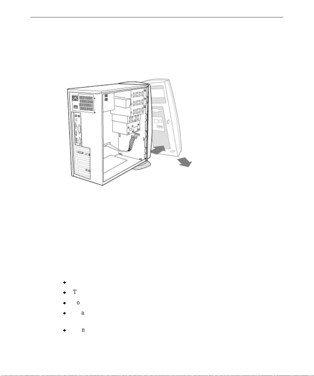
46
To remove the front panel:
1. Disconnect the front panel cable as shown in the following figure.
2. Loosen the tab as shown the following figure.
3. Pull down and out to remove the front panel as shown in the following figure.
CAUTION Place the power and data cables to the side of the fan bracket. This prevents the fan blades
and the processor heat sinks from damaging the cables.
CAUTION While the base unit is open, follow the guidelines in “Taking Antistatic Precautions.”
T aking A ntist atic Precautions
Static electricity can damage the components on an expansion card or the components inside
the base unit. To avoid building up a static charge, do the following:
u
Turn off the power to all devices.
u
To maintain grounding, do not unplug the power cord from the base unit or AC outlet.
u
Touch the bare metal of the base unit chassis to discharge any static electricity.
u
Wear a grounding wrist strap. Ensure the strap is properly connected to the system and to
your wrist.
u
Do not wear wool or polyester clothing.
Page 61

u
Avoid rugs, carpets, and similar surfaces, since they can give you a static charge as you
move on them. Work on a static-safe surface instead.
u
Work in an area with a relative humidity of at least 50 percent.
u
Handle expansion cards as little as possible and by the edges only. Never grab it as you
would a book.
u
Leave new parts in their protective packaging until you install them.
Adding Expansion Cards
You can add Peripheral Component Interconnect (PCI), Plug-n-Play (PnP), and Industry
Standard Architecture (ISA) expansion cards by installing them in the system’s expansion
slots. The following illustrations show the location of the expansion slots on the system
board. Install PnP cards in any expansion slot. The lowest PCI slot and the highest ISA slot
are shared; you can install an expansion card into one or the other, but not both.
NOTE: Plug and Play (PnP) support is not currently available in W i ndows NT.
TD-100
47
PCI
ISA
Page 62

48
Installing Expansion Cards
Follow the steps below to install a new expansion card in an open expansion slot.
To install a new expansion card:
1. Remove the base unit cover as described previously in “Opening the Base Unit.”
TD-100 PII
TD-250
AGP
PCI
ISA
2. Remove the screw securing the blanking plate of an empty expansion slot, and remove the
blanking plate.
3. Insert the expansion card into the expansion slot, using firm and steady pressure.
CAUTION Do not rock or tilt the expansion card. Doing so might damage the card, the slot, or both.
5. Secure the expansion card to the chassis using the screw removed previously.
For more information on installing expansion cards, see Chapter 8, “System Board Overview,”
Chapter 9, “System Board Upgrades,” and the documentation delivered with the expansion
card.
Configuring Expansion Cards
PCI and PnP cards contain configuration registers that define the card to the system
automatically during startup. Older, non-PnP ISA expansion cards do not use configuration
registers, and require configuration before they can be installed. On a system running
Windows 95, the Device Manager handles this. On a system running Windows NT
Workstation 4.0, this may be handled by running a configuration program provided with an
ISA card by its vendor.
NOTE The system’s BIOS contains a built-in configuration menu, so no separate ISA Configuration
Utility (ICU is needed.
Page 63

Adding System Memory
You can add system memory to the computer by adding or replacing Dual Inline Memory
Modules (DIMMs) on the system board. The system board supports the following memory
module sizes, according to system type:
49
Memory Size
DIMM Configuration (non-parity)
16 MB 2 x 64
32 MB 4 x 64
64 MB 8 x 64
When adding or replacing DIMMs:
u
Use 168-pin, 64-bit, 12 ns, unbuffered, double-sided DIMMs with gold-plated contacts.
u
You can add DIMMs one at a time.
u
After adding or replacing DIMMs, restart the computer. The new memory configuration
is detected automatically.
NOTE System memory modules available from Intergraph have been certified for use with Intergraph
computers at extremes of temperature and system load to ensure reliable performance.
System memory modules available from other vendors may function improperly or unreliably
in your Intergraph computer.
The following are common memory configurations:
Memory
Bank 0
DIMMs
Bank 1
DIMMs
Bank 2
DIMMs
16 MB One 16 MB
32 MB One 16 MB One 16 MB
One 32 MB
48 MB One 16 MB One 16 MB One 16 MB
64 MB One 64 MB
One 32 MB One 32 MB
96 MB One 32 MB One 32 MB One 32 MB
192 MB One 64 MB One 64 MB One 64 MB
384 MB One 128 MB One 128 MB One 128 MB
Note Bank 2 and 128 MB DIMMs are used only in the TD-100 PII, TD-250.
Page 64

50
TD-100
DIMM
Sockets
TD-100 PII
TD-250
DIMM
Sockets
To replace system memory:
1. Ensure the pins on the DIMMs match the socket keying.
2. Align pin 1 on the memory module with pin 1 of the socket.
3. Insert the DIMM into the socket at a 90-degree angle. Use even pressure across the top
of the module; then push the module upright until it locks in place.
CAUTION Do not use a rocking motion as you install the memory module. Doing so might damage the
module, the socket, or both.
For more information on system memory, see Chapter 8, “System Board Overview,” and
Chapter 9, “System Board Upgrades.”
Adding Internal Peripheral Devi ces
You can add internal SCSI, IDE, or EIDE peripheral devices by installing them in any
available peripheral bays.
Page 65

The mini-tower system has the following available peripheral bays:
u
Two 5.25-inch x 1.6-inch external-access peripheral bays for devices accessible from
outside the system. The system’s CD-ROM drive occupies one of these bays.
u
One 3.5-inch x 1.0-inch external-access peripheral bay that contains the system’s floppy
disk drive.
u
Two 3.5-inch x 1.0-inch internal peripheral bays for devices not accessible from outside
the system, such as hard disk drives. These bays can support two 1.0-inch high devices.
NOTE The system’s CD-ROM drive is connected to the secondary IDE bus, and is set to be the
master device on that bus. If your system has two internal 3.5-inch IDE or EIDE devices (such
as hard disk drives) installed, and you install a third such device, you must reset the CD-ROM
drive to be the slave device on the secondary IDE bus. For CD-ROM jumper settings, see the
information provided on the CD-ROM drive.
The following illustrations show the location on the system board of the IDE bus connectors
and the power connectors to which you can connect internal peripheral devices.
TD-100
51
IDE
Connectors
TD-100 PII
TD-250
IDE
Connectors
Page 66

52
Opening the Upper 5.25-Inch Peripheral Bay
Unless you purchased your system with two 5.25-inch peripheral devices installed, a plastic
faceplate and a metal blank cover the upper 5.25-inch external-access peripheral bay. Before
you install a second 5.25-inch device, you must remove the plastic faceplate and the metal
blank.
To remove the plastic face plate and the metal blank from the peripheral bay:
1. Remove the front panel as described previously in “Opening the Base Unit.”
2. Press the tabs of the metal blank toward inward, and remove the metal blank.
3. Remove the snap-off plastic faceplate by pulling firmly but gently at its center.
Removing or Replacing Internal 3. 5-Inch Devices
Internal 3.5-inch devices install into the removable drive-mounting bracket, which mounts to
the front of the chassis below the floppy disk drive bay.
To remove or replace internal 3.5-inch devices:
1. Disconnect the data and power cables from any devices already installed in the removable
drive-mounting bracket.
2. Remove the screw securing the drive-mounting bracket to the chassis, and remove the
bracket from the chassis.
3. Remove the four screws securing the devices to the drive-mounting bracket, and remove
the devices.
4. Install the new or additional devices to the drive-mounting bracket.
5. Install the drive-mounting bracket to the chassis. Ensure the lip on the far side of the
bracket engages the appropriate slots in the chassis.
6. Connect the data and power cables to the devices, as appropriate.
For more information on installing an internal peripheral device, see the documentation
delivered with the peripheral device, the information posted on the device, Chapter 8, “System
Board Overview,” Chapter 9, “System Board Upgrades,” and Chapter 10, “BIOS Setup.”
Page 67

7 Using System Resources
This chapter provides information on using system resources, such as interrupt requests
(IRQs) and basic input/output system (BIOS) parameter settings, to configure the system to
use expansion cards. The chapter covers specific Peripheral Component Interconnect (PCI)
and Industry Standard Architecture (ISA) devices offered by Intergraph Computer Systems as
system options. Intergraph Computer Systems has determined that the devices discussed in
this chapter require specific resource settings to ensure proper system operation.
See Chapter 3, “Co nfiguring the System,” for information on running the BIOS Setup program
for your system. See Chapter 10, “BIOS Setup,” for detailed information on the BIOS Setup
program.
System Resources.................................................................................................................... 54
ISA Bus Interrupt Request (IRQ) Assignments......................................................... 54
Direct Memory Access (DMA) Channels................................................................. 54
Input/Output (I/O) Addresses.................................................................................... 54
Using System Resources..........................................................................................................55
53
Page 68

54
System Resources
The following sections list system resources. See the vendor documentation delivered with an
expansion card or a peripheral device for instructions on how to use these resources.
ISA Bus Interrupt Request (IRQ) Assignments
IRQ System Resource IRQ System Resource
0 Reserved (system timer) 8 Real-time clock
1 Reserved (keyboard) 9 Reserved
2 Reserved (interrupt controller) 10 Reserved
3 Serial port COM2 (default) 11 PCI-to-USB controller
4 Serial port COM1 (default) 12 PS/2 mouse
5 Sound processor 13 Reserved (math coprocessor)
6 Floppy disk controller 14 Primary IDE controller
7 Parallel port LPT1 (default) 15 Secondary IDE controller
Direct Memory Access (DMA) Channels
Channel Assignment Channel Assignment
0 Sound processor 4 DMA controller
1 Sound processor 5 Open
2 Floppy disk controller 6 Open
3 Parallel port LPT 1 7 Open
Input/Output (I/O) Addresses
Address (hex) Description
0000 - 000F Direct memory access controller 1
0020 - 0021 Interrupt controller 1
0040 - 0043 System timer
0060 - 0060 Standard 101/102-key keyboard
0061 - 0061 System speaker
0070 - 0071 Real-time clock
00A0 - 00A1 Interrupt controller 2
00C0 - 00DF Direct memory access controller 2
00F0 - 00FF Numeric data processor
Page 69

Address (hex) Description
0120 - 013F PCI-to-USB controller
0170 - 0177 Standard IDE/ESDI hard disk controller
01F0 - 01F7 Primary IDE controller
0201 - 0201 MIDI/game port
0220 - 022F Sound processor
0274 - 0277 ID data read-only port (ISA Plug and Play)
02F8 - 02FF Serial port (COM2)
0330 - 0331 Sound processor
0376 - 0376 Secondary IDE controller
0378 - 037F Parallel port (LPT1)
03F0 - 03F5 Floppy disk drive controller
03F8 - 03FF Serial port (COM1)
03F6 Primary IDE controller
04D0 - 04D1 System board resources
0CF8 - 0CFF PCI bus
55
Using System Resources
Most ISA devices installed in the system require you to reserve an IRQ. PCI devices also
need to use an IRQ, but since they share system resources they can use the same IRQ. At least
one IRQ must be left unassigned, for use with any PCI devices installed in your system.
To reserve an IRQ for an installed device:
1. Restart the system and start the BIOS Setup program.
2. On the Advanced/PCI Configuration screen, select the IRQ you want to reserve.
3. Change the setting for the selected IRQ to Reserved.
4. Save the changes and exit from the BIOS Setup program.
The system has a limited number of open IRQ s. To install more ISA devices than you have
open IRQs, you must disable one unused system port for each excess ISA device, unless the
device does not require an IRQ.
Page 70

56
To disable an unused system port:
1. Restart the system and start the BIOS Setup program.
2. On the Advanced/Peripheral Configuration screen, select the port you want to disable.
3. Change the value of the setting to Disabled.
4. Save the changes and exit from the BIOS Setup program.
The following expansion cards require specific system resource settings, as noted:
Expansion card
Resources required BIOS parameter settings
First modem (Windows NT) COM3, IRQ 4 Disable serial port 1 (COM1)
Second modem (Windows NT) COM2, IRQ 3 Disable serial port 2 (COM2)
First parallel printer adapter Base addr ess 278 None
Second parallel printer adapter Base address 3BC None
On a system running Windows 95, ensure the following system resources are set as noted:
System resource
BIOS Setup parameter settings
Plug and Play operating system Serial port 1, serial port 2, and parallel port enabled; Plug
and Play OS enabled
Serial port 1 (COM1) Reserve IRQ 4 (if port is to be used)
Serial port 2 (COM2) Reserve IRQ 3 (if port is to be used)
Parallel port (LPT1) Reserve IRQ 7 (if port is to be used)
Page 71

8 System Board Overview
This chapter provides a detailed overview of the system board for your TD-100, TD-100 PII,
or TD-250.
Standard Features............................................................................................................. 58
TD-100 System Board ....................................................................................... 58
TD-100 PII, TD-250 System Board................................................................... 59
System Board Map........................................................................................................... 60
TD-100 System Board ....................................................................................... 60
TD-100 PII, TD-250 System Board................................................................... 62
Operating Environment....................................................................................................64
57
Page 72

58
Standard Features
The following sections describe standard features of the system boards.
TD-100 System Board
The system board for the TD-100 features:
♦
Intel Pentium MMX Processor (Socket 7), upgradable to 200 MHz, 233 MHz
♦
Intel 430 TX Chipset, Ball Grid Array (BGA) type
−
82439TX (MTXC)
−
82371AB PCI ISA IDE Accelerator (PIIX4)
♦
System memory up to a maximum of 128 MB using two 64 MB dual inline memory
modules (DIMMs)
♦
External cache memory (L2) available with 512 KB
♦
Phoenix NU BIOS, with Windows 95 Plug and Play support and 2 MB flash ROM for
easy BIOS upgrades
♦
PCI 2.1 compliant PCI/ISA bus architecture
♦
PCI-IDE interface
−
Ultra DMA 33 support
−
DMA Mode 2 Bus Master IDE and PIO Mode 3 and Mode 4
−
ATAPI CD-ROM support
♦
Super I/O chip (SMC FDC37C935APM) for 1 parallel port, 2 serial ports (COM1/2), and
2 PS/2 ports; supports 360 KB, 720 KB, 1.2 MB, 1.44 MB, 2.88 MB floppy disks.
♦
Socket 7 processor support, with a switching power module on board (2.0 V - 3.5 V)
♦
Integrated system power management and full support for ACPI and OS Directed Power
Management
−
CPU stop-clock support
−
Microsoft/Intel APM 1.2 compliant
− Soft-touch power switch
♦ Optional on-board single chip Audio Solution (CS4237) supports ISA Plug and Play
− Supports MPU 401 and Sound Blaster/Sound Blaster Pro
− Supports Microsoft Windows Sound System and 3D effects
Page 73

TD-100 PII, TD-250 System Board
The system board for the TD-100 PII and TD-250 features:
♦
Intel Pentium II (Slot 1) Processor, upgradable through 233 MHz, 266 MHz, 300 MHz,
or 333 MHz
♦
Intel 440 LX Chipset, Ball Grid Array (BGA) type
−
82443LX PCI/AGP Controller (PAC)
−
82371AB PCI ISA IDE Accelerator (PIIX4)
♦
System memory up to a maximum 192 MB using three 64 MB dual inline memory
modules (DIMMs)
♦
Processor available with 512 KB cache memory
♦
Phoenix NU BIOS, with Windows 95 Plug and Play support and 2 MB flash ROM for
easy BIOS upgrades
♦
PCI 2.1 compliant PCI/ISA bus architecture
♦
PCI-IDE interface
−
Ultra DMA 33 support
59
−
DMA Mode 2 Bus Master IDE and PIO Mode 3 and Mode 4
−
ATAPI CD-ROM support
♦
Super I/O chip (SMC FDC37C935APM) for 1 parallel port, 2 serial ports (COM1/2), and
2 PS/2 ports; supports 360 KB, 720 KB, 1.2 MB, 1.44 MB, 2.88 MB floppy disks.
♦
Slot 1 (66 MHz) processor support, with a switching power module on board (2.8 V, 2.9
V, 3.2 V, 3.3 V, 3.5 V)
♦
Integrated system power management and full support for ACPI and OS Directed Power
Management
−
CPU stop-clock support
−
Microsoft/Intel APM 1.2 compliant
−
Soft-touch power switch
♦ Optional on-board single chip Audio Solution (CS4237) supports ISA Plug and Play
(CS4237) or wavetable (ES692S)
− Supports MPU 401 and Sound Blaster/Sound Blaster Pro
− Supports Microsoft Windows Sound System and 3D effects
Page 74

60
System Board Map
The following figures provide a map to the system boards.
TD-100 System Board
Page 75

DIP Switches
61
Key
Name Switch
1 DIP switch 1 CPU Voltage selection
2 DIP switch 2 CPU speed selection
Expansion Slots
Key
Name Slots
3 DIMM sockets 168-pin, 64-bit DIMM sockets
4 ISA slots 98-pin, 16-bit ISA bus expansion slots
5 PCI slots 120-pin, 32-bit PCI bus expansion slots
Connectors
Key
Name Connector
6 PS/2 keyboard PS/2 keyboard (6-pin female)
7 PS/ 2 mouse PS/2 mouse (6-p in female)
8 USB keyboard/mouse Universal Serial Bus (two 4-pin female)
9 Printer LPT parallel port (25-pin female)
10 COM 1, COM 2 COM1, COM 2 serial ports (two 9-pin male)
11 Game/MIDI Joystick, external MIDI (15-pin female)
12 Sound I/O Microphone, Speaker, Line-In
13 PRI IDE Primary IDE (40-pin)
14 SEC IDE Secondary IDE (40-pin)
15 FDD Floppy disk drive (34-pin)
16 POWER System board ATX power supply (20-pin)
17 Reserved
18 FAN Processor cooling fan power lead (2-pin)
19 LED Front LED activity light (6-pin)
20 SPK Speaker output (2-pin)
21 AUDIO 1 Sound connector to modem card (9-pin)
22 AUX 1 Sound connector for auxiliary use (4-pin)
Page 76

62
TD-100 PII, TD-250 System Board
Page 77

DIP Switches
63
Key
Name Switch
1 DIP switch CP U speed selection
Expansion Slots
Key
Name Slot
2 DIMM sockets 168-pin, 64-bit DIMM sockets
3 ISA slots 98-pin, 16-bit ISA bus expansion slots
4 PCI slots 120-pin, 32-bit PCI bus expansion slots
5 AGP slot 124-pin, 32-bit AGP bus expansion slot
Connectors
Key
Name Connector
6 PS/2 keyboard PS/2 keyboard (6-pin female)
7 PS/2 mouse PS/2 mouse (6-pin female)
8USB
Universal Serial Bus (two 4-pin female)
keyboard/mouse
9 Printer LPT parallel port (25-pin female)
10 COM 1, COM 2 COM 1, COM 2 serial ports (two 9-pin male)
11 Game/MIDI Joystick, external MIDI (15-pin female)
12 Sound I/O Microphone, Speaker, Line-In
13 IDE 1 Primary IDE (40-pin)
14 IDE 2 Secondary IDE (40-pin)
15 FDD Floppy disk drive (34-pin)
16 POWER System board ATX power supply (20-pin)
17 Reserved 18 FAN Processor cooling fan power lead (2-pin)
19 FRONT LED Front LED activity light (6-pin)
20 SPKR Speaker output (2-pin)
21 CD Sound connector to CD-ROM drive (4-pin)
22 TV Sound connector to TV card (4-pin)
23 AUX Sound connector for auxiliary use (4-pin)
Page 78

64
Operating Environment
Select the operating envir onment for your system with some thought to its system board. Note
the following:
♦
Keep the system board free from dust, moisture, and direct sunlight.
♦
Keep the system board free from liquid and corrosive chemicals.
♦
Avoid placing the system board near objects that generate a strong electromagnetic field,
such as stereo speakers or speakerphones.
♦
Avoid placing the system board in areas where rapid changes in temperature or humidity
occur, or near sources of temperature changes such as air conditioner vents or heaters.
Page 79

65
9 System Board Upgrades
This chapter provides information you will need to upgrade the system board in your TD-100,
TD-100 PII, or TD-250.
WARNING Make sure that you unplug the power supply when adding or removing a processor, any
expansion cards, or other system components. Failure to do so may cause severe
damage to the system board and its components.
Removing the System Board............................................................................................ 66
Removing or Replacing a Processor................................................................................. 66
TD-100 (Intel Pentium MMX)........................................................................... 67
TD-100 PII, TD-250 (Intel Pentium II)..............................................................68
Setting the Processor Speed ............................................................................................. 70
TD-100............................................................................................................... 71
TD-100 PII, TD-250..........................................................................................73
Main Memory................................................................................................................... 73
Expansion Cards............................................................................................................... 74
External Connectors and Ports......................................................................................... 75
Primary/Secondary IDE connectors................................................................... 75
Floppy Disk Drive Connector............................................................................76
LED Activity Light Connector........................................................................... 76
Cabinet-Mounted Speaker Connector................................................................77
ATX System Board Power Supply Connector................................................... 77
PS/2 Ports........................................................................................................... 78
USB Ports .......................................................................................................... 78
Serial Ports......................................................................................................... 78
Parallel Port........................................................................................................ 78
Game/MIDI Port................................................................................................ 79
Sound I/O Ports.................................................................................................. 79
Page 80

66
Removing the System Board
If you need to remove the system board from the computer, follow these instructions to do so.
WARNING The system board and other computer components contain delicate integrated circuit
chips. To protect the system board and computer components against damage from
static electricity, unplug the computer when working inside it.
WARNING Handle the system board and other computer components as little as possible, and by
the edges only. Do not touch system board components unless instructed. Wear an
antistatic grounding strap when handling the system board or other computer
components.
To remove the system board:
1. Exit or shut down any running programs and the operating system.
2. Turn off power to the system and the monitor.
3. Turn off the power breaker on the back panel of the computer (to the O position).
4. Unplug all connecting cables from external equipment such as the keyboard, the mouse,
the monitor, a printer, speakers, a microphone, peripherals attached to COM ports, and
cables from any installed expansion cards.
5. Open the computer as described in Chapter 6, “Expanding the System.”
6. Remove all the cables connected to the system board, such as cables from the hard disk
drives, the floppy disk drive, and the CD-ROM drive, power cables, LED cables, and so
on.
7. Remove all installed expansion cards from the board, using a screwdriver to loosen the
screw securing the card to the chassis.
8. Using a screwdriver, loosen the screws securing the system board to the chassis, and
carefully remove the system board from the computer.
Removing or Replacing a Processor
If you need to remove or replace the processor (or CPU, for central processing unit), follow
these instructions to do so.
WARNING Make sure that you unplug the power supply when adding or removing a processor, any
expansion cards, or other system components. Failure to do so may cause severe
damage to the system board and its components.
Page 81

TD-100 (Intel Pentium MMX)
The TD-100 uses an Intel MMX processor running at 166 MHz, 200 MHz, or 233 MHz.
To remove the processor:
1. Turn off power to the system.
2. Open the system and, if necessary, remove the system board.
3. Disconnect the processor cooling fan power cable.
4. Press the clip of the heat sink inward and remove the heat sink from the processor.
67
5. Pull the locking lever up and sideways, away from the socket, and remove the processor
from the processor socket.
To replace the processor:
1. Insert the new processor into the processor socket, aligning it as shown in the following
figure.
Page 82

68
2. Close the locking lever.
3. Add the processor heat sink with the cooling fan to the processor.
4. Connect the processor cooling fan power cable.
CAUTION Install the new Pentium MMX processor with the cooling fan. Without a fan circulating air on
the processor and its heat sinks, the processor and/or the heat sinks can overheat and cause
damage to both the processor and the system board.
5. Set the DIP switch to the processor’s speed, as described in “Setting the Pro cessor
Speed.”
TD-100 PII, TD-250 (Intel Pentium II)
The TD-100 uses an Intel Pentium II processor running at 233 MHz, 266 MHz, 300 MHz, or
333 MHz.
To remove the processor:
1. Turn off power to the system.
2. Open the system and, if necessary, remove the system board.
3. Disconnect the processor cooling fan power cable.
Page 83

4. Remove the heat sink support bar.
69
5. Press the two locking tabs inward and lift the processor from the processor socket.
6. Press and lift the “B” part of the push clamp to loosen the heat sink from the processor.
Page 84

70
7. Remove the heat sink from the processor.
To replace the processor:
1. Place the heat sink on the new processor.
2. Press the push clamp to fasten the heat sink to the processor.
3. Insert the processor into the processor socket.
4. Press the two locking tabs outward.
5. Fasten the heat sink support bar until it clicks into place.
6. Connect the processor cooling fan power cable.
CAUTION Install the new Pentium II processor with the cooling fan. Without a fan circulating air on the
processor and its heat sinks, the processor and/or the heat sinks can overheat and cause
damage to both the processor and the system board.
6. Set the DIP switch to the processor’s speed, as described in “Setting the Pro cessor
Speed.”
Setting the Processor Speed
After replacing the processor, make sure to set the DIP switch on the system board correctly to
match the processor’s speed.
Page 85

TD-100
71
The two DIP switches on the system board control the processor voltage and processor speed.
Use a sharp pencil, a pen, or another pointed object to set the individual switches on the two
DIP switches as follows.
DIP Switch 1
CPU Voltage 1 2 3 4 5
2.0 V OFF ON ON ON ON
2.5 V ON OFF ON OFF OFF
2.6 V OFF ON ON OFF OFF
2.7 V ON ON ON OFF OFF
2.8 V OFF OFF OFF ON OFF
2.9 V ON OFF OFF ON OFF
3.0 V OFF ON OFF ON OFF
3.1 V ON ON OFF ON OFF
3.2 V OFF OFF ON ON OFF
3.3 V ON OFF ON ON OFF
3.4 V OFF ON ON ON OFF
3.5 V ONONONONOFF
Page 86

72
DIP Switch 2
CPU Speed 1 2 3 4 5 6
200 MHz OFF ON OFF OFF OFF OFF
233 MHz OFF OFF OFF OFF OFF OFF
Page 87

TD-100 PII, TD-250
The singe DIP switch on the system board controls the processor speed. Use a sharp pencil, a
pen, or another pointed object to set the individual switches on the DIP switch as follows.
CPU Speed 1 2 3 4 5 6
233 MHz ON OFF OFF ON OFF ON
266 MHz OFF ON ON ON OFF ON
300 MHz OFF ON OFF ON OFF ON
333 MHz OFF OFF ON ON OFF ON
73
Main Memory
The system board supports two (TD-100) or three (TD-100 PII, TD-250) banks of main
memory composed of 64 MB dual inline memory modules (DIMMs). Each DIMM socket is
reliable for 8, 16, or 32 Bytes of SDRAM. Total system memory is expandable from 8 MB to
a maximum of 128 MB (TD-100) or 192 MB (TD-100 PII, TD-250).
DIMMs can be inserted into DIMM sockets without regard for order of insertion; the system
board uses auto-bank settings. To properly support the Intel LX chip set and avoid system
problems, use SDRAM memory as specified by the Intel 1.0 Memory Module standard.
To install a DIMM:
1. Read the documentation for the DIMM.
2. Release the white plastic guides on the DIMM socket outward.
Page 88

74
3. The DIMM memory module has two hollows. Align the DIMM with the DIMM socket
and push the DIMM firmly into the socket.
4. Press the DIMM gently until it clicks into place.
Expansion Cards
The system board supports two ISA slots and four PCI slots. On a TD-100 PII or TD-250, the
system board also supports one AGP slot. The system board also uses Plug and Play to assign
IRQs for installed expansion cards, when supported by the operating system.
To install an expansion card:
1. Read the documentation delivered with the expansion card.
2. Remove the screw securing the bracket to the slot you want to use. Keep the screw and
the bracket for future use.
3. Align the card with the slot and insert the card firmly into the slot.
4. Secure the card to the chassis with the screw you removed previously.
Page 89

5. Configure the BIOS to accept the expansion card if necessary. See Chapter 10, “BIOS
Setup,” for more information.
6. Install the necessary driver software for the expansion card.
75
External Connectors and Ports
This section describes the system board’s external connectors and ports.
Primary/Secondary IDE connectors
These connectors support the provided IDE hard disk ribbon cable (40-pin) or CD-ROM drive
ribbon cable.
When connecting a hard disk drive to the system board, after connecting the single end to the
board, connect the two plugs at the other end to the hard disk drive. If you install two hard
disk drives, you must configure the second drive to Slave mode by setting its jumper
accordingly. Please refer to the documentation for the hard disk drive, or to the hard disk
drive’s label, for more information.
When connecting a CD-ROM drive to the system board, connect it to the secondary IDE
connector.
Page 90

76
TD-100
Floppy Disk Drive Connector
The 34-pin ribbon cable from the floppy disk drive connects to the floppy disk drive
connector on the system board. After connecting the single end of the cable to the board,
connect the plug on the other end to the floppy disk drive.
TD-100
LED Activity Light Connector
The 6-pin LED activity light cable connects to the LED activity light connector on the system
board. Any hard disk drive activity, or activity by other devices connected to the
primary/secondary IDE connectors, cause the LED to light.
TD-100 PII, TD-2 50
TD-100 PII, TD-250
Page 91

77
TD-100
TD-100 PII, TD-250
Cabinet-Mounted Speaker Connector
The 2-pin speaker cable connects to the speaker connector on the system board.
TD-100
TD-100 PII, TD-250
ATX System Board Power Supply Connector
The 20-pin ATX power supply cable connects to the ATX power supply connector on the
system board. The plug from the power supply only connects one way.
TD-100
TD-100 PII, TD-250
Page 92

78
PS/2 Ports
These ports support connection of a PS/2 keyboard and a PS/2 mouse. The ports are not
interchangeable, and are labeled accordingly.
USB Ports
These two ports support connection of Universal Serial Bus (USB) devices.
T: Mouse
B: Keyboard
Serial Ports
These two ports support connection of serial communication devices, such as a mouse, an
external modem, or a serial printer.
Parallel Port
This port supports connection of parallel communication devices, such as a printer.
Page 93

Game/MIDI Port
This port supports connection of an analog joystick or an external Musical Instrument Digital
Interface (MIDI) device.
Sound I/O Ports
Three ports support connection of audio devices. The speaker port supports a headphone or an
external speaker with a built-in amplifier. The microphone port supports a microphone. The
line-in port supports auxiliary input from external audio devices.
79
Speaker
Line-In Microphone
Page 94

80
Page 95

10 BIOS Setup
This chapter provides information on using the system’s BIOS Setup program.
Using BIOS Setup............................................................................................................ 82
Entering BIOS Setup........................................................................................................ 82
Navigating BIOS Setup.................................................................................................... 83
BIOS Setup Menus........................................................................................................... 83
Main Menu......................................................................................................... 84
Advanced Menu................................................................................................. 86
Security Menu....................................................................................................87
Power Menu....................................................................................................... 88
Boot Menu ......................................................................................................... 89
Exit Menu...........................................................................................................91
81
Page 96

82
Using BIOS Setup
The system’s BIOS Setup program allows you to configure your computer hardware, and to
set security and power-savings options. The settings you choose are stored in batterymaintained memory (CMOS RAM) that saves the information even when the computer's
power is turned off. When you turn on the computer, it is configured with the values found in
this memory.
Use the BIOS Setup program, if an error has occurred when restarting the system, to
reconfigure the use of the system, or if you encounter problems after changing system features.
Entering BIOS Setup
To enter BIOS Setup:
1. Turn on power to the computer.
2. When prompted, press
F2. The Main menu displays.
Page 97

Navigating BIOS Setup
To navigate the BIOS Setup menu or change BIOS settings, use keyboard keys as follows:
83
Key
F1 Display the General Help window.
ESC Exit the current menu.
← →
↑ ↓
TAB Move the curso r forward through the cells for a highlighted field.
TAB + SHIFT Move the cursor backward through the cells for a highlighted field.
Function
Select the next menu.
Move the cursor up and down between fields
+/- or space bar Scroll forward through the o ptions for the highlighted field.
F9 Set the parameters for the current menu to their default values.
F10 Exit BIOS Setup, setting the parameters for the current menu to their
previous values.
E
NTER Execute commands, or open a submenu that has a plus mark [+] on the left
side of the menu.
NOTE When you highlight a field, information about the field appears on the right side of the screen.
BIOS Setup also provides a General Help window that can be opened from any menu by
pressing
F1.
BIOS Setup Menus
To change a BIOS setting, you must select the appropriate BIOS Setup menu, select the
appropriate field in the menu, and change the setting.
BIOS Setup is composed of six menus:
Menu
Function
Main Configure basic system features
Advanced Configure advanced system features
Security Enable security features and set passwords
Power Savings Configure power-saving system features
Boot Configure the system’s boot order
Exit Save changes and exit from BIOS Setup
Page 98

84
NOTE If your computer will not boot after you have changed settings and exited from BIOS Setup,
reboot and press F2 to reenter BIOS Setup. Once in BIOS Setup, you can try to change the
settings that caused the boot to fail. If problems persist, press
F9 to load the default settings.
Main Menu
When you first enter BIOS Setup, the Main menu appears. You can also select Main from the
menu bar to display the Main menu.
System Time
Sets the hour, minute, and second using a 24-hour clock. Use
TAB to move between the hour,
minute, and second fields. To change the time, use the space bar or number keys.
System Date
Sets the month, day, and year using the space bar to decrease or increase the numbers. Use
TAB to move between the month, day, and year fields.
Legacy Diskette A / Legacy Diskette B
Specifies a drive type for floppy disk drive A or floppy disk drive B. Options are Disabled,
360 KB 5-1/4”, 1.2 MB 5-1/4”, 720 KB 3-1/2”, 1.44 MB 3-1/2”, and 2.88 MB 3-1/2”.
Primary Master / Primary Slave / Secondary Master / Secondary Slave
Your computer can support four IDE drives. All the drivers are detected automatically by the
system BIOS during power-on self-test ( POST). If you want configure the drives manually,
choose the specified drive. Press
ENTER on each parameter for the displayed submenu.
Page 99

85
Setting Description
Type Configures the hard drive type. Use the space bar to select the hard
drive type You can use Auto to let the BIOS automatically select the
drive type.
Cylinders If you select User for the drive type, you can select the number of
cylinders for the hard drive.
Heads Configures the number of read/write heads for the hard drive. Before
you can make changes to this field, the drive type must be set to User.
Sectors Choose the number of sectors per track for the hard drive. Before
you can make changes to this field, the drive type must be set to User.
Maximum Capacity Indicates the capacity of the hard drive.
Multi-Sector Transfers Sets the number of sectors per block to the highest number supported
by the drive.
LBA Mode Control Enables or disables 28-bit addressing of the hard drive, without
regard for cylinders, heads, and sectors.
32 Bit I/O Enables or disables 32-bit input/output (I/O). If the field is disabled
(default), your computer works with 16-bit input and output.
Transfer Mode Selects the method for transferring data between the hard drive and
system memory. The default setting for this field depends on the type
of hard drive installed in your computer.
Ultra DMA Mode Enables the hard drive to use Ultra DMA transfer mode to transfer
data between the drive and system memory.
Memory Cache
Select the external cache memory. Cache memory improves system performance by keeping
frequently used computer instructions in memory with a faster access time than DRAM.
Page 100

86
System Memory
Displays the amount of conventional memory detected by your computer during startup.
Extended Memory
Displays the amount of extended memory detected by the computer during startup.
Advanced Menu
Select Advanced from the menu bar to display the Advanced menu.
Plug & Play O/S
Enables parameters for peripheral ports. Select Yes to use a Plug and Play-capable operating
system. Select No if you need the BIOS to configure non-boot devices. Windows 95
automatically configures the ports regardless of the setting of this field.
Reset Configuration Data
Select Yes to clear system configuration data.
Large Disk Access Mode
Enables the computer’s operating system to work with drives larger than 540 MB. Select DOS
for Microsoft operating systems, or select Other for any other operating system.
 Loading...