


StudioZ
Hardware User’s Guide
May 1998
DHA016340

Copyright
1998 Intergraph Computer Systems. All rights reserved. This document contains information protected by copyright, trade secret, and
trademark law. This document may not, in whole or in part, be reproduced in any form or by any means, or be used to make any
derivative work, without written consent from Intergraph Computer Systems.
Use, duplication, or disclosure by the United States Government is subject to restrictions as set forth in subdivision (c)(1)(ii) of the rights in
technical data and computer software clause at DFARS 252.227-7013. Unpublished rights are reserved under the copyright laws of the
United States.
Intergraph Computer Systems, Huntsville AL 35894-0001
Notice
Information in this document is subject to change without notice and should not be considered a commitment by Intergraph Computer
Systems. Intergraph Computer Systems shall not be liable for technical or editorial errors in, or omissions from, this document. Intergraph
Computer Systems shall not be liable for incidental or consequential damages resulting from the furnishing or use of this document.
All warranties given by Intergraph Computer Systems about equipment or software are set forth in your purchase contract. Nothing stated
in, or implied by, this document or its contents shall be considered or deemed a modification or amendment of such warranties.
Trademarks
Intergraph Computer Systems and the Intergraph Computer Systems logo are registered trademarks of Intergraph Computer Systems.
StudioZ and StudioZ TD are trademarks of Intergraph Computer Systems.
Microsoft, Windows, and the Microsoft logo are registered trademarks of Microsoft Corporation. Windows NT is a trademark of
Microsoft Corporation. Softimage is a registered trademark of Softimage, a wholly-owned subsidiary of Microsoft Coporation.
SwitchBack and Apex are trademarks of Apex PC Solutions Incorporated. WACOM is a trademark of WACOM Co., Ltd. Serial Box is a
trademark of Ensemble Designs, Inc. InstallShield is a registered trademark of InstallShield Corporation, a business unit of Stirling
Technologies, Inc.
Other brands and product names are trademarks of their respective owners.
FCC/DOC Compliance
This equipment has been tested and found to comply with the limits for a Class A digital device, pursuant to part 15 of the FCC Rules.
These limits are designed to provide reasonable protection against harmful interference when the equipment is operated in a commercial
environment. This equipment generates, uses, and can radiate radio frequency energy. If the equipment is not installed and used in
accordance with the instruction manual, it may cause harmful interference to radio communications.
Operation of this equipment in a residential area is likely to cause harmful interference in which case the user will be required to correct the
interference at his own expense.
Changes or modifications made to the system that are not approved by the party responsible for compliance could void the user’s authority
to operate the equipment.
This Class A digital apparatus meets all requirements of the Canadian Interference-Causing Equipment Regulations. Cet appareil
numérique de la classe A respecte toutes les exigencies du Règlement sur le materiél brouilleur du Canada.
Warnings
Changes or modifications made to the system that are not approved by the party responsible for compliance could void the user's authority
to operate the equipment.
To reduce the risk of electrical shock, do not attempt to open the equipment unless instructed. Do not use a tool for purposes other than
instructed.

Notes
This device is designed and manufactured to comply with approved safety standards for information processing and business equipment.
Read all operating instructions before using this device. Keep these instructions for future reference. Follow all warnings on the device or
in the operating instructions.


Contents
Preface.............................................................................................................................. vii
About This Document........................................................................................................vii
Document Conventions.....................................................................................................viii
Operating System Information ..........................................................................................viii
Hardware Information....................................................................................................... viii
Additional StudioZ Information........................................................................................ viii
Ergonomic Information.......................................................................................................ix
Customer Support............................................................................................................... ix
1 Getting Started................................................................................................................ 1
Setting up the StudioZ Workstation ..................................................................................... 1
Installing the StudioZ Driver ............................................................................................... 3
Configuring the Workstation’s Video Display.................................................................... 10
Connecting to the StudioZ SDI Board................................................................................ 10
v
Hardware and Software Support Services.............................................................. ix
World Wide Web.................................................................................................. ix
Intergraph Bulletin Board Service ......................................................................... ix
FAXLink................................................................................................................ x
Telephone .............................................................................................................. x
More Support Options...........................................................................................xi
Installing the StudioZ SDI Hardware...................................................................... 2
Stopping the Current Driver ................................................................................... 3
Loading and Starting the New Driver ..................................................................... 4
Configuring the StudioZ Driver..............................................................................5
Cables and Connections ....................................................................................... 10
Connecting a Video Monitor ................................................................................ 11
Connecting a VTR ............................................................................................... 13
2 Understanding StudioZ SDI Functionality................................................................... 17
StudioZ SDI Functional Description .................................................................................. 17
Uncompressed Capture and Playback................................................................... 17
JPEG Compression/Decompression...................................................................... 18
Video I/O............................................................................................................. 18
Video Input/Output Interface Specifications....................................................................... 19
Composite Video Output...................................................................................... 19
S-video Output..................................................................................................... 19
SDI Video Input/Output ....................................................................................... 19
Real-Time Video Capture .................................................................................................. 20
Real-Time Video Playback................................................................................................. 20

vi
3 Capturing and Playing Back Video.............................................................................. 21
Video Capture.................................................................................................................... 21
Managing the Video Digitizing Process................................................................ 21
Managing the Video Data Rate............................................................................. 21
Video Playback.................................................................................................................. 23
4 System-Specific Information......................................................................................... 25
StudioZ for SOFTIMAGE|DS............................................................................................25
Flashkey............................................................................................................... 25
Setting Up a Stripe Set ......................................................................................... 25
Configuring the Adaptec BIOS Settings ............................................................... 28
StudioZ Pro and StudioZ T-RAX....................................................................................... 29
Installing the Driver for an Additional Adaptec Controller ................................... 29
Setting Up a Stripe Set ......................................................................................... 30
A StudioZ Options............................................................................................................ 31
Pre-installation Instructions for Sportster 56K Voice Internal U.S. Robotics Modem.......... 31
Calibrating the Ensemble A/D Converter ........................................................................... 34
Positioning the WACOM Tablet During Capture ............................................................... 34
Apex Switchback Extender................................................................................................ 34
Configuring the Audio Storage Option............................................................................... 36
Professional Audio Option Antex Studio Card ................................................................... 36
Backup Storage Options..................................................................................................... 37
Video Storage Options....................................................................................................... 37
InterRAID-8e StudioZ Video Storage Option....................................................... 37
Setting up the IR-8e ............................................................................................. 38
Disabling the IR-8e Alarm ................................................................................... 39
Installing the Deskside Foot ................................................................................. 40
Reorienting the IR-8e ICP.................................................................................... 40
StudioZ for SOFTIMAGE|DS IR-8e Stripe Setup.................................................42
StudioZ T-RAX and StudioZ Pro IR-8e Stripe Setup............................................ 43
B Troubleshooting StudioZ Operation............................................................................ 45
Index................................................................................................................................. 49

Preface
The StudioZ Hardware User’s Guide describes how to set up the StudioZ workstation.
Intergraph Computer Systems’ StudioZ workstations provide a complete video solution,
allowing you to capture, edit, and play back real-time video and animated computer
graphics.
StudioZ combines Joint Photographic Experts Group (JPEG) compression/decompression
circuitry with a serial digital video interface (SDI, also known as DI) on a single PCI board.
StudioZ relies on your workstation’s audio processor and Windows NT multimedia tools for
audio capability.
StudioZ audio/video operations allow you to:
u
u
u
u
StudioZ is designed for use with audio and video editing software products that run under
the Windows NT operating system.
vii
Capture video and audio to hard disk with or without video compression.
Play back audio and video from hard disk with or without video compression.
Compress and decompress images (via hardware) as part of the editing process.
Convert sequences of uncompressed still images to full-motion format for editing and
real-time playback.
About This Document
The StudioZ Hardware User’s Guide is organized as follows:
u
Chapter 1, “Getting Started,” describes how to set up your StudioZ workstation
hardware and driver software, and connect to various types of video equipment.
u
Chapter 2, “Understanding StudioZ SDI Functionality,” describes the real-time video
capture and playback capabilities, and image compression and decompression.
u
Chapter 3, “Capturing and Playing Back Video,” describes how to obtain high-quality
video results using StudioZ.
u
Chapter 4, “System-Specific Information,” provides further configuration instructions
for your StudioZ workstation.
u
Appendix A, “StudioZ Options,” provides information and setup instructions for the
many options available for your StudioZ workstation.
u
Appendix B, “Troubleshooting StudioZ Operation,” describes problems you could
encounter and provides tips for solving them.

viii
Document Conventions
Bold
Italic Variable values that you supply, or cross-references.
Monospace
SMALL CAPS Key names on the keyboard, such as D, ALT or F3; names of files and directories.
CTRL+D Press a key while simultaneously pressing another key; for example, press CTRL
Commands, words, or characters that you key in literally.
Output displayed on the screen.
You can type filenames and directory names in the dialog boxes or the command
line in lowercase unless directed otherwise.
and D simultaneously.
Operating System Information
For more detailed information on the operating system, refer to the printed and online
Microsoft documentation delivered with the workstation.
Hardware Information
The StudioZ workstation includes an Intergraph Computer Systems workstation base. For
detailed information on setting up, opening, maintaining, or upgrading your Intergraph
Computer Systems workstation base, refer to the printed and online Intergraph
documentation delivered with the workstation.
Additional StudioZ Information
Additional StudioZ information is available in StudioZ Starts Here! This document contains
important information that may not have been available at the press time of the StudioZ
Hardware User’s Guide, and is delivered with your workstation.
Ergonomic Information
Read the Ergonomics Guide delivered with your workstation for valuable information on
ways to minimize repetitive stress injuries when working with a computer.

Customer Support
Intergraph Computer Systems offers an assortment of customer support options.
Hardware and Software Support Services
Intergraph Computer Systems provides a variety of hardware services for Intergraph and
third-party equipment. Services include warranty upgrades, repair depot service, on-site
hardware maintenance, system administration, and network consulting. Hardware
purchased from Intergraph Computer Systems includes a factory warranty ranging from 30
days to three years. A detailed warranty description is available on the World Wide Web;
see the Support pages at http://www.intergraph.com/ics.
Intergraph Computer Systems provides complimentary software support for 30 or 90 days
following shipment of a hardware or software product. This includes World Wide Web
access, Intergraph Bulletin Board Service access, FAXLink service, and telephone (Help
Desk) support. At the end of the complimentary support period, you can purchase other
levels of software support.
World Wide Web
ix
You can visit Intergraph Computer Systems on the World Wide Web at
http://www.intergraph.com/ics. On these pages, you can get news and product
information, technical support information, software updates and fixes, and more.
Intergraph Bulletin Board Service
On the Intergraph Bulletin Board Service (IBBS), you can get technical support information,
software updates and fixes, and more.
To connect to the IBBS:
1. Set your system’s communications protocol for eight (8) data bits, no parity, one (1) stop
bit, and any baud rate up to 14,400.
2. Using a modem, call 1-205-730-8786. Outside the United States, call one of the mirror
sites listed on World Wide Web; see the Software Support pages at
http://www.intergraph.com.
3. At the login prompt, key in your user ID. If you have not connected before, key in new
to create a user ID.
4. Follow the menus to find what you need. The IBBS provides clear choices and online
help.

x
If you have trouble connecting to or using the IBBS, call the Customer Response Center at
1-800-633-7248 (product entry IBBS) or leave a message for the IBBS System Operator at
1-205-730-1413.
FAXLink
To use the FAXLink:
u
u
Telephone
To get customer support by telephone:
u
u
Call 1-800-240-4300 for information on how to get technical support information using
the FAXLink.
Call 1-205-730-9000 to get documents (up to five per call).
In the United States, call 1-800-633-7248 between the hours of 7:00 a.m. and 7:00
p.m. Central Time, Monday through Friday (except holidays).
Outside the United States, contact your local Intergraph Computer Systems subsidiary or
distributor.
Have the following information available when you call:
u
Your service number, which identifies your site to Intergraph Computer Systems. You
use your service number for warranty or maintenance calls.
u
Your Customer Personal Identification Number (CPIN). You get a CPIN the first time
you call the Customer Response Center; it is associated with your service number for
future call logging.
u
The product’s name or model number.
u
The product’s serial number. Software product serial numbers are included in the
product packaging. Hardware product serial numbers are on a sticker affixed to the
hardware product.
u
Your name and telephone number.
u
A brief description of the question or problem.

More Support Options
To get information on more customer support options:
u
Visit the Support pages on the World Wide Web at http://www.intergraph.com/ics.
u
For hardware support questions in the United States, call 1-800-763-0242.
u
For software support questions in the United States, call 1-800-345-4856.
Outside the United States, contact your local Intergraph Computer Systems subsidiary or
distributor.
xi

xii

1 Getting Started
This chapter describes how to install and configure the StudioZ SDI hardware and driver
software, and connect your StudioZ workstation to various types of video equipment.
Setting up the StudioZ Workstation
If you purchased a complete StudioZ workstation, it was shipped ready for you to set up and
begin work.
To set up the StudioZ workstation:
1. Refer to the hardware user documentation delivered with the workstation to set up
hardware and configure the Windows NT operating system.
2. Go to “Installing the StudioZ Driver” in this chapter to load, start, and configure the
latest StudioZ driver.
3. Go to “Configuring the Workstation’s Video Display” in this chapter for tips on
optimizing video output on the workstation’s monitor.
1
4. Go to “Connecting to the StudioZ SDI Board” in this chapter to connect your video
equipment to the StudioZ SDI board.
If you have to replace the StudioZ SDI board or reinstall the StudioZ driver software:
1. Go to “Installing the StudioZ SDI Hardware” in this chapter to install the StudioZ SDI
board.
2. Go to “Installing the StudioZ Driver” in this chapter to install, start, and configure the
StudioZ driver.
3. Go to “Configuring the Workstation’s Video Display” in this chapter for tips on
optimizing video output on the workstation’s monitor.
4. Go to “Connecting to the StudioZ SDI Board” in this chapter to connect your video
equipment to the StudioZ SDI board.

2
Installing the StudioZ SDI Hardware
Your StudioZ workstation is delivered with a StudioZ SDI board in a primary PCI expansion
slot. Do not move the card from this slot. Primary slot assignments are as follows:
u
TD desktop workstation — all PCI slots
u
TD deskside workstation — slots 5 and 6
If you need to replace the StudioZ SDI board, remove the existing board and install the new
one in the same PCI expansion slot from which you removed the old one.
Workstation type
PCI expansion slots
Desktop 1, 2, 3
Deskside 5, 6
Rack-mount 5, 6
To install the StudioZ SDI hardware:
1. Shut down power to the workstation.
2. Open the base unit.
3. Remove the old StudioZ SDI board from its PCI slot, as appropriate.
4. Insert the new StudioZ SDI board in the slot and secure it to the chassis with a screw.
5. Close the base unit.
6. Restart the workstation.

Installing the StudioZ Driver
Depending on which board you have, you may need to upgrade the StudioZ driver. You can
obtain the latest driver from the diskette delivered with your workstation, from the Support
pages on the Intergraph Computer Systems World Wide Web site, or from the Intergraph
Bulletin Board Service (IBBS) File Libraries. See the Preface for more information on the
Support pages and the IBBS. See “Loading and Starting the New Driver” in this chapter for
instructions on getting the driver.
There are two StudioZ drivers. The following table specifies which driver you need
according to the StudioZ workstation you purchased:
3
If you have this workstation
StudioZ Solo, Duo, or Quattro STUDIOZ.ZIP (this is the StudioZ driver)
StudioZ T-RAX STUDIOZ.ZIP
StudioZ Pro STUDIOZ.ZIP
StudioZ for SOFTIMAGE|DS STUDIO~1.ZIP (this is the StudioZBurst driver)
Select this ZIP file
Stopping the Current Driver
You must stop your current driver before you load the new one.
To stop the current driver:
1. From the Windows NT Start menu, go to Control Panel/Devices.
2. Scroll down the Device list and select the Intergraph StudioZ driver.
NOTE Depending on your workstation, the Device list will display either “Intergraph StudioZ Driver”
or “Intergraph StudioZBurst Driver.” See the table above for a list of workstations and
drivers.
3. Click Stop.
4. Click Close to dismiss the Devices dialog box.

4
Loading and Starting the New Driver
If you are installing the driver from the diskette delivered with your workstation, insert the
diskette into the floppy disk drive. In Explorer, select the floppy disk drive (usually drive
A:\), and double-click
displays, skip to step 6 of the following instructions.
To load and start the new driver:
1. Using your Web browser, go to the Support pages on Intergraph Computer Systems
World Wide Web site (http://www.intergraph.com/ics), or to the IBBS File Libraries
page (http://archive.intergraph.com/bbs/ibbsfile.htm).
2. On the Support pages, search for graphics drivers for all systems. On the IBBS File
Libraries page, scroll down the list and select DIGSWH to open the Digital Media
StudioZ Driver page.
SETUP.EXE from the diskette. When the InstallShield setup wizard
3. Select either
STUDIOZ.ZIP (the Intergraph StudioZ driver) or STUDIO~1.ZIP (the
Intergraph StudioZBurst driver). The necessary files are downloaded to a temporary
folder on your workstation. When the transfer is complete, WinZip displays the
contents of the
ZIP file.
4. In WinZip, click Extract and place all of the files in a directory on your machine (for
example, C:\
NOTE See the WinZip Help File if you need information on extracting files. From the WinZip Help
menu, select Search for Help on... and type extract in the first field of the Index tab. Select a
topic from the index entries and click Display.
TEMP).
5. In Explorer, move to the directory where you extracted the files and double-click the
SETUP.EXE file. The InstallShield setup wizard displays.
6. Follow the prompts to install the driver. See the
README.TXT file delivered with the
driver if you need more information.
NOTE If you select the wrong driver, a warning message will notify you that the driver could not be
started. If this happens, go back to the diskette or your web browser and select the other
file.
7. When you see a notification that the installation is complete, go back to Control
Panel/Devices.
8. Scroll down the list of devices to the Intergraph StudioZ Driver or the Intergraph
StudioZBurst Driver and verify that it is started (the word “Started” should appear under
the Status column).
ZIP
9. If the device is not started, select the driver and click Start.
10. Click Close to dismiss the Devices dialog box.

Configuring the StudioZ Driver
Once the driver is installed and started, you can change the configurations to meet your
specific needs.
To configure the StudioZ driver:
1. Close any applications that rely on the StudioZ driver (such as StudioZ Central Plus or
Adobe Premiere).
NOTE Adjustments you make to the StudioZ driver configuration, particularly the Genlock Phase
Adjust parameter, will not take effect when the driver is under an application’s control. When
you restart the application, changes you made to the StudioZ driver configuration will take
effect.
2. From the Windows NT Start menu, go to Control Panel/Multimedia.
3. On the Multimedia Properties dialog box, click the Devices tab, then double-click Video
Compression Codecs from the list of devices.
4. Double-click Intergraph StudioZ Driver (or Intergraph StudioZBurst Driver) from the
list of video compression codecs.
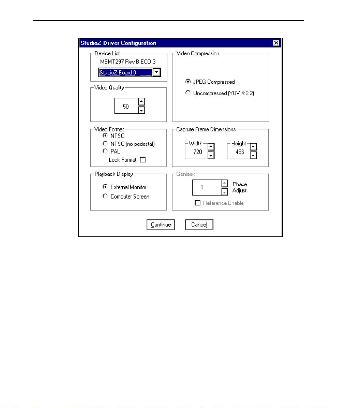
5. On the Intergraph StudioZ Driver Properties tab, click Settings to display the StudioZ
Driver Configuration parameters:
5
6
6. Change the parameters as necessary to configure the driver for use in your environment.
(See the following table for a description of each setting.)
7. Click Continue to accept the new settings and dismiss the dialog box.
8. Click Close in the Drivers dialog box, then dismiss the Control Panel.
The changes take effect the next time you run the StudioZ utilities. See Chapter 2,
“Understanding StudioZ SDI Functionality,” for information about StudioZ operations.

StudioZ Driver Configuration Parameters
7
Parameter
Description
Device List Displays the boards detected by the StudioZ driver.
Video Quality Specifies the video quality value. Video quality is related to the
amount of video compression — a higher value results in less
compression. Higher values result in better quality video that
requires a lot of disk space. Lower values use a higher
compression rate. This produces lower-quality video that
requires less disk space.
Recommended video quality settings:
Betacam SP, 98
S-Video, 91 to 98
DigiBeta, 98
Video Format Specifies the video display standard. Select the format that is
compatible with your external video source format. Also, use
the same format for both video capture and playback.
Otherwise, you could encounter problems such as poor image
quality, bad colors, or a blank screen.
Click either NTSC, NTSC (no pedestal), or PAL, depending on
your requirements.
NTSC Specifies that the National Television Standards Committee
(NTSC) format of 525 lines (486 visible), 29.97 frames/second
is the video display standard. NTSC is widely used in the
United States. This format has a pedestal that raises the black
to 7.5 IRE.
NOTE The relative amplitudes of television signal
components are measured by a linear scale made
up of IRE units. The zero reference, or 0 IRE, is
the blanking level of this scale.
NTSC (no pedestal) Specifies the NTSC format in terms of lines and frames per
second. The difference between NTSC (no pedestal) and NTSC
is that black is at the blanking level (0 IRE). NTSC (no
blanking) is used mainly in Japan.
PAL Specifies that the Phase Alternate Line (PAL) format of 625
lines (576 visible), 25 frames/second is the video display
standard. PAL is widely used in Europe.

8
StudioZ Driver Configuration Parameters, cont.
Lock Format Specifies that the external monitor format matches the video
format specified in the StudioZ Driver Configuration dialog
box, and is not affected by video format changes in any
application or the format of the AVI being played back.
When Lock Format is selected, you must play back video that
was captured in the same format as the one specified here
(either NTSC or PAL). If you try to play back a video sequence
that was captured in a format other than the one specified, the
video sequence could play back at the wrong speed and the
audio will be out of sync.
In most cases, you must close any application that relies on the
StudioZ driver before changing the driver configurations.
However, SOFTIMAGE|DS and StudioZ Central Plus let you
change the video format from within the application, provided
Lock Format is turned off. This lets you play both NTSC- and
PAL-formatted clips correctly without having to close the
application and modify the StudioZ driver configurations. This
is useful if you regularly work with both NTSC and PAL
formats.
NOTE Lock format should always be turned off for
SOFTIMAGE|DS and StudioZ Central Plus,
regardless of whether you always use one format
or swap between NTSC and PAL. See the
documentation supplied with those applications for
information on specifying NTSC or PAL from
within the application.
NOTE If you use Adobe Premiere, make sure that Lock
Format is turned on. If it is turned off, you will not
be able to scrub frames correctly on the video
timeline.
Playback Display Specifies the video output display device. Select either External
Monitor or Computer Screen.
External Monitor Specifies that the output display device is the external video
monitor connected to the StudioZ board. This setting provides
the best video quality and performance, and is the default.
Computer Screen Specifies that the video output display devices is the monitor
connected to your workstation. You should use the computer
screen only as a diagnostic tool.
Video Compression Specifies the type of compression applied to the captured frame.

StudioZ Driver Configuration Parameters, cont.
JPEG Compressed Provides the optimum data rate using compressed capture.
9
Uncompressed
(YUV 4:2:2)
Specifies that the luminance and chrominance values are
obtained during a capture, and does not apply any compression
to the captured data. See Chapter 3, “Capturing and Playing
Back Video,” for more information.
Capture Frame Dimensions Specifies the size at which frames are captured. Video data is
normally captured at full frame sizes, which are 720 x 486 for
NTSC (525 line, 59.94 Hz) and 720 x 576 for PAL (625 line,
50 Hz). You can resample video data on capture to lower
resolutions or square pixel sizes to meet your requirements. See
Chapter 3, “Capturing and Playing Back Video,” for more
information.
NOTE For compressed capture, the width and height
must be a multiple of 16 (with the exception of
720 x 486).
NOTE For uncompressed capture, the width and height
must be a multiple of 2.
Width Specifies the horizontal size of captured frames.
Height Specifies the vertical size of captured frames.
Genlock Synchronizes the video output signal with the reference signal
input (also known as house sync).
NOTE The genlock parameters are disabled if you do not
have an MSMT383 (or later) board.
Phase Adjust Allows you to fine-tune the synchronization of the subcarrier
output timing. Use the scroll arrows to change the phase adjust
value.
Reference Enable Allows the StudioZ SDI card to use either an internal or an
external genlock source.
NOTE Reference Enable is on by default if you loaded the
Intergraph StudioZBurst driver. If you do not have
a house sync, Reference Enable will cause sync,
color, and scrolling problems in your external
monitor. To prevent these problems, make sure
Reference Enable is turned off if you do not have a
house sync.
Continue Accepts the settings and returns you to the Drivers dialog box.
Close Dismisses the dialog box without accepting any changes to the
driver configuration.

10
Configuring the Workstation’s Video Display
To optimize the graphics display on the workstation monitor, do the following when
configuring the workstation’s video display:
u
Select a resolution greater than 720 x 576 to accommodate full-size images for either
NTSC or PAL.
u
Select a resolution that provides square pixels. These include 800 x 600, 1024 x 768,
1280 x 960, 1600 x 1200, and any other resolution with a 4:3 aspect ratio. Adjust the
monitor display to create borders of equal width.
If the resolution is 1280 x 1024, or any other resolution with a 5:4 aspect ratio, adjust
the vertical borders to be wider than the horizontal borders.
NOTE StudioZ for SOFTIMAGE|DS can only use a 1280 x 1024 graphics display resolution with
60Hz refresh rate and 16.7M colors.
u
Select a resolution that allows for the maximum number of colors possible.
Refer to the printed and online Intergraph documentation delivered with the workstation for
instructions on configuring the video display.
Connecting to the StudioZ SDI Board
This chapter provides an overview of the cables and connections for the StudioZ SDI board,
and describes how to connect StudioZ to various types of video equipment.
Cables and Connections
General cable recommendations are as follows:
S-video or Y/C cables Use high-performance cables. Gold Series are
commercially available through local audio/video
suppliers.
Coax cables (BNC to BNC) Use high-quality 75 ohm coaxial cables. If needed,
cables and adapters (BNC to RCA, etc.), are
commercially available through local audio/video
suppliers and general electronics suppliers.
CAUTION Adapter use is a potential source of signal degradation. If you must use adapters, use only
high-quality, tight-fitting adapters.

The video input/output (I/O) connectors include 75-ohm BNC connectors for SDI and
reference signal input, and SDI and Composite output. A 4-pin mini-DIN port is included
for S-video output. Refer to the following figure:
11
Video input and output are connected to the StudioZ workstation through ports on the
StudioZ SDI board.
Connections
Input
Output
Signal Description
SDI 75-ohm BNC coax connector
Reference Signal 75-ohm BNC coax connector
S-video 4-pin mini-DIN connector
Composite 75-ohm BNC coax connector
SDI 75-ohm BNC coax connector
Connecting a Video Monitor
Connect your video monitor to the StudioZ SDI board using the recommended cables (see
the tables earlier in this chapter). Place the video monitor and the computer monitor at least
one foot apart to avoid synchronization interference.
The following instructions are guidelines for connecting your equipment. Refer to the
documentation delivered with your video monitor for detailed information on the ports to
which you should connect the SDI board.

12
C
To connect a video monitor to the StudioZ SDI board:
Connect your video monitor to the SDI board using one of the following methods:
−
Connect S-video (Y/C OUT) on the SDI board to Line C IN (Y/C IN) on your video
monitor.
−
Connect COMP OUT (composite video output) on the SDI board to either Line A or
Line B Video IN (composite video input) on your video monitor.
−
Connect SDI OUT on the SDI board to Component SDI IN on your video monitor
(this is applicable only if your video monitor has Component SDI IN and SDI
OUT).
Y C OUT
StudioZ Interface
COMP OUT
SDI IN
SDI O UT
REF IN
Video
Out
SDI, S-video, Y/
or Composite
Video Cable
Video Monitor
Rear Connector
Panel
Video In

Connecting a VTR
Connect your video tape recorder (VTR) to your StudioZ workstation using the
recommended cables (see the tables earlier in this chapter).
The following instructions are guidelines for connecting your equipment. Refer to the
documentation delivered with your VTR for detailed information on the ports to which you
should connect the SDI board.
To connect a VTR to the StudioZ SDI board:
1. Connect your VTR input to the SDI board using one of the following methods:
−
Connect S-video (Y/C OUT) on the SDI board to S-video IN (Y/C IN) on your
VTR.
−
Connect COMP OUT (composite video output) on the SDI board to COMP IN
(composite video input) on your VTR.
−
Connect SDI OUT on the SDI board to Component SDI IN on your VTR (this is
applicable only if your VTR has Component SDI IN).
NOTE You must have a converter box (such as the Ensemble converter) in order to capture in S-
video, composite, or component analog mode. See Chapter 5, “StudioZ Options,” for more
information on the Ensemble converter.
13
2. Connect your VTR output to the SDI board using one of the following methods:
−
Connect S-video (Y/C OUT) from the VTR to S-video IN (Y/C IN) on the
converter, then connect SDI OUT from the converter to SDI IN on the StudioZ SDI
board.
−
Connect COMP OUT (composite video output) on the VTR to COMP IN
(composite video input) on the converter, then connect SDI OUT from the converter
to SDI IN on the StudioZ SDI board.
−
Connect YUV VIDEO OUT (component analog video output) on the VTR to YUV
VIDEO IN (component analog video input) on the converter, then connect SDI
OUT from the converter to SDI IN on the StudioZ SDI board.
−
Connect SDI OUT from the digital deck to SDI IN on the SDI board (this is
applicable only if you have a digital deck such as the DigiBeta deck).

14
SDI IN
SDI OUT
REF IN
COMP OUT
Y C OUT
Video In
SDI, S-video,
or Composite
Video Cables
Video Out
Video Out
StudioZ Interface
Video In
Video
Out
VTR
Optional
SDI
Converter
SDI
In
Video Monitor
Rear Connector
Panel
NOTE Refer to your video monitor documentation for information on which ports to connect to for
the type of video you are using.

If your VTR has stereo audio capability, refer to the following figure to connect the VTR
audio inputs and outputs to your StudioZ workstation. Use two stereo miniphone-to-RCA
phono cables (user supplied), and one stereo splitter cable (user supplied).
NOTE The Line In and Line Out ports are located on the back panel of the workstation’s base unit.
15
Stereo
Splitter
Cable
To
Speakers
Line In
VTR
Audio Out
Audio In
Line Ou t
Stereo MiniPhone to RCA
Phono Cables

16

2 Understanding StudioZ SDI Functionality
With StudioZ SDI, you have the capability for real-time audio/video capture and playback.
StudioZ SDI is designed to work with audio/video editing software products running under
the Windows NT operating system.
StudioZ SDI Functional Description
StudioZ SDI provides these basic capabilities:
u
Capture of video and audio to hard disk.
u
Playback of compressed and uncompressed video and audio from hard disk.
u
Hardware image compression and decompression to and from host memory.
StudioZ SDI includes JPEG Compression/Decompression circuitry, video input/output (I/O),
and the StudioZ Central Plus application software. See the StudioZ Central Plus Quick-Start
Guide and StudioZ Central Plus Online Reference Guide for more information.
17
StudioZ Central Plus is an individual program, although it also may be integrated into other
software packages. Check with Intergraph Computer Systems support if you have any
questions about integrating StudioZ Central Plus into other packages. See the Preface for
more information on customer support.
NOTE The SDI board in StudioZ Pro relies on the workstation’s audio processor for audio capability.
The SDI board in StudioZ T-RAX and StudioZ for SOFTIMAGE|DS relies on a separate
professional audio card. See Appendix A, “StudioZ Options,” for more information.
Uncompressed Capture and Playback
The StudioZ Pro, StudioZ T-RAX, and StudioZ for SOFTIMAGE|DS SDI board is capable
of capturing and playing back uncompressed video at full size and full rate. In this mode,
the compression setting or Video Quality level is ignored. During video capture, the
compression circuitry is bypassed and the uncompressed video is transferred to system
memory. From there it is written to the disk. During playback the process is reversed —
again bypassing the decompression circuitry.
You can vary the size, brightness, contrast, hue, and saturation of the video as it is captured
or played back in either compressed or uncompressed mode. You also can build video
sequences from bitmaps generated by other applications.

18
JPEG Compression/Decompression
StudioZ SDI can capture and play back full-rate, full-frame video while performing
hardware-accelerated motion JPEG compression and decompression. As video frames are
digitized, they may be JPEG compressed, written to system memory, and then written to hard
disk. This compression reduces the disk data rate required for full-rate, full-frame capture.
The actual disk data rate is a function of the Video Quality value set during StudioZ driver
configuration, the image content of the video captured, and the amount of hard disk space
that is used.
NOTE See “Configuring the StudioZ Driver” in Chapter 1 for information about setting the Value
Quality.
Motion JPEG encoding is an intraframe compression scheme. Each field is compressed
individually, allowing frame boundary editing at any point in the video. The reconstructed
JPEG image is not a bit-for-bit copy of the original image. You can adjust the image quality
by changing the Video Quality value during StudioZ driver configuration.
NOTE You can also adjust the Video Quality value in StudioZ Central Plus. See the
Plus Quick-Start Guide
You can compress images (raster data blocks) in system memory and then store them in
system memory. You can also decompress compressed images, with system memory serving
as both the source and destination. With the exception of 720 x 486, images must be
composed of an integer multiple of 16 x 16 pixel blocks.
StudioZ provides DMA capability to allow compression and decompression to occur with
minimal host processor intervention.
for more information.
Video I/O
StudioZ accepts SDI input in either 525 line/59.94 Hz (NTSC) or 625 line/50 Hz (PAL)
format. The 10-bit-per-component input is processed by input lookup tables for 10-bit-percomponent to 8-bit-per-component transformation, and for brightness, contrast, hue, and
saturation adjustment.
The StudioZ video encoder takes digital YUV 4:2:2 data and produces SDI, S-video, and
composite outputs in either 525/59.94 Hz or 625/50 Hz formats. Lookup tables convert 8bit-per-component output data to 10-bit-per-component output data and can provide
brightness, contrast, hue, and saturation adjustment.
StudioZ Central

Video Input/Output Interface Specifications
The specifications for the video I/O connections are provided below.
Composite Video Output
Output Connection Signal Level
Composite video BNC coax cable 1V p-p into 75 ohms
S-video Output
Pin Signal Signal Level
1 Y + Sync 1V p-p into 75 ohms
2 Chroma 1V p-p into 75 ohms
3 Ground
4 Ground
SDI Video Input/Output
19
Output Connection Signal Level
SMPTE 259M video BNC coax cable 1V p-p into 75 ohms
Real-Time Video Capture
The video data are received from the external video source (SDI Input) as fields of 243
(for 525/59.94 systems) or 288 (for 625/50 systems) visible lines. Input sequences vary
and can be as short as one frame, or as long as disk space and the application software
allows.
You can monitor the video capture process on the Composite, S-video, or SDI outputs.
The video output is line-locked to the input with a fixed delay between input and output.
In capture mode, the video input displays continually regardless of whether video
capture is enabled or disabled.
When video capture is triggered, capture begins with the next odd field of incoming
video. If the video sequence cannot be stored in memory quickly enough to maintain
full frame rates, you may encounter dropped frames. If this happens, StudioZ duplicates
input frames as necessary to produce a seamless video sequence.

20
NOTE StudioZ for SOFTIMAGE|DS displays a red dot on the transport control when frames drop.
NOTE The status bar in StudioZ Central Plus displays the number of dropped frames. See the
StudioZ Central Plus Quick-Start Guide
for more information.
Real-Time Video Playback
Frames are played back as two individual fields. Output sequences can be as short as one
frame, or as long as disk space and application software allow.
If the video sequence cannot be played back fast enough to maintain full frame rates, you
may encounter dropped frames. See “Real-Time Video Capture” in this chapter for
information on dropped frames.
NOTE See Chapter 1, “Getting Started,” for instructions on configuring the StudioZ driver. See
Chapter 3, “Capturing and Playing Back Video,” for more information on capture and
playback capabilities.

3 Capturing and Playing Back Video
This chapter provides tips for obtaining optimum video quality when capturing and playing
back video using StudioZ. For detailed information on capturing and playing video, see the
StudioZ Central Plus Quick-Start Guide.
Video Capture
The Capture command in StudioZ Central Plus lets you record audio and video data, and
save that data to an AVI or a raster file. For optimal capture results, you must manage two
parts of the capture process — the input video signal and the video data rate.
Managing the Video Digitizing Process
To manage the video digitizing process, follow these guidelines:
Set the Video Format Correctly
21
North America and Japan use the NTSC standard of 525 lines and 59.94 Hz. Almost all of
Western Europe (excluding France) uses the PAL standard of 625 lines and 50 Hz. If you
are unsure of your video standard, consult your video equipment engineer. You must capture
and play back video in one video format.
Ensure that the Video Source Supplies SDI
StudioZ accepts only SDI input. SDI provides video quality superior to S-video or
Composite/Component analog formats. If the video source does not supply SDI directly,
third-party converter boxes are available to convert from all other popular formats into SDI.
Contact Intergraph Computer Systems Support for information on these devices. See the
Preface for more information on customer support.
Managing the Video Data Rate
After recording video, you can compress it before transferring it to system memory and then
to hard disk. You can get optimal results by maintaining the compression rate at a level just
under the sustained rate at which the data can be written to disk.
Use Video Quality to Control the Compression Ratio
NOTE Information on compression applies to the StudioZ for SOFTIMAGE|DS workstation, which is
designed for both compressed and uncompressed video capture and playback. StudioZ Pro

22
and StudioZ T-RAX are optimized for uncompressed video capture and playback, and are
capable of compressed video capture and playback.
The Video Quality and the contents of the image being compressed determine the
compression ratio. Set the Video Quality when you configure the StudioZ driver (see
Chapter 1 under “Configuring the StudioZ Driver”).
The compression ratio is obtained by dividing the size of the original image (in bytes) by the
size of the compressed image (in bytes). A higher Video Quality value yields higher quality
video at a lower compression ratio, however it requires a greater amount of disk space.
Conversely, a lower Video Quality value yields a greater compression ratio and an increased
possibility that the image will contain visible artifacts of the compression process.
The motion JPEG compression algorithm used by StudioZ — like all currently available
efficient image compression algorithms — is lossy. An image that is compressed and
decompressed is never an exact bit-for-bit copy of the original image. The algorithm used by
StudioZ preserves the necessary data to reconstruct an image that is visually faithful to the
original. The quality of the reconstructed image depends on the amount of compression that
was applied to it.
Use Hard Disk Drives that Optimize the Write Data Rate
The write data rate of a workstation’s hard disk drives determines the optimum compressed
data rate. The disk drives on which you install StudioZ should be configured to maximize
the write data rate. You should perform all high-quality video capture with such a disk
drive.
The disk drive data rate will be reduced if gaps are present on the disk drive. Gaps between
areas of stored data on the disk occur if multiple files are written to the disk, and then some
(but not all) files are deleted. If gaps are present, the disk drive will write as much data as
possible into a gap, then seek the next gap and write more data. This process is called
fragmentation. While this process optimizes disk usage, the seek time between the
fragments reduces the data rate.
To achieve optimum disk data rates, you should defragment the disk drive. There are two
ways to defragment a disk drive: use a disk utility program (such as Diskeeper Lite) to
reorder the files on the disk and remove the gaps between the files, or delete all of the files
on the disk. If you delete the existing files and write new ones to the disk, there will be no
disk fragmentation (gaps) as long as you do not delete any files during the write process.
NOTE Diskeeper Lite is a disk utility program included with your StudioZ workstation. Should you
need to defragment your disk, run this application.
CAUTION Never use the system’s primary hard disk drive (usually drive C:\) to capture digital video
data.

Use a Lower Video Quality or Defragment the Disk Drive If Needed
When capturing video, if the data rate of the selected video and the Video Quality value
exceed the disk data rate, the StudioZ Central Plus status bar will indicate that video frames
have been dropped (not captured). To avoid dropped frames, you should recapture the
sequence using a lower Video Quality value, or you should defragment the target disk. See
Chapter 1 under “Configuring the StudioZ Driver” for information on setting Video Quality.
Video Playback
For the best video playback performance, follow these guidelines:
Use StudioZ Central Plus to Play Back Video
StudioZ Central Plus has been optimized to maintain high data rate playback of AVIs for
StudioZ. Other playback utilities may have deficiencies that limit the playback rate. Contact
Intergraph Computer Systems Support if you have questions about the playback rate in other
software packages. See the Preface for more information on customer support.
Play Video in the Format in which it was Created
23
u
You cannot play back NTSC video as PAL video or vice-versa.
u
You can play back only video that was originally compressed with the StudioZ JPEG
board or compatible codecs.
Use the Highest Quality Output Signal
The SDI signal provided by the SDI OUT is the highest quality output available on StudioZ.
S-video OUT and Composite OUT both are active simultaneously with SDI OUT. They may
be viewed on analog monitors or recorded. S-video output is of higher quality than
composite output. All video outputs should be properly terminated by the video device to
which they are connected.

24

4 System-Specific Information
Some setup procedures vary depending on the StudioZ workstation you purchased. This
chapter contains information specific to your StudioZ workstation.
StudioZ for SOFTIMAGE|DS
Flashkey
If you install a new version of SOFTIMAGE|DS or upgrade your StudioZ for
SOFTIMAGE|DS workstation, run the
driver.
Setting Up a Stripe Set
All of the data drives on the StudioZ for SOFTIMAGE|DS workstation are set up as a single
stripe set prior to shipping. You only need to follow the instructions for the standard stripe
setup if you have to rebuild your workstation.
INSTALL_INI.BAT file from Disk 3 of the Flashkey
25
NOTE If you purchased the Just a Bunch of Disks option (JBOD FDSK590) dual-channel InterRAID-
8e (IR-8e), you must set up the internal drives on your workstation and the drives in the IR-8e
as a single stripe set. See “Video Storage Options” in Appendix A for more information.
WARNING SOFTIMAGE|DS does not allow video storage on any drive other than D:VIDEO
STORAGE. When you stripe the internal drives, all information contained on them will
be lost. See “Backup Storage Options” in Appendix A for more information.
NOTE To use all the disk space in a striped configuration, all the disks must be the same size.
The StudioZ for SOFTIMAGE|DS workstation contains the following disk drives:
Drive
C System disk 2 GB (FAT) System
F Projects 3 GB (NTFS) Projects
E Audio storage 4 GB (NTFS) Audio Storage
D Video storage 4 x 9 GB stripe set (NTFS) Video Storage
NOTE The stripe set on the StudioZ for SOFTIMAGE|DS workstation includes only the data drives;
the system drive is not included in the stripe set.
Purpose Partition Size (Type) Volume Label

26
To set up a stripe set:
1. Verify that you are logged on with Administrator privileges.
2. From the Windows NT Start menu, go to Administrative Tools/Disk Administrator.
NOTE For detailed information on using Disk Administrator, refer to the printed Microsoft
documentation and to Disk Administrator’s online help.
3. From the View menu, verify that Disk Configuration is selected. This displays a
graphical representation of the workstation’s disks and partitions.
4. Select Disk 1.
5. Press
CTRL, then select Disk 2, Disk 3, and Disk 4.
6. From the Partition menu, select Create Stripe Set to display the stripe set sizes.
7. Click OK to create the stripe set and dismiss the dialog box.
NOTE The size of the partition is determined by the size of the smallest disk and the number of
drives in the stripe set. The drive letter for the stripe set has to be ‘D’ for Softimage DS.
8. From the Partition menu, select Commit Changes Now and click Yes when prompted
for confirmation.
9. If prompted, click Yes to confirm that you want to restart the computer.
10. When prompted that the disks were updated successfully, click OK.
11. When prompted to restart the computer, click OK.
12. When the system has restarted, log on to Windows NT as Administrator.
13. From the Windows NT Start menu, go to Administrative Tools/Disk Administrator.

14. Right-click the stripe set you just created, then select Format from the pop-up menu.
The Format dialog box displays:
27
15. From the File System menu, select NTFS.
16. Under Volume Label, type Video Storage.
17. Under Format Options, select Quick Format.
18. Click Start, then click OK when prompted to confirm the format operation.
19. Click OK to dismiss the notification that the format is complete.
20. Click Close to dismiss the Format dialog box.
21. For any other optional disk drives, repeat the steps necessary to create a partition, assign
the drive letter, and format the partition as described in the Disk Administrator online
help.
22. From the Partition menu, select Exit to dismiss Disk Administrator.

28
Configuring the Adaptec BIOS Settings
StudioZ for SOFTIMAGE|DS includes two Adaptec 2940UW controllers. If you add the
IR-8e disk array (JBOD FDSK590 option) to your StudioZ for SOFTIMAGE|DS
workstation, you do not need to add an additional Adaptec 2940UW controller. Each
channel of the IR-8e is connected to the external port of an Adaptec 2940UW controller.
NOTE StudioZ for SOFTIMAGE|DS requires that the internal drives and the IR-8e drives be
configured as a single stripe set. See “StudioZ for SOFTIMAGE|DS IR-8e Stripe Setup” in
Appendix A for information on this option and instructions for creating a stripe set with the
JBOD IR-8e option.
The SCSI IDs of the StudioZ for SOFTIMAGE|DS IR-8e JBOD drives should be set to
occupy SCSI IDs 0, 1, 2, and 3 per channel. The IR-8e has no SCSI ID; it is set to off-bus
(OB) prior to shipment.
If you have to replace the Adaptec controller(s), you must change the Adaptec BIOS to
enable Ultraspeed SCSI.
To enable Ultraspeed SCSI:
1. During boot-up, press
verification notice of the 2940 Adaptec initialization, and a prompt to press
2. Select Configure/View Host Adapter Settings and press
3. Select SCSI Device Configuration and press
CTRL+A to enter the SCSI Select Utility. (You will see a
CTRL+A.)
ENTER.
ENTER.
4. Use the arrow keys to select Maximum Sync Transfer Rate (MB/Sec) for all SCSI Ids.
5. Press
NOTE All SCSI IDs must be set at 40MB.
ENTER and select 40MB.
6. Select the Advanced Configuration options and press ENTER.
7. Verify that the Host Adapter BIOS (Configuration Utility Reserves BIOS space) is
enabled. If it is not, enable it.
8. Press
9. Press
10. In the Exit Utility, select Yes and press
ESC twice and select Yes to accept the changes.
ESC to exit the utility.
ENTER.
11. Press any key to reboot.
NOTE If these instructions do not seem to match the BIOS of your Adaptec card, you may have a
different revision of the Adaptec card. Contact Customer Support for more information. See
the Preface for information on customer support.
The internal disk drives are connected to two Adaptec 2940UW controllers and are already
set to SCSI IDs 4 and 10. Two 9GB 10,000 RPM disk drives with SCSI IDs 4 and 10 reside

on both Adaptec controllers. The disk drive on SCSI ID 4 has a 48-second spin-up delay.
The boot drive is connected to the on-board 7880 SCSI controller, so no changes to the
existing SCSI IDs are required to install the IR-8e.
StudioZ Pro and StudioZ T-RAX
Installing the Driver for an Additional Adaptec Controller
Both StudioZ Pro and StudioZ T-RAX include one Adaptec 2940UW controller each. If you
want to add the IR-8e disk array (JBOD FDSK590) option to your workstation, purchase an
additional Adaptec 2940UW controller and install it in slot 1 or slot 2. After you install this
second controller, load the driver that is shipped with it (2940SCSIDRV).
To install the new driver:
1. From the Windows NT Start menu, go to Control Panel/SCSI Adapters.
2. Click the Drivers tab and verify that the AIC_78XX PCI SCSI adapter is highlighted.
3. Click Remove.
4. Click Add to create a list of drivers and display the Install Driver dialog box.
29
5. On the Install Driver dialog box, click Have Disk.
6. Insert the driver installation diskette into your floppy drive and click OK on the Install
From Disk dialog box. The driver is installed and started.
7. Click OK to dismiss the SCSI Adapters dialog box.
NOTE Once you have installed the additional Adaptec controller, loaded the new driver, and
connected the IR-8e to your workstation, you must set the SCSI IDs of the drives. The steps
for enabling Ultraspeed SCSI are the same for StudioZ T-RAX and StudioZ Pro as those for
StudioZ for SOFTIMAGE|DS. See “Configuring the Adaptec BIOS Settings” earlier in this
chapter for these instructions.
Setting Up a Stripe Set
You have the option of configuring the disks on your StudioZ T-RAX or StudioZ Pro
workstation as one stripe set (this is not a required configuration as it is with StudioZ for
SOFTIMAGE|DS). The alternative is to configure multiple stripe sets (we recommend no
more than two stripe sets). The standard setup, which is performed at the factory prior to
shipment, is described below. You only need to follow these instructions if you have to
rebuild your workstation.
NOTE If you purchased the dual-channel IR-8e JBOD (FDSK590), you can set up the internal drives
on your workstation and the drives in the IR-8e as a single stripe set, or stripe the internal

30
drives as one set and the IR-8e drives as another set. See “Video Storage Options” in
Appendix A for more information.
To stripe disks on a StudioZ T-RAX or StudioZ Pro workstation:
Follow the stripe setup instructions in “StudioZ for SOFTIMAGE|DS” earlier in this chapter,
but remember the following:
u
You must be logged on with Administrator privileges.
u
StudioZ for SOFTIMAGE|DS requires that the drive letter for the video storage stripe
set be labeled ‘D’. StudioZ T-RAX and StudioZ Pro do not have this limitation.

A StudioZ Options
Pre-installation Instructions for Sportster 56K
Voice Internal U.S. Robotics Modem
Your StudioZ workstation has two COM ports that may be used by other devices (such as the
VTR control or the optional WACOM tablet). This can cause resource conflicts, so you
should add and configure a third COM port before installing the modem. The following
examples explain how to set up COM Port3 to IRQ7, Onboard Serial Port1 to 3F8H/IRQ4,
and Onboard Serial Port2 to 2F8H/IRQ3.
To verify the I/O addresses and IRQs for COM1, COM2, and COM3:
1. From the Windows NT Start menu, go to Administrative Tools/Windows NT
Diagnostics.
2. Click the Resources tab. The IRQ button is highlighted, and a list of IRQs for different
devices displays:
31

32
3. Verify that IRQs 3 and 4 are assigned only to the serial ports, and that IRQ 7 is not
assigned to any device.
NOTE If IRQ7 is not assigned to a device, it will not be displayed in the list.
4. Click I/O Port to display the port device addresses.
5. Verify that no other device except the serial ports are using addresses 2F8H and 3F8H,
and verify that address 3E8H is not assigned to any device.
6. Click OK.
NOTE If these IRQs and I/O addresses are assigned to other devices, select an available IRQ or I/O
address for the COM ports.
To change the IRQ and I/O addresses of the onboard serial ports:
1. From the Start menu, click Shut Down.
2. Click Restart the Computer, then click OK.
3. When the system memory check is running, press DEL to run the BIOS Setup program.
4. In the Setup menu, click Peripheral.

5. Click Onboard Serial Port1 in the Peripheral dialog box.
6. In the Options dialog box, reset the address to 3F8H/IRQ4.
7. Click Onboard Serial Port2, and reset this address to 2F8H/IRQ3.
NOTE If Windows NT Diagnostics Resources determines that the IRQ and I/O addresses given in
the previous exercise are unavailable, assign an available IRQ and I/O address to the
onboard serial ports from the Options dialog.
8. Press ESC to exit Peripheral Setup.
9. Press ESC again to exit BIOS Setup, then select Save and Exit when prompted.
To add the IRQ and I/O address for COM Port3:
1. From the Windows NT Start menu, go to Control Panel/Ports.
2. In the Ports dialog box, click Add.
3. In the Advanced Settings for New Port dialog box, verify that the COM Port Number is
set to 3.
4. From the Base I/O Port Address menu, select 03E8. If this I/O address is not available,
select an available address from the menu.
5. From the Interrupt Request Line (IRQ) menu, select IRQ 7. If this IRQ is not available,
select an available IRQ from the menu.
33
6. Click OK, but do not click Restart on the next dialog box.
NOTE This activates the System Setting Change dialog, which prompts you to exit and restart
Windows NT to accept the new settings. Do not click Restart.
7. Click Don’t Restart Now.
8. On the Ports menu, verify that COM3 is included in the list of COM ports.
9. Select COM1, then click Settings.
10. Click Advanced.
11. Verify that the I/O port address is set to 3F8H, and the IRQ is set to 4.
NOTE If Windows NT Diagnostics Resources determines that IRQ4 and 3F8H are unavailable,
select and assign an available IRQ and I/O address to COM1.
12. Click OK to accept the changes and dismiss the Advanced Settings dialog, then click
OK again to dismiss the first Settings dialog box.
13. On the Ports dialog box, click Advanced.
14. Verify that the COM2 I/O port address is set to 2F8H, and the IRQ is set to 3. If they
are not, select those values and click OK.

34
15. Click OK to accept the changes and dismiss the Advanced Settings dialog box, then
click OK again to dismiss the first Settings box.
16. On the Ports dialog box, click Close.
17. Reboot your workstation to apply the new settings.
Once your workstation reboots, you can install the Sportster 56K Modem. Refer to the
documentation delivered with the modem for installation instructions.
Calibrating the Ensemble A/D Converter
If your StudioZ workstation has an Ensemble A/D converter in the input path (such as the
Ensemble Designs Serial Box I and III), you may need to calibrate the A/D converter to
obtain correct timing of the output SDI signal. A horizontal shift in the video is the most
common symptom of a calibration problem. Use the front panel adjustment for the
horizontal position (H Pos Course and Fine) to correct these horizontal timing problems.
See the Serial Box Digital and Analog Converters Technical Manual delivered with your
A/D converter for more information.
Positioning the WACOM Tablet During Capture
When using the WACOM tablet (standard equipment with the StudioZ T-RAX and StudioZ
for SOFTIMAGE|DS workstations, and optional on the StudioZ Pro workstation), place the
pen at least three inches away from the tablet during capture to reduce the possibility of
dropped frames.
The WACOM driver is preloaded on your StudioZ for SOFTIMAGE|DS or StudioZ T-RAX
workstation. A warning message will notify you if the WACOM tablet is not attached to the
workstation base.
Apex Switchback Extender
You can purchase the Apex Switchback Extender (MKIT195) as an option for your StudioZ
workstation. The Switchback Extender extends the keyboard, monitor, and mouse 150 feet,
and the WACOM tablet 75 feet. This is useful if you have restrictions on the base unit
location due to noise level specifications.
If you need to extend your peripherals even further, contact WACOM technical support (by
phone at 360-750-8884 in the U.S., Canada, Central and South America; in Asia and
Europe, contact your local WACOM distributor). You can email WACOM support at
support@wacom.com.
Connect the Switchback Extender to your StudioZ workstation as shown in the following
figure:

35
NOTE The StudioZ Pro, StudioZ T-RAX, and StudioZ for SOFTIMAGE|DS workstations are shipped
with the CTIS0520B mouse. The Apex Switchback Extender will not operate with the Primax
mouse CTIS05204 that was delivered in 1996. You must have a CTIS0520B or later model
mouse.

36
Configuring the Audio Storage Option
The ultra-narrow PEM drive (FDSK452/FDSK520) is an additional audio storage option for
the StudioZ for SOFTIMAGE|DS, StudioZ Pro, and StudioZ T-RAX workstations. This
drive must be connected to the SCSI adapter port external to the motherboard at the rear of
the base. See the documentation delivered with the PEM drive for more information.
Professional Audio Option Antex Studio Card
The Antex Studio Card is a profession audio option available for the StudioZ Pro
workstation. You must disable the on-board sound in the BIOS before you install this
option.
To disable on-board sound in the system BIOS:
1. Restart the system, and press
2. Move to the Default window and double-click Optimal. Click Yes when prompted to
“Load Optimal Values?”
3. Move to the Setup window and click Chipset Setup.
4. Double-click Onboard Sound Controller.
5. Select Disabled on the Options dialog box, then select and disable the USB function.
6. Either click the close handle or press
7. Either click the close handle or press
8. When prompted, select Save Changes and Exit.
See the Professional Audio Option for StudioZ Late-Breaking News delivered with the Antex
sound option for more information on the Antex Studio Card.
DELETE during bootup to run the BIOS Setup program.
ESC to dismiss the Chipset dialog.
ESC to exit the BIOS Setup program.

Backup Storage Options
StudioZ for SOFTIMAGE|DS, StudioZ Pro, and StudioZ T-RAX have the following file
backup storage options:
u
InterSTOR 400GB DLT Library Rack-mount with one tape drive (FMTP163)
u
InterSTOR 400GB DLT Library Desk-top with one tape drive (FMTP164)
u
Upgrade kit to increase either of the above options to two tape drives (FMTP165)
u
InterSTOR 400GB DLT (FMTP166)
All of these storage options connect to the SCSI adapter external to the riser card. See the
documentation delivered with each of these options for more information.
Video Storage Options
InterRAID-8e StudioZ Video Storage Option
You can create an additional hour of uncompressed and compressed video file storage for
your StudioZ for SOFTIMAGE|DS, StudioZ T-RAX, or StudioZ Pro workstation by
purchasing the InterRAID-8e (IR-8e) Just a Bunch of Disks disk array (JBOD FDSK590).
This dual-channel IR-8e disk array connects to two Adaptec 2940UW controllers in your
StudioZ workstation.
37
NOTE The StudioZ for SOFTIMAGE|DS workstation is delivered with two Adaptec 2940UW
controllers.
NOTE The StudioZ T-RAX and StudioZ Pro workstations are delivered with one Adaptec 2940UW
controller. You must purchase an additional Adaptec controller for the IR-8e (these
workstations are delivered with one FINFD63 Adaptec card). See “Installing the Driver for an
Additional Adaptec Controller” in Chapter 4 for information on installing the driver for the
additional card.
The IR-8e comes with the following items:
u
Four 9G drives per channel populated (eight drives total)
u
SCSI booster card (already installed in the IR-8e)
u
Handle brackets and screws
u
Rack-mounting hardware (shelves, screws, and tinnerman nuts)
u
Deskside foot
u
Two SCSI cables, one from each Adaptec card to each IR-8e channel on Channel 1
u
Key for the disk array cabinet

38
u
Disk drive labels
u
“Drive Labeling” instruction sheet
u
“Power Supply Cord Selection” instruction sheet
u
“Antistatic Handling” instruction sheet
u
InterRAID-8e Hardware User’s Guide
Setting up the IR-8e
Once you add the IR-8e to your workstation, set the disk drives up as a stripe set. If you have
a StudioZ T-RAX or StudioZ Pro workstation, you can configure the internal data drives as
one stripe set and the IR-8e drive as another stripe set, or you can configure both the internal
drives and the IR-8e drive as one stripe set. If you have the StudioZ for SOFTIMAGE|DS
workstation, you must configure the workstation’s internal drives and the IR-8e drive as one
stripe set.
NOTE See “StudioZ for SOFTIMAGE|DS IR-8e Stripe Setup” and “StudioZ T-RAX and StudioZ Pro
IR-8e Stripe Setup” later in this appendix for more information.
WARNING If you are adding the IR-8e JBOD option to an existing StudioZ for SOFTIMAGE|DS
workstation, you must back up all of the information on the existing stripe set (see
“Backup Storage Options” earlier in this appendix). SOFTIMAGE|DS does not allow
video storage on any drive other than D:VIDEO STORAGE, therefore you must stripe
the IR-8e drives and the workstation’s four internal drives as one set. When you stripe
these internal drives, all information contained on them will be lost.
To connect the IR-8e:
1. Connect one end of a MCBL312A cable to the first Adaptec card, then connect the other
end to the Channel 0 input of the IR-8e.
NOTE The IR-8e input channels are next to the power connection.
2. Connect one end of a MCBL312A cable to the second Adaptec card, then connect the
other end to the Channel 1 input of the IR-8e.
The cables should be connected from the Adaptec card external connectors to Channel 0 and
Channel 1 of the IR-8e as shown in the following figure:

NOTE When the IR-8e is shipped, it has no SCSI ID and is set to off-bus (OB). The SCSI IDs of the
individual drives are shown in the following figure:
39
NOTE See “Configuring the Adaptec BIOS Settings” in Chapter 4 for more information.
Disabling the IR-8e Alarm
When the IR-8e is populated with eight drives, an alarm sounds when you start the device.
You can turn this alarm off without preventing other alarms from sounding.
To turn off the alarm:
1. On the ICP panel, press Menu.
2. The option Turn Off Alarm is already selected, so just press E
NTER.

40
Installing the Deskside Foot
If you are going to use the IR-8e as a deskside unit, you will need to attach the deskside foot.
To install the IR-8e deskside foot:
1. Remove the IR-8e from its packaging. Refer to the InterRAID-8e Hardware User’s
Guide for instructions.
NOTE Do not install the disk drives.
2. Lay the IR-8e horizontally on a flat surface.
3. Remove the six screws located on the side of the unit opposite of the control panel (you
should be facing the front of the unit).
4. Install the foot using the six screws you removed in step 3.
5. Stand the unit up and install the disk drives according to the instructions in the
InterRAID-8e Hardware User’s Guide.
6. Follow the disk striping instructions for your workstation to complete the configuration
of the IR-8e. See “StudioZ for SOFTIMAGE|DS IR-8e Stripe Setup” and “StudioZ TRAX and StudioZ Pro IR-8e Stripe Setup” in this appendix for more information.
Reorienting the IR-8e ICP
The IR-8e is designed for use as a rack-mounted drive or as a deskside unit. Follow the
instructions in the InterRAID-8e Hardware User’s Guide to set up the rack-mount IR-8e
cabinet. If you use the IR-8e as a deskside tower, you may want to reorient the ICP in the
unit. See “Installing the Deskside Foot” earlier in this appendix for instructions on using the
IR-8e as a deskside unit.
To reorient the ICP:
1. Power down the subsystem and disconnect the AC power cord.
2. Using a 2 mm allen wrench (or hex drive), remove the eight 6-32 Hex Socket
Buttonhead screws. Refer to the following figure:

3. Lift the cover from the door.
41
4. Carefully disconnect the ICP interface cable from the panel’s PCB. Refer to the
following figure.

42
5. Using 1/4-inch nutdriver, remove the four #6 Kep nuts that hold the ICP panel to the
door assembly.
6. Remove the ICP from the standoffs. Rotate the panel 90° from its original position
(either left or right, depending on your requirements).
7. Mount the ICP onto the standoffs. Secure the ICP assembly to the door using the Kep
nuts previously removed.
8. Reattach the ICP interface cable. When connecting the cable, be sure to mate the red
wire of the cable to pin 1 as shown in the figure above. The cable is not keyed.
9. Dress the cable with the appropriate folds as indicated in the figure above.
10. Reattach the cover using the eight 6-32 Hex Socket Buttonhead screws.
11. Reconnect the AC power cord and power up the subsystem. Verify that the startup
diagnostics are successfully completed.
StudioZ for SOFTIMAGE|DS IR-8e Stripe Setup
The internal drives on your StudioZ for SOFTIMAGE|DS workstation and the drives on the
IR-8e (JBOD FDSK590) must be configured as one stripe set.
WARNING If you are installing an FDSK590 (IR-8e) on an existing StudioZ for SOFTIMAGE|DS
workstation, you must back up all of the information on the existing stripe set (see
“Backup Storage Options” earlier in this appendix). SOFTIMAGE|DS does not allow
video storage on any drive other than D:VIDEO STORAGE, therefore the FDSK590
must be striped with the four internal drives. When you stripe these internal drives, all
information contained on them will be lost.
To stripe the internal drives with the IR-8e:
1. Verify that you are logged on with Administrator privileges.
2. From the Windows NT Start menu, go to Administrative Tools/Disk Administrator.
NOTE For detailed information on using Disk Administrator, refer to the printed Microsoft
documentation and to Disk Administrator’s online help.
3. From the View menu, verify that Disk Configuration is selected. This displays a
graphical representation of the workstation’s disks and partitions.
4. Select Disk 1.
5. Press
CTRL, then select Disks 2 through 12.
6. From the Partition menu, select Create Stripe Set to display the stripe set sizes.
7. Click OK to create the stripe set and dismiss the dialog box.
8. From the Partition menu, select Commit Changes Now, and click Yes when you are
prompted for confirmation. If prompted, click Yes to restart the computer.

9. When prompted that the disks were updated successfully, click OK.
10. When prompted to restart the computer, click OK.
11. When the system has restarted, log on to Windows NT as Administrator.
12. From the Windows NT Start menu, go to Administrative Tools/Disk Administrator.
13. Verify that the stripe set you just created is drive D:\, then right-click that stripe set and
select Format from the pop-up menu. The Format dialog box displays.
14. From the File System menu, select NTFS.
15. Under Volume Label, type Video Storage.
16. Under Format Options, select Quick Format.
17. Click Start, then click OK when prompted to confirm the format operation.
18. Click OK to dismiss the notification that the format is complete.
19. Click Close to dismiss the Format dialog box.
20. For any other optional disk drives, repeat the steps necessary to create a partition, assign
the drive letter and format the partition as described in the Disk Administrator online
help.
43
21. From the Partition menu, select Exit to dismiss Disk Administrator.
StudioZ T-RAX and StudioZ Pro IR-8e Stripe Setup
There are two ways to set up the drives on the StudioZ T-RAX and StudioZ Pro
workstations. We recommend striping the internal drives as one drive and the drives on the
IR-8e FDSK590 as another drive. The second way is to stripe the internal drives on your
workstation and the drives on the IR-8e as a single drive. Although you can store more
minutes of continuous video this way, there are a couple of disadvantages to the second
method. First, if you lose one drive you lose all of your data. Secondly, you must back up
the internal drives before creating the stripe set or you will lose all of the data they contain.
NOTE See “StudioZ for SOFTIMAGE|DS IR-8e Stripe Setup” earlier in this appendix for instructions
on striping the internal drives and the IR-8e drives as one stripe set.
To stripe the internal drives as one set and the IR-8e drives as another set:
1. Verify that you are logged on with Administrator privileges.
2. From the Windows NT Start menu, go to Administrative Tools/Disk Administrator.
NOTE For detailed information on using Disk Administrator, refer to the printed Microsoft
documentation and to Disk Administrator’s online help.
3. From the View menu, verify that Disk Configuration is selected. This displays a
graphical representation of the workstation’s disks and partitions.

44
4. Select Disk 1.
5. Press
CTRL, and select Disk 2, Disk 7, and Disk 8.
6. From the Partition menu, select Create Stripe Set to display the stripe set size.
7. Click OK to create the stripe set of the internal drives and dismiss the dialog box.
8. Click Disk 3.
9. Press
CTRL, and click Disk 4, Disk 5, Disk 6, Disk 9, Disk 10, Disk 11, and Disk 12.
10. Right-click and select Create Stripe Set from the pop-up menu.
11. Click OK to create the stripe set of the IR-8e drives and dismiss the dialog box.
12. From the Partition menu, select Commit Changes Now, and click Yes when you are
prompted for confirmation. If prompted, click Yes to restart the computer.
13. When prompted to confirm that the disk were updated successfully, click OK.
14. When prompted to restart the computer, click OK.
15. When the system has restarted, log on to Windows NT as Administrator.
16. From the Windows NT Start menu, go to Administrative Tools/Disk Administrator.
17. Right-click one of the stripe sets you just created, and click Format from the pop-up
menu. The Format dialog box displays.
18. From the File System menu, select NTFS.
19. Under Volume Label, type Video Storage.
20. Under Format Options, select Quick Format.
21. Click Start, then click OK when prompted to confirm the format operation.
22. Click OK to dismiss the notification that the format is complete and return to the Format
dialog box.
23. Right-click the other stripe set, and click Format from the pop-up menu.
24. Follow steps 18 through 22 to format the second stripe set. You can label it Video
Storage as well.
25. Click Close to dismiss the Format dialog box.
26. For any other optional disk drives, repeat the steps necessary to create a partition, assign
the drive letter and format the partition as described in the Disk Administrator online
help.
27. From the Partition menu, select Exit to dismiss Disk Administrator.

B Troubleshooting StudioZ Operation
This chapter provides guidelines for troubleshooting problems that may occur with StudioZ
during setup or through normal use. Problems with StudioZ may be hardware-related
failures such as bad or disconnected cables. Other problems may be due to incorrect
configuration of StudioZ.
Before referring to the guidelines on the following pages, ensure the following:
u
The StudioZ hardware is installed according to the instructions in this document.
u
The StudioZ driver is installed and configured according to the instructions in this
document.
u
All external customer-supplied capture and playback equipment, including customersupplied cabling and converters, is in good working order. You can verify the working
condition of this equipment by connecting the input video source (VTR or camera)
directly to the video output device(s) (display monitor(s) or VTR). This verifies end-toend operation of all non-StudioZ equipment and interconnection cabling.
If the problem persists, contact the Intergraph Customer Response Center. See the Preface
for contact information.
45
Refer to Chapter 1, “Getting Started,” for installation and configuration instructions.
Certain frames in the video sequence are not displayed during capture and
playback.
StudioZ may drop frames if excessive activity occurs during video or audio capture and
playback. Real-time broadcast quality video or audio capture and playback place a great
demand on system resources — even in a high-performance workstation like the StudioZ
workstation. To obtain the best performance, follow these suggestions during capture and
playback:
u
Do not read or send email, or run a program that sends or receives email.
u
Do not run screen savers, a World Wide Web browser, or a Usenet news reader.
u
Do not transfer files to or from system disks, or to and from systems via the network.
u
Disable access to shared files from the network.
u
Disable programs (such as virus scanners or batch files) that may run automatically.
You may find it helpful to isolate your StudioZ workstation from the network and verify that
no other programs are running before you capture or play back video.

46
Blank video image or poor quality video image is captured during a video
capture sequence, and the input video source is an SDI device.
u
Verify that the video input source is connected to the SDI IN port on the StudioZ board
edge panel.
u
Verify that the StudioZ driver is configured for the correct video input format (NTSC or
PAL) and is compatible with the external video source format (NTSC or PAL).
u
Verify that the Video Quality value selected during the capture sequence is reasonable
for the video material being captured. Refer to Chapter 3, “Capturing and Playing Back
Video,” for information about the Video Quality value.
u
Verify that the external video source is powered on and operational.
Poor quality video image, bad colors, or blank screen is displayed on the SDI
output during a video capture sequence or a normal playback sequence.
u
Verify that the external video display monitor is connected to the SDI OUT port on the
StudioZ board edge panel.
u
Verify that the StudioZ driver is configured for the correct video input format (NTSC or
PAL) and is compatible with the external video source format (NTSC or PAL).
u
Verify that the Video Quality value selected during the capture sequence is reasonable
for the video material being captured. Refer to Chapter 3, “Capturing and Playing Back
Video,” for information about the Video Quality value.
u
Verify that the external video source is powered on and operational.
u
Verify that the external video display monitor is powered on and operational.
Poor quality video image, bad colors, or blank screen is displayed on the
S-video output during a video capture sequence or a normal playback
sequence.
u
Verify that the external video display monitor is connected to the S-video Output port on
the StudioZ board edge panel.
u
Verify that the StudioZ driver is configured for the correct video input format (NTSC or
PAL) and is compatible with the external video source format (NTSC or PAL).
u
Verify that the Video Quality value selected during the capture sequence is reasonable
for the video material being captured. Refer to Chapter 3, “Capturing and Playing Back
Video,” for information about the Video Quality value.
u
Verify that the external video source is powered on and operational.
u
Verify that the external video display monitor is powered on and operational.

Poor quality video image, bad colors, or blank screen is displayed on the
Composite Video output during a video capture sequence or a normal
playback sequence.
u
Verify that the external video display monitor is connected to the Composite output port
on the StudioZ board edge panel, and that it provides the necessary 75-ohm termination
load for the composite video output.
u
Verify that the StudioZ driver is configured for the correct video input format (NTSC or
PAL) and is compatible with the external video source format (NTSC or PAL).
u
Verify that the Video Quality value selected during the capture sequence is reasonable
for the video material being captured. Refer to Chapter 3, “Capturing and Playing Back
Video,” for information about the Video Quality value.
u
Verify that the external video source is powered on and operational.
u
Verify that the external video display monitor is powered on and operational.
External monitor has color problems or is not scrolling properly.
It is possible that the Reference Enable option under the StudioZ Driver Configuration
parameters is enabled. If it is on and you do not have a house sync, you will encounter these
types of problems in your external monitor. On the StudioZ Driver Configuration dialog
box, make sure Reference Enable is turned off. See “Configuring the Studio Driver” in
Chapter 1 for more information on Reference Enable and house sync.
47
When capturing a video sequence, background noise is present in the audio
portion of the captured sequence.
Disable the Mic Input source. Other input sources may be disabled as well.
To disable the Mic Input source:
1. From the Windows NT Start menu, go to Accessories/Multimedia/Volume Control.
2. From the Options menu, select Properties.
3. Under Adjust volume for, click Recording.
4. Under Show the following volume controls, verify that Mic is not checked.
5. Click OK.
6. From the Wave Input Options menu, select Exit.

48

Index
A
A/D converter, 34
about this document, vii
Adaptec controllers
BIOS settings, 28
driver, 29
Ultraspeed SCSI, 28
additional information, viii
Antex Studio Card, 36
Apex Switchback Extender, 34
aspect ratio, 10
audio
Antex Studio Card, 36
background noise, 47
disabling on-board sound, 36
storage option, 36
B
background noise, 47
backup storage, 37
Betacam, 7
BIOS settings, 28
disabling on-board sound, 36
blanking level
IRE, 7
C
cable
extender, 34
specifications, 10
capture
data rate, 21
digitizing process, 21
frame dimensions, 9
monitoring, 19
real-time, 19
uncompressed, 17
video, 21
WACOM tablet position, 34
49
close, 9
COM ports, 31
composite output, 19
compression, 7
data rate, 22
decompression, 18
JPEG, 9, 18
ratio, 22
video quality, 22
YUV, 9
computer screen, 8
configuration parameters, 7, 8, 9
capture frame dimensions, 9
close, 9
compression, 8
computer screen, 8
continue, 9
device list, 7
external monitor, 8
genlock, 9
height, 9
lock format, 8
NTSC, 7
NTSC (no pedestal), 7
PAL, 7
phase adjust, 9
playback display, 8
reference enable, 9
video format, 7
video quality, 7
width, 9
configuring
Adaptec BIOS settings, 28
audio storage option, 36
StudioZ driver, 5
video display, 10
connections, 10
Apex Switchback Extender, 34
IR-8e, 38
monitor to SDI, 11
video input and output, 11

50
VTR to SDI, 13
continue, 9
converter calibration, 34
current driver
stopping, 3
customer support, ix
more options, xi
D
data rate, 21, 22
decompression, 18
defragmentation, 22
device list, 7
DigiBeta, 7
digitizing video, 21
disabling
mic input, 47
on-board sound, 36
disk array, 37
disk drives
internal stripe set, 25, 29
IR-8e stripe sets, 42, 43
SCSI IDs, 28
document conventions, viii
drivers
Adaptec controller, 29
installing, 3
loading, 4
starting, 4
stopping, 3
StudioZ configuration, 7, 8, 9
dropped frames, 45
E
Ensemble A/D converter, 34
ergonomics, viii
expansion slot assignments, 2
external monitor, 8
troubleshooting, 47
F
FAXLink, x
Flashkey, 25
formats
NTSC, 7
NTSC (no pedestal), 7
PAL, 7
fragmentation, 22
frames
capture dimensions, 9
dropped, 45
functional description
StudioZ SDI, 17
G
genlock
house sync, 9
phase adjust, 9
H
hardware
information, viii
support services, ix
height, 9
house sync, 9
I
installing
Adaptec controller, 29
Antex Studio Card, 36
driver for additional Adaptec
controller, 29
modem, 31
SDI board, 2
StudioZ driver, 3
Intergraph
customer support, ix
FAXLink, x
hardware support, ix
IBBS, ix
software support, ix
telephone support, x
WWW, ix
IR-8e
disabling the startup alarm, 39
installing the deskside foot, 40

51
reorienting the ICP, 40
setting up, 38
StudioZ for SOFTIMAGE|DS
stripe set, 42
StudioZ Pro stripe sets, 43
StudioZ T-RAX stripe sets, 43
video storage, 37
IRE blanking level, 7
IRQ address
adding, 33
changing, 32
verifying, 31
J
JBOD, 37
JPEG compression, 9
decompression, 18
Just a Bunch of Disks (JBOD), 37
L
lock format, 8
M
mic input
disabling, 47
modem option, 31
monitor
computer, 8
external, 8
N
noise
background, 47
NTSC, 7
blanking level, 7
NTSC (no pedestal), 7
O
onboard serial port, 32
operating system information, viii
options
Antex Studio Card, 36
Apex Switchback Extender, 34
audio storage, 36
backup storage, 37
Ensemble A/D converter, 34
modem, 31
video storage, 37
WACOM tablet, 34
P
PAL, 7
PCI expansion slots, 2
PEM drive, 36
phase adjust, 9
playback, 23
display, 8
real-time, 20
uncompressed, 17
video, 21
R
real-time
video capture, 19
video playback, 20
reference enable, 9
resolution, 10
S
SCSI
IDs, 28
Ultraspeed, 28
SDI, 17
functional description, 17
JPEG compression, 18
JPEG decompression, 18
video I/O, 18, 19
SDI board
expansion slot, 2
installation, 2
replacing, 2
serial ports, 32
setting up
IR-8e, 38
StudioZ workstation, 1

52
software support services, ix
sound
background noise, 47
disabling on-board, 36
standards
NTSC, 7
PAL, 7
storage options
audio, 36
backup, 37
video, 37
stripe set
IR-8e, 42, 43
StudioZ for SOFTIMAGE|DS,
25
StudioZ Pro, 29
StudioZ T-RAX, 29
StudioZ
additional information, viii
connecting, 10
JPEG compression, 18
JPEG decompression, 18
SDI, 17
SDI board, 2
SDI functional description, 17
support services, ix
troubleshooting, 45
uncompressed capture and
playback, 17
video I/O, 18
workstation setup, 1
StudioZ drivers
configuration parameters, 7, 8,
9
configuring, 5
installing, 3
loading, 4
starting, 4
stopping, 3
StudioZ for SOFTIMAGE|DS
Adaptec BIOS settings, 28
Flashkey, 25
internal stripe set, 25
system-specific information,
25
StudioZ Pro
driver for additional Adaptec
controller, 29
stripe setup, 29
system-specific information,
29
StudioZ T-RAX
driver for additional Adaptec
controller, 29
stripe setup, 29
system-specific information,
29
support services
FAXLink, x
hardware, ix
Intergraph Bulletin Board
Service, ix
software, ix
telephone, x
World Wide Web, ix
S-video, 7
output, 19
system
ergonomics, viii
system-specific information, 25
StudioZ for SOFTIMAGE|DS,
25
StudioZ Pro, 29
StudioZ T-RAX, 29
T
telephone support, x
troubleshooting
guidelines, 45
U
Ultraspeed SCSI, 28
uncompressed
capture and playback, 17
YUV, 9
V
video

53
aspect ratio, 10
composite output, 19
compression, 8
compression ratio, 22
configuring, 10
data rate, 21
decompression, 18
digitizing, 21
display, 10
format, 21
formats, 7
I/O board, 18
I/O specifications, 19
interference, 11
playing back, 23
quality, 7, 22
real-time capture, 19
real-time playback, 20
SDI video I/O, 19
storage options, 37
S-video output, 19
W
WACOM tablet, 34
width, 9
World Wide Web, ix
write data rate, 22

54
 Loading...