

Page 1

StudioZ RAX
System Setup
April 1997
DHA018820
Page 2

Warranties and Liabilities
The information and the software discussed in this document are subject to change without notice and
should not be considered commitments by Intergraph Corporation. Intergraph Corporation assumes no
responsibility for any errors in this document.
The software discussed in this document is furnished under a license and may be used or copied only in
accordance with the terms of the license. No responsibility is assumed by Intergraph for the use or
reliability of software on equipment that is not supplied by Intergraph or its affiliated companies.
All warranties given by Intergraph Corporation about equipment or software are set forth in your purchase
contract, and nothing stated in, or implied by, this document or its contents shall be considered or deemed a
modification or amendment of such warranties.
Copyright
1997, Intergraph Corporation including this documentation, and any software and its file formats and
audio-visual displays described herein; all rights reserved; may only be used pursuant to the applicable
software license agreement; contains confidential and proprietary information of Intergraph and/or other
third parties which is protected by copyright, trade secret and trademark law and may not be provided or
otherwise made available without prior written authorization.
Restricted Rights Legend
Use, duplication, or disclosure by the United States Government is subject to restrictions as set forth in
subdivision (c)(1)(ii) of the rights in technical data and computer software clause at DFARS 252.227-7013.
Unpublished rights reserved under the copyright laws of the United States.
Intergraph Corporation, Huntsville AL 35894-0001
Trademarks
Intergraph
and the Intergraph logo are registered trademarks of Intergraph Corporation. StudioZ and
StudioZ RAX are trademarks of Intergraph Corporation.
Microsoft
, Windows, and the Microsoft logo are registered trademarks of Microsoft Corporation.
Windows NT is a trademark of Microsoft Corporation.
Other brands and product names are trademarks of their respective owners.
Product ID and Power Input Rating
The product ID information is located on the back of the base unit. The power input rating is stated in the
the System Introduction and the System Reference.
Branch Circuit Specification
The system may only be installed on branch circuits using a NEMA L14-20R or IEC 309 16A type
receptacle.
Page 3

FCC Compliance
This equipment has been tested and found to comply with the limits for a Class A digital device, pursuant to
part 15 of the FCC Rules. These limits are designed to provide reasonable protection against harmful
interference when the equipment is operated in a commercial environment. This equipment generates, uses,
and can radiate radio frequency energy. If the equipment is not installed and used in accordance with the
instruction manual, it may cause harmful interference to radio communications.
Operation of this equipment in a residential area is likely to cause harmful interference in which case the
user will be required to correct the interference at his own expense.
DOC Compliance
This digital apparatus does not exceed the Class A limits for radio noise emissions from digital apparatus
set out in the Radio Interference Regulations of the Canadian Department of Communications.
Cautions
Changes or modifications made to the system that are not approved by the party responsible for compliance
could void the user’s authority to operate the equipment.
THIS PRODUCT CONFORMS TO THE APPLICABLE REQUIREMENTS OF 21 CFR SUBCHAPTER
J AT DATE OF MANUFACTURE.
Read all safety and operating instructions before using the equipment. Keep these instructions for future
reference. Follow all warnings on the equipment or in the operating instructions.
Warnings
To reduce the risk of electrical shock, do not attempt to open the equipment unless instructed. Do not use a
tool for purposes other than instructed.
There are no user serviceable parts in the base unit. Refer all servicing of the base unit to qualified service
personnel, as defined in the System Reference.
Page 4

Page 5

Contents
Preface......................................................................................................................................ix
About this Document.................................................................................................................ix
Document Conventions.............................................................................................................ix
Finding Operating System Information......................................................................................x
Finding System Hardware Information......................................................................................x
Learning About System Ergonomics.........................................................................................xi
Getting Documentation and Training........................................................................................xi
Getting Telephone Support .......................................................................................................xi
Using the Intergraph Bulletin Board Service .......................................................................... xii
Using the Intergraph FAXLink................................................................................................ xii
Finding Intergraph on the Internet.......................................................................................... xiii
1 Getting Started.....................................................................................................................1
Starting the System.....................................................................................................................1
Preparing for Windows NT Setup..............................................................................................3
Going Through Windows NT Setup...........................................................................................5
Using the Welcome Dialog ........................................................................................................6
Creating Backup Diskettes...........................................................................................6
Creating a Repair Disk or a Startup Diskette ...............................................................6
Reviewing the System Introduction..............................................................................7
What Now? ................................................................................................................................7
v
2 Configuring the System .......................................................................................................9
Configuring the Video Display Driver.......................................................................................9
Dual-Screen Display....................................................................................................9
Full Drag and Cursor Configuration ............................................................................9
Using RealiZm As the Default Video Display Driver................................................10
Correcting Video Display Problems ..........................................................................10
Support for Heidi Graphics........................................................................................11
Configuring and Using the RAID Disk Arrays.........................................................................12
Description of RAID Cabinets...................................................................................12
Standard RAID Disk Drives Configuration ...............................................................14
Additional Disk Drives Configuration.......................................................................15
Configuring Networking...........................................................................................................18
Updating the Operating System................................................................................................18
3 Using the System.................................................................................................................21
Taking Precautions...................................................................................................................21
Starting and Stopping the System.............................................................................................21
Hardware Fault Alert................................................................................................................22
LCD Screen..............................................................................................................................23
Startup Messages .......................................................................................................24
System Status Information.........................................................................................25
Page 6

vi
RAID Status Information .......................................................................................... 26
Using the System Status Menus...............................................................................................27
Configure the Audible Alarm Operation................................................................... 27
View the Internal Temperatures................................................................................ 28
View the Fan Status................................................................................................... 29
View the Power Supply Status.................................................................................. 30
View the Voltage Status............................................................................................ 30
View Processor Board Information........................................................................... 31
View Processor (CPU) Information ..........................................................................31
View General Memory Information.......................................................................... 32
View SIMM Socket Information............................................................................... 32
View I/O expansion board information..................................................................... 33
View PCI Expansion Slot Information...................................................................... 33
View ISA Expansion Slot Information...................................................................... 33
View Power Distribution Board Information............................................................ 34
View I/O Connector Board Information.................................................................... 34
View LCD Board Information................................................................................... 34
Set the System Clock (RTC)..................................................................................... 34
Set the Firmware Protection Password...................................................................... 35
Change the Polling Interval....................................................................................... 36
Change the Ambient Heat Threshold ........................................................................ 36
View the State of System Monitor Firmware when Last Rebooted........................... 37
Manually Reboot the System Monitor Firmware...................................................... 37
Using the RAID Section Menus .............................................................................................. 38
Turn Off the RAID Alarm......................................................................................... 38
View the Firmware Information................................................................................ 39
View the Last POST Results..................................................................................... 39
View the Internal Temperature.................................................................................. 39
View the SCSI ID Information.................................................................................. 39
View or Change the Internal Heat Threshold............................................................ 40
Status LEDs............................................................................................................................. 40
Sliding Rack-Mount Devices................................................................................................... 41
Using the System Hardware.....................................................................................................42
4 Configuring the BIOS ....................................................................................................... 43
Using AMIBIOS Setup............................................................................................................43
Setup Menu..............................................................................................................................44
Standard .................................................................................................................... 44
Advanced .................................................................................................................. 45
Chipset ......................................................................................................................47
PCI/PnP..................................................................................................................... 48
Peripheral.................................................................................................................. 49
Security Menu ......................................................................................................................... 51
Supervisor, User........................................................................................................ 51
Page 7

vii
Anti-Virus..................................................................................................................52
Utility Menu.............................................................................................................................52
Detect IDE .................................................................................................................52
Default Menu ...........................................................................................................................52
Original......................................................................................................................52
Optimal......................................................................................................................53
Fail-safe .....................................................................................................................53
Reprogramming the BIOS........................................................................................................54
Changing the System Boot Sequence.........................................................................55
Assigning System Resources for Option Boards........................................................56
5 Troubleshooting..................................................................................................................59
Checking the System................................................................................................................59
System Boot Errors ..................................................................................................................60
Series of beeps and error message displays................................................................60
One or more RAID controllers is not recognized.......................................................61
Does not boot from the expected boot device............................................................61
Incorrect number of processors displays....................................................................61
Total amount of memory does not display.................................................................62
DMA bus timeout message displays..........................................................................62
Hardware Errors.......................................................................................................................62
Does not boot from drive A .......................................................................................62
I/O card parity error message displays.......................................................................63
“Invalid configuration information for SLOT XX” message displays.......................63
CD-ROM drive LED does not light...........................................................................63
CD-ROM drive is not recognized ..............................................................................63
Combo drive LEDs do not light.................................................................................64
PC Card does not work, or is not recognized.............................................................64
Unsuccessful connection to serial device...................................................................64
6 Installing System Software ................................................................................................65
Before You Begin ....................................................................................................................65
Windows NT Workstation .......................................................................................................65
Adjust Hard Disk Drive and Virtual Memory Settings..............................................67
Install the RealiZm Video Display Driver................................................................................67
Ensure Correct PC Card Hard Disk Operation.........................................................................68
Install the MegaRAID Power Console Software......................................................................68
Disable Command Queuing......................................................................................................69
Install the QFE Software..........................................................................................................70
Install the ECC Memory Driver...............................................................................................70
Create an Emergency Repair Disk............................................................................................70
Updating the Operating System................................................................................................71
A Power and Rack Information...........................................................................................73
Power Requirements.................................................................................................................73
Page 8

viii
Domestic AC Distribution Box................................................................................. 73
Non-Domestic AC Distribution Box......................................................................... 74
Equipment Power Loads ...........................................................................................75
Intergraph Rack Requirements................................................................................................ 76
Page 9

Preface
StudioZ RAX System Setup contains information for setting up and configuring your StudioZ
RAX workstation.
About this Document
StudioZ RAX System Setup is organized as follows:
u
Chapter 1, “Getting Started,” describes the starting the system, going through Windows
NT Setup, and using the Intergraph Welcome dialogue.
u
Chapter 2, “Configuring the System,” describes configuring the video display driver, disk
arrays, networking software, and updating system software.
u
Chapter 3, “Using the System,” describes system precautions, starting and stopping the
system, using the LCD screen, and sliding the system out of the rack.
ix
u
Chapter 4, “Configuring the BIOS,” describes the how to use AMIBIOS Setup, reprogram
the BIOS, change the system boot sequence, and assign system resources for option
boards.
u
Chapter 5, “Troubleshooting,” provides basic information to solve common system
problems.
u
Chapter 6, “Installing System Software,” describes installing Windows NT Workstation
and associated system software.
u
Appendix A, “System Information,” includes system power requirements and guidelines
for adding equipment to the Intergraph rack.
Document Conventions
Bold
Italic Variable values that you supply, or cross-references.
Monospace
SMALL CAPS Key names on the keyboard, such as D, ALT or F3, and names of files and
CTRL+D Press a key while simultaneously pressing another key; for example, press
Commands, words, or characters that you key in literally.
Output displayed on the screen.
directories. You can type filenames and directory names in the dialog boxes
or the command line in lowercase unless directed otherwise.
CTRL and D simultaneously.
Page 10

x
Finding Operating System Information
For more detailed information on the Windows NT 4.0 operating system, refer to the printed
and online Microsoft documentation delivered with the system:
u
For information on installing and using Windows NT, refer to Start Here and to online
Help.
u
Additional online Windows NT documentation is delivered on CD-ROM with the
operating system. These documents include Concepts and Planning and Networking
Supplement. You can purchase printed copies of these documents from Intergraph.
Finding System Hardware Information
An online introduction to your new system is provided in the System Introduction, which
covers subjects such as the following:
u
System features
u
System controls and connections
u
Intergraph customer support
To view the System Introduction, select System Intro in the Welcome dialog that displays the
first time you start the system. You can also view the System Introduction by opening the
SYSINTRO.HLP file in the C:\WIN32APP\SYSINTRO directory on the system disk. The System
Introduction is a Windows Help 4.0 document.
Detailed reference information for your new system is available in the System Reference,
which covers subjects such as the following:
u
u
u
u
u
The System Reference is delivered on the system disk, in the
The document is in Microsoft Word 6.0 format; to view it, use Microsoft Word or Microsoft
Word Viewer. A copy of Microsoft Word Viewer is included with the System Reference;
refer to the
CAUTION The
contains detailed instructions, warnings, and cautions that must be followed explicitly to avoid
personal injury and equipment damage.
Installing the system hardware
Printed circuit board descriptions
Peripheral storage device descriptions
Wiring diagrams and functional block diagrams
Upgrading and servicing procedures
README.TXT file in C:\WIN32APP\SYSREF for more information.
System Reference
must be used when installing the system hardware. This document
C:\WIN32APP\SYSREF directory.
Page 11

Refer to the Late-Breaking News shipped with your system for important hardware, software,
and documentation information not covered in this document.
Learning About System Ergonomics
Please read the Ergonomics Guide included with your Intergraph system. This document
provides valuable information on ways to minimize repetitive stress injuries for persons
working with a computer.
Getting Documentation and Training
You can purchase additional system or software product documentation from Intergraph.
u
In the United States, contact your sales account representative, call the Intergraph Order
Desk at 1-800-543-1054, or send a fax to 1-800-548-3318 to place an order. If you call
or fax the Order Desk, have the document numbers ready for the items you wish to
purchase.
u
At international locations, contact the Intergraph subsidiary or distributor from which you
purchased your Intergraph system or software to place an order.
xi
To find information on training for Intergraph products, or to enroll for an available class,
contact Intergraph Training Solutions at 1-800-240-3000.
Getting Telephone Support
If you experience problems with your Intergraph system or software, or have questions about
the information in this document, you can contact Intergraph for help.
u
In the United States, call the Customer Response Center at 1-800-633-7248 between the
hours of 7:00 a.m. and 7:00 p.m. Central Time, Monday through Friday (except
holidays).
u
At international locations, contact the Intergraph subsidiary or distributor from which you
purchased your Intergraph system or software.
Have the following information readily available when you call:
u
The product’s serial number or your service/CPIN number.
u
The product’s name or model number.
u
Your name and telephone number.
u
A brief description of the question or problem.
Page 12

xii
Using the Intergraph Bulletin Board Service
Available 24 hours a day, 7 days a week, the Intergraph Bulletin Board Service (IBBS) is an
electronic forum for Intergraph customers to exchange information with Intergraph’s technical
and marketing staff, and with other Intergraph customers. You can use the IBBS to get
technical support information, documentation and training information, programs, and
software updates and fixes. The IBBS is also available for you to give suggestions, make
inquiries, and report problems.
To connect to the IBBS:
1. Set your communications protocol for eight data bits, no parity, one stop bit, and any
baud rate up to 14,400.
2. Using a modem, dial the IBBS number, 1-205-730-8786. You can dial 1-205-730-6504 if
you are using a 2,400 baud connection.
3. Mirror sites are maintained for international locations. Information on these sites is
available on Intergraph Online, Intergraph’s World Wide Web server. Refer to “Finding
Intergraph on the Internet” for more information.
4. When connected, respond to the login request by keying in your user ID. If you have not
connected before, key in new to create a user ID.
Follow the menus to find what you need. If you are new to computer bulletin boards, the
IBBS provides clear choices and plenty of online help. A text file that explains IBBS
commands and organization is available for you to download.
If you have trouble connecting to or using the IBBS, call the System Operator (Sysop) at
1-205-730-1413, or send a fax to 1-205-730-1110.
Using the Intergraph FAXLink
You can use the Intergraph FAXLink to get technical support information by fax 24 hours a
day, seven days a week. From a touch-tone phone or fax machine phone:
u
Call 1-800-240-4300 to get new user instructions, an index listing of available documents,
and an overview of the categories of available information.
u
Call 1-205-730-9000 to order the documents (up to five per call).
Follow the prompts provided to locate and deliver the information you need.
Page 13

Finding Intergraph on the Internet
You can find Intergraph on the Internet in the following ways:
u
Using a World Wide Web browser, connect to Intergraph Online, Intergraph’s World
Wide Web server, at http://www.intergraph.com. From the home page, follow the links
to Customer Services for information on available customer services and support options.
u
Using a File Transfer Protocol (FTP) program, connect to Intergraph at
ftp.intergraph.com.
u
Using a Gopher program, connect to Intergraph at gopher.intergraph.com.
u
You can get information from Intergraph’s email server at info@intergraph.com. Put
help in the body of the message (the subject line is ignored) to get information on such
subjects as Intergraph’s online services and where to get World Wide Web browsers.
u
You can participate in the Intergraph Customer Forum (ICF), a bi-directional gateway to
the USENET newsgroup comp.sys.intergraph. Anything posted to that group or sent to
comp-sys-intergraph@ingr.com is emailed to all subscribers. Incoming email messages
are also posted to the newsgroup. You can subscribe to the ICF via Intergraph Online.
xiii
Page 14

xiv
Page 15

1 Getting Started
Read this chapter to start the system for the first time, prepare for and go through Windows
NT Setup, and use the Intergraph Welcome dialogue. All of the system hardware should be
installed and connected at this point, ready to be powered on and configured.
Starting the System
The system is delivered with two sets of keys. Use one set for the system’s keyswitch and the
rear door of the Intergraph rack. Use the other set to open and lock the disk array doors.
To start the system:
1. On the AC distribution box, flip the power switch (next to the power cord) to the On ( | )
position. The lamp on the back of the AC distribution box turns red when power is
applied.
1
2. Use the key supplied with the InterRAID-8 disk array to open the door to the disk array.
Press the power switch (in the upper left corner) to the On ( | ) position. A long beep
sounds as power is applied. Wait for the beep to cease before turning on power to
additional equipment.
3. Turn on power to other rack-mount equipment such as network hubs, routers, and so on,
as described in the documentation supplied with the equipment.
4. Press the power switch on the front of the monitor to the On position.
Page 16
2
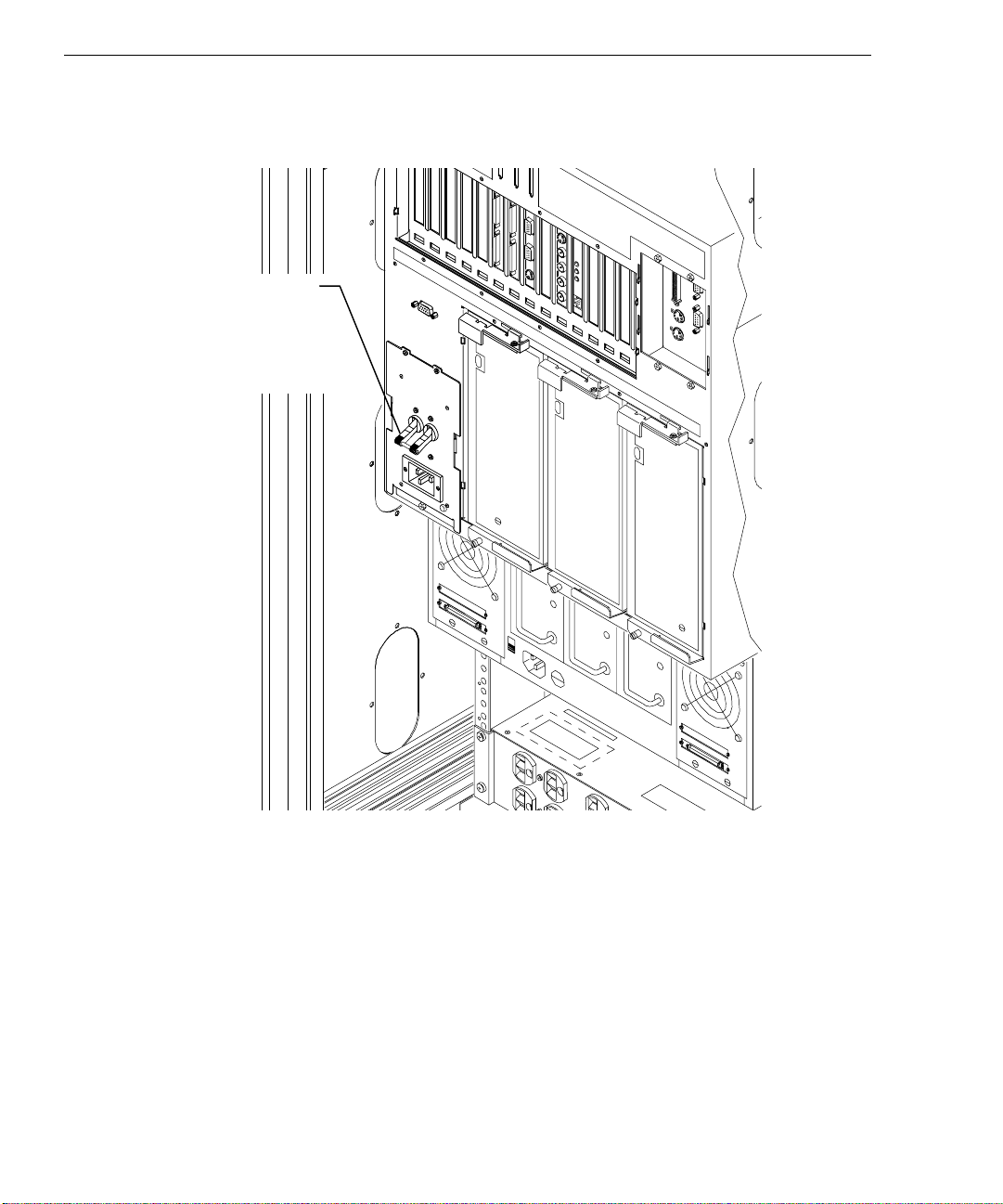
5. Ensure the base unit circuit breaker switch is in the On position (up). The switch is on the
back of the base unit, as shown in the following figure.
Circuit Breaker
Switch
(Shown in the
OFF position)
Page 17
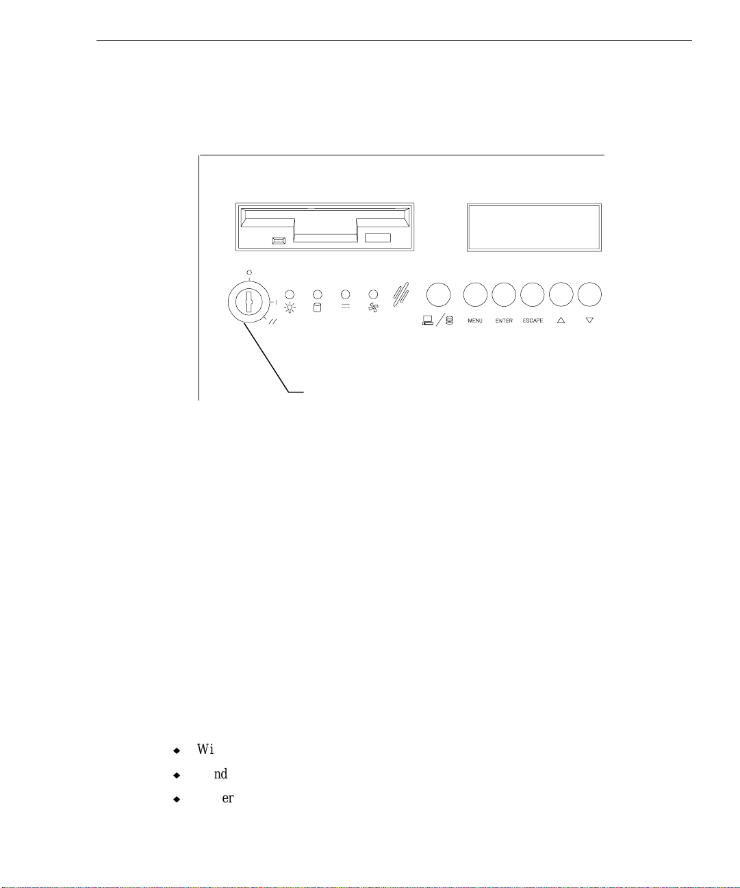
6. The system uses a three-position keyswitch on the front of the base unit for starting,
stopping, and restarting the system. Each position (o = off, | = on, // = restart) is
symbolized along the edge of the keyswitch as shown in the following figure. Start the
system by inserting the key and turning it to the on ( | ) position.
Keyswitch
The fans on the front start, the LEDs flash green and amber, the LCD screen lights and
displays startup messages, and the LEDs under the drives flash green and amber.
3
WARNING The fans on the front of the base unit are capable of drawing loose attire (clothing,
badges, necklaces, etc.) and long hair into the fans, possibly causing personal injury or
damage to the fans.
After a few moments, the LEDs remain steady green. If any of the LEDs remain amber or do
not light, there is a problem with the system. Refer to Chapter 5, “Troubleshooting,” to
determine the problem. If LEDs under the disk drives remain amber, refer to the InterRAID
documentation for troubleshooting help.
Preparing for Windows NT Setup
The first time the system is started, the system boots to a Setup screen or logon dialog for the
operating system. The system shipped with the operating system and associated system
software installed on the system’s hard disk. Intergraph installed the following system
software:
u
Windows NT operating system
u
Windows NT network software (TCP/IP and NetBEUI)
u
Driver software for the on-board SCSI adapter
Page 18

4
u
Driver software for the on-board networking adapter
u
Driver software for the installed video display adapter
u
Driver software for the installed MegaRAID controller
u
StudioZ driver and StudioZ Console software
u
The default File Allocation Table (FAT) file system
Before you go through Setup, have the following available:
u
Microsoft’s Start Here document
u
Documentation for expansion boards purchased from Intergraph
u
Several blank, formatted diskettes to create backup diskettes containing system software.
Obtain and record the following information:
u
Your name, and the name of your
company or organization:
u
The CD Key from the Windows NT
Workstation CD case, or the Product ID
Number from Start Here or the
registration card:
u
A username and password for setting up
a user account.
If the system is connected to a network, obtain and record the following information from your
network administrator:
u
Computer name for your system:
u
Workgroup name (if the system will be
part of a workgroup):
u
Domain name (if the system will be part
of a Windows NT domain):
Page 19

If the system is connected to a network that uses the Transmission Control Protocol/Internet
Protocol (TCP/IP), obtain and record the following TCP/IP networking information from your
network administrator:
u
Internet Protocol (IP) address for your
system:
u
IP subnet mask for your system:
u
IP domain name for your network:
u
IP address for your network’s default
gateway:
u
IP addresses for your network’s
Domain Name System (DNS) servers,
if any:
The Windows NT delivery media contain software and drivers for both Reduced Instruction
Set Computing (RISC)- and Intel-based systems. When installing Windows NT distribution
files, make sure to install them from the \
I386 directory (the Intel software directory) on the
delivery media. For example, if you are installing a device driver from the Windows NT
CD-ROM, key in the following when asked for the path to the file, where drive is the drive
letter for the CD-ROM drive:
5
drive:\i386
Going Through Windows NT Setup
The first time you start the system, it boots to a Setup screen. Select Next to start Setup, and
follow the instructions provided on-screen to complete the process. Take the default settings
provided by Setup, except as noted in the following text. You can set up a user account and
join a workgroup or domain after you configure the video display, the sound processor, and
networking.
u
Allow Setup to configure the network only if you have an installed network adapter, and
the system is connected to the network.
u
When prompted to create an Emergency Repair Disk, do so.
u
If you do not set up a user account during Setup, press ENTER or select OK at the logon
dialog to log on to the operating system.
For more information on Setup, and on using the interface features of the operating system,
refer to the operating system documentation and Help.
Page 20

6
Using the Welcome Dialog
After going through Setup, a Welcome dialog displays. This dialog gives you easy access to a
few first-time startup tasks you should complete before proceeding. The Welcome dialog
presents several actions you can perform. Among others, they are: creating backup diskettes
of system software, creating a Repair Disk or Startup Diskette, and viewing the StudioZ RAX
System Introduction.
Creating Backup Diskettes
Select Version Manager to run the InterSite Version Manager utility. Use this utility to create
backup diskettes containing drivers and other system software products that were installed on
the system before shipment. You may need these backup diskettes later -- for example, if you
have to re-install a device driver or the operating system.
CAUTION If you do not use Version Manager to create backup diskettes for system software, you may
not be able to re-install critical system software or the operating system if needed.
NOTE You may not have to create backup diskettes for system software. If Version Manager does
not list drivers or other system software products, they are available on the operating system
software CD-ROM or on backup diskettes delivered with expansion boards.
If the system requires Quick-Fix Engineering (QFE) update software, it is included in the
system software available for backup diskette creation. QFE update software contains fixes
for operating system problems or limitations on your Intergraph system, and is only shipped
with the system if it is needed. If QFE update software is shipped with the system, you should
create a QFE backup diskette for use if you have to re-install the operating system.
Refer to Version Manager Help for information on creating Intergraph system software and
other diskettes. Check the Intergraph Bulletin Board Service (IBBS) and vendor bulletin
boards frequently for new and updated drivers.
Creating a Repair Disk or a Startup Diskette
If you did not create an Emergency Repair Disk (Windows NT Workstation) during Setup,
select Repair Disk to create the appropriate diskette. The files on these diskettes can restore
the original contents of a damaged Registry (that is, at the time the operating system was
installed), along with the standard operating system drivers. You should also create a Repair
Disk after you finish configuring the system. The operating system documentation and Help
contain additional information about creating a Repair Disk.
Page 21

7
Reviewing the
Select System Intro to display the System Introduction. This document is an online
introduction to your new system in Windows Help 4.0 format, covering such subjects as
system features, system controls and connections, and Intergraph customer support. Review
the information in the System Introduction to become more familiar with your system.
System Introduction
What Now?
Refer to Chapter 2, “Configuring the System,” to configure the system for use.
Page 22

8
Page 23

2 Configuring the System
After setting up the system hardware and starting the system, you must configure the system
for use. Follow the instructions in this chapter to configure the system.
Configuring the Video Display Driver
When you start your system for the first time, it uses the installed RealiZm graphics
accelerator running at standard VGA resolution (640 x 480) to run the video display. For the
system to use its installed graphics accelerator at other display resolutions, you must configure
the RealiZm video display driver for use with the installed graphics accelerator. This driver is
installed on the system disk, and you created a backup diskette for it using Version Manager
(refer to Chapter 1 for information on Version Manager).
Open Display in the Windows NT Control Panel, and use the Display Properties dialog to
configure the RealiZm video display driver. Refer to the RealiZm documentation and Help
delivered with the system, and to the
drivers, for detailed configuration information. Refer to the operating system documentation
and Help for information on using the Display Properties dialog to configure the driver.
README.TXT files delivered with the video display
9
Dual-Screen Display
On a system set up for dual-screen display (using two RealiZm graphics accelerators), the
video display driver treats the combined display area of the dual screens as a single canvas
that covers both screens. In this Full Canvas style, windows centered on the canvas are split
between the two screens. This includes most system dialog boxes.
For detailed instructions on selecting a dual-screen style, refer to the RealiZm documentation
delivered with the system.
Full Drag and Cursor Configuration
If you use 3D applications with the RealiZm driver, the video display may update slowly when
you drag objects across it. To avoid this inconvenience, turn off full drag before using 3D
applications with these video drivers.
Page 24

10
To turn off full drag:
1. Open Desktop in the Windows NT Control Panel.
2. Under Applications, clear the Full Drag check box; then select OK.
Windows NT lets you use software cursors, such as decorated or animated cursors, in place of
the standard cursor. If you use a software cursor while running an OpenGL application, the
performance of that application will drop sharply whenever you position the software cursor in
that application’s window. For optimum performance of OpenGL applications, Intergraph
recommends that you use only the standard cursor.
Using RealiZm As the Default Video Display Driver
After configuring the video display and restarting the system, you should configure the system
to use the RealiZm video display driver by default.
To use the RealiZm video display driver by default:
1. Open System in the Windows NT Control Panel. The System dialog displays.
2. Under Operating System, select the appropriate non-VGA Windows NT Workstation
option from the Startup list; then select OK.
Correcting Video Display Problems
If the system’s video display is black, not synchronized, or distorted after you restart the
system, you may have a video configuration problem. Do not press
to the Windows NT operating system. Instead, try to correct the problem by using the Last
Known Good option to return the system to the last know good configuration recorded by
Windows NT.
To use the Last Known Good option:
1. Power down and restart the system.
2. Press the space bar at the following prompt:
Press space bar NOW to invoke the Last Known Good Menu
If using the Last Known Good option fails to correct the video display problems, you can
obtain a functional video resolution by restarting the system in VGA mode.
To restart the system in VGA mode:
1. Power down and restart the system.
CTRL+ALT+DEL to log on
Page 25

2. At the boot screen, select the following option:
Windows NT Workstation [VGA mode]
After logging on to Windows NT in VGA mode, check for the following common
configuration problems and solutions.
u
A multi-sync monitor is connected to the system, but a multi-sync monitor type is not
selected in Video Configuration, and the display driver cannot determine this by querying
the monitor. Select an appropriate multi-sync monitor type.
u
A selected resolution, depth, or refresh rate is not supported by the multi-sync monitor.
Try different settings in Video Configuration.
u
The Dual Screen option is selected in Video Configuration, but only one video board is
detected. Clear the Dual Screen option.
u
A multi-sync monitor is selected in Video Configuration, but a monitor with different
video timings (such as an Intergraph InterVue monitor) is connected to the system. Select
the appropriate monitor type as described previously.
u
The monitor selection in Video Configuration is inappropriate for the multi-sync monitor
attached to the system. Restart the system in VGA mode, then select a new monitor as
described previously.
11
u
A graphics resolution and color depth has been selected that exceeds installed display
memory. Restart the system in VGA mode, then open Display in the Control Panel to reinstall and configure the video display driver.
Restart the system and select Windows NT Workstation to use the reconfigured video display
driver. If problems persist, contact the Intergraph Customer Response Center for help.
Support for Heidi Graphics
The RealiZm graphics accelerators on StudioZ systems support Heidi graphics for 3D Studio
MAX. Intergraph’s Heidi Device Driver, which depends on the Intergraph Display Driver for
RealiZm graphics accelerators, provides the support.
The Heidi Device Driver is installed during installation of the Intergraph Display Driver for
RealiZm graphics. After you install 3D Studio MAX on your system, copy the Heidi Device
Driver file
3
DSMAX\DRIVER directory.
NOTE Use the version of the Heidi driver that matches the version of the display driver.
Refer to the README.TXT file delivered with the Heidi Device Driver for detailed instructions
on the driver and any associated files.
GLZIHDD.HDI from the Windows NT Workstation SYSTEM32 directory to the
Page 26
12
Configuring and Using the RAID Disk Arrays
Description of RAID Cabinets
The StudioZ RAX contains a disk cabinet internal to the base unit, plus a separate external
disk cabinet. Each cabinet has eight slots for installing RAID disk drives. The cabinet slots
are numbered from 1 to 8, starting with the right slot. Each slot also has a corresponding SCSI
ID number, which is determined by the hardware configuration of the cabinet itself and the
installed RAID controllers.
u
For more information on the internal disk cabinet, refer to the System Reference
documentation.
u
For more information on RAID controllers and external disk cabinets, refer to the
InterRAID documentation.
The standard system configuration includes eight RAID disk drives and two RAID controllers.
Four of the disk drives are installed in each disk cabinet. The disk drives contain an external
label to identify each disk drive, such as:
4 GB
IDCHNADP
The spaces above ADP, CHN, and ID are filled in before shipment to identify the drives.
u
ADP means the RAID controller (adapter) number connected to the cabinet
u
CHN means the RAID SCSI bus channel of the adapter (each adapter has three channels)
u
ID means the identification number of the drive in the slot.
NOTE When the standard disk drives are configured by Intergraph (as described below), they
assume the SCSI ID number of the slot.
Each cabinet has a dedicated RAID controller attached to it, via internal SCSI cables.
Although the controllers have three channels, the cabinets use only two of them. The
following figures show the cabinet slots, with their attached controller, and the channel and
SCSI ID designations. The standard eight disk drives are installed in slots 1, 2, 5, and 6 in
each cabinet, as shown by the shaded slots.
Page 27
Internal Disk Cabinet:
Channel 2 Channel 1
13
Adapter 0
Slot 8
SCSI
ID 4
Slot 7
SCSI
ID 2
External Disk Cabinet:
Channel 1 Channel 0
Slot 8
SCSI ID
4
Slot 7
SCSI ID
2
Slot 6
SCSI
ID 1
Slot 6
SCSI ID
1
Slot 5
SCSI
ID 0
Internal Disk Cabinet
Adapter 1
Slot 5
SCSI ID
0
Slot 4
SCSI
ID 4
Slot 4
SCSI ID
4
Slot 3
SCSI
ID 2
Slot 3
SCSI ID
2
Slot 2
SCSI
ID 1
Slot 2
SCSI ID
1
Slot 1
SCSI
ID 0
Slot 1
SCSI ID
0
External Disk Cabinet
Page 28

14
Standard RAID Disk Drives Configuration
All four drives in each cabinet are packed as one logical drive (via MegaRAID Power
Console), and the two logical drives are configured as a stripe set (via Windows NT Disk
Administrator). This makes all the disk drives in the two cabinets one partition.
u
4 GB disk drives result in a 32 GB partition.
u
9 GB disk drives result in a 72 GB partition.
When using MegaRAID BIOS or Power Console, the program identifies the drives as Ax-N.
Ax represents the logical drive (the array of disks, or the disk array) of the cabinet that the
drives are a part of, and N represents the disk drive number within the logical drive.
The following figures show the correlation between the disk drives (labeled), their slot
location (shaded areas), and how they are identified in MegaRAID BIOS and Power Console
(MegaRAID ID).
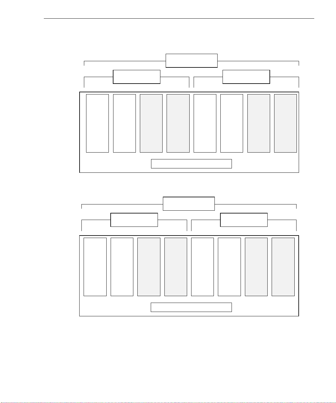
Internal cabinet:
Adapter 0
Slot 8
ID 4
Channel 2 Channel 1
Slot 7
ID 2
Slot 6
ID 1
ADP 0
CHN 2
ID 1
A0-3
Slot 5
ID 0
ADP 0
CHN 2
ID 0
A0-1
Internal Disk Cabinet
Slot 4
ID 4
Slot 3
ID 2
Slot 2
ID 1
ADP 0
CHN 1
ID 1
A0-2
Slot 1
ID 0
ADP 0
CHN 1
ID 0
A0-0
Disk Label
MegaRAID
ID
Page 29

External cabinet:
Channel 1 Channel 0
15
Adapter 1
Slot 8
ID 4
Slot 7
ID 2
Slot 6
ID 1
ADP 1
CHN 1
ID 1
A0-3
Slot 5
ID 0
ADP 1
CHN 1
ID 0
A0-1
Slot 4
ID 4
Slot 3
ID 2
Slot 2
ID 1
ADP 1
CHN 0
ID 1
A0-2
Slot 1
ID 0
ADP 1
CHN 0
ID 0
A0-0
External Disk Cabinet
For optimal performance, each logical drive is configured in MegaRAID BIOS (or Power
Console) with the following characteristics:
u
RAID level 0
u
64K stripe size
u
Write-back write policy
u
Cached I/O
u
Read-ahead read policy
Disk Label
MegaRAID
ID
Additional Disk Drives Configuration
For systems that ship with drive upgrade kits (eight drives), the new drives must be configured
the same as the eight standard drives.
u
The four additional drives in each array must be packed as one logical drive using
MegaRAID Power Console (or the MegaRAID BIOS).
u
The two new logical drives must be striped into a single stripe set, via Windows NT Disk
Administrator.
The final result is the system has four logical drives, but only two stripe sets (disks) as seen by
the operating system.
Page 30

16
NOTE The system can be further expanded with two more external cabinets with disk drives . The
same process of configuring the drives must be followed for the drives in the new cabinets.
The following steps provide the basic information to pack the drives into a logical drive, but
you should refer to the InterRAID documentation delivered with the system for more complete
information.
To pack the new drives into a logical drive (disk array):
1. Start the MegaRAID Power Console utility from the MegaRAID program group.
2. Select an adapter that has the four new unconfigured disk drives.
3. From the Adapter menu, select the Configuration submenu, then select the Custom
Configuration option. Select the drives in the following order: A1-0, A1-1, A1-2, A1-3.
4. When the configuration has been applied, the Create Logical Drive dialog displays. Set
the logical drive options to:
−
RAID level = 0
−
Stripe Size = 64K
−
Write Policy = write-back
−
I/O = cached
−
Read Policy = read-ahead
NOTE Before you select Apply, note the amount of disk space displayed. If this amount changes
when you select Apply, select Apply again to ensure the changes take effect.
4. Select Apply, and then select OK to save the configuration and initialize the drives.
5. Select the second adapter, and then repeat steps 3 through 5.
The following figures show how the new drives (shaded) are labeled and identified in
MegaRAID BIOS and Power Console.
Page 31

Internal cabinet:
Channel 2 Channel 1
17
Adapter 0
Slot 8
ID 4
ADP 0
CHN 2
ID 4
A1-3
External cabinet:
Slot 8
ID 4
Slot 7
ID 2
ADP 0
CHN 2
ID 2
A1-1
Slot 7
ID 2
Slot 6
ID 1
ADP 0
CHN 2
ID 1
A0-3
Channel 1 Channel 0
Slot 6
ID 1
Slot 5
ID 0
ADP 0
CHN 2
ID 0
A0-1
Internal Disk Cabinet
Slot 5
ID 0
Slot 4
ID 4
ADP 0
CHN 1
ID 4
A1-2
Adapter 1
Slot 4
ID 4
Slot 3
ID 2
ADP 0
CHN 1
ID 2
A1-0
Slot 3
ID 2
Slot 2
ID 1
ADP 0
CHN 1
ID 1
A0-2
Slot 2
ID 1
Slot 1
ID 0
ADP 0
CHN 1
ID 0
A0-0
Slot 1
ID 0
Disk Label
MegaRAID
ID
ADP 1
CHN 1
ID 4
A1-3
ADP 1
CHN 1
ID 2
A1-1
ADP 1
CHN 1
ID 1
A0-3
ADP 1
CHN 1
ID 0
A0-1
External Disk Cabinet
ADP 1
CHN 0
ID 4
A1-2
ADP 1
CHN 0
ID 2
A1-0
ADP 1
CHN 0
ID 1
A0-2
ADP 1
CHN 0
ID 0
A0-0
Disk Label
MegaRAID
ID
Page 32

18
When the logical drive is configured, restart the system. Then use the Windows NT Disk
Administrator to create a software stripe set for the new logical drives. A stripe set combines
the two logical drives into one disk as seen by the operating system.
To create the software stripe set:
1. Start Disk Administrator from the Administrative Tools program group.
2. Select the drives to stripe by pressing
3. Select Create Stripe Set from the Partition menu, and specify the size of the stripe set.
4. Select Commit Changes Now from the Partition menu.
5. Select Format from the Tools menu to format the stripe set, and select the NTFS file
system type.
6. When formatting is complete, select OK.
7. Select Exit from the Partition menu to exit the Disk Administrator utility.
For more information, refer to Disk Administrator Help and the online Windows NT
documentation.
Configuring Networking
If the system has an installed network adapter, you must configure the operating system to use
it. Before you configure networking, make sure that the system has an installed network
adapter, and that the system is connected to the network.
To configure networking, open Network in the Control Panel. Follow the instructions in the
dialogs to set up the system to use a network. Be sure to set up the appropriate network
protocols, such as TCP/IP and NetBEUI, for the network to which your system is connected.
Refer to the documentation for the installed network adapter for detailed configuration
instructions. Refer to the operating system documentation and Help for information on setting
up the system to use a network.
CTRL and clicking on the free space.
Updating the Operating System
Microsoft Service Packs contain the latest improvements and system fixes for Microsoft
operating systems. Service Packs are created by Microsoft for post-release support. You can
obtain Service Packs from Microsoft’s World Wide Web and FTP sites free of charge.
CAUTION If Intergraph provides a Service Pack through the IBBS or with a product or system, it has
been certified against Intergraph hardware as described in the announcement of its
Page 33

availability. If you obtain a Service Pack from any other source, be aware that it may not be
certified against your Intergraph hardware.
19
Page 34

20
Page 35

3 Using the System
Now that your system is up and running, and all the software is configured, review this chapter
to become familiar with system precautions, starting and stopping the system, and user
features, such as:
u
Intruder alert and hardware fault detection system
u
Liquid crystal display (LCD) screen
u
System status and RAID status menus
u
Status LEDs
u
Rack-mounted hardware
Taking Precautions
The front and side stabilizer feet of the Intergraph rack must be extended at all times. Do not
push on or lean against the rack.
21
When multiple slide rail devices are installed in the Intergraph rack, only one device may be
extended at a time. Always push the extended device back into the rack before extending
another one.
WARNING Extending more than one device at a time could cause the rack to fall forward, causing
damage to the equipment and severely injuring anyone standing in front of the rack.
Starting and Stopping the System
While the system is running, you can restart the system or shut it down and power it off
completely.
u
To restart the system, turn the key to the // position for a moment, and then back to the |
position.
u
To stop the system, perform an orderly system shutdown, and then turn the key to the O
position. An orderly shutdown consists of stopping applications, logging off Windows
NT Server, and pressing
dialog.
CTRL+ALT+DELETE. Select Shutdown from the NT Security
Page 36

22
The following figure shows the keyswitch on the front of the system.
43215
Keyswitch
Always power on or power off the system in the following sequences:
u
Power on any external InterRAID-8 cabinets connected to the system base unit and wait
for the audible beep before powering on the system base unit.
u
Power off the system base unit before powering off any external InterRAID-8 cabinets. If
you power off the external InterRAID-8 cabinets first, the RAID controller will read the
drives in those cabinets as dead the next time you power on the system. If this happens,
refer to the InterRAID documentation delivered with the system.
Hardware Fault Alert
System hardware faults (errors such as fan failure or memory failure) can be detected, and the
system can notify you of the error via the audible alarm and the LCD screen. When the error
alert is enabled, the system sounds an alarm and writes a message to Microsoft NT Event Log.
You can use the LCD screen menus to view the component that is generating an alert
condition. Using the LCD screen and the status menus are described in the following sections.
Page 37

LCD Screen
The LCD screen displays system and component information through a set of menus that
apply to the base unit and to the internal RAID section. The LCD screen is powered on
whenever the system is plugged in, so that status information is available even if the system is
powered off or not running an operating system. The six buttons below the LCD screen let
you navigate the menus that control the system’s firmware operation.
23
LCD Screen
43215
LCD Buttons
The six LCD screen buttons are:
Switches between the System Status menus and the RAID Status menus,
and returns you to the previously used menu.
MENU Displays the menu options for the system status or RAID status.
ENTER Activates the selected menu item.
ESCAPE Exits the current menu.
∆
∇
Moves the cursor up the current menu choices.
Moves the cursor down the current menu choices.
You can use the LCD screen and buttons when the system is powered off, but the commands
used to display hardware status report a Sys. Off message. When the system is powered
off, the LCD screen is not lighted, but the displayed messages are visible. The LCD screen
lights bright green when the system is powered on.
Page 38

24
Startup Messages
When you turn the circuit breaker switch to the On position, the following messages display
on the LCD screen:
InterServe 650/660
Initializing . . .
InterServe 650/660
System Status Okay
NTOS_NODE_NAME
Day Date Time
The above message is the top level screen, which displays until you use the LCD screen
buttons to view the system status menus or RAID status menus. Note the following about the
top level screen:
u
The second line may display System Status Warning or System Status
FAILURE. The Warning message is accompanied by an audible beep every eight
seconds. The FAILURE message is accompanied by a continuous audible beep. These
messages indicate that conditions are favorable for a hardware error (Warning) or that an
error has occurred (Failure). In these cases, press the
STATUS menus to determine the hardware at fault.
MENU button and use the SYSTEM
NOTE The second line may display System Monitor, without any status message. If so, then this
indicates the system polling function has been disabled. Refer to “Change the System Status
Polling Interval” for more information.
u
The third line displays the system’s node name if the software product HWMON_IS650
is installed. Otherwise, the line is blank.
u
The items on the fourth line can be configured using the Set RealTimeClock options
in the UTILITY menu. This line is updated at the interval set on the System Status
Poll option under the UTILITY menu. The default interval is 9.9 seconds.
Press the
MENU button to see the system status menus, or the SYSTEM/RAID button to switch to
the RAID status menus. The information displayed in the system status menus and the RAID
status menus are listed in the following tables.
Page 39

System Status Information
The following table provides a view of how to use the configurable options and view status
information for the system. - verify page numbers and section headings
25
What do you want to do?
Configure the audible
alarm operation
View the internal
temperatures
View the fan status
View the power supply
status
View the voltage status
View processor board
information
View processor (CPU)
information
View general memory
information
View memory SIMM
socket information
View I/O expansion board
information
View PCI expansion slot
information
View ISA expansion slot
information
View power distribution
board and system monitor
firmware information
View I/O connector board
information
View LCD board
information
Set the system time and
date
Set the system monitor
configuration protection
password
Follow this menu path See page
Alert/Alarm > Audible Alarm > Sound
Alarm Upon
System Status > Temperature
System Status > Fans
System Status > Power Supply
System Status > Voltages
System Config. > Processor Board
System Config. > Processor Board >
Processors
System Config. > Processor Board >
Memory
System Config. > Processor Board >
Memory > SIMM Rows X and Y
System Config. > I/O Expansion Bd.
System Config. > I/O Expansion Bd.
> PCI Expansion Cards
System Config. > I/O Expansion Bd.
> ISA Expansion Cards
System Config. > Power Plane
System Config. > I/O Connector Bd.
System Config. > LCD Display Panel
Utility > Set RealTimeClock
Utility > Set Password
28
28
29
30
31
31
32
32
33
33
33
34
34
34
34
35
36
Page 40

26
What do you want to do? Follow this menu path See page
Change the polling interval
Change the ambient air
temperature warning heat
threshold
View state of system
monitor firmware when last
rebooted
Manually reboot the system
monitor firmware
RAID Status Information
The following table provides a view of how to use the configurable options and view status
information for the internal RAID section.
Utility > System Status Poll
Utility > Heat Threshold
Utility > Last Reboot
Utility > Firmware Reboot
37
37
37
38
What do you want to do?
Turn off the RAID alarm
View the firmware
information
View the last power-on self
test (POST) results
View the internal
temperature
View SCSI ID information
View or change the internal
heat threshold
Follow this menu path See page
TURN OFF ALARM
HARDWARE MENU > FW REVISION
HARDWARE MENU > POST RESULTS
HARDWARE MENU > INTERNAL TEMP
OPTIONS MENU > SCSI ID MENU
OPTIONS MENU > HEAT THRESHOLD
39
39
39
39
40
40
Page 41

Using the System Status Menus
The following system status menus let you define how the intruder alert and audible alarm
operates, view hardware configuration details for the system, and define other firmware
operations. When the LCD displays the top level message (InterServe 650/660), press
the
MENU button to go to the system status menus, as follows:
Alert/Alarm
System Status: status
System Config.
Utility
u
Alert/Alarm lets you enable and temporarily defeat the intruder alert alarm (if it is
enabled). The alert is disabled by default, and should not be enabled in StudioZ RAX
systems. You can also configure the alarm to sound upon detection of a system problem
(power supplies, fans, memory, and so on).
u
System Status lets you view the status of internal system components, including
temperature, fans, and power supplies. If a problem is detected, then the System
Status line displays : WARN, or FAIL to show that one or more components need
attention. Otherwise, it displays Okay.
27
u
System Config. lets you view information about the system boards, including board
revision and applied ECO level.
u
Utility lets you set the system time and date, establish a firmware protection
password, view the system state when it was last rebooted, and reboot the firmware.
A cursor appears to the left of the menu options. Press the arrow buttons to move the cursor
to an option, then press the ENTER button to select it.
Configure the Audible Alarm Operation
Path: Alert/Alarm > Audible Alarm > Sound Alarm Upon
1. When the cursor is by Alert/Alarm press
2. Move the cursor to Audible Alarm and press
Sound Alarm Upon
Status Error: Yes
Intruder: Yes
3. Move the cursor to Status Error and press ENTER to switch between Yes and No.
When set to Yes, any detected error causes an audible alarm to sound.
4. Move the cursor to Intruder and press
ENTER.
ENTER. The screen displays
ENTER. The screen displays
Page 42

28
Intruder Alarm Sound
Enable/Disable
Password:
5. If a password is set, you must key in the current password to change the state. If you do
not key in the correct password within 16 seconds, the previous menu screen displays.
6. When set to Yes, the alarm sounds 15 seconds after either rack door is opened (unless the
alarm is defeated or the alert is disabled as described previously).
View the Internal Temperatures
Path: SYSTEM STATUS > Temperature
TEMPERATURE: status displays a general indication of system temperature. When all sensors
detect normal temperatures, this line displays Okay. If Wm or HOT displays, one or more of
the internal sensors is reporting a problem. Press
display the sensors:
Ambient: value status (Okay, Wm, or HOT)
Sensor1: value status (Okay, Wm, or HOT)
Sensor2: value status (Okay, Wm, or HOT)
Sensor3: value status (Okay, Wm, or HOT)
ENTER at the TEMPERATURE option to
The temperature displays for the each of the system’s four sensors. Normal temperatures are
indicated by Okay. The following table states the warm and hot (unsafe) temperatures for the
sensors.
Sensor
Ambient intake air temperature in center fan
Sensor1 between the processors and the power
Location Warm (Wm) Hot (Hot)
30 °C (86 °F) 35 °C (95 °F)
40 C (104 °F) 45 C (113 °F)
distribution board
Sensor2 next to ISA expansion slot 4
Sensor3 at the middle of I/O expansion board
CAUTION Temperatures that are approaching the unsafe levels are indicated by Wm. Any sensor that
reports a
fans are working. If room temperature is less than 80 degrees Fahrenheit (26 degrees
Celsius) and the fans are spinning, the fan speed may be too slow. Call the Customer
Response Center.
WARNING If a sensor reports
damage internal components. If the cause of the hot temperature condition is not related to
the room environment, call the Intergraph Customer Response Center.
Wm status should be monitored closely. Adjust room temperature and ensure the
HOT, power off the system to protect it from overheating, which could
40 C (104 °F) 45 °C (113 °F)
40 C (104 °F) 45 °C (113 °F)
Page 43

NOTE The threshold for the Ambient sensor can be changed. Refer to “Change the Ambient Heat
Threshold” later in this chapter. The thresholds for the internal sensors cannot be changed.
The Scale option lets you change the displayed temperature unit from degrees Fahrenheit to
degrees Celsius. Press ENTER to switch between the two scales. Press
ESCAPE to return to
the previous menu.
View the Fan Status
Path: SYSTEM STATUS > Fans
Fans: status displays a general status of the three front cooling fans and the two fans inside
each power supply. When all fans are operating properly, Okay displays. If XX FAILURES
is listed, then one or more of the front cooling fans or power supply fans is generating a
problem.
ENTER when the cursor is by FANS to see the status for each fan. The following screen
Press
displays:
LEFT: status (Off, Ok, BAD)
CENTER: status (Off, Ok, BAD)
RIGHT: status (Off, Ok, BAD)
29
Pws1#1: status (Off, Ok, BAD)
Pws1#2: status (Off, Ok, BAD)
Pws2#1: status (Off, Ok, BAD)
Pws2#2: status (Off, Ok, BAD)
Pws3#1: status (Off, Ok, BAD)
Pws3#2: status (Off, Ok, BAD)
When the status is Ok, the fan speed is adequate to provide cooling. If the speed decreases
below what is required for cooling, BAD displays. When the system is not powered on, the
fan status displays Off. Press
View the Power Supply Status
Path: SYSTEM STATUS > Power Supply
Power Supply: status displays Okay, WARN, or FAIL. If WARN displays, a fan inside one or
more power supplies has failed, but the power supply is still working. This poses a condition
that could lead to overheating, causing the entire power supply to fail If FAIL displays, one
of the power supplies has completely failed. Call the Customer Response Center if the WARN
or FAIL message displays.
ESCAPE to return to the previous menu.
Page 44

30
To view specific power supply status, move the cursor to Power Supply and press ENTER.
The following lines display:
Supply #1: status <Absent, Okay, or FAIL> will FAIL display if a pws comp fails?
Supply #2: status <Absent, Okay, or FAIL>
Supply #3: status <Absent, Okay, or FAIL>
General status <NonRedundantSupply or PowerSupplyFailure
>
To view specific power supply information, press
#X: FAIL line. The following information displays:
AC: (Absent, Okay, or FAIL)
DC: (Off, Absent, Okay, or FAIL)
Fan #1: (Off, None, Okay, or FAIL)
Fan #2: (Off, None, Okay, or FAIL)
If the General Status line shows NonRedundantSupply, then the system is missing one or
two power supplies. The second and third supply should be installed immediately. If the line
shows PowerSupplyFailure, then call the Customer Response Center.
View the Voltage Status
Path: SYSTEM STATUS > Voltages
Voltages: status displays either Okay or FAIL. If FAIL displays, then check the
individual voltage rails to identify the problem. Press
Voltages. The following lines display:
+3.3V: status (System Off, X.XXV Okay, or X.XXV FAIL)
+5Unsw X.XXV status (Okay, or Fail)
+5.0V: status (System Off, X.XXV Okay, or X.XXV FAIL)
-5.0V: status (System Off, X.XXV Okay, or X.XXV FAIL)
+ 12V: status (System Off, X.XXV Okay, or X.XXV FAIL)
- 12V: status (System Off, X.XXV Okay, or X.XXV FAIL)
GTL 0: status (System Off, X.XXV Okay, or X.XXV FAIL)
GTL 1: status (System Off, X.XXV Okay, or X.XXV FAIL)
CPU 0: status (System Off, Absent, X.XXV Okay, or X.XXV FAIL)
Nominal CPU 0: x.xV
CPU 1: status (System Off, Absent, X.XXV Okay, or X.XXV FAIL)
Nominal CPU 1: x.xV
CPU 2: status (System Off, Absent, X.XXV Okay, or X.XXV FAIL)
Nominal CPU 2: x.xV
CPU 3: status (System Off, Absent, X.XXV Okay, or X.XXV FAIL)
Nominal CPU 3: x.xV
ENTER when the cursor is by the Supply
ENTER when the cursor is on
Page 45

Occasionally a voltage rail for a power supply will fail intermittently, which shows up in the
above set of status lines. If the FAIL message appears, and then goes away, there is no cause
for alarm. However, if the FAIL message continues to display, or reoccurs frequently, a
problem exists in the system. Call the Customer Response Center.
View Processor Board Information
Path: SYSTEM CONFIG > Processor Board
The installed processor board number (MSMTxxxxx) and its engineering change level
(ECO xx) display. Press
ESCAPE to return to the previous menu.
View Processor (CPU) Information
Path: SYSTEM CONFIG > Processor Board > Processors
The following information about the processors (CPUs) display:
CPU 0: status (System Off, Present, Absent)
CPU 1: status (System Off, Present, Absent)
CPU 2: status (System Off, Present, Absent)
CPU 3: status (System Off, Present, Absent)
31
Present shows the processor is properly installed in the socket. Absent shows the socket
is empty.
View General Memory Information
Path: SYSTEM CONFIG > Processor Board > Memory
Memory: status displays the current installed memory (XXXX MB) or shows that an invalid
memory configuration exists (Invalid). Below the Memory status line, an additional
memory status message displays. The message is one of the following:
Message
SIMM Pair Mismatch
SIMM MismatchInRow
Varying Interleave
No SIMM in Row 0&1
50 ns SIMM Warning
Meaning
A pair of SIMMs in a row are different sizes (densities).
Two or more SIMM sizes are installed in a row.
Two rows have difference interleaves, all rows must have the
same interleave.
At least one pair of SIMMs must be installed in Row 0&1.
Installed SIMMs are 50 ns, which have not been approved for
Page 46

32
70 ns SIMM Invalid
80 ns SIMM Invalid
4 to 1 Interleaved
2 to 1 Interleaved
1 to 1 Interleaved
View SIMM Socket Information
Path: SYSTEM CONFIG > Processor Board > Memory > SIMM Rows X & X
Information about each SIMM socket, such as row, interleave and what size memory module
is installed, can be displayed. SIMM sockets are grouped according to rows of the memory
subsystem. Press
SIMM Rows 0 and 1
SIMM Rows 2 and 3
SIMM Rows 4 and 5
SIMM Rows 6 and 7
ENTER when the cursor is on Memory: status. The following lines display:
this system, and should be removed.
Installed SIMMs are 70 ns, and should be removed.
Installed SIMMs are 80 ns, and should be removed.
OK status, valid interleave.
OK status, valid interleave.
OK status, valid interleave.
To display information about the sockets included in each row, move the cursor to a row and
press
ENTER. The status of each socket in the row displays, such as:
J33 I3: status (Vacant or XXMB, XXns)
The JXX number identifies the socket number that is printed on the processor board. The IX
number indicates the interleave value of that socket in the row. If a memory module is
installed, its size and speed display. The System Reference contains a detailed discussion of
the memory subsystem, rows, and interleaves.
When the system power is off, socket information cannot be displayed. System Off
appears for each socket in this case.
View I/O expansion board information
Path: SYSTEM CONFIG > I/O Expansion Bd.
When you move the cursor to I/O Expansion Board and press enter, the board part number
(MSMTXXXX) and its engineering change level (ECO XX) display. Additionally, you can view
expansion slot information.
Page 47

View PCI Expansion Slot Information
Path: SYSTEM CONFIG > I/O Expansion Bd. > PCI Expansion Cards
ENTER when the cursor is on PCI Expansion Cards. The status for each of the
Press
twelve PCI slots displays, such as PCIslot 5: status. The status is Empty or Occupied.
Press the down arrow key to scroll through the slots. When the system is powered off, the
status displays Sys. Off. Press
ESCAPE to return to the previous menu.
View ISA Expansion Slot Information
Path: SYSTEM CONFIG > I/O Expansion Bd. > ISA Expansion Cards
ENTER when the cursor is on ISA Expansion Cards. The status for each of the four
Press
ISA slots displays, such as ISAslot 2: status. The status is Empty or Occupied. Press
the down arrow key to scroll through the slots. When the system is powered off, the status
displays Sys. Off. Press
ESCAPE to return to the previous menu.
33
Page 48

34
View Power Distribution Board Information
Path: SYSTEM CONFIG > Power Plane
Information about the power distribution board (also known as power plane) includes the
board part number (MSMTXXXX), its engineering change level (ECO XX), and the firmware
X.XX
version (FIRMWARE:
distribution board presents the menus and options for the system monitor on the LCD screen.
The RAID subsystem firmware and the system monitor firmware alternately share the LCD
screen. Press
ESCAPE to return to the previous menu.
) that is installed on the board. The firmware on the power
View I/O Connector Board Information
Path: SYSTEM CONFIG > I/O Connector Bd.
Information about the I/O connector board (which contains the connectors for external ports,
such as keyboard, mouse, and SCSI) includes the board part number (MSMTXXXX), its
engineering change level (ECO XX). Press
ESCAPE to return to the previous menu.
View LCD Board Information
Path: SYSTEM CONFIG > LCD Display Panel
Information about the LCD board (containing the LCD screen that displays the firmware
menus) includes the board part number (MSMTXXXX) and its engineering change level (ECO
XX). Press
ESCAPE to return to the previous menu.
Set the System Clock (RTC)
Path: UTILITY > Set RealTimeClock
The Set Clock (RTC) option lets you set the system’s time (seconds, minutes, and hours)
and date (day, date, month, and year). The time and date information are recorded in the
system’s real time clock and displayed on the top level LCD screen. Conversely, when you set
the system time and date through the operating system, those settings are displayed in the LCD
screen after the next operating system reboot.
The time and date elements are set two ways. Some elements allow you to increment by one
or by 10, such as seconds. Others only increment by one.
To set the system clock:
1. Move the cursor to Utility and press enter.
Page 49

2. Press enter on Set RealTimeClock. The following screen displays.
Seconds
Minutes
Hours: XX
Day: XXX
Date
Month: XXX
Year
3. To change the Hours, Day, and Month elements, move the cursor to an item and press
ENTER. The value increments by one.
4. To change the Seconds, Minutes, Date, and Year elements, move the cursor to an
item and press ENTER. These can increment by ten, so the following screen displays.
Increment
Increment by 10
Item: XX
35
5. Press
6. Press
ENTER when the cursor is on Increment to change the value by one, or move the
cursor to Increment by 10 and press
ESCAPE to accept the new time and date.
ENTER to change the value by 10.
Set the Firmware Protection Password
Path: UTILITY > Set Password
Set Password lets you protect the settings for the intruder alert and the firmware reboot.
When changing a password, you must key in the current password.
To set a firmware protection password:
1. Move the cursor to Set Password and press
(the password is a null value), then NEW: displays.
2. Key in a password, up to eight characters long, using the buttons labeled 1 through 5.
3. Press the
SYSTEM/RAID button to enter the password.
4. When Repeat: displays, key in the password again. The Password Updated
message displays, then returns to the previous screen.
NOTE If you do not enter a password within 16 seconds, or if you enter the wrong password, the SET
PASSWORD FAILED
message displays and returns to the previous screen.
ENTER. If a password has not been set
Page 50

36
Change the Polling Interval
Path: UTILITY > System Status Poll
System Status Poll lets you change the interval (in seconds) by which the firmware
reads status information from the various internal components. The polling function is
enabled by default. You can also disable the firmware from polling the system.
NOTE When disabled, the second line of the top level message (which normally displays System
Status Okay
screen, nor does the warning or failure alarm sound if an error occurs. However, if an error
occurs while the polling is disabled, the error displays in the status menus for the failing
component.
To disable or change the status polling interval:
) displays System Monitor. General status messages do not display on the
1. Move the cursor to System Status Poll and press
displays:
Sts. Poll: state (Enabled or Disabled)
Decrease Interval
Increase Interval
Interval: XX.X sec.
2. Press
ENTER on Sts. Poll and the state switches from Enabled to Disabled.
3. To change the interval, move the cursor to Decrease Interval or Increase
Interval and press
ENTER. The value shown on the Interval: XX.X sec. line
changes accordingly.
4. Press ESCAPE to set the new interval.
Change the Ambient Heat Threshold
Path: UTILITY > Heat Threshold
This option lets you change the threshold at which the ambient temperature sensor reports a
warm temperature. This option applies to the external temperature only. The heat thresholds
for the internal sensors cannot be changed.
ENTER. The following screen
Page 51

Heat Threshold lets you change the temperature at which the Ambient sensor reports a
warm condition (see “View the Internal Temperature” previously). The Ambient sensor
measures intake air temperature at the middle fan. The temperature scale is in degrees
Fahrenheit or Celsius according to the current Scale setting under Internal
Temperature.
To change the heat threshold:
37
1. Move the cursor to Heat Threshold and press
ENTER. The following lines display:
Decrease Threshold
Increase Threshold
Ambient Trsh: value
2. Move the cursor to Decrease Threshold or Increase Threshold and press
ENTER. The value shown on Ambient Trsh changes accordingly.
3. Press
NOTE The maximum threshold setting is 95 degrees Fahrenheit (35 degrees Celsius).
ESCAPE to set the new ambient threshold.
View the State of System Monitor Firmware when Last Rebooted
Path: UTILITY > Last Reboot
Last Reboot: status shows the condition of the system monitor firmware when it was last
booted. If Warm displays, the system monitor firmware has been rebooted. The system
monitor microcontroller has a hardware watchdog reset feature whereby the microcontroller
automatically reboots itself upon various error conditions. A Warm status is not cause for
immediate concern, since the system monitor firmware can be manually rebooted.
If Cold displays, then the system monitor firmware has not been rebooted since AC line
power was last applied to the system. A Cold status indicates that the system monitor
microcontroller has not malfunctioned since AC line power was last applied to the system.
Manually Reboot the System Monitor Firmware
Path: UTILITY > Firmware Reboot
Reboot Firmware lets you reboot (or restart) the firmware if necessary.
Move the cursor to Firmware Reboot and press
prompted. If you do not key in the password, the firmware does not reboot.
ENTER. Key in the password when
Page 52

38
Using the RAID Section Menus
The RAID section menu lets you turn off the audible alarm, check the status of internal RAID
hardware, and change RAID parameters. The status information and configurable items apply
only to the internal RAID section. When you switch from the system status to the RAID
status, STATUS: OK or STATUS: FAIL displays. If a failure occurs, the hardware at fault
also displays. Press the
TURN OFF ALARM
HARDWARE MENU
OPTIONS MENU
MENU button to display the RAID section menu options:
When the above menu options display, you can press the
RAID status. From the RAID status, press the
SYSTEM/RAID button to switch to the system
status. To use the menu options, move the cursor to an option and press the
u
TURN OFF ALARM option silences the audible alarm when it is sounding. This option
MENU button again to return to the
ENTER button.
only affects the alarm for the internal RAID array (disk drives, firmware, and so on).
u
HARDWARE MENU lets you check the firmware version, power on self-test (POST)
results, and the temperature of the RAID array.
u
Options Menu contains settings for RAID drive SCSI IDs, SCSI bus termination, and
heat threshold. SCSI ID displays the ID that is set for each disk drive slot in the internal
RAID subsystem. Termination displays the current termination for the SCSI busses.
Heat Threshold lets you change the temperature at which the internal RAID will
report an error. If the temperature rises above the setting, an alarm sounds and a message
displays on the LCD screen.
NOTE Intergraph recommends that you do not change the default settings for the above options.
Turn Off the RAID Alarm
To silence the alarm while it is sounding, move the cursor to TURN OFF ALARM and press
ENTER.
Page 53

View the Firmware Information
Path: HARDWARE MENU > FW REVISION
FW REVISION displays information about the current firmware installed on the RAID
backplane, to which the RAID drives and RAID cables connect. The information includes
product name (PROD: string), RAM version, ROM version, and subsystem ID (in
hexadecimal format).
View the Last POST Results
Path: HARDWARE MENU > POST RESULTS
POST RESULTS displays the status of the ROM checksum, RAM checksum, RAM
Read/Write (R/W), SCSI bus 0, SCSI Bus 1, and processor of the last time the RAID
subsystem was powered on. The status of each item is either OK or FAIL. If a POST failure
occurs, the LEDs blink and the alarm sounds. For details about POST failures, refer to the
InterRAID documentation.
39
View the Internal Temperature
Path: HARDWARE MENU > INTERNAL TEMP
INTERNAL TEMP displays the current temperature of the internal RAID subsystem. If the
temperature rises to an unsafe level, then the system beeps a warning beep every eight
seconds. Also, the InterRAID-8 status displays FAIL.
To change the temperature threshold of the monitoring system, use the HEAT THRESHOLD
option under OPTIONS MENU.
View the SCSI ID Information
Path: OPTIONS MENU > SCSI ID MENU
The SCSI ID MENU contains information about the IDs of the various components within the
disk array. These settings should not be changed. You can view information about the
following items under the SCSI ID MENU:
u
IDS ON BUS 0
u
RAID MODULE ID
u
Satellite Mode
Page 54

40
If you accidentally change an ID setting, use the RESET DEFAULT IDS command to return
the IDs to their default state.
View or Change the Internal Heat Threshold
Path: OPTIONS MENU > HEAT THRESHOLD
HEAT THRESHOLD displays the current threshold value and instructions to change it as
follows:
ARROWS TO CHANGE
ENTER TO SET
ESC TO EXIT
HEAT THRESHOLD: XXX °F
The temperature scale is always Fahrenheit. The Scale option under System Status >
Temperature does not affect this menu.
Status LEDs
The LEDs on the front of the system provide a way of determining system status at a glance if any of the LEDs are amber, there is a problem in part of the system hardware. The
following figure shows the system LEDs.
43215
LEDs
Page 55

The four status LEDs are:
System power - green when power is on, off otherwise
Disk drive status - green if all disks OK, amber if otherwise
Power Supply Status - green if all supplies OK, amber if otherwise
Fan Status - green if all fans OK, amber if otherwise
When the LEDs indicate a failure condition (amber), use the LCD screen to see more
information about the problem. If both “Power Supply Status” and “Fan Status” LEDs are
amber, a power supply is absent. The power supply should be replaced immediately.
Additionally, an alarm sounds a continuous beep if a problem occurs in the system or internal
RAID. You can turn off the beep using the Alert/Alarm command (for system hardware
errors) or the Turn Off Alarm command (for RAID errors). Refer to the sections
“Configure Audible Alarm Operation” or “Turn Off the RAID Alarm” respectively,
previously in this chapter.
Sliding Rack-Mount Devices
41
The StudioZ RAX base unit and InterRAID-8 cabinets slide out of the rack for easy access.
The base unit is designed to lock in place when fully extended.
CAUTION The InterRAID-8 cabinet does not lock in place, so use caution when extending it.
The base unit rail guides use a release button that locks into the rails. Press in the button to
allow the base unit to retract. The following figure shows the release buttons on the base unit
rail guides.
Page 56

42
Rail Guide
Release Button
(both sides)
Using the System Hardware
User information for the following hardware is provided in separate documents, delivered with
the system.
u
StudioZ and RealiZm Z10T graphics
u
Internal RAID section and InterRAID-8 cabinet disk arrays
u
100 Base-T Ethernet networking hardware
u
PC Extender
Additional technical information about the system is included in the InterServe 650, 660,
StudioZ RAX System Reference. This document is delivered with the system on the boot drive.
Refer to the Preface for information about obtaining the System Reference.
Page 57

4 Configuring the BIOS
The Basic Input Output System (BIOS) stores various system operating parameters, such as
the boot sequence and the type of video display, in non-volatile memory referred to as CMOS
RAM. When you power off the system, a lithium battery on the I/O Expansion board provides
power to CMOS RAM, which retains the system parameters. Each time the system is powered
on, the BIOS uses the stored system parameters to configure the system.
The BIOS can be configured by manually changing system parameters, or by installing a new
BIOS.
u
The AMIBIOS Setup program allows you to manually change the system operating
parameters. This chapter provides the details of using the AMIBIOS Setup program,
which is stored, along with the BIOS, in the flash EPROM on the I/O Expansion board.
u
When necessary, you can install a new BIOS to the flash EPROM using the Flash
Programming Utility (FPU). Refer to “Reprogramming the BIOS” for instructions.
43
Using AMIBIOS Setup
The AMIBIOS Setup menus and options discussed in this section apply to BIOS 764xx.ROM,
where xx is the version. The BIOS version number is displayed on the American Megatrends,
Inc., banner message similar to the following:
AMIBIOS (C) 1994 American Megatrends Inc.,
(C) 1996 Intergraph Corporation (764XX)
To start AMIBIOS Setup:
1. Restart the system. The American Megatrends banner screen displays with the following
message:
Press DEL to enter Setup
2. Press
These menus allow access to parameters for configuring the BIOS to suit your own needs or
perform maintenance as needed. The following sections describe in detail the parameters you
can access through each menu. While using AMIBIOS Setup, remember these tips:
DELETE. AMIBIOS Setup displays with the following menus: Setup, Security,
Utility, and Default.
Page 58

44
u
To access Help, press ALT+H. The Keystroke/Mouse Convention list displays, which
explains how to select Setup menu items with the mouse pointer and with keys. Press any
key to close the list and return to AMIBIOS Setup.
u
To change a parameter’s value, move the pointer to a parameter and click the mouse
button. An Options menu displays allowing you to select one of the choices.
u
When you are at the main menu in AMIBIOS Setup, press ESC to exit. If the Save
Changes and Exit option is highlighted, press
while in the program will be saved. If you select the Continue option, then you will return
to AMIBIOS Setup.
u
You can set a password to prevent unauthorized users from accessing AMIBIOS Setup.
Refer to the section, “Security Menu,” later in this chapter for instructions.
Setup Menu
Five icons display in the Setup menu: Standard, Advanced, Chipset, PCI/PnP, and Peripheral.
Standard
ENTER to exit and any changes you made
Pri Master, Pri Slave, Sec Master, Sec Slave
These parameters provide support for Integrated Device Electronic (IDE) controller cards.
Each of the parameters contain the following options: Type, LBA/Large Mode, Block Mode,
32bit Mode, PIO Mode. If you install IDE cards into the system, refer to the card’s
documentation for the values to which these options should be set.
Date/Time
Select the Date/Time icon to display the current system date and time values. The time
displays in the 24-hour clock format.
To change the system date and time:
1. Click on the incorrect value with the mouse pointer or press the
TAB key until the value
highlights.
2. Click on the + or - buttons to change the value, or enter the correct value from the
keyboard.
3. Press
ESC to save the new values and return to Standard Setup.
Page 59

Floppy A, Floppy B
The Floppy A and Floppy B icons allow you to specify the type of floppy disk drive installed
in the system.
NOTE The floppy disk drive A parameter is preset to 1.44 MB 3.5-inch. Do not change the
parameter unless you replace floppy drive A with a different capacity disk drive.
NOTE The floppy disk drive B parameter is preset to Not Installed, unless an optional drive has been
installed prior to shipment. Do not change the parameter unless you install an optional floppy
disk drive.
To change the floppy drive parameters:
1. Select the Floppy A or Floppy B icon.
2. Press the up and down arrow keys or click in a box to select the correct parameter for the
floppy disk drive.
45
3. Press
Advanced
System Boot Up Sequence
This parameter specifies the device sequence for system boot up. The default is C:, A:,
CDROM, which means the system attempts to boot from drive C first. If unsuccessful, it will
attempt to boot drive A, then the CD-ROM drive. By default, C: is the system disk drive, and
A: is the floppy disk drive. Change this parameter to A:, C:, CDROM to boot the system from
the floppy disk drive, or change it to CDROM, A:, C: to boot from the
CD-ROM drive. Refer also to Operating System Boot Device parameter in “Chipset.”
System Boot Up Num Lock
This parameter, when set to On (default), disables the arrow keys on the numeric keypad. The
Num Lock option on the keyboard can be turned off and on while the system is operating.
Floppy Drive Seek at Boot
When set to Enabled, AMIBIOS performs a Seek command on floppy disk drive A before
booting the system. The default setting is Disabled.
ENTER to accept the change, or click on the close icon in the upper left corner of the
floppy disk drive configuration menu.
Page 60

46
Mouse Support
This parameter enables or disables mouse support in AMIBIOS Setup. The values are
Enabled (default) and Disabled. If disabled, the mouse will not function in AMIBIOS Setup,
and you must use the
TAB, ENTER, and arrow keys to navigate the menus.
Typematic Rate
This parameter defines the rate at which a keystroke repeats when you press and hold down a
key. Accepted values are 15, 20, 24, or 30 (default) characters per second.
System Keyboard
This parameter enables or disables BIOS keyboard testing. Acceptable values are Absent and
Present. If Present (default) is selected, the BIOS tests for the keyboard when the system
boots and provides an error message if the keyboard is not present. If Absent is selected, the
BIOS does not test for the presence of a keyboard.
Password Checking
This parameter prevents unauthorized system boot up or use of AMIBIOS Setup. The default
value is Setup, enabling the system to prompt for a password before allowing you to enter
AMIBIOS Setup. If you chose the value Always, the password prompt appears each time the
system is powered on. The Change Password value enables you to press
ENTER at the
password prompt to disable this parameter.
NMI on System Error
This parameter halts the system when a catastrophic error is detected. This prevents the error
from corrupting your data. The default is Enabled.
Wait for ‘F1’ on Error
When set to Enabled (default), the system will display the Press <F1> to RESUME
message if an error occurs during boot up diagnostic tests. If this setting is Disabled, any nonfatal errors will not generate the statement, but the AMIBIOS will display the appropriate
error message.
Hit ‘DEL’ Message Display
When set to Enable (default), the system provides a message during boot up that the
AMIBIOS Setup program can be accessed by hitting the
DEL key. Disabling this parameter
prevents the message from displaying.
Page 61

Pentium Pro Microcode Update
This parameter allows to you disable an installed processor patch, if the patch causes the
system to operate improperly. Any patch installed by Intergraph has been certified for use
with the system, so this parameter is set to Enabled by default. Use Disabled if a nonIntergraph certified patch is applied and problems occur.
Internal Cache
Allows you to choose between two processor cache modes: WriteBack (default) and
WriteThru.
System BIOS Cacheable
When the system boots, the BIOS code is used directly from ROM, or it is copied from ROM
to RAM. Overall system performance improves when copied to RAM (which is the Enabled
setting). When set to Cached (default), the BIOS is copied to RAM and cached, further
improving performance.
C000, 16K Shadow
47
Chipset
When the system boots, the BIOS code on ISA video adapters is used directly from ROM, or
it is copied from the adapter’s ROM to system RAM. Overall system performance improves
when copied to RAM (which is the Enabled setting). When set to Cached (default), the BIOS
is copied to RAM and cached, further improving performance. The adapter’s BIOS executes
faster from system RAM than the adapter’s ROM.
DXXX, 16K Shadow
When the system boots, the BIOS code on ISA adapters is used directly from ROM (Disabled,
the default setting), or it is copied from the board’s ROM to system RAM. Overall system
performance improves when copied to RAM (Enabled). When set to Cached, the BIOS is
copied to RAM and cached, further improving performance. An ISA board BIOS executes
faster from system board RAM than from the ISA board ROM. All of the ISA Adapter ROM
parameters are set to Disabled by default.
PCI Frame Buffer USWC Mode
When enabled, the PCI video frame buffer is mapped with the Pentium Pro USWC (uncached,
speculative, write combining) memory type, combining writes for improved video
performance.
Page 62

48
PCI/PnP
On-Board SCSI Controller
This parameter activates the PCI-based SCSI controller on the I/O Expansion board when set
to Enabled (default). The SCSI controller can be disabled by changing the value to Disabled.
An Adaptec 7860 SCSI chip on the IO Expansion board controls internal and external SCSI
devices.
Operating System Boot Device
This parameter specifies which controller the BIOS will attempt to boot from first. The device
that you specify to be the boot device will be assigned to drive C. By default, drive C is the
system hard disk drive. Refer also to the System Boot Up Sequence parameter in
“Advanced.”
PCI VGA Palette Snoop
This parameter allows palette data from an installed PCI graphics board to be shared with an
installed ISA graphics board. Since the graphics delivered with the system are PCI-based, this
option is set to Disabled by default.
Boot to PnP Operating System
When this parameter is set to No (default), the BIOS will initialize all devices during boot up.
When set to Yes, the BIOS only performs the amount of initialization required to load the
operating system. Any other device initialization must then be performed by the operating
system.
PCI IDE Card Present in
Some PCI option boards do not comply with the PCI specification. Use this parameter to
indicate the slot number of a non-compliant PCI IDE option board. Some PCI IDE boards are
fully compliant, in which case this option is not needed. The settings are Absent, Slot 1, Slot
2, Slot 3, or Auto. PCI IDE boards are not supported in slots 4 through 12. The default
setting is Absent. See also “Second IO APIC Enable.”
PCI IDE IRQ14 Connected to
When the PCI IDE Card Present In option is used to select a slot number, this parameter is
active. The options are Disabled (default), INTA, INTB, INTC, INTD, and Hardwired.
Page 63

49
PCI IDE IRQ15 Connected to
When the PCI IDE Card Present In option is used to select a slot number, this parameter is
active. The options are Disabled (default), INTA, INTB, INTC, INTD, and Hardwired.
Use ESCD for PCI IRQ Assignment
During system boot, PCI cards are assigned to the IRQ which they last used when the system
was running. This parameter (when set to Yes) allows the system to select IRQs for PCI cards
regardless of the IRQ the card used previously. This parameter is set to No by default. If you
install PCI cards that require a dedicated IRQ, then set the parameter to Yes and run the
System Configuration Utility (SCU) for the PCI card. Treat the card as if it were an ISA card.
Refer to “Assigning System Resources for Option Boards” later in this chapter.
Second IO APIC Enable
This parameter allows the operating system to use the second IO APIC on the I/O Expansion
board. By default, the parameter is set to Yes. However, if you install PCI IDE controllers
into the system, you must set the parameter to No. The PCI IDE controllers interrupts do not
work properly with the second IO APIC enabled.
Peripheral
OnBoard FDC
This parameter is set to Auto by default, enables the system I/O controller and configures the
serial and parallel ports addresses. When set to Enabled, this parameter enables the system
I/O controller on the system board, but does not automatically configure the serial and parallel
ports. If set to Enabled, then you must manually select address values for the serial and
parallel ports. When a floppy controller card is installed, this parameter must be set to
Disabled.
OnBoard Serial Port1
This parameter enables the use of serial port 1 on the system board by selecting a memory
address for the port. The values are Auto (default), Disabled, 3F8h, 2F8h, 3E8h, and 2E8h.
When set to Auto, the I/O controller selects an available address. The 3XXh and 2XXh values
correlate to a serial port, address range and interrupt as defined by the following table.
Page 64

50
Value Serial Port Addresses Range Interrupts
3F8h COM1 3F8-3FF IRQ4
2F8h COM2 2F8-2FF IRQ3
3E8h COM3 3E8-3EF IRQ4
2E8h COM4 2E8-2EF IRQ3
OnBoard Serial Port2
This parameter enables the use of serial port 2 on the system board by selecting a memory
address for the port. The values are Auto (default), Disabled, 3F8h, 2F8h, 3E8h, and 2E8h.
When set to Auto, the I/O controller selects an available address. The 3XXh and 2XXh values
correlate to a serial port, address range, and interrupt as defined by the following table.
Value
Serial Port Addresses Range Interrupts
3F8h COM1 3F8-3FF IRQ4
2F8h COM2 2F8-2FF IRQ3
3E8h COM3 3E8-3EF IRQ4
2E8h COM4 2E8-2EF IRQ3
Parallel Port
This parameter enables the use of the parallel port by selecting a memory address. The values
are Disabled, 278h, 378h (default), and 3B8h. The 278h and 3XXh addresses correlate to an
LPT port number as defined by the following table.
Value
Parallel Port Address Range Interrupt
378h LPT1 378-37A IRQ-7 or IRQ-5
278h LPT2 278-27A IRQ-7 or IRQ-5
3B8h LPT3 3BC-3BE IRQ-7 or IRQ-5
Parallel Port Mode
This parameter allows you to change the parallel port mode setting. The values are Normal
(default), EPP, and ECP. If this parameter is set to EPP, the EPP Version parameter displays.
EPP Version
If the Parallel Port Mode is set to EPP, you can select two EPP protocol versions: 1.7 and 1.9
(default).
Page 65

Parallel Port IRQ
This parameter allows you to select a base IRQ for the parallel port. The default is IRQ-7, or
IRQ-5 may be selected. Either IRQ can be assigned to any of the LPT port numbers as shown
in the parallel port table above.
Security Menu
Supervisor, User
To prevent unauthorized users from accessing the AMIBIOS Setup program, you can enter a
password on both of the Supervisor and User menus. If you do not enter a password, then the
system will not prompt users for a password when they start AMIBIOS Setup. These
passwords do not affect the system logon password.
NOTE The Advanced menu contains the Password Checking parameter that enables the system to
use the password that you enter.
To enter a password:
51
1. Select the Password icon from the AMIBIOS Setup Main Menu. The Password menu
displays.
2. Type the characters (maximum of six) for the password, and then press
3. Re-type the password to confirm it and press
ENTER.
ENTER.
To disable a password:
1. Select the Password icon from the AMIBIOS Setup Main Menu.
2. Type in the current password, and press
3. Press
ENTER twice. A message displays notifying you that the password is disabled.
ENTER.
Page 66

52
Anti-Virus
The Anti-Virus setting is only relevant for floppy diskettes. Hard disk drives and RAID disk
drives are not checked by the Anti-Virus option. When Anti-Virus is enabled, diskettes
cannot be formatted unless a quick format is executed, which does not write to Track 0 on the
diskette. A format that writes to Track 0 will not be performed. The default is Disabled to
allow formatting of diskettes in all circumstances.
Utility Menu
Detect IDE
If drive C (master) is an IDE drive, the hard disk drive parameters for drive C are detected and
reported to the Pri Master parameter in Standard Setup. If drive D (slave) is an IDE drive, the
hard disk drive parameters for drive D are detected and reported to the Pri Slave parameter in
Standard Setup. Secondary IDE drives are also supported.
Default Menu
The BIOS contains three configurations stored in CMOS RAM: Original BIOS defaults,
Optimal BIOS defaults, and Fail-safe BIOS defaults. The Original BIOS defaults are the last
current BIOS values used in the system. The Optimal BIOS defaults are used in the delivered
system. The Fail-safe BIOS defaults are recommended when there has been a system failure.
NOTE Loading any of the BIOS defaults overwrites all customized parameter settings. If you have
customized any parameters, record them before loading the defaults.
Original
Selecting the Original icon loads the last current BIOS values. These values are the most
stable values that can be chosen for system performance. Use this option as a diagnostic aid if
the system is unstable.
To load the Original BIOS defaults:
1. Select the Original icon from the AMIBIOS Setup Main Menu to load the last used BIOS
settings. The following message displays:
Restore Old Values?
2. Select Yes to accept the values, or No to reject them.
Page 67

3. Exit AMIBIOS Setup. The system will automatically restart with the values in effect.
Optimal
Selecting the Optimal icon loads the best-case values that optimize system performance. The
system is delivered using the Optimal BIOS default values. If the CMOS RAM corrupts, the
Optimal defaults are loaded during reboot.
NOTE When using the Flash Programming Utility to reprogram the flash EPROM with a new BIOS,
this option must be selected to ensure the new BIOS values are used.
To load the Optimal BIOS values:
1. Select the Optimal icon from the AMIBIOS Setup Main Menu to load the best case BIOS
values. The following message displays:
Load Optimal Values?
2. Select Yes to accept the values, or No to reject them.
3. Exit AMIBIOS Setup. The system will automatically restart with the values in effect.
53
Fail-safe
Selecting the Fail-safe icon loads settings that will configure a workable computer when
something is wrong. If you cannot boot the computer successfully, select the Fail-safe BIOS
options and try to diagnose the problem after the computer boots. These settings do not
provide optimal performance.
To load the Fail-safe BIOS values:
1. Select the Fail-safe icon from the AMIBIOS Setup Main Menu to load the basic BIOS
settings. The following message displays:
Load Fail-safe Values?
2. Select Yes to accept the values, or No to reject them.
3. Exit AMIBIOS Setup. The system will automatically restart with the values in effect.
Page 68

54
Reprogramming the BIOS
Use the Flash Programming Utility (FPU) to reprogram the system board’s flash EPROM with
a new BIOS. When run, the FPU first looks on the diskette in the floppy disk drive for a valid
BIOS. The FPU is an MS-DOS utility that will not run in the Windows NT environment. Use
the SYSUTIL diskette delivered with your system to boot the system into MS-DOS. The
system must be set to boot from the floppy disk drive (normally drive A) to use these utilities.
If necessary, refer to “Changing the System Boot Sequence” later in this chapter.
Reprogramming the BIOS erases all the parameter settings in the BIOS. If you customized
any of the BIOS parameters, record them before installing the BIOS.
Your system may have installed ISA option boards or PC Card devices that require specific
system resources such as interrupts (IRQs) or input/output (I/O) port addresses.
Reprogramming the BIOS erases the resource assignments for the ISA boards and PC Card
devices. After reprogramming the BIOS, you must run the System Configuration Utility
(SCU) to reassign those resources. Refer to “Assigning System Resources for Option Boards”
later in this chapter.
To reprogram the flash EPROM:
1. Connect to the Intergraph Bulletin Board Service (IBBS) via modem. Refer to the
Preface for instructions.
2. From the TOP menu, go to Intergraph Product Centers, Systems and Networking, File
Libraries, and Delivered Drivers; then select the appropriate operating system and
hardware platform.
3. Choose Find File to search for the
4. Extract the files bundled in
BIN
.\
FLASHPROG product; then download it to your system.
FLASHPROG using an unzip utility. FLASHPROG contains:
.\DISK1
BOOTFLOP.EXE
INSTALL
MANIFEST
README
.BAT
.TXT
.TXT
5. Insert a blank floppy diskette into the floppy disk drive.
6. At the MS-DOS command prompt, change to the directory containing the extracted files,
if they are not located in the current directory.
Page 69

7. Type in the following to create an MS-DOS bootable floppy that contains the flash utility
and the BIOS files:
md c:\temp
install.bat
8. Shut down and power off the system; then restart the system.
9. At the MS-DOS command prompt, type in the following:
flash
The following messages display:
Intergraph flash programming utility
Reading 764XX.ROM .
Programming flash EPROM
Flash EPROM updated.
Reboot the system by turning the power off.
Do not use ctrl-alt-del for rebooting.
10. Remove the diskette from the floppy disk drive; then power off and restart the system.
55
11. Press
DEL when the following message displays.
Hit DEL if you want to run Setup
12. In the Default menu, click on the Optimal icon. Select Yes to load the values.
13. If you customized the BIOS for your system, change the necessary parameters to their
previous values.
14. Exit AMIBIOS Setup and restart the system.
15. If you have ISA boards or PC Card devices installed in your system, run the SCU to
reserve the necessary system resources.
Changing the System Boot Sequence
To change the system boot sequence:
1. Restart the system.
2. Press
3. In the Setup menu, click the Advanced icon. A list of parameters displays.
DELETE when the following message displays:
Press DEL if you want to run Setup
The AMIBIOS Setup Main Menu displays.
Page 70

56
4. Click the System Boot Up Sequence parameter. The Options menu displays, with a
choice of boot sequences. The default is C:, A:, CDROM, which designates the system
hard disk drive (C:) as the initial boot device, followed by the floppy disk drive (A:).
5. Click the A:, C:, CDROM option to reverse the boot sequence; then press
ENTER.
6. Select Exit and Save to exit AMIBIOS Setup.
7. Restart the system.
Until the boot sequence is changed back to C:, A:, the system will check for a bootable
diskette in the floppy disk drive before attempting to boot from the system’s boot disk drive.
Assigning System Resources for Option Boards
Some ISA boards, PC Card devices, and non-compliant PCI boards include a configuration
diskette that you can use to reserve the system resources required for the board. Other option
boards and PC Card devices do not include a diskette, but require that you manually enter the
configuration information. The next two sections describe how to reserve system resources in
both cases.
The SCU is an MS-DOS utility that will not run in the Windows NT environment. Use the
System Utilities (SYSUTIL) diskette delivered with your system to boot the system into MSDOS. The system must be set to boot from the floppy disk drive (normally drive A) to use the
SCU. If necessary, refer to “Changing the System Boot Sequence.”
NOTE PC Card devices and non-compliant PCI boards that require system resources should be
configured as if they are ISA boards.
ISA Boards with a Configuration File
Some ISA boards are shipped with a diskette containing a configuration file. The
configuration file can be loaded to the system so that the BIOS reads this file to assign
resources during startup. If you install ISA boards that are shipped with a configuration
diskette, follow this procedure.
NOTE If a configuration diskette is not delivered with the option board, refer to “ISA Boards without a
Configuration File.”
To configure ISA boards with a configuration file:
1. Shut down and power off the system.
2. Insert the SYSUTIL diskette into the floppy diskette slot of the combo drive; then restart
the system.
3. When the MS-DOS Startup menu displays, select option 1 to run the SCU.
Page 71

4. Use the arrow keys or the mouse to select Step 2 from the SCU Main Menu. Then press
INSERT to add a board that was not detected or has not been installed.
A prompt displays requesting you to copy the configuration files needed to configure the
system. The configuration file is on a diskette provided by the ISA board manufacturer.
57
5. Press
ENTER to accept A:\ as the path to the configuration file.
6. Select the slot where the board will be installed. Only slots 1 through 4 are valid for the
system.
When prompted to insert the source disk, insert the diskette containing the configuration
file and press
ENTER.
7. When prompted to insert the destination disk, insert the SYSUTIL diskette and press
ENTER. The configuration file from the option board manufacturer will be installed to the
system and to the SYSUTIL diskette.
8. Press
ESC to return to the SCU Main Menu.
9. Select Step 4 to save the configuration, and then select Step 6 to exit the SCU.
10. Remove the diskette from the combo drive and restart the system.
ISA Boards without a Configuration File
Some ISA board vendors do not include configuration files with their boards. For these
boards, you must use the SCU to define the ISA board to the system.
To configure ISA boards without a configuration file:
1. Shut down and power off the system.
2. Insert the SYSUTIL diskette into the floppy diskette slot of the combo drive; then restart
the system.
3. When the MS-DOS Startup menu displays, select option 1 to run the SCU.
Page 72

58
4. From the SCU Main Menu, select Step 2, then press F6. The ISA Board Definition Menu
displays as shown in the following figure.
ISA Board Definition
Board Name:
Manufacturer:
Board Type:
[Save - F10] [Load - F9] [New - F2] [Delete - F4] [Quit - ESC]
( ) Video Board
( ) Multifunction Board
( ) Mass Storage Device
Slot Type:
( ) 16 Bit
( ) 8 Bit
( ) 8 or 16 Bit
MemoryPortsIRQDMA
5. Enter the data specified in the manufacturer’s configuration instructions.
NOTE Use the TAB and arrow keys to move the cursor from field to field. Once inside the DMA, IRQ,
and Ports fields, press ENTER to display the sub-fields for entering the information.
6. Press F10 to save the data to the system.
7. Press
8. Press
ENTER to return to the ISA Board Definition Menu.
ESC to return to the SCU Main Menu.
9. Select Step 2. The Add and Remove Boards Menu displays.
10. Select the required slot number and press
11. Select
INSERT again to add the board. The ISA Board Database Menu displays.
12. Select the correct board name and press
13. When the Slot Selection Menu displays, select the required slot and press
14. Press
ESC to return to the SCU Main Menu.
INSERT.
ENTER.
ENTER.
15. Select Step 4 to save the configuration.
16. Select Step 6 to exit the SCU.
17. Remove the diskette from the combo drive; then restart the system.
Page 73

5 Troubleshooting
Use this section to resolve common system problems. For problems with the internal RAID
section or InterRAID-8 disk array, refer to the InterRAID documentation for troubleshooting
help. If necessary, call the Customer Response Center at 1-800-633-7248.
WARNING Refer all servicing of the system (opening the base unit, checking and replacing parts)
to qualified service personnel.
Checking the System
If your system exhibits errors, or hardware is not functioning properly, check the following
items:
u
All hardware is properly and securely installed, and all RAID disk drives are installed in
the correct locations.
u
The cables are properly attached from the base unit to the various options and to the
peripherals installed in the rack or in remote locations.
59
u
The cables attached to the base unit are routed through the cable handler. Ensure there is
enough cable service loop to allow sliding devices to extend 31 inches.
u
The cables that run along the sides or top of the rack are installed in clips or ties to secure
them in place.
u
The power cord from the AC distribution box or UPS is attached to the correct wall
outlet.
u
The equipment attached to the AC distribution box or UPS does not exceed the stated
power limitations.
Page 74

60
System Boot Errors
Series of beeps and error message displays
Number of Beeps - Message Explanation and Solution
1 - Refresh Failure Bad memory refresh circuitry on the system
2 - Parity Error Parity error in the first 64 KB block of
3 - Base 64 KB Memory Error Memory failure in the first 64 KB. Ensure
4 - Timer Not Operational Memory failure in the first 64 KB, or Timer 1
5 - Processor Error The CPU on the system board generated an
6 - 8042 - Gate A20 Failure The BIOS cannot switch to protected mode.
7 - Processor Exception Interrupt The CPU generated an exception interrupt.
board. SIMMs need to be reseated. If error
continues, replace SIMMs. Refer servicing
of SIMMs to qualified service personnel.
memory. SIMMs need to be reseated. If
error continues, replace SIMMs. Refer
servicing of SIMMs to qualified service
personnel.
the installed memory is in a valid
configuration. If so, SIMMs need to be
reseated. If error continues, replace SIMMs.
Refer servicing of SIMMs to qualified
service personnel. Check the System Control
Panel for faulty SIMMs. If there is no
indication of faulty SIMMs, call the
Customer Response Center.
on the system board is not functioning.
Check the System Control Panel to determine
faulty SIMMs. Replace the faulty SIMMs.
Refer servicing of SIMMs to qualified
service personnel. If the error continues, call
the Customer Response Center.
error. Check the System Control Panel to
determine the faulty CPU. Replace the CPU.
Refer servicing of CPUs to qualified service
personnel. If the error continues, call the
Customer Response Center.
Call the Customer Response Center.
Call the Customer Response Center.
Number of Beeps - Message
Explanation and Solution
Page 75

8 - Display Memory Read/Write Error The graphics controller or WRAM is faulty.
If a WRAM module is installed, replace the
module. If there is no WRAM module, or if
the error continues, call the Customer
Response Center.
9 - ROM Checksum Error The ROM checksum value does not match
the value encoded in the BIOS. Call the
Customer Response Center.
10 - CMOS Shutdown Register Read/Write
Error
11 - Cache Error/External Cache Bad The external cache is faulty. Call the
The shutdown register for CMOS RAM
failed. Call the Customer Response Center.
Customer Response Center.
One or more RAID controllers is not recognized
Reason Solution
RAID controller firmware has been deleted. Call the Customer Response Center.
Does not boot from the expected boot device
61
Reason Solution
Boot sequence is incorrectly set. Change the System Boot Up Sequence
Incorrect number of processors displays
Reason Solution
Faulty VRM, or VRM not fully seated into its
socket.
Faulty CPU is installed. Use the System Control and Status Panel to
Total amount of memory does not display
Reason Solution
Faulty SIMMs or SIMMs not fully seated Use the System Control and Status Panel to
parameter in AMIBIOS Setup. Refer to
“Advanced” in Chapter 4.
Use the System Control and Status Panel to
determine the problem sockets. Refer
servicing of VRMs to qualified service
personnel.
determine the problem CPU. Refer servicing
of CPUs to qualified service personnel.
Page 76

62
into sockets. determine the problem sockets. Reseat or
SIMMs not properly installed according to
defined interleave restrictions.
More than one memory density of SIMM is
installed.
DMA bus timeout message displays
Reason Solution
Failure in DMA bus logic has occurred. Call the Customer Response Center.
Hardware Errors
replace SIMMs. Refer servicing of SIMMs
to qualified service personnel.
Ensure the proper number of SIMMs are
installed to achieve valid interleaving. Add
or remove SIMMs as necessary. Refer
servicing of SIMMs to qualified service
personnel.
Replace SIMMs so that all SIMMs are of the
same memory density. Refer servicing of
SIMMs to qualified service personnel.
Does not boot from drive A
Reason Solution
Corrupt boot diskette, or boot diskette does
not have correct boot utilities.
Boot sequence is incorrectly set. Change the System Boot Up Sequence
The BIOS is corrupted. Install a new BIOS to the system. Refer to
Replace the boot diskette.
parameter in AMIBIOS Setup. Refer to
“Advanced” in Chapter 4.
“Reprogramming the BIOS” in Chapter 4.
Page 77

I/O card parity error message displays
Reason Solution
Faulty option board is installed in an ISA
slot.
Remove the ISA board, then restart the
system.
“Invalid configuration information for SLOT XX” message displays
Reason Solution
System is not properly configured to
recognize the new ISA option board.
Run the System Configuration Utility and
assign system resources for the board. Refer
to “Assigning System Resources for Option
Boards” in Chapter 4.
CD-ROM drive LED does not light
Reason Solution
CD-ROM drive power cable is not attached. Open the base unit and ensure power cable is
properly attached. Refer servicing of
CD-ROM drive to qualified service
personnel.
63
CD-ROM drive is not recognized
Reason Solution
CD-ROM drive power cable not attached. Ensure power cable is properly attached.
CD-ROM drive SCSI cable not attached. Ensure SCSI cable is properly attached.
SCSI termination is not disabled. Remove CD-ROM drive and disable SCSI
A SCSI address conflict exists between the
CD-ROM drive and another SCSI device.
termination on the CD-ROM drive. Refer
servicing of CD-ROM drive to qualified
service personnel.
Reset SCSI ID on CD-ROM drive and or the
other device. Refer servicing of CD-ROM
drive to qualified service personnel.
Page 78

64
Combo drive LEDs do not light
Reason Solution
Combo drive is not being recognized. Open the base unit and ensure all cables are
PC Card does not work, or is not recognized
Reason Solution
Defective PC Card is installed. Insert another PC Card to verify the combo
PC Card is not compatible with operating
system.
PC Card is installed or removed improperly. For Windows NT operating systems, the
Windows NT PCMCIA device is not
enabled.
properly attached to the combo drive. Refer
servicing of combo drive to qualified service
personnel.
drive works.
Replace with compatible PC Card.
system must be shut down before adding or
removing PC Cards.
Refer to “Enable the Windows NT PCMCIA
Device” in Chapter 6.
Unsuccessful connection to serial device
Reason Solution
Communication parameters between system
and serial device do not match.
Change the parameters so the system and
serial device match each other.
Page 79

6 Installing System Software
Review the information in this chapter before attempting to re-install the operating system on
your Intergraph system.
Before You Begin
Have the following items available:
u
The information you recorded under “Preparing for Windows NT Setup” in Chapter 1,
“Getting Started.”
u
Operating system software CD-ROM, associated diskettes, and documentation. Make
sure you have the Setup diskettes delivered with the operating system.
u
Backup diskettes you created according to instructions in Chapter 1, “Getting Started.”
u
Backup diskettes and documentation delivered with any expansion boards purchased from
Intergraph.
65
u
The Late-Breaking News document delivered with your system.
System software required during re-installation may be on backup diskettes you created, or on
the operating system software CD-ROM. If you did not create backup diskettes containing
specific drivers or other system software products, they are probably available on the
operating system software CD-ROM or on backup diskettes delivered with expansion boards.
Check the Intergraph Bulletin Board Service (IBBS) and vendor bulletin boards frequently for
new and updated drivers.
Review the Late-Breaking News document delivered with your system for any additional tasks
you may have to perform during re-installation.
Windows NT Workstation
Depending on your system’s configuration, you will need some or all of the following system
software during the installation process:
u
Windows NT Workstation CD-ROM.
u
Driver software for the on-board SCSI adapter.
u
Driver software for the on-board networking adapter.
Page 80

66
u
Driver software for the installed video display adapter.
u
Driver and utility software for the installed MegaRAID controller.
u
Quick-Fix Engineering (QFE) software.
u
StudioZ Console and driver software.
CAUTION You must select the RAID level and configure RAID before you start Windows NT Setup and
install Windows NT Workstation. Refer to the InterRAID documentation for instructions on
configuring the RAID disk array. Then return to this document and install Windows NT
Workstation.
Follow the instructions in Microsoft’s Start Here to install Windows NT Workstation 4.0. As
you install the operating system:
u
You must bypass automatic SCSI detection and manually install the Adaptec SCSI and
MegaRAID drivers.
u
You can safely select the default responses for any other options during the Setup process.
u
Allow Setup to configure the network only if you have an installed network adapter, and
the system is connected to the network.
u
When prompted to create an Emergency Repair Disk, do so.
After installing the operating system:
u
Install drivers or other system software from any backup diskettes. System software
delivered on backup diskette is usually more current than system software on the
operating system CD-ROM.
u
If you will be using a PC Card hard disk device (ATA or AT type) with the system,
change the way Windows NT 4.0 assigns resources to these devices. Do this before
inserting a PC Card hard disk device in the PC Card drive and restarting the system.
Open Devices in Control Panel and change the startup type for the Atdisk and Pcmcia
devices from Boot to System.
u
Configure the system as described in Chapter 2, “Configuring the System.”
u
Perform any additional installation and configuration tasks described in the Late-Breaking
News document delivered with your system.
u
You can install additional accessories for the sound processor, available from the
Intergraph Bulletin Board Service (IBBS) or from vendor bulletin boards pointed to by
the IBBS.
Page 81

Adjust Hard Disk Drive and Virtual Memory Settings
If you re-installed Windows NT Workstation onto a RAID disk array, or if you have more
than one hard disk drive, you may need to re-assign system drive letters and the location of
your virtual memory page file.
To re-assign system drive letters:
1. From the Start menu, select Programs, Administrative Tools, and Disk Administrator.
2. Select a hard disk drive.
3. From the Tools menu, select Assign Drive Letter.
NOTE If you select the current drive or an otherwise locked drive, you must restart the system to
complete the drive letter reassignment.
3. Select a new drive letter to assign to the hard disk drive from the list. Select OK, and then
select Yes to continue.
4. If necessary, select OK, and then select Yes.
5. Repeat steps 2 through 4 for each hard disk drive letter assignment that you want to
change.
67
6. When finished, exit from the Disk Administrator. If necessary, restart the system to
complete the drive letter reassignments.
In the Windows NT Control Panel, open System, and select the Performance tab if you need to
make changes to your virtual memory page file. Some issues to consider are:
u
The size of the page file. If your system is equipped with a large amount of RAM, Setup
might create a page file that is unnecessarily large.
u
If you reassigned your system drive letter assignments, you may find it necessary to adjust
your page file settings.
Refer to the Windows NT Help for more information.
Install the RealiZm Video Display Driver
Refer to the RealiZm documentation delivered with the system for information on installing
and configuring the Intergraph RealiZm video display driver.
Page 82

68
Ensure Correct PC Card Hard Disk Operation
If you will be using a PC Card hard disk device (ATA or AT type) with a system running
Windows NT Workstation, you should ensure the device drivers that control PC Card hard
disk operation are set to start correctly. On a system running Windows NT Workstation 4.0,
the Atdisk device and the Pcmcia device should be set to start as System devices.
Do this before inserting a PC Card hard disk device in the PC Card drive. If you do not,
anomalous behavior may result -- for example, the PC Card hard disk drive may not be
detected by Windows NT Workstation, or may be detected as the system drive (drive C).
To change startup type for device drivers that control PC Card hard disks:
1. Open Devices in the Windows NT Control Panel. The Devices dialog displays.
2. Highlight the device in the Device list; then select Startup. The Device dialog displays.
3. Under Startup Type, select the appropriate startup type; then select OK.
4. In the Devices dialog, select Close.
Install the MegaRAID Power Console Software
You must install the MegaRAID Power Console software after configuring the Windows NT
Workstation operating system. The Power Console software allows you to monitor and
administer the RAID configuration while running Windows NT Workstation. Refer to the
InterRAID documentation for instructions on how to use Power Console.
To install MegaRAID Power Console software:
1. Log on to Windows NT using an administrative account.
2. Insert the diskette containing the MegaRAID Power Console utility into the floppy disk
drive.
3. In the Windows NT File Manager, run
4. Respond yes or no appropriately to the questions about Windows NT. At the Welcome
dialog, select Next. The MegaRAID Install Destination Path dialog displays.
5. If you agree with the destination directory, select Next. Otherwise, select Browse and
enter a new directory path. The files are copied in the directory named \MEGARAID (or
where you specify) and the MegaRAID program group is created. Setup also displays a
message that the driver is already present on the system.
6. To run Power Console, double-click the MegaRAID icon in the MegaRAID Program
Group.
SETUP.EXE on the diskette.
Page 83

For information on configuring and using the RAID disk drives, refer to the InterRAID
documentation delivered with the system.
Disable Command Queuing
To improve standalone system performance and to improve performance with some highperformance SCSI peripherals, you should disable command queuing in the Windows NT
Registry.
WARNING Do not change values in the Registry other than as directed. If you introduce incorrect
values into the Registry, you may cause serious operating system problems, and you
may have to reinstall the operating system. If you change values in the Registry that
make your system unusable, you may be able to restart the system and use the Last
Known Good Configuration option to undo the damage. Refer to the operating system
documentation for more information on the Last Known Good Configuration option.
To disable command queuing:
69
1. Start the Registry Editor (
2. Open the following subkey in the Registry:
HKEY_LOCAL_MACHINE\SYSTEM\CurrentControlSet\Services\aic78xx
3. From the Edit menu, select Add Key.
4. Type Device into the Key Name box, and then select OK. Do not set a Class value.
5. Open the following subkey in the Registry:
HKEY_LOCAL_MACHINE\SYSTEM\CurrentControlSet\Services\aic78xx\
Device
6. From the Edit menu, select Add Value.
7. Type DisableTaggedQueuing into the Value Name box.
8. Select REG_DWORD for the Data Type, and then select OK.
9. Type 1 into the Data box.
10. Set the Radix value to Hex, and then select OK.
11. Exit from the Registry Editor and restart the system.
REGEDT32.EXE) to open the Registry.
Install the QFE Software
If your system was shipped with Quick-Fix Engineering (QFE) update software, you created a
QFE diskette using Version Manager (refer to Chapter 1 for information about Version
Page 84

70
Manager). Insert the QFE diskette into the floppy drive. Refer to the README.TXT file on the
QFE diskette for instructions to update the system.
Install the ECC Memory Driver
After you configure the Windows NT Workstation operating system, you may install the ECC
Memory Driver and its configuration utility for your system. Install the driver from the
diskette you created using Version Manager (refer to Chapter 1 for information about Version
Manager).
To install the ECC Memory Driver and configuration utility:
1. Insert the diskette containing the ECC Memory Driver software into the floppy disk drive.
2. Select Run from the Windows NT Start menu, and run
3. When prompted, type the path to install the software; then select OK.
4. When installation completes successfully, select OK.
5. Restart the system.
Refer to the System Introduction for information on using the ECC Memory Driver and its
configuration utility.
SETUP.EXE on the diskette.
Create an Emergency Repair Disk
The files on the Emergency Repair Disk can restore a damaged registry to its original contents
(that is, at the time Windows NT was installed), along with the standard Windows NT drivers.
CAUTION Once you have created all of your user accounts and have finished configuring the system,
Intergraph recommends that you create an Emergency Repair Disk using the RDISK.EXE
utility. Use this utility to update the Emergency Repair Disk any time you change your
system’s configuration. You should also make and keep a backup copy of the Emergency
Repair Disk.
Refer to Windows NT Help for information on creating an Emergency Repair Disk, and to
Microsoft’s Start Here for information on using it.
Page 85

Updating the Operating System
Microsoft Service Packs contain the latest improvements and system fixes for Microsoft
operating systems. Service Packs are created by Microsoft for post-release support. You can
obtain Service Packs from Microsoft’s World Wide Web and FTP sites free of charge.
CAUTION If Intergraph provides a Service Pack through the IBBS or with a product or system, it has
been certified against Intergraph hardware as described in the announcement of its
availability. If you obtain a Service Pack from any other source, be aware that it may not be
certified against your Intergraph hardware.
71
Page 86

72
Page 87

A Power and Rack Information
This appendix specifies the power requirements of the AC distribution box, and precautions
for installing non-Intergraph equipment into the rack enclosure. This information is useful for
adding additional computer equipment into the rack, providing guidelines to make sure you do
not exceed AC distribution box or rack limitations.
Power Requirements
This section provides information about the power requirements of the AC distribution box
supplied by Intergraph. Intergraph provides separate AC distribution boxes for domestic and
non-domestic use. This section describes the specifications and functionality of both types.
Domestic AC Distribution Box
Specifications for the domestic AC distribution box include:
73
u
AC input: 110/220 VAC 60 Hz, 16 Amperes
u
Receptacles: eight NEMA 5-15R and one NEMA 6-15R
u
Power cable: 9 feet, 12 AWG, 4 conductor with NEMA L14-20P plug
u
Output rating: 1760 VA/phase @ 110 VAC, 3520 VA total
The domestic AC distribution box is rated for a maximum of output rating of 3520 VA (VoltAmperes) at 110 VAC. The sum-total VA load that the devices pull must not exceed this
maximum, else a breaker in the AC distribution box trips when power is applied. A second
AC distribution box must be installed to provide the additional power requirement. The
following figure shows the domestic AC distribution box.
Page 88

74
Each receptacle on the AC distribution box is rated for a specific VA. The 6-15R receptacle
(220V ) is used for the power cord to the workstation. The remaining eight receptacles (110 V
each) are for additional devices installed in the rack. The left four (J1-J4) and right four (J5J8) are on different phases (phase I and phase II, respectively). Follow these guidelines when
connecting equipment power cords:
u
If the NEMA 6-15R receptacle is not used, then the eight NEMA 5-15R receptacles can
support the full 3520 VA load (1760 VA per phase).
u
If the NEMA 6-15R receptacle is used, then the eight NEMA 5-15R receptacles can
support 1760 VA load (880 VA per phase).
u
The power load should be balanced between the phases of the 110 VAC receptacles. For
example, do not plug four 110 VAC 2 Amp devices into phase I; instead, plug two of the
devices into the phase I and two into phase II.
WARNING The wall outlet to which the AC distribution box is connected must be a NEMA
L14-20R type outlet on a properly grounded branch circuit.
Non-Domestic AC Distribution Box
Specifications for the non-domestic AC distribution box include:
u
AC input: 190-264 VAC 50 Hz 16 Amperes
u
Receptacles: eight IEC 320 10 Amp, and one IEC 320 16 Amp
u
Power cable: 2.5m with IEC 309 16 Amp plug
u
Output rating: 3520 VA total
The non-domestic AC distribution box is rated for a maximum of output rating of 3520 VA
(Volt-amperes) at 220 VAC. The sum-total VA load that the devices pull must not exceed this
maximum, else a breaker in the AC distribution box trips when power is applied. A second
AC distribution box must be installed to provide the additional power requirement. The
following figure shows the non-domestic AC distribution box.
IEC 320 IEC 320 Power
10 Amp 16 Amp switch
Page 89

Each receptacle on the AC distribution box is rated for a specific VA. The IEC 320 16 A
receptacle (J9) is used for the power cord from the base unit. The remaining eight IEC 320 10
A receptacles are for additional devices installed in the rack. Follow these guidelines when
connecting equipment power cords:
u
If the J9 receptacle is not used, then the eight 10 Amp receptacles (J1-J8) can support the
full 3520 VA load.
u
If the J9 receptacle is used, then the eight 10 Amp receptacles (J1-J8) can support only
1760 VA load.
WARNING The wall outlet to which the AC distribution box is connected must be an IEC 309 16
Amp type outlet on a properly grounded branch circuit.
Equipment Power Loads
The power load values for the base unit and disk array cabinet are provided below. Load
values of equipment must be taken into account when installing equipment to the rack.
75
Device
Max Load
System base unit with eight drives 1200 VA
Disk drive cabinet with eight 4 GB drives 265 VA
Disk drive cabinet with eight 9 GB drives 261 VA
PC Extender 13 VA
The VA load of Intergraph rack-mount options is printed on the back of the device. Add the
VA load for each device to determine if the AC distribution box can handle the load. If it
cannot, add an additional AC distribution box. The VA load of a device is the product of its
operating Voltage (such as 110 V or 220 V) times its current draw (2 Amps, 3 Amps, 6 Amps,
etc.).
Intergraph Rack Requirements
Equipment is secured in the Intergraph rack along the side mounting posts, which have
industry standard 7.1 mm diameter mounting holes. The mounting posts have small round
markers to designate each vertical unit. There are three mounting holes per U, and at every 4
U there is a small square marker. The total vertical mounting height within the rack is
40 U.
WARNING The Intergraph rack is intended for use only with Underwriter’s Laboratories Listed
rack-mountable accessories which meet the criteria below and are suitable for use in a
26 °C ambient temperature.
75
Page 90

76
u
Fixed devices may not weigh more than 20 pounds (9.0 kg) per U. The center of gravity
of fixed devices must not be deeper than 15.0 inches (38.1 cm) inside the rack.
u
Slide rail devices (between 5 U and 11 U) may not weigh more than 13.6 pounds (6.2 kg)
per U. These devices may not be extended more than 31.5 inches (78.8 cm) and their
center of gravity must not extend beyond 16.5 inches (49.1 cm).
u
Slide rail devices (less than 5 U) may not weight more than 20 pounds (9.0 kg) per U.
These devices may not be extended more than 24 inches (61 cm) and their center of
gravity must not extend beyond 13 inches (33 cm).
u
Slide rail devices may not weigh more than 13.6 pounds (6.2 kg) per U. Slide rail devices
may not be extended more than 31.5 inches (78.8 cm) and their center of gravity must not
extend beyond 16.5 inches (49.1 cm).
u
If more than one slide rail device is installed, only one device may be extended at a time.
Should you need access to a device while and another is extended, push the extended
device back into the rack before extending the next device.
WARNING Extending more than one device at a time could cause the rack to fall forward, causing
damage to the equipment and injuring anyone standing in front of the rack.
CAUTION To keep the rack from moving, ensure the front and side stabilizers are fully engaged and the
feet lowered to the floor before installing equipment into the rack.
WARNING Follow the installation instructions explicitly to avoid personal injury and damage to the
computer equipment.
 Loading...