

Page 1
1
1
1
1
1
1
1
1
1
1
1
1
1
1
1
1
1
1
1
1
1
TYAN S1686D
TAHOE2I ATX
2345678901234567890123456789012123456789012345678901234567890
2345678901234567890123456789012123456789012345678901234567890
2345678901234567890123456789012123456789012345678901234567890
2345678901234567890123456789012123456789012345678901234567890
2345678901234567890123456789012123456789012345678901234567890
2345678901234567890123456789012123456789012345678901234567890
Pentium II 233 through 300 MHz
2345678901234567890123456789012123456789012345678901234567890
2345678901234567890123456789012123456789012345678901234567890
2345678901234567890123456789012123456789012345678901234567890
2345678901234567890123456789012123456789012345678901234567890
2345678901234567890123456789012123456789012345678901234567890
2345678901234567890123456789012123456789012345678901234567890
2345678901234567890123456789012123456789012345678901234567890
2345678901234567890123456789012123456789012345678901234567890
2345678901234567890123456789012123456789012345678901234567890
2345678901234567890123456789012123456789012345678901234567890
2345678901234567890123456789012123456789012345678901234567890
2345678901234567890123456789012123456789012345678901234567890
2345678901234567890123456789012123456789012345678901234567890
2345678901234567890123456789012123456789012345678901234567890
440 FX PCI-ISA System Board
2345678901234567890123456789012123456789012345678901234567890
Revision 1.0
Page 2

Based on Rev 0.3 (5/20/97)
2S1686D-001-01 http://www.tyan.com
Page 3

TABLE OF CONTENTS
1. Introduction....................................................................... 4
1.1 Overview................................................................4
1.2 Hardware Specifications..........................................5
1.3 Software Specifications.......................................... 6
1.4 Manual Organization .............................................. 6
1.5 Manual Conventions.............................................. 7
1.6 CPU Prototypes .................................................... 7
2. Board Installation.............................................................. 9
2.1 Unpacking.............................................................. 9
2.2 Installation of the motherboard ............................... 9
2.3 S1686D Board Layout & Jumper Locations..............10
2.4 CMOS RTC............................................................16
2.5 Installing cables and Connectors ............................16
2.6 DRAM Installation ...............................................18
2.7 L2 Cache Memory/SRAM Memory ..........................19
2.8 VRM (V oltage Regulator Modules)..........................1 9
2.9 Peripheral Device Installation...................................1 9
2.10 Connecting the Power Supply..................................19
3. CPU Installation and Removal ........................................ 20
3.1 Installation of Pentium II Boxed (Active) Processors.2 0
3.2 Installing CPUs...................................................... 21
3.3 Installing CPU Cooling Fans.................................... 2 1
3.4 Installation and Removal of Passive Processors ....... 2 2
4. T roubleshooting .............................................................. 20
4.1 Troubleshooting Procedures ....................................2 5
4.2 T echnical Support Procedures .................................27
4.3 Returning Merchandise for Service.......................... 2 7
Appendix: LM78 System Hardware Monitor and LANDesk
Client Manager (LDCM)...................................................... 28
3S1686D-001-01
Page 4

Chapter 1: Introduction
1.1 Overview
The S1686D system board--T AHOE 2I ATX, is a quality, high performance,
dual processing motherboard designed for Intel's latest generation Pentium II
microprocessors. This motherboard utilizes Intel's 440FX PCI series chipset and
supports CPU speeds of 233MHz to 300MHz. The S1686D, designed for a dual
system, will also support two Pentium Pro processors with T yan riser cards.
The S1686D's PCI Local Bus provides high performance capabilities that
are ideal for a wide range of demanding applications such as: CAD, CAM, CAE,
networking, multi-user environments, database management, desktop publishing,
image processing, 3D animation and video production.
This integrated system board achieves high reliability with numerous
features and yet is small enough to be supported in an "ATX" form-factor. Some
of the features included are: on-board dual channel PCI PIO (Mode 3 & 4), DMA
(Mode 2) IDE, on-board floppy controller, and on-board high speed I/O.
To provide you with the best board possible on the market, Tyan has also
incorporated into the board design the newest technologies available in the
industry . These new features include the following:
1 . LM78 Power Monitoring (See Appendix for details).
2 . Power off through Software for Windows 95: This function allows the
user to turn off the ATX power supply and shut down the system by clicking on
the "Shut Down" button on the "Start Menu"without hitting the power on/off
switch on the case.
3. Recovery after Power Interruption: When this function is set to
"Enabled" in the CMOS Setup, the power of the system will be automatically
turned on as soon as the power is recovered after a power interruption (outage).
The user does not need to hit the Power-on switch on the case to turn on the
system power.
4. W ake on LAN: The S1686D provides the capability for the user to turn
on a system through another server in the Local Area Network.
5. An on-board 12V to 5V Convertor gives support for keyboards with
built-in speakers, such as NMB Concert Master Keyboards.
For more information about your S1686 D board, please refer to Tyan
Computer's web site located at http://www .tyan.com
4S1686D-001-01 http://www.tyan.com
Page 5

1.2 Hardware Specifications/Features
The S1686D board is designed for the demanding end-user who wants to
accomplish complicated tasks in a user-friendly environment. T o achieve this
purpose, the main board includes the following features:
CPU Information Intel Pentium II 233 MHz through 300 MHz (233MHz,
266 MHz, 300 MHz) CPUs.
T wo Pentium II Processor slots
Supports Pentium Pro 150-200 MHz (150 MHz,
166MHz, 180MHz, 200MHz) processors
Dual on-board CPU fan headers
(*This features allows you to choose from an array of
processor speeds and CPU types)
Chipset Information Intel 440 FX series (Natoma) chipset.
25/30/33 MHz PCI bus
(*This newest and fastest Pentium II chipset
offers the fastest performance available on the
market and ensures compatibility of your
system.)
System RAM Eight-72 pin SIMMs (4 double banks)
Supports 5V or 3.3V memory
Supports EDO (Extended Data Out), FPM (Fast
Page Mode), ECC (Error Correcting Code) or
Parity checking
(*This feature gives you many options and
upgrade paths for various memory types and
sizes--up to 512 MB)
Disk Drive & System I/O
Two PCI Bus Mastering EIDE channels
Supports EIDE CD-ROMs
PIO Mode 3 & 4 (up to 17 MB/sec DTR)
Bus Mastering Mode (up to 22MB/sec DTR)
T wo floppy drives (up to 2.88 MB)
Two ATX serial ports support 16550 UART's
One ATX ECP/EPP parallel port
5S1686D-001-01
Page 6

1.3 Software Specifications
BIOS Award or AMI Plug 'n' Play flash BIOS
Deep green and Energy Star compliant.
ATX CMOS setup, BIOS/CHIPSET setup
and hard disk utility included.
Support for easy BIOS upgrades with flash
chip.
Operating System Operates with MS-DOS, Windows 3.x, W indows
for W ork Group 3.x, W indows 95, W indows NT
OS/2, Novell Netware, and SCO Unix.
T yan is also a Solaris certified manufacturer.
1.4 Manual Organization
Chapter 1 "Introduction" describes the features and performance of the
S1686D system.
Chapter 2 "Installation" describes the procedures of setting up the system
board. Also refer to this Chapter for detailed information about jumper
settings.
Chapter 3 "Installation and Removal of the CPU" gives detailed instructions on the installation and removal of the latest Pentium II--Boxed and
Passive CPU's.
If you encounter any problem, refer to Chapter 4 "Trouble-shooting",
which describes trouble-shooting procedures for the system.
6S1686D-001-01 http://www.tyan.com
Page 7

Refer to Addendum A (AMI BIOS Setup) and Addendum B (A ward BIOS Setup)
for the BIOS Setup requirements and the CMOS Configuration Information,
including instructions to change the password, to format a hard disk, and to
troubleshoot CMOS errors. Both AMI and A ward BIOS documents are also
available in the ADOBE Acrobat format. Please refer to the W eb Page located at
ftp://ftp.tyan.com/manual/s1686da.pdf for AMI and ftp://ftp.tyan.com/manual/
s1686db.pdf for A ward BIOS information.
1.5 Manual Conventions
In this manual, the following terms are used in reference to setting up jumpers:
1. When the term "close" is used, the pin (pins) specified for the jumper should
be connected (closed), and the circuit of the connecting pins will be shorted.
2. When the term "open" is used, the pin (pins) specified for the jumper should
not be connected, and the circuit of the connecting pins will not be shorted.
Pin 1 2 3 4
Pins 1&2: Open
Pins 3&4: Close
(Shorted)
1.6 CPU Prototypes
Currently, Intel produces two types of Pentium II processors: the Active (Boxed)
Processor, and the Passive Processor. (Refer to the pictures shown on Page 8).
These two types of processors are essentially the same in design. The only
difference between these two types of processors lies in their cooling methods.
The Active Processor is equipped with a cooling fan, and the Passive Processor
is equipped with a heat sink. These two types of CPUs provide the user with the
same function, and should be installed in the "Pentium II" (SEC) slots on the
motherboard. (Refer to Chapter 3 for the installation and removal of Pentium II
Processors).
Although the S1686D motherboard is designed for a dual system, it can also
accommodate a single CPU. However, when a single CPU configuration is
chosen, the Pentium II CPU should be installed in the Pentium II Primary slot as
mentioned in Chapter 3.
7S1686D-001-01
Page 8
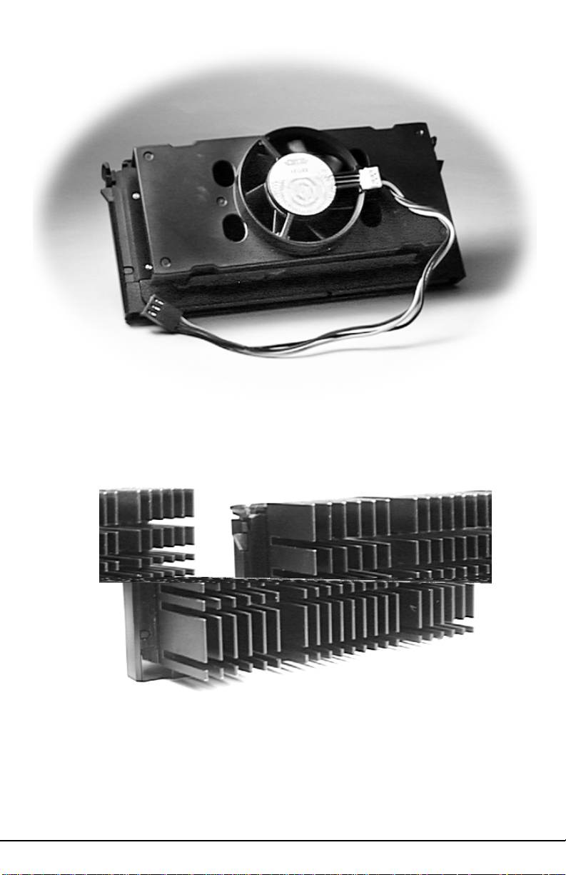
Pentium II Boxed (Active) CPU
Shown with Power Connector for Fan
Pentium II (Passive) CPU
Shown with Heatsink
8S1686D-001-01 http://www.tyan.com
Page 9

Chapter 2: Board Installation
2.1 Unpacking
2.1.1. Item Checklist
The motherboard package should contain the following:
S1686D Motherboard
One IDE 40 pin cable
One 34 pin floppy cable
User's Manual
2.1.2. Precautionary measures before handling the motherboard
Since the motherboard contains sensitive electronic components which can
easily be damaged by static electricity, the motherboard should be left in its
original packaging until it is ready to be installed.
Before you open the carton of your computer, do the following:
1. Make sure that you stand on an Anti-static mattress. (Do not stand on a rug or
carpet.)
2. It is also strongly recommended that you wear an anti-static strap. (Anti-static
straps can be purchased at computer hardware stores.)
3. With the power supply plugged in and the system turned off, touch an unpainted
area of the system chassis before handling the motherboard or any component.
Remember to repeat the above steps whenever you handle the motherboard or its
components.
2.1.3. Proper handling of the motherboard
After opening the S1686D motherboard carton, remove the board by holding its
edges. Place it on a grounded anti-static surface with the component side up.
Inspect the board for damage. Do not touch the bottom of the board. (Note: DO
NOT APPLY POWER TO THE BOARD IF IT HAS BEEN DAMAGED!)
2.2. Installation of the Motherboard
You are now ready to install your motherboard. The mounting hole pattern of the
S1686D matches the ATX system board specifications. Please install the board
in the chassis designed for a standard ATX board form factor.
9S1686D-001-01
Page 10
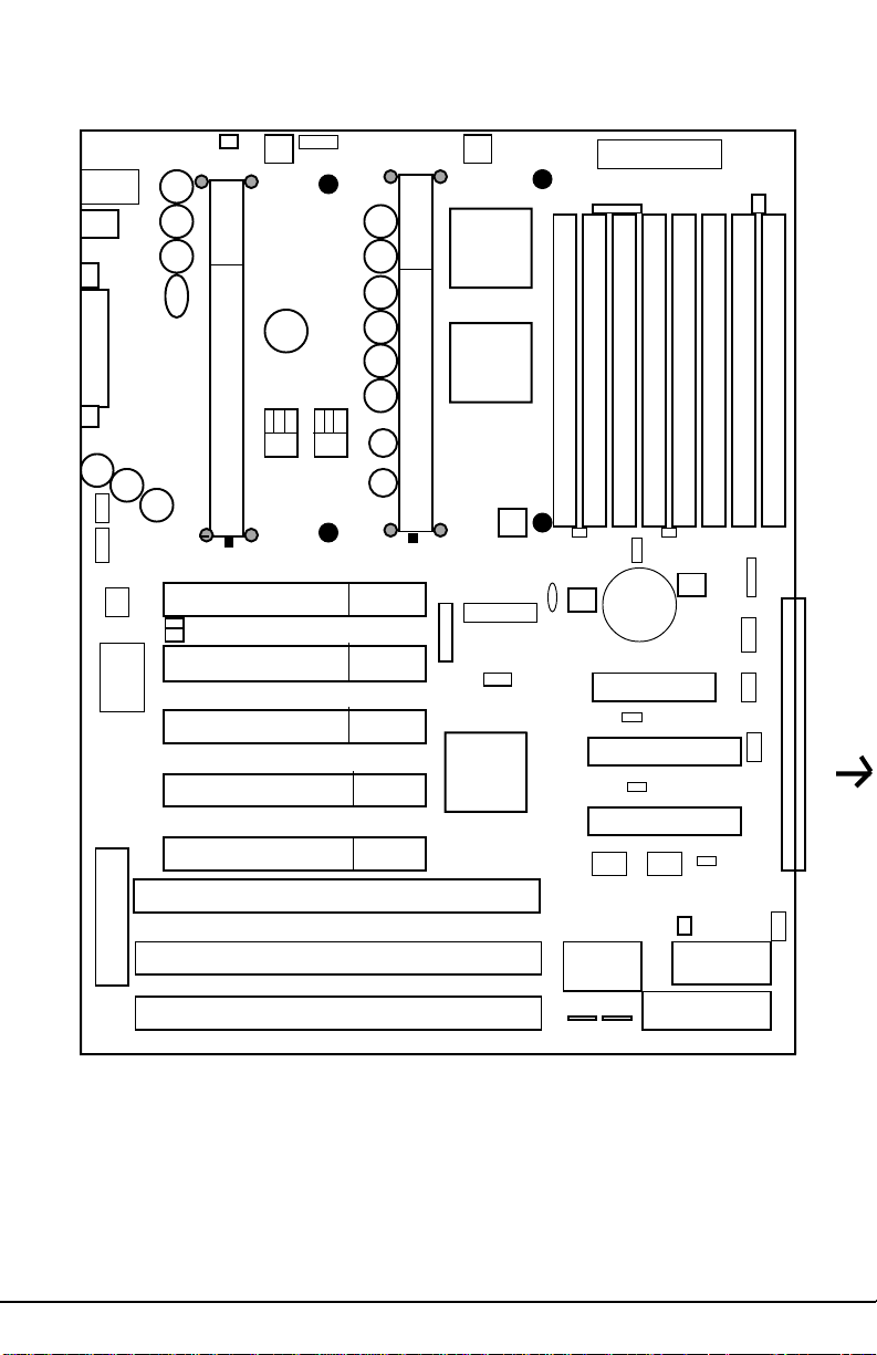
2.3.1 Motherboard Layout
MouseKB
J17J18
USB
J22
Com1
Parallel Port
1
J20
J1J2
CPUFan
CPU Ret.Bracket
CPU Ret.Bracket
U55
1
Voltage Convert
CPU
Ret.Brack
Heat Sink Hole
J3J4
1
J23
CPUFan
1
PCI
441FX
CPU Ret.Bracket
1
PCI
442FX
Power Supp.
JP1
J11-14
Heat Sink Hole
J6
J15J16
J7
Com2
Module(key) notch
1
J30J36
1
SMC
Keyboard
V oltage Regulator Module
Heat Sink Hole
CPU Ret.Bracket
CPU Ret.Bracket
Pentium II Second (SEC). Slot
Module(key) notch
PCI Slot 1
PCI Slot 2
J38
PCI Slot 3
PCI Slot 4
PCI Slot 5
ISA Slot 1
ISA Slot 2
ISA Slot 3
SIMM 1
SIMM 2
SIMM 3
J31J32
CPU Ret.Bracket
Pentium II Primary(SEC) Slot
J33J34
1
J37
1
PIIX3
1
J51J52J49J50 J5 5J53J54J47J48J46
J39
Heat Sink Hole
J24J25
FDD CON
1
Primary IDE
1
Secondary IDE
1
I/O APIC
J57J56
1
1
BIOS (CMOS)
AMI/AWARD
SIMM 5
SIMM 4
SIMM 6
J26J27
J35
J42
J44
RTC
SIMM 7
CON4
1
1
J28
1
KeyLock
J40
TB LED
J41
TBSW
J43
CHS Fan
J19
J60
SIMM 8
J29
(J29:See Pin Definition on P .1 1)
1
(For more information about this Motherboard, please visit our W eb Page and
Clickable motherboards at http://www.tyan.com/html/faq.html.)
10S1686D-001-01 http://www.tyan.com
Page 11
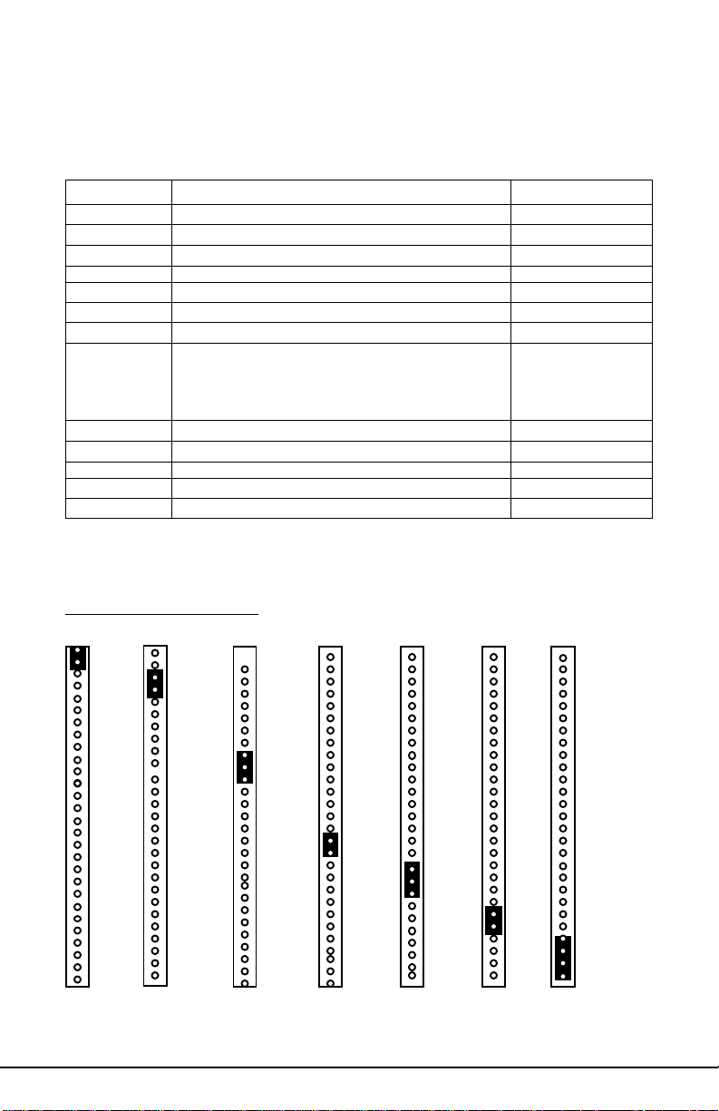
2.3.2 Summary of Jumper Settings
Refer to the following table for quick reference of jumper settings:
Jumper # Assignments Pg. #
J17 Keyboard Connector P10
J18 PS2 Mouse Connector P10
J20, J23 CPU Fan (Pin 2 is +12V) P10, P21
J19 CHS Fan (Chassis Fan) P10
J11, J12, J37 Bus Speed P12
J13-J16, J24-27 DRAM Voltage Select (Do not Change) P12
J22 Universal Serial Bus P10
J29 Pins 1,2: Power on, Pins 3,4: EXTSMI
Pins 8-10: IR2 P14,15,16
Pins15,16: IDE LED, Pins18-20: Power LED
Pins22,23: Reset, Pins24-27: Speaker
J30, J36 I/O Select P13
J31-34 CPU Speed Settings P12
J49,50 LM78 IRQ Select P13
J44 CMOS Reset P12,P17
JP1 Magic Packet Connector P14
Block J29 Pin Assignments
Power on: Pins 1,2 (close)
(Cover Pins1&2 with a jumper cap to short the circuit between Pins.)
EXTSMI: Pins 3,4(close)
IR2: Pins8-10(close)
(Cover Pins3,4 with a jumper cap to short the circuit between Pins.)
(Cover Pins8-10 with a jumper cap and short the circuit between pins.)
IDE LED: Pins 15,16 (close)
Power LED: Pins 18-20 (close)
(Cover Pins15,16 with a jumper cap and short the circuit between pins.)
11S1686D-001-01
(Cover Pins18-20 with a jumper cap and short the circuit between pins.)
Reset: Pins 22, 23 (close)
Speaker:Pins24-27
(Cover Pins22,23 with a jumper cap to short the circuit between pins.)
(Cover Pins24-27 with a jumper cap to short the circuit between Pins.)
Page 12
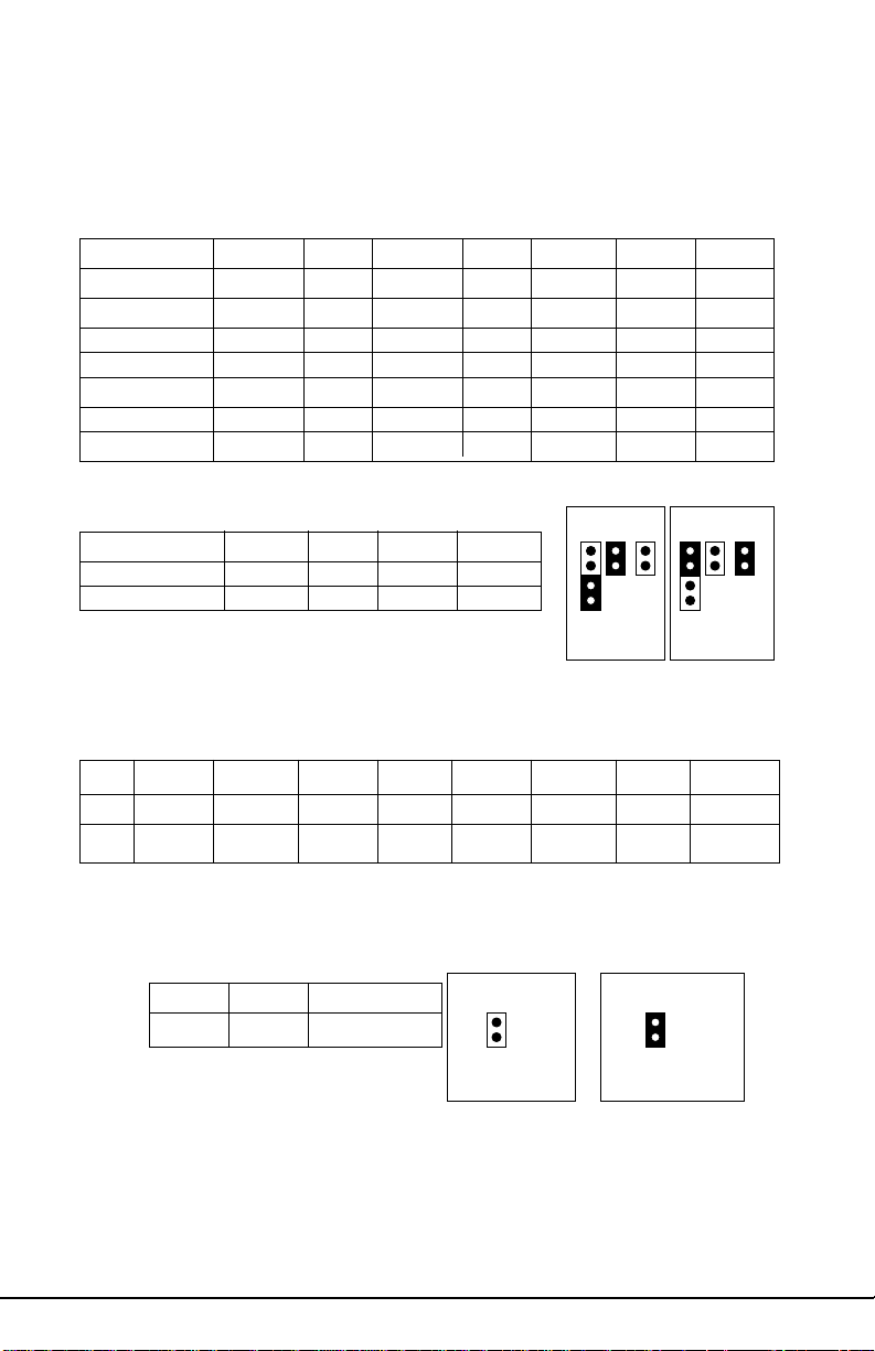
23.3 Jumper Settings
CPU Speed Settings for Pentium II and Pentium Pro Processors:
CP U J31 J32 J33 J34 J37 J12 J1 1
150MHz Off On On On 3-4 On Off
166MHz Off On On On 1-2 Off On
180MHz On Off On On 3-4 On Off
200MHz On Off On On 1-2 Off On
233MHz Off Off On On 1-2 Off On
266MHz On On Off On 1-2 Off On
300MHz Off On Off On 1-2 Off On
Bus Speed
HOST SP PCI SP J37 J12 J11
Pin 1 2 3 4
J37 J12 J11 J37J12 J11
60MHz 30MHz 3-4 On Off
66MHz 33MHz 1-2 Off On
CPU60MHz
PCI30MHz
CPU66MHz
PCI33MHz
SIMM V oltage Select (* Do not change--set at Factory!!)
J15 J16 J26 J27 J13 J14 J24 J25
5V Close Close Close Close Open Open Open Open
3.3V Open Open Open Open Close Close Close Close
CMOS Reset: J44 (Always reset after changing BIOS)
CMOS Normal Clear (Reset) Normal Clear (reset)
Pin 1 2
Pin 1 2
J4 4 Open Close
J44 J44
12S1686D-001-01 http://www.tyan.com
Page 13

I/O Select
J30 J36
1-2 2-3 1-2 2-3
COMPort Close Open Close Open
Inf.Red Open Close Open Close
LM78 IRQ Select
IRQ# J49 J50
5 Open 1 - 2
7 Open 2 - 3
9 1 - 2 Open
1 1 2 - 3 Open
J30 J36
COM Port
Pin 1 2 3
J30 J36
Infra Red
Pin 1 2 3
13S1686D-001-01
Page 14

Connectors:
Magic Packet Connector: JP1
Pin# Signal
1 SB5V
2 Ground
3 SB5V
4NC
5 W ake Up Lan
6 PWROK
Block J29: (Refer to Page 11 for more information.)
Pin No. Definition
1 & 2 Power On
3&4 EXTSMI
8-10 IR2
15&16 IDE LED
18-20 Power LED
22 & 23 Reset
24-27 Speaker
J17: Keyboard Connector
J18: PS/2 Mouse Connector
J22: Universal Serial Bus Ports
CON 5: FDD CON
CON 6: Primary IDE
CON 7: Secondary IDE
CON2: LPT1
CON3: COM1
CON1: COM2
14S1686D-001-01 http://www.tyan.com
Page 15

Speaker Connector: J29 pins 24-27
Pin Assignments
24 +5V
25 ground
27 Speaker data
(Refer to Page 11 for more information.)
15S1686D-001-01
Page 16

2.4 CMOS RTC
The CMOS RTC includes an internal battery and real time clock circuit
which provides the date and the time, and the CMOS Chipset Default
Register for the system. Normally , the life span of a R TC internal battery is
more than 10 years. This R TC chip cannot be field upgraded and can only
be changed at a Tyan repairing facility.
2.5 Installing Cables and Connectors
2.5.1 Speaker Connector Installation (J29)
Your S1686D board provides a 4-Pin header to connect the speaker. The
speaker is connected to pins 24-27 of J29. (Refer to Page 10 and Page 11
for detailed information.)
2.5.2 Hardware Reset Switch Connector Installation (J29)
The RESET switch on your case's display panel provides you with the
HARDWARE RESET function which is the same as power on/off. The
system will do a cold start after the RESET switch is pushed by the user.
The RESET switch is a 2 pin connector and should be installed on pins
22 and 23 on J29. (Refer to Page 10 and Page 11 for detailed information.)
2.5.3 IDE LED Connector Installation (J29)
Y our S1686D board provides a 2-Pin header to connect the IDELED cable.
When connected, the IDELED light on the panel of the case flashes if a
IDE activity is detected. The cable is connected to pins 15 & 16 of J29.
(Refer to Page 10 and Page 11 for detailed information.)
2.5.4 Power LED Connector Installation (J29)
The S1686D board also provides a 3-Pin header to connect the Power LED
cable. When connected, the Power LED light on the panel of the case
indicates power on/off of the system. The cable is connected to pins 18-20
of J29. (Refer to Page 10 and Page 11 for detailed information.)
2.5.5 IR2 Connector Installation (J29)
The S1686D board provides a 3-Pin connector (Pins 8-10 of J29) for the
IR2 cable which connects to a Homing Device on the back of the case.
When activated, the Homing Device will send out IR signals to remote I/O
IR devices. (Refer to Page 10 and Page 11 for detailed information.)
16S1686D-001-01 http://www.tyan.com
Page 17

2.5.6 Flash ROM-Jumper J56
The S1686D uses flash memory to store BIOS Setups. It can be updated
as new versions of the BIOS become available. The flash utility will guide
you through the process step by step. However, we do not recommend
that you flash the onboard BIOS. This procedure should only be
done by a qualified technician or a Tyan technical support engineer.
J56 determines which type of Flash EPROM is used. This jumper has been
set to match the onboard BIOS chip. The factory default for the S1686D
is on pins 1-2(5V). Depending on the type of EPROM used, some boards
will have J56 on pins 2-3(12V). (Refer to Page 13 for more information.)
*****************************************************
Warning!!
*Do not change J56--(It has been pre-configured at the factory.)
2.5.7 Hardware CMOS & Password Reset (J44)
If you are locked out of your system because you have forgotten your
password, or you have set the CMOS incorrectly, follow the instructions
below.
a. Power off the system.
b. Short J44 by covering Pin 1 and Pin 2 of J44 with a jumper cap
and short the circuit between these two pins.
c. Wait for 5 seconds, and, then, remove the jumper cap from J44.
d. Apply power to the system.
By following the above procedures, the password and CMOS will be reset
to BIOS defaults.
17S1686D-001-01
Page 18

2.6 DRAM Installation
The S1686D uses a 64-bit data path from memory to the CPU which will
accommodate up to 512MB of RAM. The motherboard supports FPM
(Fast Page Mode), EDO (Extended Data Out), ECC (Error Correcting
Code), and Parity 72-pin SIMMs. The following table shows some of the
available memory configurations.
Bank 0 Bank 1 Bank 2 Bank 3 T otal
4MBx2 none none none 8MB
8MBx2 none none none 16MB
4MBx2 4MBx2 none none 16MB
8MBx2 8MBx2 none none 32MB
4MBx2 4MBx2 4MBx2 4MBx2 32MB
16MBx2 none none none 32MB
16MBx2 16MBx2 none none 64MB
32MBx2 none none none 64MB
64MBx2 none none none 128MB
16MBx2 16MBx2 16MBx2 16MBx2 128MB
32MBx2 32MBx2 none none 128MB
32MBx2 32MBx2 32MBx2 none 192MB
32MBx2 32MBx2 32MBx2 32MBx2 256MB
64MBx2 64MBx2 none none 256MB
128MBx2 none none none 256MB
64MBx2 64MBx2 64MBx2 none 384MB
64MBx2 64MBx2 64MBx2 64MBx2 512MB
128MBx2 128MBx2 none none 512MB
18S1686D-001-01 http://www.tyan.com
Page 19

2.7 Level 2 Cache Memory/SRAM Memory
The S1686D's L2 Cache Memory is built into the Intel Pentium II CPU.
There are no L2 Cache Memory slots or SRAM slots on the motherboard.
2.8 VRM (Voltage Regulator Module)
The CPU will program the VRM for the correct voltage needed. No
jumper settings are required. The S1686D has two built-in VRMs on
board.
2.9 Peripheral Device Installation
Install the motherboard after you have checked all of the jumper settings.
Also be sure to check all connectors thoroughly and read the technical
manuals that come with your peripheral cards before you install your addon peripheral cards.
If a PCI-Bus interface card is to be installed in the system, any one of the
five PCI-Bus slots will support either a Master or a Slave device.
2.10 Connecting the Power Supply and On/Off Switch
The system is configured for a standard ATX power supply. The ATX
connectors can only be plugged in one way and should install easily .
19S1686D-001-01
Page 20

Chapter 3: CPU Installation and Removal
Pentium II (233 through 300MHz) and Pentium Pro Processors (150 through
200 MHz) can be used on the S1686D. Please refer to section 2.3 for the
correct CPU jumper settings. Although the S1686D motherboard is designed as a dual CPU system, it will also function with a single CPU.
The S1686D board provides two slots for Pentium II Processors--(Pentium
II Primary and Secondary Slots). If only one CPU is used, the CPU should
be plugged into the Primary Slot. However, when two CPUs are used,
these CPUs should be of the same speed and type.
Caution!! The CPU is a sensitive electronic component which can be easily
damaged by static electricity. Do not touch the CPU pins with your fingers.
3.1 Installation of Pentium II Boxed (Active) Processors
(Note: Active Processors are equipped with cooling fans. When installing an
Active CPU, you also need to connect the cooling fan cable to its connector.)
Installing CPU Retention Modules
1. Installation of a Pentium II Active Processor requires a CPU
Retention Module, which is first secured onto the motherboard. (Refer to
the motherboard layout on Page 10.)
2. To attach the Retention Module, place the motherboard on a flat
surface.
3. Locate
the key pin on one end
of the Pentium II Slot on the
board. Then carefully line up the
key notch on the Retention Module
with the key pin on the Pentium II
Slot. (The key pin on the Pentium
II Slot indicates the correct orientation of the CPU.)
Pentium II Slot Connector
and Key Pin
20S1686D-001-01 http://www.tyan.com
Page 21

4. Drop the Retention Module down
over the Pentium II Slot so that the Retention
Module seats flat against the motherboard.
Tighten the screws in a clockwise manner to
secure the module to the board. (Warning- Do
not overtighten the screws as you may
damage the module and /or the motherboard.)
Retention Module
3.2 Installing CPUs
5. When the Retention Module is securely installed, you are ready to plug
the CPU into the Retention Module. Make sure that the CPU's Cooling
Fan is turned away from the I/O connectors before you plug the CPU
into the CPU module.
6. Press firmly on the CPU until you hear a "click". The Pentium II CPU
will make a clicking sound when it is fully locked into the Retention
Module.
7. After the CPU is securely seated on the Retention Module in the
Pentium II Slot, connect the CPU's Cooling Fan cable to the Cooling Fan
Power Connector on the board.
3.3 Installing CPU Cooling Fans
8. Locate the Cooling Fan Connectors. (2 Connectors: J20 and J23--1 for
each CPU.)
9. Plug the CPU's Cooling Fan cable into the CPU Fan Connector on the
board. Make sure that the black wire of the cable is plugged into Pin 1 of
the connector. (Refer to Pin 1 marked on the layout on P.10.) (Pin
assignments: Pin 1: ground--black, Pin 2: 12V--Red, Pin 3: Signal-Y ellow .)
21S1686D-001-01
Page 22

3.4 Installation and Removal of Pentium II Passive Processors
(Unlike Active Processors, Passive Processors are not equipped with
cooling fans. Passive
Processors are equipped
with heat sinks instead.)
Each CPU package
should also contain the
following:
CPU Retention Module
(x1)
Heat-sink Retention
Bracket with mounting
Pentium II Passive CPU Module
locks (x1)
Mounting Attach-mounts (x 2)
Heat-sink Lock (x1)
3.4.1 Installing CPU
Retention Modules
1. When installing the CPU
Retention Module, make sure
that you have the appropriate end of the module lined up with the key
notch on the Pentium II Slot connector. This will ensure that the
module is installed properly .
2. Before tightening the screws, make certain that the module is flush
against the motherboard. If one end of the module is raised above the
board, check the orientation of the module.
3. Install the module on the board by turning the screws in a clockwise
direction. (Do not over tighten the screws).
Retention Module
22S1686D-001-01 http://www.tyan.com
Page 23

3.4.2 Installing Heat-sink Mounting Brackets
1. The heat-sink mount has two pins on the bottom and 4 pins on the top.
Notice that the bottom two pins are of different sizes. The size of the
pins and the holes in the motherboard will determine the correct orientation. A correctly installed bracket can be verified by noting the 4 pins on
the top. These 4 pins should be closest to the Pentium II CPU slot.
2. Insert the heat-sink mount into the holes on the motherboard. When
the bracket is properly inserted into the holes on the motherboard, you will
hear a clicking noise .
3. Lock the heat-sink mount to the board by inserting the two mounting
locks into the pins of the heat-sink mounting bracket which are now
below the motherboard. There will be a
click when the locks are securely
fastened.
3.4.3 Installing Pentium II Passive
Processors
1. Align the CPU with the CPU retention
module. Make sure the heat-sink is lined
Mounting Bracket & Locks
up with the heat-sink mount bracket. If you put the CPU in the wrong
way, you may damage the CPU, the motherboard, and/or the socket.
2. Slowly press down on the CPU module until the CPU locks into place.
A clicking noise will be heard when the CPU is locked securely into the
module.
3.4.4 Installing Heat-sink Locks
The heat-sink lock has 4 notches which will correspond to the 4 pins on
the heat-sink mounting bracket. Gently slide the lock between the heatsink onto the heat-sink mounting bracket until both sides of the lock are
firmly secured. A clicking sound will be heard when the lock is securely
fastened to the heat-sink mounting bracket. To remove the lock from the
heat-sink mounting bracket, gently press the ends of the locks inward and
pull.
23S1686D-001-01
Page 24

Heat-Sink Lock
3.4.5 Removing Pentium II Passive Processors and CPU
Retention Modules
To remove the CPU, move the locks to the center of the CPU. A
click will be heard when the CPU has been unlocked. Gently pull up
on the CPU, taking care not to bend the motherboard or the CPU
Retention Module.
3.4.6: Removing Heat-Sink Locks
To remove the lock from the Retention Bracket, gently press the ends
of the locks inward and pull.
24S1686D-001-01 http://www.tyan.com
Page 25

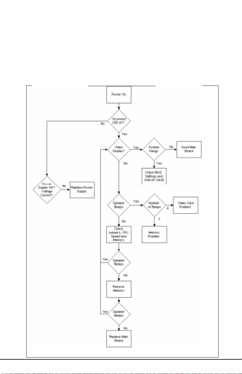
Chapter 4: Troubleshooting
4.1 Troubleshooting Procedures
Use the following procedures to troubleshoot your system. If you have followed
all of the procedures below and still need assistance, refer to the "T echnical
Support Procedures" and/or "Returning Merchandise for Service" section(s) in
this chapter.
No-Video
If you do not have video, follow the Troubleshooting Flowchart on the next
page.
1. Check for missing jumpers or improper installation of the ROM BIOS.
2. Make sure the video card and its jumper setting (as appropriate) match the
monitor type.
3. Check to make sure that all peripheral cards are properly installed in their
slots.
4. Check for incorrect cache memory jumper settings that may prevent accurate
detection of memory.
5. The I/O Bus speed should be running at the standard speed of 8 MHz.
6. Use the speaker to determine if any beep codes exist. Refer to Addendum A
and Addendum B for details about beep codes.
Note: If you are a system integrator, VAR, or OEM, a POST diagnostics car d is
recommended for Port 80h codes. (Please visit our Web Site for detailed
information.)
Memory Error/Parity Error
If you encounter memory or parity errors, follow the procedures below .
1. Check to determine if SIMM modules are improperly installed.
2. Make sure that different types of SIMMs have not been installed in the
same bank. (eg. a mixture of 265KB x 9 and 1 MB x 9)
25S1686D-001-01
Page 26
3. Determine if different speeds of SIMMs have been installed in the
same or different banks, and the BIOS setup is configured for the
slowest speed of RAM used. It is recommended to use the same
RAM speed for SIMMs in different banks Finally, check for bad SIMM
modules and Chips
T r oubleShooting Flowchart
26S1686D-001-01 http://www.tyan.com
Page 27

Losing the System's Setup Configuration
1. Make sure that you are using a high quality power supply. A poor quality
power supply may cause the system to lose its CMOS setup.
2. Determine if the Dallas Battery is bad. If it is bad, replace it with a good one.
(The following steps will help you determine if the RTC is bad: a. T urn on the
system and set the system clock. b. Let the system run for more than 6
hours. c. Check the system clock to see if it has accurate timing.
If the system timing is off, it is very possible that the R TC battery is bad.)
3. If the above steps do not fix the Setup Configuration problem, contact your
vendor for repair.
4.2 Technical Support Procedures
Be sure to go through the "Troubleshooting Procedures" section in this Chapter,
and visit our W eb site for additional information before calling Technical
Support. (T yan's Web Site address is: http://www.tyan.com.)
If the problem is still not resolved, have the following information ready before
you call for technical support:
1. System Board Serial Number
2. CPU Serial Number
3. Invoice Number, Date
4. Purchase Form
5. Sale's Person's name
6. Product Configurations
4.3 Returning Merchandise for Service
A receipt or a copy of your invoice marked with the date of purchase is required
before any warranty service will be rendered. You can obtain service by calling
the manufacturer for a Return Merchandise Authorization (RMA) number. The
RMA number should be prominently displayed on the outside of the shipping
carton and mailed prepaid, or hand-carried to the manufacturer. Shipping and
handling charges will be applied for all orders that must be mailed when service is
complete. During the warranty period, contact your distributor first for any
product problems.
This warranty only covers normal consumer use and does not cover damages
incurred in shipping or from failure due to the alteration, misuse, abuse, or
improper maintenance of products.
27S1686D-001-01
Page 28

Appendix: LM78 System Hardware Monitor and LANDesk Client
Manager (LDCM)
To enhance the performance of your computer system, Tyan has incorporated National Semiconductor's LM78 Microprocessor System Hardware Monitor and LANDesk Client Manager (LDCM) into the S1686D
board design. The LM78 is an Integrated Data Acquisition system,
designed to monitor power supply voltages, temperatures, and fan speeds.
T o achieve this purpose, the LM78, a hardware monitor component, has
an on-chip temperature sensor, 5 positive analog inputs, two inverting
inputs and an 8-bit ADC. In addition, the LM78 also provides ISA and
Serial Bus Interfaces. A 32-byte auto-increment RAM is provided for
POST (Power On Self Test) code storage.
Features
The LM78 includes the following features:
* Temperature sensoring
* 5 positive voltage inputs
* 2 op amps for negative voltage monitoring
* 3 fan speed monitoring inputs
* Input for additional temperature sensors
* Chassis Intrusion Detector Input
The software program-- LDCM (LANDesk Client Manager) is used as
the LM78's drivers to accomplish monitoring computers' temperatures
and voltages. The LDCM Drivers use the LM78 to monitor critical
hardware components and enable remote sensing and diagnostics of the
system Board. Thus, by implementing both National Semiconductor's
LM78 and LDCM in the S1682D system, T yan provides you with the
best quality board possible on the market.
For more information, please refer to the Web Page.
28S1686D-001-01 http://www.tyan.com
Page 29

Compliance Information Statement
( Declaration of Conformity Procedure-DOC)
Notice for the USA
FCC Part 15: This Device complies with Part 15 of the FCC Rules.
Operation is subject to the following conditions:
1) this device may not cause harmful interference, and
2) this device must accept any interference received
including interference that may cause undesired operation.
If this equipment does cause harmful interference to radio or television
reception, which can be determined by turning the equipment off and on,
the user is encouraged to try one or more of the following measures:
w Reorient or relocate the receiving antenna.
w Increase the separation between the equipment and receiver.
w Connect the equipment into an outlet on a circuit different from that of the
receiver connected.
w Consult the dealer or an experienced radio/TV technician for help.
Notice for Canada
This apparatus complies with the Class "B" limits for radio interference as
specified in the Canadian Department of Communications Radio Interference
Regulations.
Cet appareil est conforme aux normes de CLASSE "B" d' interference radio
tel que spec' cifie' par le Ministe're Canadien des Communications dans les
re'glements d'interfe'rence radio.
Notice for Europe (CE Mark)
This product is in conformity to the Council Directive 89/336/EEC, 92/31/EEC
(EMC)
Acknowledgment
Information presented in this publication has been carefully checked for
reliability; however, no responsibility is assumed for inaccuracies. The
information contained in this document is subject to change without
notice.
Trademarks
A ward BIOS/Flash are trademarks of A ward Software International Inc.
AMI BIOS is a trademarks of American Megatrends Inc.
IBM,PC,A T ,PS/2 are esiademarks of IBM Corporation
INTEL,Pentium are esiademarks of Intel Corporation.
29S1686D-001-01
Page 30

Tyan Pentium II Motherboards
Addendum A
AMI BIOS CMOS Setup
User’s Guide
for
Intel 440FX Series PCIset
Based on the 7/15/95 V6.26 Core AMIBIOS.
Use with AMIBCP Version 6
Page 31

Trademarks
Intel , Pentium II, and Pentium are registered trademarks of Intel Corporation.
MS-DOS and Microsoft are registered trademarks of Microsoft Corporation. Microsoft Windows, Windows 95, and Windows NT are
trademarks of Microsoft Corporation.
Weitek is a registered trademark of Weitek Corporation.
IBM, AT, VGA, PS/2, OS/2, and EGA are registered trademarks of International Business Machines Corporation. XT and CGA are
trademarks of International Business Machines Corporation.
Revision History
4/3/97 Initial release.
-----------------------------------------------------------------------------------------------------------------------------------------------Pentium II Motherboards AMI BIOS Setup -Page 2-
Page 32

Table of Contents
1 Introduction .............................................................4
2 Standard Setup........................................................7
3 Advanced Setup....................................................10
4 Chipset Setup........................................................16
5 Power Management Setup....................................21
6 PCI/PnP Setup .......................................................25
7 Peripheral Setup....................................................28
8 A Few Words on Flash BIOS Upgrades...............31
-----------------------------------------------------------------------------------------------------------------------------------------------Pentium II Motherboards AMI BIOS Setup -Page 3-
Page 33

1 Introduction
This manual documents the setup requirements of the AMI BIOS for Tyan’s PentiumII motherboards,
which supports Intel’s Pentium II and Pentium Pro Processors. This system configuration information is
stored in the battery-backed RAM and is retained even if the power of your system is turned off. The AMI
BIOS Setup Utility can also be accessed by the user during the Power-On -Self-Test (POST).
The AMI BIOS supports the following:
1. Plug and Play (v. 1.0A) and ESCD (Extended System Configuration Data)
2. EPA Green PC (v. 1.03)
3. APM (Advanced Power Management v.1) via SMI (System Management Interrupt)
4. PCI Bus
5. DRAM, EDO, FPM, ECC
6. Flash ROM
How Data Is Configured
AMIBIOS provides a Setup utility in the CMOS RAM and can be accessed by pressing <Del> at the
appropriate time during system boot. The Setup utility configures data in the CMOS RAM.
-----------------------------------------------------------------------------------------------------------------------------------------------Pentium II Motherboards AMI BIOS Setup -Page 4-
Page 34

Types of AMIBIOS Setup
Types of
Setup
Standard Sets time, date, hard disk type, types of floppy
drives, monitor type, and if keyboard is installed.
Advanced Sets Typematic Rate and Delay, Above 1 MB
Memory Test, Memory Test Tick Sound, Hit <Del>
Message Display, System Boot Up Sequence, and
many others.
Chipset Sets chipset-specific options and features.
Power
Management
PCI/PnP Sets options related to the PCI bus and Plug and
Peripheral Controls I/O Controller-related options.
Controls power conservation options.
Play options.
Description
-----------------------------------------------------------------------------------------------------------------------------------------------Pentium II Motherboards AMI BIOS Setup -Page 5-
Page 35
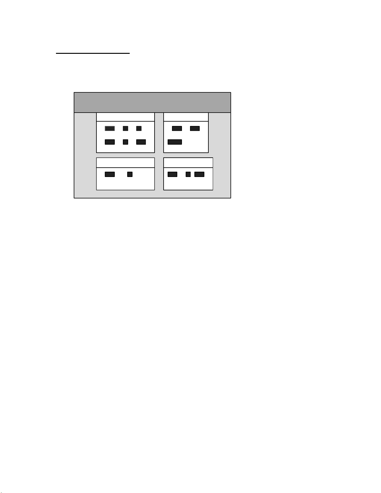
AMI BIOS Main Menu
The following screen represents the Main Menu of BIOS Setup types:
AMI BIOS Setup
© 1996, American Megatrends Inc.
Setup Security
Standard Advanced Chipset Supervisor User
PowerMgmt PCI/PnP Peripheral Anti-Virus
Utility Default
Detect IDE Language Original Optimal Fail-safe
Alt+H:Help
-----------------------------------------------------------------------------------------------------------------------------------------------Pentium II Motherboards AMI BIOS Setup -Page 6-
Page 36

2 Standard Setup
Select the AMIBIOS Setup options by choosing Standard Setup from the AMIBIOS
Setup main menu. Standard Setup options are described below.
Floppy Drive A: and B: Move the cursor to these fields via ↑ and ↓ and select the floppy type. The
settings are 360 KB 5¼ inch, 1.2 MB 5¼ inch, 720 KB 3½ inch, 1.44 MB 3½ inch, or
2.88 MB 3½ inch.
Primary Master
Primary Slave
Secondary Master
Secondary Slave Select these options to configure the drive named in the option. Select Auto Detect IDE
to let AMIBIOS automatically configure the drive. A screen with a list of drive
parameters appears. Click on OK to configure the drive.
Type How to Configure
SCSI
IDE
CD-ROM
Standard
MFM
Non-
Standard
MFM
Select Type. Select Not Installed from the drive parameter
screen. The SCSI drivers provided by the SCSI manufacturer
should allow you to configure the SCSI drive.
Select Type. Select Auto to let AMIBIOS determine the
parameters. Click on OK when AMIBIOS displays the drive
parameters. Select LBA Mode. Select On if the drive has a
capacity greater than 540 MB.
Select Block Mode. Select On to allow block mode data
transfers. Select 32-Bit Mode. Select On to allow 32-bit data
transfers. Select the PIO Mode. It is best to select Auto to allow
AMIBIOS to determine the PIO mode. If you select a PIO mode
that is not supported by the IDE drive, the drive will not work
properly. If you are absolutely certain that you know the drive’s
PIO mode, select PIO mode 0 - 5, as appropriate. *The default
setting for this item is “4”.
Select Type. Select CDROM. Click on OK when AMIBIOS
displays the drive parameters.
Select Type. You must know the drive parameters. Select the
drive type that exactly matches your drive’s parameters.
Select Type. If the drive parameters do not match the drive
parameters listed for drive types 1 - 46, select User and enter
the correct hard disk drive parameters.
-----------------------------------------------------------------------------------------------------------------------------------------------Pentium II Motherboards AMI BIOS Setup -Page 7-
Page 37

Standard Setup, Continued
Entering Drive Parameters You can also enter the hard disk drive parameters. The drive parameters are:
Parameter Description
Type The number for a drive with certain identification
parameters.
Cylinders The number of cylinders in the disk drive.
Heads The number of heads.
Write
Precompensation
Landing Zone This number is the cylinder location where the heads
Sectors The number of sectors per track. MFM drives have 17
Capacity The formatted capacity of the drive is the number of
The actual physical size of a sector gets progressively
smaller as the track diameter diminishes. Yet each
sector must still hold 512 bytes. Write
precompensation circuitry on the hard disk
compensates for the physical difference in sector size
by boosting the write current for sectors on inner
tracks. This parameter is the track number on the disk
surface where write precompensation begins.
normally park when the system is shut down.
sectors per track. RLL drives have 26 sectors per
track. ESDI drives have 34 sectors per track. SCSI
and IDE drives have even more sectors per track.
heads times the number of cylinders times the number
of sectors per track times 512 (bytes per sector).
Cont’d
-----------------------------------------------------------------------------------------------------------------------------------------------Pentium II Motherboards AMI BIOS Setup -Page 8-
Page 38

Standard Setup, Continued
Hard Disk Drive Types
Type Cylinders Heads Write
1 306 4 128 305 17 10 MB
2 615 4 300 615 17 20 MB
3 615 6 300 615 17 31 MB
4 940 8 512 940 17 62 MB
5 940 6 512 940 17 47 MB
6 615 4 65535 615 17 20 MB
7 462 8 256 511 17 31 MB
8 733 5 65535 733 17 30 MB
9 900 15 65535 901 17 112 MB
10 820 3 65535 820 17 20 MB
11 855 5 65535 855 17 35 MB
12 855 7 65535 855 17 50 MB
13 306 8 128 319 17 20 MB
14 733 7 65535 733 17 43 MB
16 612 4 0 663 17 20 MB
17 977 5 300 977 17 41 MB
18 977 7 65535 977 17 57 MB
19 1024 7 512 1023 17 60 MB
20 733 5 300 732 17 30 MB
21 733 7 300 732 17 43 MB
22 733 5 300 733 17 30 MB
23 306 4 0 336 17 10 MB
24 925 7 0 925 17 54 MB
25 925 9 65535 925 17 69 MB
26 754 7 754 754 17 44 MB
27 754 11 65535 754 17 69 MB
28 699 7 256 699 17 41 MB
29 823 10 65535 823 17 68 MB
30 918 7 918 918 17 53 MB
31 1024 11 65535 1024 17 94 MB
32 1024 15 65535 1024 17 128 MB
33 1024 5 1024 1024 17 43 MB
34 612 2 128 612 17 10 MB
35 1024 9 65535 1024 17 77 MB
36 1024 8 512 1024 17 68 MB
37 615 8 128 615 17 41 MB
38 987 3 987 987 17 25 MB
39 987 7 987 987 17 57 MB
40 820 6 820 820 17 41 MB
41 977 5 977 977 17 41 MB
511 981 5 981 981 17 41 MB
43 830 7 512 830 17 48 MB
44 830 10 65535 830 17 69 MB
45 917 15 65535 918 17 114 MB
46 1224 15 65535 1223 17 152 MB
Precompensation
Landing
Zone
Sectors Capacity
-----------------------------------------------------------------------------------------------------------------------------------------------Pentium II Motherboards AMI BIOS Setup -Page 9-
Page 39

3 Advanced Setup
The Advanced Setup settings, designed for the Intel 440FX chipset, are described in this
chapter. Select Advanced Setup from the AMIBIOS Setup main menu to display the
Advanced Setup options.
Default Settings
Every option in AMIBIOS Setup contains three sets of values: Fail-Safe, Original, and
Optimal Default settings. Do not change any default values set by your manufacturer,
unless you thoroughly understand the functions of the items you are changing.
Optimal Defaults The Optimal default values provide optimum performance settings for all devices and
system features.
Fail-Safe Defaults The Fail-Safe default settings consist of the safest set of parameters. Use them if the
system is behaving erratically. They should always work but do not provide optimal
system performance characteristics.
Original Defaults This option allows the user to restore the original defaults and allows the user to use
the last-saved values as new default values.
------------------------------------------------------------------------------------------------------------------------------------------------
Pentium II Motherboards AMI BIOS Setup -Page 10-
Page 40

Advanced Setup
Quick Boot Set this option to Enabled to instruct AMIBIOS to boot quickly when the computer is
powered on. This option replaces the old Above 1 MB Memory Test Advanced Setup
option. The settings are:
Setting Description
Disabled
Enabled
The Optimal default setting is Enabled and the Fail-Safe default setting is Disabled.
AMIBIOS test all system memory. AMIBIOS waits up to 40
seconds for a READY signal from the IDE hard disk drive.
AMIBIOS waits for .5 seconds after sending a RESET signal
to the IDE drive to allow the IDE drive time to get ready
again. AMIBIOS checks for a <Del> key press and runs
AMIBIOS Setup if the key has been pressed.
AMIBIOS does not test system memory above 1 MB.
AMIBIOS does not wait up to 40 seconds for a READY
signal from the IDE hard disk drive. If a READY signal is
not received immediately from the IDE drive, AMIBIOS
does not configure that drive. AMIBIOS does not wait for .5
seconds after sending a RESET signal to the IDE drive to
allow the IDE drive time to get ready again.
You cannot run AMIBIOS Setup at system boot, because
there is no delay for the Hit <Del> to run Setup message.
1st Boot Device This option sets the type of device for the first boot drives that the AMIBIOS attempts to
boot from after AMIBIOS POST completes. The settings are Disabled, Floptical,
Floppy, SCSI, IDE-0, IDE-1, IDE-2, IDE-3 or CDROM The Optimal and Fail-Safe
default settings are Floppy.
2nd Boot Device This option sets the type of device for the second boot drives that the AMIBIOS attempts
to boot from after AMIBIOS POST completes. The settings are Disabled, Floppy,
Floptical, IDE-0 or CDROM. The Optimal and Fail-Safe default settings are IDE-0.
Cont’d
------------------------------------------------------------------------------------------------------------------------------------------------
Pentium II Motherboards AMI BIOS Setup -Page 11-
Page 41

Advanced Setup, Continued
3rd Boot Device This option sets the type of device for the third boot drives that the AMIBIOS attempts
to boot from after AMIBIOS POST completes. The settings are Disabled, CD-ROM,
Floppy, Floptical, or IDE-0. The Optimal and Fail-Safe default settings are CDROM.
4th Boot Device This option sets the type of device for the fourth boot drives that the AMIBIOS attempts
to boot from after AMIBIOS POST completes. The settings are Disabled, CD-ROM,
IDE-0, Floptical, or Floppy. The Optimal and Fail-Safe default settings are Disabled.
S.M.A.R.T. For Hard Disks Set this option to Enabled to permit AMIBIOS to use the SMART (System
Management and Reporting Technologies) protocol for reporting server system
information over a network. The settings are Enabled or Disabled. The Optimal and
Fail-Safe default settings are Disabled.
Cont’d
------------------------------------------------------------------------------------------------------------------------------------------------
Pentium II Motherboards AMI BIOS Setup -Page 12-
Page 42

Advanced Setup, Continued
Boot Up Num Lock Set this option to Off to turn the Num Lock key off when the computer is booted so
you can use the arrow keys on both the numeric keypad and the keyboard. The settings
are On or Off. The default settings are On.
Floppy Drive Swap Set this option to Enabled to permit drives A: and B: to be swapped. The settings are
Enabled or Disabled. The default settings are Disabled.
PS/2 Mouse Support Set this option to Enabled to enable AMIBIOS support for a PS/2-type mouse. Pins
2-3 of the PS/2 Mouse Selector jumper on the motherboard must be shorted together to
enable PS/2 mouse support. The settings are Enabled or Disabled. The Optimal and
Fail-Safe default settings are Enabled.
Cont’d
------------------------------------------------------------------------------------------------------------------------------------------------
Pentium II Motherboards AMI BIOS Setup -Page 13-
Page 43

Advanced Setup, Continued
Primary Display This option configures the type of monitor attached to the computer. The settings are
Mono, CGA40x25, CGA80x25, VGA/EGA, or Absent. The Optimal and Fail-Safe
default settings are VGA/EGA.
Password Check This option enables password checking every time the system boots or when you run
AMIBIOS Setup. If Always is chosen, a user password prompt appears every time the
computer is turned on. If Setup is chosen, the password prompt appears if AMIBIOS is
executed. See the Advanced Setup chapter for instructions on changing a password. The
Optimal and Fail-Safe defaults are Setup.
Boot To OS/2 Set this option to Yes if running the OS/2 operating system and using more than 64 MB
of system memory on the motherboard. The settings are Yes or No. The Optimal and
Fail-Safe default settings are No.
CPU Microcode Update Set this option to Enabled to permit the CPU to be updated online at any time.
The settings are Enabled or Disabled. The Optimal and Fail-Safe default settings are
Enabled.
Internal Cache This option sets the type of caching algorithm used by the L1 internal cache memory on
the CPU. The settings are WriteBack, WriteThru, or Disabled. The Optimal and the
Fail-Safe default settings are WriteBack.
System BIOS Cacheable When set to Enabled, the contents of the F0000h system memory segment can
be read from or written to cache memory. The contents of this memory segment are
always copied from the BIOS ROM to system RAM for faster execution. The settings are
Enabled or Disabled. The Optimal and the Fail-Safe default settings are Enabled.
------------------------------------------------------------------------------------------------------------------------------------------------
Pentium II Motherboards AMI BIOS Setup -Page 14-
Page 44

Advanced Setup, Continued
C000,16K Shadow
C400,16K Shadow These options specify how the 32 KB of video ROM at C0000h is treated. The settings
are:
Setting Description
Disabled
Enabled
Cached
The Optimal and the Fail-Safe default settings are Cached.
C800,16K Shadow
CC00,16K Shadow
D000,16K Shadow
D400,16K Shadow
D800, 16K Shadow
DC00,16K Shadow These options enable shadowing of the contents of the ROM area named in the
option. The ROM area not used by ISA adapter cards is allocated to PCI adapter cards.
The settings are:
The contents of the video ROM are not copied to RAM.
The contents of the video ROM area from C0000h - C7FFFh
are copied (shadowed) from ROM to RAM for faster
execution.
The contents of the video ROM area from C0000h - C7FFFh
are copied from ROM to RAM and can be written to or read
from cache memory.
Setting Description
Disabled
Cached
Enabled
The contents of the video ROM are not copied to RAM.
The contents of the video ROM area from C0000h - C7FFFh
are copied from ROM to RAM and can be written to or read
from cache memory.
The contents of the video ROM area from C0000h - C7FFFh
are copied (shadowed) from ROM to RAM for faster
execution.
The Optimal and Fail-Safe default settings are Disabled.
------------------------------------------------------------------------------------------------------------------------------------------------
Pentium II Motherboards AMI BIOS Setup -Page 15-
Page 45

4 Chipset Setup
Choose Chipset Setup on the AMIBIOS Setup main menu. All Chipset Setup options are
then displayed. AMIBIOS Setup can be customized. AMIBIOS Setup can be customized
via AMIBCP. See the AMIBIOS Utilities Guide for additional information.
DRAM Speed (ns) This option specifies the RAS Access Time in nanoseconds for the EDO DRAM
system memory installed in this computer. The settings are 50, 60, or 70. The Optimal
default is 60 and the Fail-Safe default is 70.
Cont’d
------------------------------------------------------------------------------------------------------------------------------------------------
Pentium II Motherboards AMI BIOS Setup -Page 16-
Page 46

Chipset Setup, Continued
DRAM Integrity Mode This option sets the type of system memory checking. The settings are:
Setting Description
Disabled No error checking or error reporting is done. The Fail-Safe
default is Disabled.
Parity
ECC
Multibit errors are detected and reported as parity errors.
Single-bit errors are corrected by the chipset. Corrected bits
of data from memory are not written back to DRAM system
memory.
Multibit errors are detected and reported as parity errors.
Single-bit errors are corrected by the chipset and are written
back to DRAM system memory.
If a soft (correctable) memory error occurs, writing the fixed
data back to DRAM system memory will resolve the
problem. Most DRAM errors are soft errors. If a hard
(uncorrectable) error occurs, writing the fixed data back to
DRAM system memory does not solve the problem. In this
case, the second time the error occurs in the same location, a
Parity Error is reported, indicating an uncorrectable error. If
ECCI is selected, AMIBIOS automatically enables the
System Management Interface (SMI) is enabled. If you do
not want to enable power management, set the Power
Management/APM option to Disabled and set all Power
Management Setup timeout options to Disabled. To enable
power management, set Power Management /APM to
Enabled and set the power management timeout options as
desired. The Optimal default is ECC.
Cont’d
------------------------------------------------------------------------------------------------------------------------------------------------
Pentium II Motherboards AMI BIOS Setup -Page 17-
Page 47

Chipset Setup, Continued
DRAM Fast Leadoff Set this option to Enabled to enable the system memory fast leadoff feature. The
settings are Enabled or Disabled. The Optimal and Fail-Safe default settings are
Disabled.
DRAM Refresh Type This option sets the type of system memory refresh. The settings are RAS Only or
CAS/RAS. The Optimal and Fail-Safe default settings are CAS/RAS Only.
DRAM Refresh Queue Set this option to Enabled to enable the DRAM refresh queue. The settings are
Enabled or Disabled. The Optimal and Fail-Safe default settings are Enabled.
VGA Frame Buffer USWC Set this option to Enabled to enable the VGA video frame buffer using
USWC (Uncacheable, Speculatable, Write-Combined) memory. The settings are
Enabled or Disabled. Older ISA VGA card drivers may not behave correctly if this
option is not set to Disabled. The Optimal and Fail-Safe default settings are
Disabled.
PCI Frame Buffer USWC Set this option to Enabled to enable the USWC memory attribute and improve
video performance when a PCI video adapter is installed. However, VGA card drivers
may not behave correctly when this option is set to Enabled. The settings are Disabled
or Enabled. The Optimal and Fail-Safe defaults are Disabled.
------------------------------------------------------------------------------------------------------------------------------------------------
Pentium II Motherboards AMI BIOS Setup -Page 18-
Page 48

Chipset Setup, Continued
Fixed Memory Hole This option specifies the location of an area of memory that cannot be addressed on
the ISA bus. The settings are Disabled, 15 MB-16 MB, or 512KB-640KB. The Optimal
and Fail-Safe default settings are Disabled.
CPU To IDE Posting Set this option to Enabled to allow the CPU to post writes from the CPU to the
IDE controller. The settings are Enabled or Disabled. The Optimal and Fail-Safe
default settings are Enabled.
USWC Write Posting Set this option to Enabled to allow write operations from USWC memory to be
posted. The settings are Enabled or Disabled. The Optimal and Fail-Safe default
settings are Disabled.
CPU To PCI Posting Set this option to Enabled to allow write operations from the CPU to be posted to
the PCI bus. The settings are Enabled or Disabled. The Optimal and Fail-Safe default
settings are Enabled.
PCI To DRAM Pipeline Set this option to Enabled to enable the pipeline from the PCI bus to DRAM
system memory. The settings are Enabled or Disabled. The Optimal and Fail-Safe
default settings are Enabled.
PCI Burst Write Combine Set this option to Enabled to enable PCI bus burst write operations to be
combined. The settings are Enabled or Disabled. The Optimal and Fail-Safe default
settings are Enabled.
Read Around Write Set this option to Enabled to enable readaround write operations. The settings are
Enabled or Disabled. The Optimal and Fail-Safe default settings are Enabled.
------------------------------------------------------------------------------------------------------------------------------------------------
Pentium II Motherboards AMI BIOS Setup -Page 19-
Page 49

Chipset Setup, Continued
Deturbo Mode Set this option to Enabled to enable deturbo mode. The settings are Enabled or
Disabled. The Optimal and Fail-Safe default settings are Disabled.
TypeF DMA BufferControl1
TypeF DMA Buffer Control2 These options specify the DMA channel where TypeF buffer control is
implemented. The settings are Disabled, Channel-0, Channel-1, Channel-2, Channel-3,
Channel-5, Channel-6, or Channel-7. The Optimal and Fail-Safe default settings are
Disabled.
Power InterruptSet this option to Enabled to activate the function of Power Interruption. When
“Enabled”, the power of the system will be automatically turned on after a power
interruption (outage). The user does not need to hit the Power-on switch on the case to
turn on the power. The settings are Enabled or Disabled. The Optimal and Fail-Safe
default settings are Disabled.
USB Function Set this option to Enabled to enable USB (Universal Serial Bus) support. The settings
are Enabled or Disabled. The Optimal and Fail-Safe default settings are Enabled.
USB Keyboard/Mouse Legacy Support Set this option to Enabled to enable support for older keyboards
and mouse devices if the USB Function option is set to Enabled. The settings are
Enabled or Disabled. The Optimal and Fail-Safe defaults are Disabled.
USB Passive Release Enable Set this option to Enabled to enable passive release for USB. The settings
are Enabled or Disabled. The Optimal and Fail-Safe default are Disabled.
------------------------------------------------------------------------------------------------------------------------------------------------
Pentium II Motherboards AMI BIOS Setup -Page 20-
Page 50

5 Power Management Setup
The AMIBIOS Setup options described in this section are selected by choosing Power
Management Setup from the AMIBIOS Setup main menu.
Power Management/APM Set this option to Enabled to enable the chipset power management and APM
(Advanced Power Management) features. The settings are Enabled or Disabled. The
Fail-Safe default setting is Disabled and the Optimal Setting is Enabled.
Note: Do not set the default setting of this item-“Power Management/APM” to
“Enabled”, unless you fully understand the function of each item listed below..
Instant On Timeout (Minute) This option specifies the length of a period of hard disk drive inactivity.
When this length of time expires, the computer enters a power-conserving state. The
settings are Disabled, 1 min. (minute), 2 min, 3 min., 4 min., 5 min., 6 min, 7 min., 8
min., 9 min., 10 min., 11 min., 12 min., 13 min., 14 min, or 15 min. The Optimal and
Fail-Safe default settings are Disabled.
Green PC Monitor Power State This option specifies the power state that the green PC-compliant video
monitor enters when AMIBIOS places it in a power saving state after the specified
period of display inactivity has expired. The settings are Off, Standby, Suspend, or
Disabled. The Optimal default is Standby, and Fail-Safe default settings are
Disabled.
Video Power Down Mode This option specifies the power state that the video subsystem enters when
AMIBIOS places it in a power saving state after the specified period of display inactivity
has expired. The settings are Standby, Suspend or Disabled. The Optimal and Fail-
Safe default settings are Disabled.
------------------------------------------------------------------------------------------------------------------------------------------------
Pentium II Motherboards AMI BIOS Setup -Page 21-
Page 51

Power Management Setup, Continued
Hard Disk Power Down Mode This option specifies the power conserving state that the hard disk drive
enters after the specified period of hard drive inactivity has expired. The settings are
Disabled, Standby, or Suspend. The Optimal and Fail-Safe default settings are
Disabled.
Hard Disk Timeout (Minute) This option specifies the length of a period of hard disk drive inactivity.
When this length of time expires, the computer enters power-conserving state specified
in the Hard Disk Power Down Mode option (see the previous page). The settings are
Disabled, 1 min. (minute), 2 min, 3 min., 4 min., 5 min., 6 min, 7 min., 8 min., 9 min., 10
min., 11 min., 12 min., 13 min., 14 min, and 15 min. The Optimal and Fail-Safe
default settings are Disabled.
Standby Timeout(Minute) This option specifies the length of a period of system inactivity while in Full
power on state. When this length of time expires, the computer enters Standby power
state. The settings are Disabled, 4 msec, 8 msec, 12 msec, 16 msec, up to 508 msec, in
increments of 4 msec. The Optimal and Fail-Safe default settings are Disabled.
Suspend Timeout Minute This option specifies the length of a period of system inactivity while in
Standby state. When this length of time expires, the computer enters Suspend power
state. The settings are Disabled, 4 msec, 8 msec, 12 msec, 16 msec, up to 508 msec, in
increments of 4 msec. The Optimal and Fail-Safe default settings are Disabled.
------------------------------------------------------------------------------------------------------------------------------------------------
Pentium II Motherboards AMI BIOS Setup -Page 22-
Page 52

Power Management Setup, Continued
Slow Clock Ratio This option specifies the speed at which the system clock runs in the Standby Mode
power saving state. The settings are expressed as a percentage between the normal CPU
clock speed and the CPU clock speed when the computer is in the power-conserving
state. The settings are 1:1, 1:2, 1:4, 1:8, 1:16, 1:32, 1:64, or 1:128. The Optimal and
Fail-Safe default settings are 1:8.
Display Activity When set to Monitor, this option enables event monitoring on the video display. If set to
Monitor and the computer is in a power saving state, AMIBIOS watches for display
activity. The computer enters the Full On state if any activity occurs. AMIBIOS reloads
the Standby and Suspend timeout timers if display activity occurs. The settings are
Monitor or Ignore. The Optimal and Fail-Safe default settings are Ignore.
IRQ3
IRQ4
IRQ5
IRQ7
IRQ9
IRQ10
IRQ11
IRQ12
IRQ13
IRQ14
IRQ15
When set to Monitor, these options enable event monitoring on the specified hardware interrupt request
line. If set to Monitor and the computer is in a power saving state, AMIBIOS watches for activity on the
specified IRQ line. The computer enters the Full On state if any activity occurs. AMIBIOS reloads the
Standby and Suspend timeout timers if activity occurs on the specified IRQ line.
------------------------------------------------------------------------------------------------------------------------------------------------
Pentium II Motherboards AMI BIOS Setup -Page 23-
Page 53

Power Management Setup, Continued
The Optimal defaults for IRQ12 and IRQ 14 are Monitor, and the Optimal defaults
for the rest of IRQs are Ignore.
However, the Fail-Safe defaults for all of the IRQs listed above are Ignore.
------------------------------------------------------------------------------------------------------------------------------------------------
Pentium II Motherboards AMI BIOS Setup -Page 24-
Page 54

6 PCI/PnP Setup
Choose PCI/Plug and Play Setup from the AMIBIOS Setup screen to display the PCI
and Plug and Play Setup options, described below.
Plug and Play Aware O/S Set this option to Yes to inform AMIBIOS that the operating system can
handle plug and Play (PnP) devices. The settings are No or Yes. The Optimal and Fail-
Safe default settings are No.
PCI Latency Timer (PCI Clocks) This option specifies the latency timings (in PCI clocks) for PCI
devices installed in the PCI expansion slots. The settings are 32, 64, 96, 128, 160, 192,
224, or 248. The Optimal and Fail-Safe default settings are 64.
PCI VGA Palette Snoop When this option is set to Enabled, multiple VGA devices operating on
different buses can handle data from the CPU on each set of palette registers on every
video device. Bit 5 of the command register in the PCI device configuration space is the
VGA Palette Snoop bit (0 is disabled). For example: if there are two VGA devices in the
computer (one PCI and one ISA) and:
VGA Palette
Snoop Bit
Disabled
Enabled
Data read and written by the CPU is only directed to the
PCI VGA device's palette registers.
Data read and written by the CPU is directed to the both
the PCI VGA device's palette registers and the ISA VGA
device palette registers, permitting the palette registers of
both devices to be identical.
Action
This option must be set to Enabled if any ISA adapter card installed in the system
requires VGA palette snooping. The Optimal and Fail-Safe default settings are
Disabled.
Cont’d
------------------------------------------------------------------------------------------------------------------------------------------------
Pentium II Motherboards AMI BIOS Setup -Page 25-
Page 55

PCI/PnP Setup, Continued
PCI IDE Bus Master Set this option to Enabled to specify that the IDE controller on the PCI bus has bus
mastering capability. The settings are Disabled or Enabled. The Optimal and Fail-Safe
default settings are Disabled.
Offboard PCI IDE Card This option specifies if an offboard PCI IDE controller adapter card is used in
the computer. You must also specify the PCI expansion slot on the motherboard where
the offboard PCI IDE controller card is installed. If an offboard PCI IDE controller is
used, the motherboard onboard IDE controller is automatically disabled. The settings are
Disabled, Auto, Slot1, Slot2, Slot3, Slot4, Slot5, or Slot6. If Auto is selected, AMIBIOS
automatically determines the correct setting. The Optimal and Fail-Safe default
settings are Auto. This option forces IRQ 14 and 15 to a PCI slot on the PCI local bus.
This is necessary to support non-compliant PCI IDE adapter cards.
DMA Channel 0
DMA Channel 1
DMA Channel 3
DMA Channel 5
DMA Channel 6
DMA Channel 7These options allow you to specify the bus type used by each DMA channel. The settings
are PnP or ISA/EISA . The Optimal and Fail-Safe default settings are PnP.
IRQ3
IRQ4
IRQ5
IRQ7
IRQ9
IRQ10
IRQ11
IRQ12
IRQ14
IRQ15 These options specify the bus that the specified IRQ line is used on. These
options allow you to reserve IRQs for legacy ISA adapter cards. These options
------------------------------------------------------------------------------------------------------------------------------------------------
Pentium II Motherboards AMI BIOS Setup -Page 26-
Page 56

PCI/PnP Setup, Continued
determine if AMIBIOS should remove an IRQ from the pool of available IRQs passed to
devices that are configurable by the system BIOS. The available IRQ pool is determined
by reading the ESCD NVRAM. If more IRQs must be removed from the pool, the end
user can use these options to reserve the IRQ by assigning an ISA/EISA setting to it.
Onboard I/O is configured by AMIBIOS. All IRQs used by onboard I/O are configured
as PCI/PnP. IRQ12 only appears if the Mouse Support option in Advanced Setup is
set to Disabled. IRQ14 and 15 will not be available if the onboard PCI IDE is enabled.
If all IRQs are set to ISA/EISA and IRQ14 and 15 are allocated to the onboard PCI IDE,
IRQ9 will still be available for PCI and PnP devices, because at least one IRQ must be
available for PCI and PnP devices. The settings are ISA/EISA or PCI/PnP. The Optimal
and Fail-Safe default settings are PCI/PnP.
Reserved Memory Size This option specifies the size of the memory area reserved for legacy ISA
adapter cards. The settings are Disabled, 16K, 32K, or 64K. The Optimal and FailSafe default settings are Disabled.
Reserved Memory Address This option specifies the beginning address (in hex) of the reserved memory
area. The specified ROM memory area is reserved for use by legacy ISA adapter cards.
This option does not appear if the Reserved Memory Size option is set to Disabled.
The settings are C0000, C4000, C8000, CC000, D0000, D4000, D8000, or DC000. The
Optimal default setting is Disabled and the Fail-Safe default setting is N/A.
------------------------------------------------------------------------------------------------------------------------------------------------
Pentium II Motherboards AMI BIOS Setup -Page 27-
Page 57

7 Peripheral Setup
Peripheral Setup options are displayed by choosing Peripheral Setup from the AMIBIOS Setup main
menu. All Peripheral Setup options are described here.
Onboard FDC Set this option to Enabled to enable the floppy drive controller on the motherboard. The
settings are Auto (AMIBIOS automatically determines if the floppy controller should be
enabled), Enabled, or Disabled. The Optimal and Fail-Safe default settings are Auto.
Onboard Serial Port1 This option specifies the base I/O port address of serial port 1. The settings are
Auto (AMIBIOS automatically determines the correct base I/O port address), Disabled,
3F8h, 2F8h, 2E8h, or 3E8h. The Optimal and Fail-Safe default settings are Auto.
Onboard Serial Port2 This option specifies the base I/O port address of serial port 2. The settings are
Auto (AMIBIOS automatically determines the correct base I/O port address), Disabled,
3F8h, 2F8h, 2E8h, or 3E8h. The Optimal Fail-Safe default settings are Auto.
Serial Port2 Mode This option specifies the operating mode for serial port 2.This option only appears if
the Onboard Serial Port2 option is not set to Disabled. The settings are IrDA (Infrared
Dealer’s Association protocol), ASK IR (Ask Computer Company infrared protocol), or
Standard. The Optimal and Fail-Safe default settings are Standard.
Cont’d
------------------------------------------------------------------------------------------------------------------------------------------------
Pentium II Motherboards AMI BIOS Setup -Page 28-
Page 58

Peripheral Setup, Continued
Onboard Parallel Port This option specifies the base I/O port address of the parallel port on the
motherboard. The settings are Disabled, Auto (AMIBIOS automatically determines the
correct setting, 378h, 278h, or 3BCh. The Optimal and Fail-Safe default settings are
Auto.
Parallel Port Mode This option specifies the parallel port mode. The Optimal and Fail-Safe default
settings are Normal. The settings are:
Setting Description
Normal
EPP
ECP
The normal parallel port mode is used.
The parallel port can be used with devices that adhere to the
Enhanced Parallel Port (EPP) specification. EPP uses the
existing parallel port signals to provide asymmetric
bidirectional data transfer driven by the host device.
The parallel port can be used with devices that adhere to the
Extended Capabilities Port (ECP) specification. ECP uses the
DMA protocol to achieve data transfer rates up to 2.5 Megabits
per second. ECP provides symmetric bidirectional
communication.
Cont’d
------------------------------------------------------------------------------------------------------------------------------------------------
Pentium II Motherboards AMI BIOS Setup -Page 29-
Page 59

Peripheral Setup, Continued
Onboard IDE This option specifies the IDE channel used by the onboard IDE controller. The settings
are Disabled, Primary, Secondary, or Both. The Optimal and Fail-Safe default
settings are Both.
------------------------------------------------------------------------------------------------------------------------------------------------
Pentium II Motherboards AMI BIOS Setup -Page 30-
Page 60

A Few Words On Flash BIOS Upgrades
Tyan makes no warranties to the usability of a BIOS on our WWW, FTP, or BBS areas. BIOS’s are made
available to the public on an "as-is" basis. Upgrading a BIOS without knowing the implications may
cause serious adverse effects. Please do not upgrade a BIOS unless directed to do so by a qualified support
technician. Tyan is not able to replace mis-used or damaged BIOS chips in the event of a BIOS flash
failure.
For more information about BIOS Flash procedures, BIOS replacements, or BIOS settings, please refer to
the online documentation located on Tyan's Homepage at the following address:
http://www.tyan.com/html/faq.html
------------------------------------------------------------------------------------------------------------------------------------------------
Pentium II Motherboards AMI BIOS Setup -Page 31-
 Loading...