

Page 1

RealiZm II Graphics
Hardware User’s Guide
September 1998
DHA024030
Page 2

Copyright
1998 Intergraph Computer Systems. All rights reserved. This document contains information protected by copyright, trade secret,
and trademark law. This document may not, in whole or in part, be reproduced in any form or by any means, or be used to make any
derivative work, without written consent from Intergraph Computer Systems.
Use, duplication, or disclosure by the United States Government is subject to restrictions as set forth in subdivision (c)(1)(ii) of the
rights in technical data and computer software clause at DFARS 252.227-7013. Unpublished rights are reserved under the copyright
laws of the United States.
Intergraph Computer Systems, Huntsville AL 35894-0001
Notice
Information in this document is subject to change without notice and should not be considered a commitment by Intergraph Computer
Systems. Intergraph Computer Systems shall not be liable for technical or editorial errors in, or omissions from, this document.
Intergraph Computer Systems shall not be liable for incidental or consequential damages resulting from the furnishing or use of this
document.
All warranties given by Intergraph Computer Systems about equipment or software are set forth in your purchase contract. Nothing
stated in, or implied by, this document or its contents shall be considered or deemed a modification or amendment of such warranties.
Trademarks
Intergraph Computer Systems and the Intergraph Computer Systems logo are registered trademarks of Intergraph Computer Systems.
RealiZm II is a trademark of Intergraph Computer Systems.
Other brands and product names are trademarks of their respective owners.
FCC/DOC Compliance
This equipment has been tested and found to comply with the limits for a Class A digital device, pursuant to part 15 of the FCC
Rules. These limits are designed to provide reasonable protection against harmful interference when the equipment is operated in a
commercial environment. This equipment generates, uses, and can radiate radio frequency energy. If the equipment is not installed
and used in accordance with the instruction manual, it may cause harmful interference to radio communications.
Operation of this equipment in a residential area is likely to cause harmful interference in which case the user will be required to
correct the interference at his own expense.
This Class A digital apparatus meets all requirements of the Canadian Interference-Causing Equipment Regulations. Cet appareil
numérique de la classe A respecte toutes les exigencies du Règlement sur le materiél brouilleur du Canada.
Warnings
Changes or modifications made to the system that are not approved by the party responsible for compliance could void the user's
authority to operate the equipment.
To reduce the risk of electrical shock, do not attempt to open the equipment unless instructed. Do not use a tool for purposes other
than instructed.
Notes
This device is designed and manufactured to comply with approved safety standards for information processing and business
equipment.
Read all operating instructions before using this device. Keep these instructions for future reference. Follow all warnings on the
device or in the operating instructions.
Page 3

Contents
Preface...................................................................................................................................... v
About This Document ............................................................................................................... v
Document Conventions............................................................................................................. v
Operating System Information...................................................................................................v
Customer Support..................................................................................................................... vi
1 Getting Started ..................................................................................................................... 1
RealiZm II Cards....................................................................................................................... 1
RealiZm II Features and Functions............................................................................................ 1
RealiZm II Graphics Configurations......................................................................................... 2
Connecting Monitors to RealiZm II Cards................................................................................2
Starting Windows NT................................................................................................................ 3
Configuring RealiZm II Video Display Properties.................................................................... 4
Changing the Default Video Display Driver ............................................................................. 5
iii
Hardware and Software Support Services.................................................................. vi
World Wide Web.......................................................................................................vi
Intergraph Bulletin Board Service.............................................................................. vi
FAXLink................................................................................................................... vii
Telephone.................................................................................................................. vii
More Support Options............................................................................................... vii
2 Upgrading RealiZm II Graphics and Replacing RealiZm II Cards................................. 7
Taking Antistatic Precautions.................................................................................................... 7
Installing Texture Memory........................................................................................................ 8
Replacing RealiZm II Cards or the Optional Geometry Accelerator Card..............................10
Installing a Multiple-screen Upgrade ...................................................................................... 12
Reinstalling the RealiZm II Video Display Driver.................................................................. 13
Troubleshooting the Installation.............................................................................................. 13
Diagnostics................................................................................................................ 13
Video Display ........................................................................................................... 14
Obtaining a Usable Video Resolution....................................................................... 14
Determining a Defective Unit................................................................................... 15
3 Technical Information........................................................................................................17
General Specifications............................................................................................................. 17
Monitor Resolutions................................................................................................................ 17
Cooling System....................................................................................................................... 18
Texture Memory...................................................................................................................... 19
Geometry Accelerator Support................................................................................................ 19
Interfaces................................................................................................................................. 20
Stereo Sync Output Port............................................................................................ 20
Video Output Port..................................................................................................... 21
VGA Input Port......................................................................................................... 22
Page 4

iv
Index....................................................................................................................................... 23
Returned Goods Authorization (RGA) Form
Warranty Procedure
Repair Depot Address Labels
Page 5

Preface
The RealiZm II Graphics Hardware User’s Guide provides instructions for installing
Intergraph Computer Systems’ RealiZm II three-dimensional (3D) graphics accelerators into
your workstation. This guide provides hardware and software installation procedures,
troubleshooting information, and specifications.
About This Document
The RealiZm II Graphics Hardware User’s Guide is organized as follows:
u
Chapter 1, “Getting Started,” introduces RealiZm II cards, and lists their features,
functions, and configurations. This chapter also gives instructions for connecting
monitors to RealiZm II cards, starting Windows NT, configuring video display properties,
and changing the default video display driver.
u
Chapter 2, “Upgrading RealiZm II Graphics and Replacing RealiZm II Cards,” provides
instructions for installing optional texture memory, replacing RealiZm II cards, installing
or replacing the optional Geometry Accelerator, installing multiple-screen upgrades,
reinstalling the RealiZm II video display driver, and troubleshooting any hardware or
software problems.
v
u
Chapter 3, “Technical Information,” provides technical information for the RealiZm II
cards.
Document Conventions
Bold
Italic Variable values that you supply, or cross-references.
Monospace
SMALL CAPS Key names on the keyboard, such as D, ALT or F3; names of files and
CTRL+D Press a key while simultaneously pressing another key; for example, press
Commands, words, or characters that you key in literally.
Output displayed on the screen.
directories. You can type filenames and directory names in the dialog boxes
or the command line in lowercase unless directed otherwise.
CTRL and D simultaneously.
Operating System Information
For more detailed information on the Windows NT operating system, refer to the printed and
online Microsoft documentation delivered with the system.
Page 6

vi
Customer Support
Intergraph Computer Systems offers an assortment of customer support options.
Hardware and Softwa r e Suppor t Services
Intergraph Computer Systems provides a variety of hardware services for Intergraph and thirdparty equipment. Services include warranty upgrades, repair depot service, on-site hardware
maintenance, system administration, and network consulting. Hardware purchased from
Intergraph Computer Systems includes a factory warranty ranging from 30 days to three years.
A detailed warranty description is available on the World Wide Web; see the Support pages at
http://www.intergraph.com/ics.
Intergraph Computer Systems provides complimentary software support for 30 or 90 days
following shipment of a hardware or software product. This includes World Wide Web
access, Intergraph Bulletin Board Service access, FAXLink service, and telephone (Help
Desk) support. At the end of the complimentary support period, you can purchase other levels
of software support.
World Wide Web
You can visit Intergraph Computer Systems on the World Wide Web at
http://www.intergraph.com/ics. On these pages, you can get news and product information,
technical support information, software updates and fixes, and more.
Intergraph Bulletin Board Servi ce
On the Intergraph Bulletin Board Service (IBBS), you can get technical support information,
software updates and fixes, and more.
To connect to the IBBS:
1. Set your system’s communications protocol for eight (8) data bits, no parity, one (1) stop
bit, and any baud rate up to 14,400.
2. Using a modem, call 1-256-730-8786. Outside the United States, call one of the mirror
sites listed on World Wide Web; see the Software Support pages at
http://www.intergraph.com.
3. At the login prompt, key in your user ID. If you have not connected before, key in new to
create a user ID.
4. Follow the menus to find what you need. The IBBS provides clear choices and online
help.
Page 7

If you have trouble connecting to or using the IBBS, call the Customer Response Center at
1-800-633-7248 (product entry IBBS) or leave a message for the IBBS System Operator at
1-256-730-1413.
FAXLink
To use the FAXLink:
u
u
Telephone
To get customer support by telephone:
u
u
vii
Call 1-800-240-4300 with questions on how to get technical support information using the
FAXLink.
Call 1-256-730-9000 to get documents (up to five per call).
In the United States, call the Customer Response Center at 1-800-633-7248 between the
hours of 7:00 a.m. and 7:00 p.m. Central Time, Monday through Friday (except
holidays).
Outside the United States, contact your local Intergraph Computer Systems subsidiary or
distributor.
Have the following information available when you call:
u
Your service number, which identifies your site to Intergraph Computer Systems. You
use your service number for warranty or maintenance calls.
u
Your Customer Personal Identification Number (CPIN). You get a CPIN the first time
you call the Customer Response Center; it is associated with your service number for
future call logging.
u
The product’s name or model number.
u
The product’s serial number. Software product serial numbers are included in the product
packaging. Hardware product serial numbers are on a sticker affixed to the hardware
product.
u
Your name and telephone number.
u
A brief description of the question or problem.
More Support Options
For information on more customer support options:
u
Visit the Support pages on the World Wide Web at http://www.intergraph.com/ics.
u
For hardware support questions in the United States, call 1-800-763-0242.
Page 8

viii
u
For software support questions in the United States, call 1-800-345-4856.
u
Outside the United States, contact your local Intergraph Computer Systems subsidiary or
distributor.
Page 9

1 Getting Started
This chapter introduces Intergraph Computer Systems’ RealiZm II graphics accelerators. It
also provides information on connecting the monitors and getting started using a workstation
equipped with a RealiZm II card.
RealiZm II Cards
RealiZm II cards are high-performance, OpenGL-based, 3D graphics accelerators that include
rasterization, optional texturing, and optional geometry acceleration:
u
ZX13, VX113, and VX113 AGP include 16 MB of frame buffer memory and support
resolutions up to 1.3 Mpixels (1280 x 1024).
u
ZX25 and VX25 include 32 MB of frame buffer memory and support resolutions up to
2.5 Mpixels (1824 x 1368).
RealiZm II Features and Functions
1
RealiZm II graphics accelerators offer many advanced features and functions, including the
following:
u
Hardware support of Windows NT graphics (both GDI and OpenGL graphics operations)
u
Gouraud shading support and antialiased vector support
u
16 MB (ZX13, VX113, VX113 AGP) or 32 MB (ZX25 and VX25) of frame buffer
memory
u
Industry-standard Peripheral Component Interconnect (PCI) bus interface with high-speed
direct memory access (DMA) engine (ZX13, VX113, ZX25, and VX25)
u
Industry-standard Accelerated Graphics Port (AGP) interface with high-speed DMA
engine (VX113 AGP)
u
128 video planes
u
Support of industry standard multi-sync monitors
u
Optional hardware texture processing support with 4 MB, 16 MB, 32 MB, or 64 MB of
texture memory (ZX13, ZX25, VX25); standard 16 MB texture memory for hardware
texture processing support (VX113 and VX113 AGP)
u
Optional geometry acceleration for lighting and transformation operations
Page 10

2
RealiZm II Graphics Configurations
RealiZm II graphics configurations are designated by the maximum resolution supported, and
by the support of texture memory and geometry acceleration:
u
The last two digits of the number denote the maximum supported resolution. For
example, ZX13 and VX113 indicate support for a maximum resolution of 1.3 Mpixels.
u
The -T suffix denotes support for texture processing.
u
The -G suffix denotes support for optional geometry acceleration.
The available RealiZm II graphics configurations are as follows:
Designation
ZX13 1.3 Mpixels
ZX13-T 1.3 Mpixels, texture processing
ZX13-G 1.3 Mpixels, geometry acceleration
ZX13-GT 1.3 Mpixels, geometry acceleration, texture processing
VX113-T 1.3 Mpixels, texture processing
VX113-GT 1.3 Mpixels, geometry acceleration, texture processing
VX113 AGP-T 1.3 Mpixels, texture processing
VX113 AGP-GT 1.3 Mpixels, geometry acceleration, texture processing
ZX25, VX25 2.5 Mpixels
ZX25-T, VX25-T 2.5 Mpixels, texture processing
ZX25-G, VX25-G 2.5 Mpixels, geometry acceleration
ZX25-GT, VX25-GT 2.5 Mpixels, geometry acceleration, texture processing
Configuration
Connecting Monitors to RealiZm II Cards
If your workstation was shipped with one or more RealiZm cards installed, the video display
driver is already installed. All you need to do to use your workstation is to connect the
monitors to it, power it on, and start Windows NT. Use the following instructions to connect
monitor cables as required.
CAUTION On a ZX13, ZX25, or VX25, do not connect a monitor cable to the black VGA input port. If you
do, the video will not display.
NOTE The VX113 and VX113 AGP do not have a VGA input port.
Page 11

For a single-screen configuration:
Connect the monitor cable to the blue video port shown in the following figure. In this sample
configuration, the numbers on the left show numbering of the workstation’s expansion slots,
so the RealiZm II card is in slot 3.
0
1
2
3
4
5
6
7
Black VGA Input Port (not used)
Blue Video Port
3
For a multi-screen configuration:
Connect a monitor cable from each monitor to the blue video port on a RealiZm II card. After
you start the system, you may have to switch cable connections to the RealiZm II cards if the
screen display is not correct. For example, in a side-by-side monitor configuration, if the right
half of the Windows NT desktop displays on the left screen, and the left half of the desktop
displays on the right screen, switch the cable connections to the RealiZm II cards.
Starting Windows NT
After setting up a workstation equipped with RealiZm II cards, or after upgrading or replacing
RealiZm II cards and associated components as described in Chapter 2, you can turn on
system power and start the Windows NT operating system.
CAUTION Make sure the monitors are connected to the proper ports on the RealiZm II cards before
applying power to the monitors and to the workstation base unit.
To start Windows NT:
1. Turn on power to the monitor(s) and to the workstation base unit.
2. At the boot screen, select the non-VGA version of Windows NT.
Page 12

4
3. When prompted, press CTRL+ALT+DEL to log on to Windows NT.
4. Log on to Windows NT. Refer to Windows NT documentation and Help for instructions,
if necessary.
Configuring RealiZm II Video Display Properties
To enable your workstation to use its RealiZm II card, you must configure the display
properties of the RealiZm II video display driver. The RealiZm II video display driver is
installed on the system’s primary hard disk drive. The Display Properties dialog is available
from the Control Panel to determine the system configuration and installed options. Display
Properties lets you change the video display settings to meet your needs.
To configure RealiZm II video display properties:
1. From the Start menu, go to Settings/Control Panel/Display.
2. When the Notice dialog displays, click OK.
3. On the Display Properties dialog, click Intergraph Monitor (tab).
When a supported video display driver is running on your system, the Intergraph Monitor
tab displays text describing the graphics hardware and monitor present on your system.
The tab allows you to review and change the settings of your system’s video attributes,
such as monitor type.
NOTE If this is your first time to install the video display driver (for example, when reinstalling
Windows NT), the Intergraph Monitor tab does not display until you restart the system.
4. Select and change the supported settings as desired. Refer to Help for information about
each setting. Context-sensitive help is available by selecting a setting and pressing
5. Click Color Calibration to change the gamma correction for your monitor, if desired. The
Color Calibration dialog displays.
The appearance of the Color Calibration dialog varies, depending on your graphics
hardware and selected video display settings. If your system is configured with multiple
screens, for example, you can use the pull-down menu to select which screen to modify.
NOTE The Color Calibration dialog is available only when the driver is running.
6. Click OK to close the Color Calibration dialog, or click Cancel to close Color Calibration
without applying the changes.
7. Click OK to close the Display Properties dialog, or click Cancel to close Display
Properties without applying the changes.
8. If you have changed video attribute settings other than gamma correction, restart the
system for the changes to take effect.
F1.
Page 13

Changing the Default Video Display Driver
Once you have configured the RealiZm II video display properties as desired, change the
default display driver so the RealiZm II video display driver runs automatically when you start
or restart the system.
To make the RealiZm II video display driver the default video display driver:
1. From the Start menu, go to Settings/Control Panel/System.
2. In the System Properties dialog, click Startup/Shutdown (tab).
3. In the Startup box, select the non-VGA version of Windows NT from the pull-down list.
NOTE Do not select the VGA version of the operating system. The system operates in VGA mode
when the video display driver is not running to accommodate all monitor types.
4. Click OK.
5
Page 14

6
Page 15

2 Upgrading RealiZm II Graphics and
Replacing RealiZm II Cards
This chapter describes upgrading or replacing a RealiZm II graphics accelerator in your
workstation. It provides instructions for the following:
u
Taking antistatic precautions
u
Installing optional texture memory on ZX13, ZX25, or VX25
u
Replacing RealiZm II cards or the optional Geometry Accelerator card
u
Installing a multiple-screen upgrade
u
Reinstalling the RealiZm II video display driver
u
Troubleshooting the installation
Refer to your workstation’s hardware documentation for detailed information on opening and
closing the system, avoiding electrostatic discharge, and installing and replacing expansion
cards.
7
T aking A ntist atic Precautions
Static electricity can damage the components inside the workstation base unit, and can damage
cards or texture memory. To reduce the possibility of electrostatic discharge, do the
following:
u
Do not remove texture memory or a card from its antistatic bag until you are ready to
install it.
u
Handle texture memory or a card as little as possible and by the edges only. Do not drop
texture memory or a card, and do not expose them to extremes of temperature or
moisture.
u
Use an antistatic foam pad to support a card when installing texture memory.
u
Use an antistatic wrist strap when handling texture memory or a card. There is no
increased risk of electrical shock when using the wrist strap. If the wrist strap does not
snugly contact bare skin, static protection will not be effective.
Page 16

8
To use an antistatic wrist strap:
1. Remove the antistatic wrist strap from its envelope. Unfold the wrist strap and wrap the
exposed adhesive side firmly around your bare wrist.
2. Peel the liner from the wrist strap copper foil; then attach the adhesive side of the copper
foil to a bare metal surface (electrical ground) inside the system base unit.
Installing Texture Memory
The texture memory on a ZX13, ZX25, or VX25 card contains two sockets for dual inline
memory modules (DIMMs). The texture memory on a VX113 or VX113 AGP consists of a
16 MB texture memory module directly mounted on the card. For VX113 or VX113 AGP, no
other texture memory options are available.
For a ZX13, ZX25, or VX25 card, upgrade kits are available for 4 MB, 16 MB, 32 MB, and
64 MB of texture memory. Each kit contains two DIMMs, an antistatic foam pad to support
the card, and an antistatic wrist strap. You should use 16 MB of texture memory or larger
with the VX25. The following figure shows the keys which align with the DIMM notches for
proper installation.
Texture
Memory
Socket
Keys
DIMM
Access
Cover
To install texture memory:
1. Remove the RealiZm II card from the system. Refer to “Replacing RealiZm II Cards or
the Optional Geometry Accelerator Card” later in this chapter for instructions.
2. Place the card on the antistatic foam pad for protection and support.
CAUTION Failure to use the antistatic foam pad could cause damage to the card.
Page 17

3. Remove the DIMM access cover.
4. Remove a DIMM from its static protective bag.
CAUTION Do not bend, twist or drop DIMMs. They may be damaged as a result.
5. Align the DIMM notches with the keys in one of the texture memory sockets on the card,
and insert the DIMM into the socket. Refer to the following figure.
6. Push on the top edge of the DIMM until it snaps into the socket. Refer to the following
figure.
Texture
Memory
DIMM
9
7. Repeat steps 4 through 6 for the second DIMM.
NOTE For proper operation, you must install DIMMs of the same memory size in both sockets.
8. Replace the DIMM access cover.
9. Replace RealiZm II the card into the system.
10. Close the system base unit.
11. Turn on system power and log on to the Windows NT operating system.
12. Open Display in the operating system Control Panel. The Intergraph Settings tab of the
Display Properties dialog displays the proper texture memory size. If not, shut down and
power off the system. Ensure that both DIMMs are properly seated in their sockets, and
that both DIMMs are the same memory size.
Page 18

10
Replacing RealiZm II Cards or the Optional Geometry Accelerator Card
An installed ZX13, VX25, or ZX25 card requires two adjacent PCI slots. An installed VX113
card requires one PCI slot. An installed VX113 AGP card requires one AGP slot. An
installed optional Geometry Accelerator card requires one PCI slot.
NOTE The VX113 and VX113 AGP do not have the plastic shroud shown in the illustrations in the
following procedure. However, the card and cable installation is the same as for the other
RealiZm II cards.
To replace a RealiZm II or optional Geometry Accelerator card:
1. Shut down the system and turn off system power.
2. Disconnect the cables from the video ports on the back of the system base unit.
3. Open the system base unit as required to gain access to the slots.
4. If a Geometry Accelerator card is already installed in a single-screen configuration,
disconnect the vertex data bus cable between it and the RealiZm II card(s). The following
figure shows one RealiZm II card.
Vertex
Data
Bus
Cable
Plastic
Shroud
RealiZm II
Card
If a Geometry Accelerator card is already installed in a multiple-screen configuration,
disconnect the vertex data bus cable between it and the RealiZm II cards; then disconnect
the clock sync cable between the RealiZm II cards.
Geometry
Accelerator
Card
Page 19
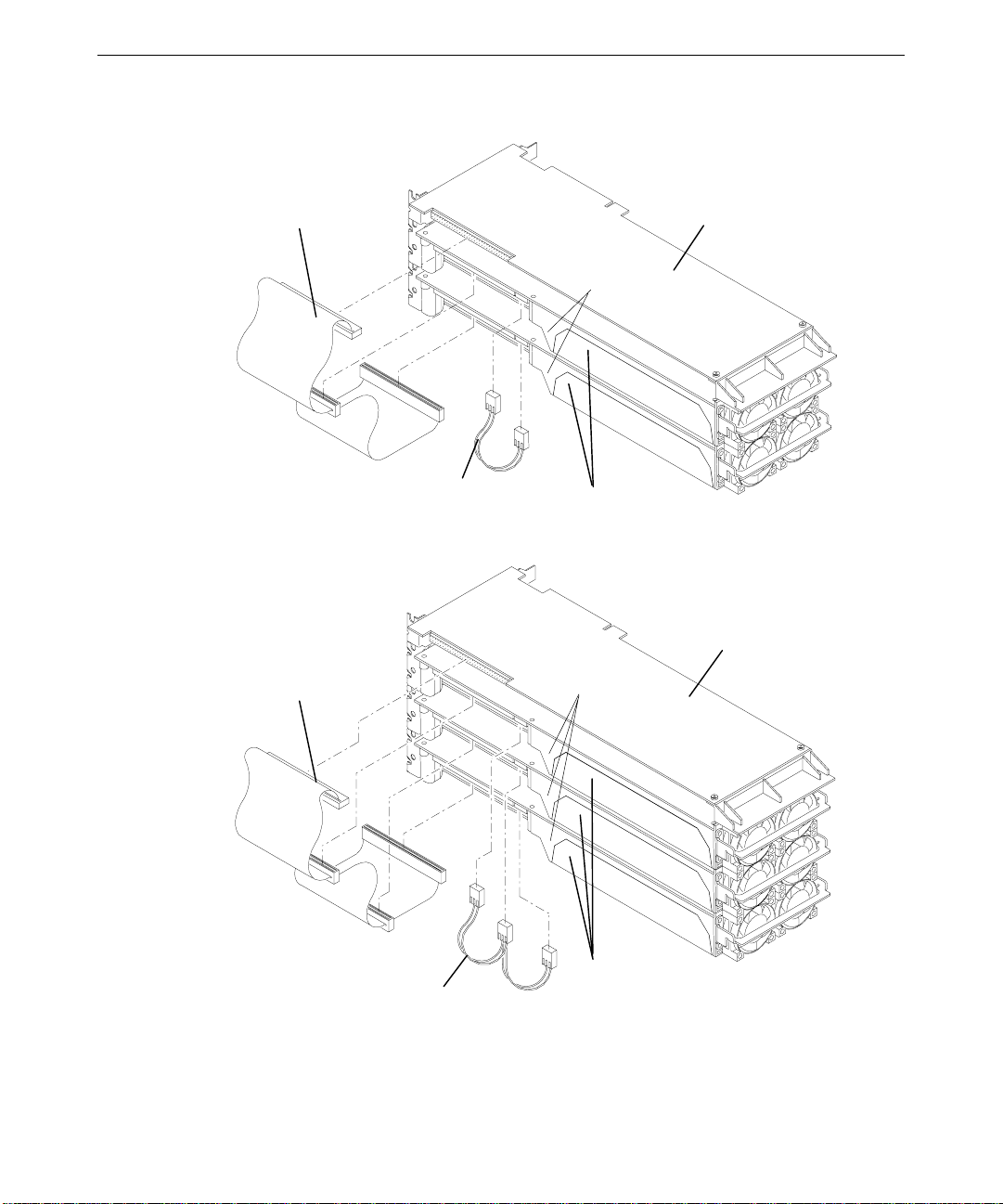
The following figure shows two RealiZm II cards.
11
Vertex
Data
Bus
Cable
Plastic Shrouds
Clock Sync Cable
The following figure shows three RealiZm II cards.
Vertex
Data
Bus
Cable
Plastic
Shrouds
Geometry
Accelerator
Card
RealiZm II
Cards
Geometry
Accelerator
Card
RealiZm II
Clock Sync Cable
Cards
5. Use a quarter-inch nutdriver to remove the screws that secure the card(s) to the system
chassis. Retain the screws.
Page 20

12
If you are installing a new Geometry Accelerator card, use a quarter-inch nutdriver to
remove the blanking plate from the slot into which you want to install the card. Retain the
screw.
6. Remove the installed card(s) from the system.
7. Install the new RealiZm II card(s) or Geometry Accelerator card in the slots from which
you removed the previously installed cards.
8. Install the screws that were previously removed to secure the RealiZm II or Geometry
Accelerator card(s) to the system chassis.
9. If you are installing or reinstalling a Geometry Accelerator card, connect the vertex data
bus cable between it and the RealiZm II card(s). Refer to the figure in step 4.
NOTE The connector of the vertex data bus cable can be installed in only one orientation.
10. If you are replacing RealiZm II cards in a multiple-screen configuration, connect the
clock sync cable between the RealiZm II cards. Refer to the figure in step 4.
CAUTION The clock sync cable installs only one way. Do not force the keyed connector. Ensure pin 1
of both cable connectors engages pin 1 on both card connectors. The black wire connects to
pin 4.
11. Close the system base unit.
12. Go to “Connecting Monitors to RealiZm II Cards” in Chapter 1 to connect the monitor
cables.
13. Restart the system and log on to the Windows NT operating system.
14. To recognize multiple screens, use Display in the Control Panel to configure the video
display driver. See “Configuring RealiZm II Video Display Properties” in Chapter 1 for
more information on video display properties.
Installing a Multiple-screen Upgrade
A multiple-screen upgrade provides components to upgrade your workstation from a singlescreen configuration to a dual- or triple-screen configuration. Verify that you have the
following items.
u
RealiZm II cards
u
Dual- or triple-screen vertex data bus cable (used only if optional Geometry Accelerator
is installed)
u
Dual- or triple-screen clock sync cable
u
Antistatic wrist strap
To install a multiple-screen upgrade, follow the instructions given in “Replacing RealiZm II
Cards or the Optional Geometry Accelerator Card.”
Page 21

Reinstalling the RealiZm II Video Display Driver
Follow these instructions if you need to reinstall the RealiZm II video display driver.
To reinstall the RealiZm II video display driver:
1. Turn on system power and log on to the Windows NT operating system.
2. From the Start menu, go to Settings/Control Panel/Display/Settings.
3. In the Settings tab, click Display Type.
4. In the Display Type dialog, click Change.
5. In the Change Display dialog, click Have Disk.
6. Insert the diskette containing the RealiZm II video display driver into the system’s floppy
disk drive; then click OK.
7. At Change Display, click OK.
8. At the third-party driver warning, click Yes.
9. At the Installing Driver dialog, click OK.
10. At the Display Type dialog, click Close.
13
11. If desired, configure the video display according to the system configuration and your
preferences. Refer to your system documentation, or select a setting and press
more information.
12. Click Apply at the bottom of the dialog to apply the changes.
13. Remove the diskette from the system’s floppy disk drive.
14. Restart the system.
Troubleshooting the Installation
If you suspect a hardware problem, use the following troubleshooting procedures to help
determine which hardware assembly to return for repair.
Diagnostics
Diagnostic utilities for checking the RealiZm II and Geometry Accelerator cards and
instructions for using them are available on the World Wide Web or from the Intergraph
Bulletin Board Service (IBBS). Refer to the Preface of this document for more information.
F1, for
Page 22

14
Video Display
The following table lists some common video configuration problems.
Problem
Display is black, not synchronized, or
distorted.
Monitor does not support a selected
resolution or refresh rate.
Two or three RealiZm II cards installed,
but you cannot select the Multiple Screen
option.
A dim line, rolling vertically, is visible on
the screen (for multiple screens only).
Action
Restart Windows NT in VGA mode.
Select a supported resolution and refresh rate.
Verify proper installation of all RealiZm II cards
(only one card was detected).
Verify proper installation of the clock sync
cable.
Obtaining a Usable Video Resolution
The system operates in VGA mode when the video display driver is not running to
accommodate all monitor types. VGA mode is used during initial installation of the video
display driver and when experiencing video problems. If you select a resolution that causes
the monitor to display incorrectly, do not press
operating system. Instead, use the Last Known Good option to return to the last known good
configuration recorded by Windows NT.
To use the Last Known Good option:
1. Restart the system.
2. Press the space bar at the following prompt:
Press space bar NOW to invoke the Last Known Good Menu
CTRL+ALT+DEL to log on to the Windows NT
If using the Last Known Good option fails to correct the video display problems, you can
obtain a functional video resolution by restarting the system in VGA mode.
Page 23

To restart the system in VGA mode:
1. Restart the system.
2. At the boot screen, select the VGA version of the operating system.
Determining a Defective Unit
If the monitor display is distorted, ensure the software setup is correct for the monitor type. If
the software setup is correct, use a similar type monitor (if available and functioning properly)
to determine if the workstation is defective.
To determine a defective unit:
1. Save and exit from all files, if possible; and then shut down Windows NT.
2. Turn off the power to the monitor and to the system base unit.
CAUTION Always turn off the power to the workstation before connecting or disconnecting the cables.
3. Check and reseat all card and cable connections as needed.
4. Turn on the monitor power. If the Power On LED does not illuminate, return the monitor.
5. Turn on the power to the system base unit. If the Power On LED on the base unit does
not illuminate, or if the BIOS beep codes indicate a failure, return the workstation.
15
Page 24

16
Page 25

3 Technical Information
The following technical information is subject to change without notice.
General Specifications
17
Max Screen
Graphics Card
ZX13 1.3 Mpixels 16 MB SDRAM
ZX13-T 1.3 Mpixels 16 MB SDRAM 4 - 64 MB SDRAM
ZX13-G 1.3 Mpixels 16 MB SDRAM
ZX13-GT 1.3 Mpixels 16 MB SDRAM 4 - 64 MB SDRAM
VX113-T 1.3 Mpixels 16 MB SDRAM 16 MB SDRAM
VX113-GT 1.3 Mpixels 16 MB SDRAM 16 MB SDRAM
VX113 AGP-T 1.3 Mpixels 16 MB SDRAM 16 MB SDRAM
VX113 AGP-GT 1.3 Mpixels 16 MB SDRAM 16 MB SDRAM
ZX25 2.5 Mpixels 32 MB SDRAM
ZX25-T 2.5 Mpixels 32 MB SDRAM 4 - 64 MB SDRAM
ZX25-G 2.5 Mpixels 32 MB SDRAM
ZX25-GT 2.5 Mpixels 32 MB SDRAM 4 - 64 MB SDRAM
VX25 2.5 Mpixels 32 MB SDRAM
VX25-T 2.5 Mpixels 32 MB SDRAM 4 - 64 MB SDRAM
VX25-G 2.5 Mpixels 32 MB SDRAM
VX25-GT 2.5 Mpixels 32 MB SDRAM 4 - 64 MB SDRAM
Resolution
Monitor Resolutions
RealiZm II cards support standard and Intergraph multi-sync monitors at the following
resolutions and maximum refresh rates (Hz).
Frame Buffer Texture Memory
Geometry
Acceleration
✔
✔
✔
✔
✔
✔
✔
✔
Resolution ZX13 VX113 VX113 AGP ZX25 VX25
640 x 480 85 85 85 85 85
800 x 600 85 85 85 85 85
1024 x 768 85 85 85 85 85
1152 x 864 85 85 85 85 85
1280 x 960 85 85 85 85 85
1280 x 1024 85 85 85 85 85
1600 x 1200 75 75
1824 x 1368 65 65
Page 26

18
RealiZm II cards support Intergraph’s high definition InterView 24-inch monitors at the
following resolutions and maximum refresh rates (Hz).
Resolution
640 x 480 60 60 60 60 60
1280 x 800 90 90 90 90 90
1280 x 1024 75 75 75 75 75
1440 x 900 85 85 85 90 90
1600 x 1024 76 76
1600 x 1200 75 75
1824 x 1128 75 75
1920 x 1080 72 72
1920 x 1200 70 70
RealiZm II cards support Intergraph’s high definition InterView 28-inch monitors at the
following resolutions and maximum refresh rates (Hz).
Resolution
640 x 480 75 75 75 75 75
800 x 600 75 75 75 75 75
856 x 480 75 75 75 75 75
1024 x 768 75 75 75 75 75
1280 x 720 75 75 75 75 75
1360 x 766 90 90 90 90 90
1520 x 856 85 85 85 90 90
1600 x 1200 70 70
1920 x 1080 75 75
2048 x 1152 72 72
ZX13 VX113 VX113 AGP ZX25 VX25
ZX13 VX113 VX113 AGP ZX25 VX25
Cooling System
RealiZm II cards include high-power components that require proper cooling to ensure proper
operation. On a ZX13, ZX25, or VX25 card, a duct covers the card and directs air over the
components from two fans mounted at one end of the card. Air from inside the assembly
moves outside the system at the I/O end of the card. On the VX113 and VX113 AGP cards,
heat sinks provide component cooling.
Page 27

Texture Memory
A ZX13, ZX25, or VX25 card provides texture memory by adding two dual inline memory
module (DIMM) sockets. Both DIMM sockets must be populated with the same density
DIMM. A slide-out cover provides easy access to the texture memory sockets. Although the
VX25 card supports 4 MB of texture memory, 16 MB or larger is recommended for maximum
performance.
The VX113 or VX113 AGP cards provide texture memory by including 16 MB of memory on
the card. No other texture memory options are available.
19
Texture
Memory
Bits Per Texel
(RGBA)
Total Texels
4 MB 32 1 MTexels
16 MB 32 4 MTexels
32 MB 32 8 MTexels
64 MB 32 16 MTexels
Geometry Accelerator Support
An optional Geometry Accelerator card provides lighting and transformation operations for
RealiZm II cards, to offload the system’s processors and provide for higher benchmark and
application performance.
u
The Geometry Accelerator card for VX113 and VX113 AGP uses twelve digital signal
processors (DSPs).
u
The Geometry Accelerator card for ZX13, VX25, and ZX25 uses six DSPs.
The Geometry Accelerator card sends data to the RealiZm II cards via a dedicated vertex data
bus, which has the following features:
u
Dedicated 60-pin ribbon cable interface
u
Peak transfer rate of 132 MB per second
u
Up to three RealiZm II cards can be interfaced to a single Geometry Accelerator card
Page 28

20
Interfaces
A ZX13, ZX25, or VX25 card has three interface connections: a stereo sync output port, a
video output port, and a VGA input port.
A VX113 or VX113 AGP graphics card has two interface connections: a stereo sync output
port and a video output port.
Stereo Sync Output Port
The stereo sync output port provides connection to the LCD shutter glasses’ emitter module.
The following table provides the pin connections for the stereo sync output port.
Signal Name
Ground 1
Ground 2
+12V 3
Stereo Sync 4
No Connect 5
The stereo port is female, 5-pin, mini-DIN as shown in the following figure.
5
3
Pin
4
2
1
Page 29

Video Output Port
The video output port provides connection to the monitor. The recommended cable length is
less than three meters. The following table provides the pin connections for the video output
port.
21
Signal Name
Pin
Red Analog Video 1
Green Analog Video 2
Blue Analog Video 3
Monitor ID [2] 4
Ground 5
Ground 6
Ground 7
Ground 8
Supply +5V 9
Ground 10
Monitor ID [0] 11
Monitor ID [1] or Bidirectional Data (SDA) for DDC 12
Horizontal/Composite Sync 13
Vertical Sync 14
Monitor ID [3] or Data Clock (SCL) for DDC 15
The video output port is female, 15-pin, D-Sub as shown in the following figure.
15
5
1
6
Page 30

22
VGA Input Port
The VGA input port allows connection of a VGA device to be used by the system while in
VGA graphics mode.
NOTE When the VGA input port is not used, an on-board VGA device assumes this function.
The following table provides the pin connections for the VGA input port.
Signal Name
Pin
Red Analog Video 1
Green Analog Video 2
Blue Analog Video 3
Monitor ID [2] 4
Cable Sense 5
Ground 6
Ground 7
Ground 8
No Connect 9
Ground 10
Monitor ID [0] 11
Monitor ID [1] or Bidirectional Data (SDA) for DDC 12
Horizontal/Composite Sync 13
Vertical Sync 14
Monitor ID [3] or Data Clock (SCL) for DDC 15
The VGA input port is female, 15-pin, D-Sub as shown in the following figure.
15
5
1
6
Page 31

Index
23
A
About this document, v
Antistatic precautions, 7
C
Changing the default video display
driver, 5
Clock sync cable
dual-screen connection, 11
triple-screen connection, 11
Configuring
RealiZm II video display
properties, 4
Connection
clock sync cable
dual-screen, 11
triple-screen, 11
monitor cables, 2
multi-screen, 3
single-screen, 3
vertex data bus cable
dual-screen, 11
single-screen, 10
triple-screen, 11
Cooling system, 18
Customer support, vi
D
Default video display driver,
changing, 5
Defective unit
determining, 15
Diagnostics, 13
Document
about, v
conventions, v
G
Geometry Accelerator
installing, 10
replacing, 7
support, 19
Getting started, 1
changing default video display
driver, 5
configuring RealiZm II video
display properties, 4
RealiZm II
cards, 1
configurations, 2
connecting monitors, 2
features and functions, 1
starting Windows NT, 3
H
Hardware support services, vi
I
Installing
Geometry Accelerator cards,
10
multiple-screen upgrade, 12
RealiZm II cards, 10
texture memory, 8
Interfaces, 20
stereo sync output port, 20
VGA input port, 22
video output port, 21
Intergraph Bulletin Board Service
(IBBS), vi
L
Last known good, 14
F
FAXLink, vii
M
Monitor
Page 32

24
cables, connecting, 2
resolutions, 17
Multiple-screen
monitor connection, 3
upgrade, installing, 12
O
Operating system information, v
P
Packing list
multiple-screen option,
verifying, 12
Pinouts
stereo sync output port, 20
VGA input port, 22
video output port, 21
Port
stereo sync output, 20
VGA input, 22
video output, 21
Powering on the system, 3
Precautions, 7
S
Selecting
last known good, 14
VGA mode, 15
Single-screen connection, 3
Software support services, vi
Specifications, 17
cooling system, 18
Geometry Accelerator support,
19
interfaces, 20
monitor resolutions, 17
InterView 24-inch, 18
InterView 28-inch, 18
multi-sync, 17
RealiZm II cards, 17
texture memory, 19
Stereo sync output port pinouts, 20
Support options, vii
Support services
hardware, vi
software, vi
telephone, vii
System, powering on, 3
R
RealiZm II
cards, 1
configurations, 2
configuring video display
properties, 4
connecting monitors, 2
features and functions, 1
graphics, upgrading, 7
reinstalling the video display
driver, 13
replacing, 7, 10
upgrading graphics, 7
Reinstalling
RealiZm II video display
driver, 13
Replacing
Geometry Accelerator card, 7,
10
RealiZm II cards, 7, 10
T
Telephone support services, vii
Texture memory, 19
installing, 8
socket, 8
Troubleshooting, 13
U
Upgrading
RealiZm II graphics, 7
Usable video resolution, 14
V
Vertex data bus cable
dual-screen connection, 11
single-screen connection, 10
triple-screen connection, 11
VGA
Page 33

25
input port pinouts, 22
mode, 15
Video
display
properties, 4
troubleshooting, 14
driver, reinstalling, 13
output port pinouts, 21
resolution, usable, 14
W
Windows NT, starting, 3
World Wide Web, vi
Page 34

26
Page 35

Returned Goods Authorization (RGA) Form
Date Returned Base Serial No.
(On white bar code ID plate on back of base unit)
RGA No.
From Customer Name
Customer Contact Phone
Mail Address
Reason for Return
(From Intergraph Customer Response Center)
NOTE All returned equipment MUST be shipped in original Intergraph packaging to obtain warranty
service.
WARNING Back up disk drives before returning equipment. Intergraph is not responsible for data
lost in shipping or repair process.
Page 36

Warranty Procedure
Some malfunctioning equipment cannot be repaired in the field, and you must return it to Intergraph for
repair. Follow these steps to obtain a Returned Goods Authorization (RGA) log number and return the
malfunctioning equipment.
1. Determine the serial number of the system. The serial number is located on the white bar code
identification label on the back of the base unit.
2. Call the Intergraph Customer Response Center at 1-800-633-7248, and identify your call to the
operator as a Warranty Call. After giving the operator the serial number of the system, you will be
assigned a RGA log number.
3. Complete the RGA Form on the previous page, entering the RGA log number obtained from the
Customer Response Center. Ensure that the address in the From section is the location to which you
want the equipment to be returned.
4. Place the RGA form in the box containing the equipment. This form must accompany returned
equipment.
5. Secure a Repair Depot address label from the next page to the box containing the equipment.
6. Ship the box containing the equipment to Intergraph.
When the service activity has been completed by Intergraph, the repaired or replaced equipment will be
shipped to the address listed on the RGA Form.
NOTE Parts damaged during shipping and parts not covered by the warranty are liable for repair
charges.
Page 37

TO Repair Depot RGA No. ________________________
Intergraph Corporation
9805 Kellner Road
Huntsville AL 35894
TO Repair Depot RGA No. ________________________
Intergraph Corporation
9805 Kellner Road
Huntsville AL 35894
TO Repair Depot RGA No. ________________________
Intergraph Corporation
9805 Kellner Road
Huntsville AL 35894
Page 38

 Loading...