

Page 1

RealiZm Graphics
Hardware User’s Guide
February 1997
DHA017120
Page 2

Warranties and Liabilities
The information and the software discussed in this document are subject to change without notice and
should not be considered commitments by Intergraph Corporation. Intergraph Corporation assumes no
responsibility for any errors in this document.
The software discussed in this document is furnished under a license and may be used or copied only in
accordance with the terms of the license. No responsibility is assumed by Intergraph for the use or
reliability of software on equipment that is not supplied by Intergraph or its affiliated companies.
All warranties given by Intergraph Corporation about equipment or software are set forth in your purchase
contract, and nothing stated in, or implied by, this document or its contents shall be considered or deemed a
modification or amendment of such warranties.
Copyright
1997, Intergraph Corporation including this documentation, and any software and its file formats and
audio-visual displays described herein; all rights reserved; may only be used pursuant to the applicable
software license agreement; contains confidential and proprietary information of Intergraph and/or other
third parties which is protected by copyright, trade secret and trademark law and may not be provided or
otherwise made available without prior written authorization.
Restricted Rights Legend
Use, duplication, or disclosure by the United States Government is subject to restrictions as set forth in
subdivision (c)(1)(ii) of the rights in technical data and computer software clause at DFARS 252.227-7013.
Unpublished rights reserved under the copyright laws of the United States.
Intergraph Corporation
Huntsville AL 35894-0001
Trademarks
Intergraph and the Intergraph logo are registered trademarks of Intergraph Corporation. RealiZm and
TDZ are trademarks of Intergraph Corporation.
Microsoft and Windows are registered trademarks of Microsoft Corporation. Windows NT is a
trademark of Microsoft Corporation.
Other brands and product names are trademarks of their respective owners.
Page 3

FCC Compliance
This equipment has been tested and found to comply with the limits for a Class A digital device, pursuant to
part 15 of the FCC Rules. These limits are designed to provide reasonable protection against harmful
interference when the equipment is operated in a commercial environment. This equipment generates, uses,
and can radiate radio frequency energy. If the equipment is not installed and used in accordance with the
instruction manual, it may cause harmful interference to radio communications.
Operation of this equipment in a residential area is likely to cause harmful interference in which case the
user will be required to correct the interference at his own expense.
DOC Compliance
This digital apparatus does not exceed the Class A limits for radio noise emissions from digital apparatus
set out in the Radio Interference Regulations of the Canadian Department of Communications.
Warnings
Changes or modifications made to the system that are not approved by the party responsible for compliance
could void the user’s authority to operate the equipment.
To reduce the risk of electrical shock, do not attempt to open the equipment unless instructed. Do not use a
tool for purposes other than instructed.
There are no user serviceable parts in the power supply. Refer all servicing of the power supply to qualified
service personnel.
There is a danger of explosion if the battery is incorrectly replaced. Replace the battery only with the same
or equivalent type as recommended by the manufacturer. Dispose of used batteries according to the
manufacturer’s instructions.
Cautions
THIS PRODUCT CONFORMS TO THE APPLICABLE REQUIREMENTS OF 21 CFR SUBCHAPTER
J AT DATE OF MANUFACTURE.
Read all safety and operating instructions before using the equipment. Keep these instructions for future
reference. Follow all warnings on the equipment or in the operating instructions.
Page 4

Page 5

Contents
Preface......................................................................................................................................ix
About This Document...............................................................................................................ix
Document Conventions..............................................................................................................x
Finding Operating System Information......................................................................................x
Getting Documentation and Training.........................................................................................x
Getting Telephone Support .......................................................................................................xi
Using the Intergraph Bulletin Board Service ............................................................................xi
Using the Intergraph FAXLink................................................................................................ xii
Finding Intergraph on the Internet........................................................................................... xii
1 Getting Started.....................................................................................................................1
RealiZm Graphics Accelerators .................................................................................................1
RealiZm Features and Functions................................................................................................1
RealiZm Configurations.............................................................................................................2
Starting Windows NT.................................................................................................................3
RenderGL Run-Time Library.....................................................................................................3
Configuring Display Properties..................................................................................................4
Changing the Default Video Display Driver..............................................................................6
v
2 Upgrading or Replacing Z10...............................................................................................7
Precautions.................................................................................................................................7
Installing a Texturing Accelerator..............................................................................................8
Replacing Z10 or Z10-T...........................................................................................................10
Installing a Dual-Screen Upgrade ............................................................................................12
Connecting the Video Cables...................................................................................................15
Installing the Video Display Driver..........................................................................................17
Troubleshooting .......................................................................................................................18
Diagnostics.................................................................................................................18
Video Display............................................................................................................18
Obtaining a Usable Video Resolution........................................................................19
Determining a Defective Unit....................................................................................19
3 Upgrading or Replacing Z13, Z25, and V25 ...................................................................21
Precautions...............................................................................................................................21
Installing Texture Memory.......................................................................................................22
Replacing Z13, Z25, V25, or Geometry Accelerator ...............................................................24
Installing a Dual-Screen Upgrade ............................................................................................26
Connecting the Video Cables...................................................................................................28
Installing the Video Display Driver..........................................................................................30
Page 6

vi
Troubleshooting.......................................................................................................................31
Diagnostics................................................................................................................ 31
Video Display............................................................................................................ 31
Obtaining a Usable Video Resolution....................................................................... 31
Determining a Defective Unit....................................................................................32
4 Technical Description........................................................................................................33
Rasterization Accelerator Features..........................................................................................33
PCI Bus Interface...................................................................................................... 34
Graphics Engine........................................................................................................ 35
Texture Processor...................................................................................................... 36
Frame Buffer............................................................................................................. 37
Rasterization Accelerator Functions........................................................................................ 40
Pixelization Accelerator............................................................................................ 41
Texture Processor...................................................................................................... 42
Frame Buffer............................................................................................................. 42
Geometry Accelerator Features and Functions........................................................................ 45
High-Speed Graphics DMA Engine.......................................................................... 45
MIMD DSP Architecture .......................................................................................... 45
Sequence Controller..................................................................................................45
5 Hardware Description....................................................................................................... 47
Rasterization Accelerator Components.................................................................................... 47
Z10............................................................................................................................ 47
Z13............................................................................................................................48
Z25 and V25.............................................................................................................. 49
PCIDMA...................................................................................................................50
Graphics Engine and Texture Processor.................................................................... 50
Z10 Texturing Accelerator........................................................................................52
Texture Memory........................................................................................................ 53
Resolver Architecture................................................................................................ 53
Video Memory.......................................................................................................... 54
Video Selector and Mapper (Z10 Only).................................................................... 54
Digital-to-Analog Converter ..................................................................................... 54
Geometry Accelerator Components......................................................................................... 55
PCIDMA...................................................................................................................55
I/O FIFO.................................................................................................................... 55
DSPs.......................................................................................................................... 56
Sequence Controller..................................................................................................56
6 Specifications ..................................................................................................................... 57
Cooling System (Z25 and V25)............................................................................................... 57
Texturing System..................................................................................................................... 58
Geometry Accelerator Support................................................................................................ 58
Monitor Resolutions................................................................................................................ 59
Page 7

vii
Interfaces..................................................................................................................................60
Video Output Port......................................................................................................60
VGA Input Port..........................................................................................................61
Stereo Sync Output Port.............................................................................................62
Index........................................................................................................................................63
Returned Goods Authorization (RGA) Form
Warranty Procedure
Repair Depot Address Labels
Page 8

viii
Page 9

Preface
The RealiZm Graphics Hardware User’s Guide provides instructions for installing
Intergraph’s Z10, Z13, Z25, and V25 three-dimensional (3D) graphics accelerators into
Intergraph’s 3D graphics workstations. This guide provides hardware and software
installation procedures, troubleshooting information, technical and hardware descriptions, and
specifications.
About This Document
The RealiZm Graphics Hardware User’s Guide is organized as follows:
u
Chapter 1, “Getting Started,” introduces RealiZm graphics accelerators.
u
Chapter 2, “Installing or Replacing Z10,” provides static precautions and instructions for
installing the optional texturing accelerator onto the Z10 board. It provides replacement
instructions for Z10 (and Z10-T) and installing Z10 (or Z10-T) for dual-screen use in a
deskside system. It also provides instructions for installing the video display driver and
troubleshooting.
ix
u
Chapter 3, “Installing or Replacing Z13, Z25, and V25,” provides static precautions and
instructions for installing optional texture memory on Z13, Z25, and V25. It provides
replacement instructions for the Z13, Z25, V25, or optional Geometry Accelerator and
installing Z13 (or Z25, or V25) for dual-screen use in a deskside system. It also provides
instructions for installing the video display driver and troubleshooting.
u
Chapter 4, “Technical Description,” covers the technical features and functions of the
RealiZm graphics accelerators.
u
Chapter 5, “Hardware Description,” contains a hardware description of the RealiZm
graphics accelerators.
u
Chapter 6, “Specifications,” lists the specifications for the RealiZm graphics accelerators.
Page 10

x
Document Conventions
Bold Commands, words, or characters that you key in literally.
Italic Variable values that you supply, or cross-references.
Monospace Output displayed on the screen.
SMALL CAPS Key names on the keyboard, such as D, ALT or F3; names of files and
directories. You can type filenames and directory names in the dialog boxes
or the command line in lowercase unless directed otherwise.
CTRL+D Press a key while simultaneously pressing another key; for example, press
CTRL and D simultaneously.
ALT,SHIFT,F Press keys sequentially; for example, press ALT, then press SHIFT, then press
F.
Finding Operating System Information
For more detailed information on the Windows NT Workstation 4.0 operating system, refer to
the printed and online Windows NT documentation from Microsoft:
u
For basic information on using and installing Windows NT Workstation 4.0, refer to Start
Here, delivered in the Windows NT Workstation software package.
u
For detailed information on using Windows NT Workstation 4.0, refer to Windows NT
Workstation Help.
Getting Documentation and Training
You can purchase additional product documentation from Intergraph.
u
In the United States, contact your sales account representative, call the Intergraph Order
Desk at 1-800-543-1054, or send a fax to 1-800-548-3318 to place an order. If you call
or fax the Order Desk, have the document numbers ready for the items you wish to
purchase.
u
Outside the United States, contact the Intergraph subsidiary or distributor from which you
purchased your Intergraph product to place an order.
To find information on training for Intergraph products, or to enroll for an available class,
contact Intergraph Training Solutions at 1-800-240-3000.
Page 11

Getting Telephone Support
If you experience problems with your Intergraph product, or have questions about the
information in this document, you can contact Intergraph for help.
u
In the United States, call the Customer Response Center at 1-800-633-7248 between the
hours of 7:00 a.m. and 7:00 p.m. Central Time, Monday through Friday (except
holidays).
u
Outside the United States, contact the Intergraph subsidiary or distributor from which you
purchased your Intergraph product.
Have the following information readily available when you call:
u
The product’s serial number or your service/CPIN number.
u
The product’s name or model number.
u
Your name and telephone number.
u
A brief description of the question or problem.
xi
Using the Intergraph Bulletin Board Service
Available 24 hours a day, 7 days a week, the Intergraph Bulletin Board Service (IBBS) is an
electronic forum for Intergraph customers to exchange information with Intergraph's technical
and marketing staff, and with other Intergraph customers. You can use the IBBS to get
technical support information, documentation and training information, programs, and
software updates and fixes. The IBBS is also available for you to give suggestions, make
inquiries, and report problems.
To connect to the IBBS:
1. Set your system’s communications protocol for eight (8) data bits, no parity, one (1) stop
bit, and any baud rate up to 14,400.
2. Using a modem, dial the IBBS number, 1-205-730-8786. You can dial 1-205-730-6504 if
you are using a 2,400 baud connection.
Mirror sites are maintained for locations outside the United States. Information on these
sites is available on Intergraph Online, Intergraph’s World Wide Web server.
3. When connected, respond to the login request by keying in your user ID. If you have not
connected before, key in new to create a user ID.
Page 12

xii
4. Follow the menus to find what you need. If you are new to computer bulletin boards, the
IBBS provides clear choices and plenty of online help. A text file that explains IBBS
commands and organization is available for you to download.
If you have trouble connecting to or using the IBBS, log a support request through the
Customer Response Center (product entry IBBS), send a fax to 1-205-730-1110, or leave a
message for the System Operator (Sysop) at 1-205-730-1413.
Using the Intergraph FAXLink
You can use the Intergraph FAXLink to get technical support information by fax 24 hours a
day, 7 days a week. From a touch-tone phone or fax machine phone:
u
Call 1-800-240-4300 to get new user instructions, an index listing of available documents,
and an overview of the categories of available information.
u
Call 1-205-730-9000 to order the documents (up to 5 per call).
Finding Intergraph on the Internet
You can find Intergraph on the Internet in the following ways:
u
If you have a World Wide Web browser, connect to Intergraph Online, Intergraph’s
World WideWeb server, at http://www.intergraph.com. From the home page, follow
the links to Customer Services for information on available customer services and support
options.
u
If you have a File Transfer Protocol (FTP) program, connect to Intergraph at
ftp.intergraph.com.
u
If you have a Gopher program, connect to Intergraph at gopher.intergraph.com.
u
You can get information from Intergraph’s email server at info@intergraph.com. Put
help in the body of the message (the subject line is ignored) to get information on such
subjects as Intergraph’s online services and where to get World Wide Web browsers.
Page 13
1 Getting Started
This chapter introduces Intergraph’s RealiZm graphics accelerators, and provides information
on getting started using an Intergraph 3D graphics workstation equipped with a RealiZm
graphics accelerator.
RealiZm Graphics Accelerators
RealiZm Z10, Z13, Z25, and V25 are high-performance, OpenGL-based, 3D graphics
accelerators that include rasterization, optional texturing, and (for Z13, Z25, and V25)
optional geometry acceleration:
u
Z10 includes 12 MB of frame buffer memory and supports resolutions up to 1 Mpixels
(1152 x 864).
u
Z13 includes 16 MB of frame buffer memory and supports resolutions up to 1.3 Mpixels
(1280 x 1024).
1
u
Z25 includes 32 MB of frame buffer memory and supports resolutions up to 2.5 Mpixels
(1824 x 1368).
u
V25 includes 32 MB of frame buffer memory and supports resolutions up to 2.5 Mpixels
(1824 x 1368). Texture processing is 20 percent faster than Z25.
RealiZm Features and Functions
RealiZm graphics accelerators are used in Intergraph’s TDZ workstations. These graphics
accelerators offer many advanced features and functions, including the following:
u
Hardware support of Windows NT graphics (both GDI and OpenGL graphics operations)
u
Gouraud shading support and antialiased vector support
u
12 MB (Z10), 16 MB (Z13), or 32 MB (Z25 and V25) of frame buffer memory
u
Industry-standard Peripheral Component Interconnect (PCI) bus interface with high-speed
direct memory access (DMA) engine
u
84 video planes (Z10) or 90 video planes (Z10-T)
u
128 video planes (Z13, Z25, and V25)
u
Support of industry standard multi-sync monitors
Page 14

2
u
Optional hardware texture processing support with 8 MB of texture memory (Z10-T)
u
Optional hardware texture processing support with 4 MB, 16 MB,
32 MB, or 64 MB of texture memory (Z13 and Z25)
u
Optional hardware texture processing support with 16 MB,
32 MB, or 64 MB of texture memory (V25)
u
Optional geometry acceleration for lighting and transformation operations (Z13, Z25, and
V25)
Refer to Chapter 4, “Technical Description,” for a full description of the features and
functions of RealiZm graphics accelerators.
RealiZm Configurations
RealiZm graphics configurations are designated by the maximum resolution supported, and by
support for texture memory and geometry acceleration:
u
The number denotes the maximum supported resolution. For example, Z25 and V25
indicates support for a maximum resolution of 2.5 Mpixels.
u
The -T suffix denotes support for texture processing.
u
The -G suffix denotes support for geometry acceleration. Geometry acceleration is
optional for Z13, Z25, and V25, and is not available for Z10.
The available RealiZm graphics configurations are as follows:
Designation
Configuration
Z10 1.0 Mpixels
Z10-T 1.0 Mpixels, texture processing
Z13 1.3 Mpixels
Z13-T 1.3 Mpixels, texture processing
Z13-G 1.3 Mpixels, geometry acceleration
Z13-GT 1.3 Mpixels, geometry acceleration, texture processing
Z25, V25 2.5 Mpixels
Z25-T, V25-T 2.5 Mpixels, texture processing
Z25-G, V25-G 2.5 Mpixels, geometry acceleration
Z25-GT, V25-GT 2.5 Mpixels, geometry acceleration, texture processing
Page 15

Starting Windows NT
After setting up a system equipped with RealiZm graphics, you can power on the system and
start the Windows NT operating system.
CAUTION Verify that your 3D graphics system is properly set up and ready for use. For Z10, ensure that
the VGA loopback cable is connected as described in Chapter 2, “Upgrading or Replacing
Z10.”
To start Windows NT:
1. Turn on power to the monitor and to the system base unit.
2. At the boot screen, select the following option:
Windows NT Workstation Version 4.00
3
3. When prompted, press
CTRL+ALT+DEL.
4. Log on to Windows NT. Refer to the Windows NT documentation for instructions, if
necessary.
RenderGL Run-Time Library
Intergraph’s RenderGL run-time library is delivered with your TDZ workstation. This library
is delivered as a Dynamic Link Library (DLL) file. If you run an application that requires or
uses the RenderGL run-time library, you need to install the RenderGL DLL to your system.
The RenderGL DLL is delivered as follows:
u
Your system may have been delivered with a diskette containing the RenderGL DLL. If
so, refer to the
u
If your system was not delivered with a diskette containing the RenderGL DLL, you can
use the InterSite Version Manager to create the diskette. Run Version Manager from the
Welcome dialog that displays after you set up your TDZ workstation. After you create
the diskette, refer to the
For more information on the RenderGL run-time library, contact Intergraph’s Digital Media
Division. For more information on the Welcome dialog and Version Manager, refer to your
system’s hardware documentation and to Version Manager Help.
README.TXT file on the diskette for installation instructions.
README.TXT file on the diskette for installation instructions.
Page 16
4
Configuring Display Properties
To enable your system to use its installed graphics board, you must configure the video
display driver to use the RealiZm graphics accelerator. Intergraph installs the video display
driver on the system’s hard disk drive. The Display Properties dialog is available from the
Windows NT Control Panel to determine the system configuration and installed options.
Display Properties allows you to modify the video settings to meet your needs.
To start the Display Properties dialog:
1. At the screen’s bottom left corner, click Start.
2. Under Settings, open the Windows NT Control Panel.
3. In the Control Panel, open Display. The Display Properties dialog displays.
4. Select the Hardware Settings tab. The Hardware Setting page displays.
When a supported video display driver is running on your system, the Hardware Settings
page displays text describing the graphics hardware and monitor present on your system.
The page allows you to review and change the settings of your system’s video attributes,
such as monitor type, orientation, and other attributes.
NOTE If this is your first time to install the video display driver (for example, when re-installing
Windows NT), the Hardware Settings and Color Calibration pages do not display until you
restart the system.
Page 17
5. Select and change the supported settings as desired. Refer to Help for information about
each setting. Context-sensitive help is available by selecting a setting and pressing
F1.
6. Select the Color Calibration tab to change the gamma correction for your monitor, if
desired. The Color Calibration page displays.
5
NOTE The Color Calibration page is available only when the driver is running.
The appearance of the Color Calibration page varys, depending on your graphics
hardware and selected video display settings. If your system is configured with dual
screens, for example, the page displays two monitor icons to indicate a dual-screen
desktop. It can also indicate the dual screens in horizontal orientation or vertical
orientation (monitors stacked one on top of the other).
7. Select OK to apply the selected video attributes and to close the Display Properties
dialog, or select Cancel to close Display Properties without applying the video attributes.
8. If you have changed video attribute settings other than gamma correction, restart the
system for the changes to take effect.
Page 18

6
Changing the Default Video Display Driver
Once you have configured the video display as desired, change the default display driver so
that the video display driver runs automatically when you start the system.
To change the default video display driver:
1. Open System in the Windows NT Control Panel. The System dialog displays.
2. Under Operating System, select Windows NT Workstation Version 4.00 from
the displayed list.
NOTE Do not select the “VGA mode” version of the operating system. The system operates in VGA
mode when the video display driver is not running to accommodate all monitor types.
3. Select OK; then close Control Panel. The system will now use the video display driver by
default.
Page 19

2 Upgrading or Replacing Z10
This chapter describes upgrading or replacing a RealiZm Z10 graphics accelerator in a TDZ
workstation. It provides instructions for the following:
u
Installing an optional Texturing Accelerator on Z10
u
Replacing Z10 or Z10-T
u
Installing a Z10 or Z10-T dual-screen upgrade
u
Connecting the video cables
u
Installing the video display driver
u
Troubleshooting the installation
Refer to your system’s hardware documentation for detailed information on opening and
closing the system, avoiding electrostatic discharge, and installing and replacing option
boards.
7
If an item is missing or damaged, notify the Intergraph Customer Response Center at
1-800-633-7248 immediately.
Precautions
Static electricity can damage the components inside the system base unit, and can damage the
graphics accelerator boards. To minimize the possibility of electrostatic discharge, do the
following:
u
Do not remove a graphics accelerator board from its antistatic bag until you are ready to
install it.
u
Handle a graphics accelerator board as little as possible and by the edges only. Do not
drop a graphics accelerator board, and do not expose it to extremes of temperature or
moisture.
u
Use an antistatic wrist strap when handling a graphics accelerator board. There is no
increased risk of electrical shock when using the wrist strap. If the wrist strap does not
snugly contact bare skin, static protection will not be effective.
Page 20

8
To use an antistatic wrist strap:
1. Remove the antistatic wrist strap from its envelope. Unfold the wrist strap and wrap the
exposed adhesive side firmly around your bare wrist.
2. Peel the liner from the wrist strap copper foil; then attach the adhesive side of the copper
foil to a bare metal surface (electrical ground) inside the system base unit.
Installing a Texturing Accelerator
This section describes installing an optional texturing accelerator on a Z10 board. Adding a
texturing accelerator creates a Z10-T graphics accelerator with 8 MB of texture memory.
NOTE You must remove the Z10 board from the system to install a texturing accelerator.
To install a texturing accelerator to a Z10 board:
1. Shut down the system and turn off system power.
2. Disconnect the cables from the Video and VGA ports on the back of the system base unit.
3. Open the system base unit as required to gain access to the PCI option board slots. Slots
are identified in “Connecting the Video Cables” later in this chapter.
4. Use a quarter-inch nutdriver to remove the screws that secure the Z10 board to the system
chassis. Retain the screws.
5. Remove the Z10 board from the system.
NOTE The new Z10-T board set requires two adjacent PCI slots.
6. Use a quarter-inch nutdriver to remove the blanking plates from the following PCI slots:
Z10 board, desktop system: PCI slot 3
Z10 board, deskside system: PCI slot 4
Retain the screws.
7. Remove the texturing accelerator from the antistatic bag.
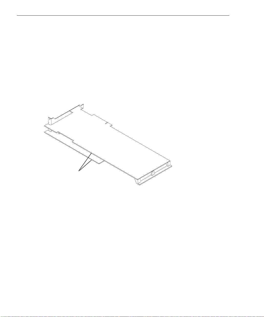
8. Using a Philips screwdriver, remove the two screws from the Texturing Accelerator I/O
panel shown in the following figure.
9. Align the texturing accelerator with the Z10 board. Insert the two captive screws of the
texturing accelerator with the standoffs on the Z10 board and tighten the screws. Refer to
the following figure.
CAUTION When tightening the captive screws, alternate between the screws using two turns each.
Page 21
Remove these two screws
from the Texturing Accelerator
I/O Panel before assembly.
9
Texturing Accelerator
I/O Panel
Texturing
Accelerator
Board
Captive Screws
(alternate tightening)
Z10 Board
10. Insert the two screws previously removed to secure the two I/O panels together.
11. Install the new Z10-T board set in the open PCI slot and in the slot from which you
removed the previously installed Z10 board.
12. Install the screws that were previously removed to secure the Z10-T board set to the
system chassis.
13. Close the system base unit.
14. Go to “Connecting the Video Cables” later in this chapter to connect the monitor and
VGA loopback cables.
15. Restart the system and log on to the Windows NT operating system.
16. Open Display in the Windows NT Control Panel. The Hardware Settings page of the
Display Properties dialog should display GLZ1-T or Z10-T next to Graphics Type. If
not, shut down and power off the system. Ensure that the texturing accelerator is properly
connected to the Z10 board.
Page 22
10
Replacing Z10 or Z10-T
This section describes replacing a Z10 board or a Z10-T board set in a desktop or
deskside TDZ workstation. The procedure also describes replacing a Z10 board with a Z10-T
board set.
NOTE In a desktop system, you cannot replace two Z10 boards with two Z10-T board sets, or install
two Z10-T board sets.
A Z10-T board set consists of two boards joined together as one unit. An installed Z10-T
board set requires two adjacent PCI slots. The following figure shows a Z10-T board set.
Z10-T Board Set
To replace Z10 or Z10-T:
1. Shut down the system and turn off system power.
2. Disconnect the cables from the Video and VGA ports on the back of the system base unit.
3. Open the system base unit as required to gain access to the PCI option board slots. Slots
are identified in “Connecting the Video Cables” later in this chapter.
Page 23
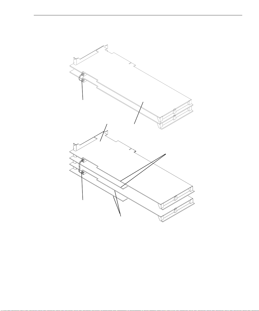
4. If replacing Z10 in a dual-screen configuration, remove the clock sync cable from
oard Set
between the Z10 boards or the Z10-T board sets. Refer to the following figures.
Clock Sync
Cable
Z10 Boards
Primary
Z10-T
Board Set
11
Clock Sync
Cable
Secondary
Z10-T
B
5. Use a quarter-inch nutdriver to remove the screws that secure the Z10 board or Z10-T
board set to the system chassis. Retain the screws.
6. Remove the Z10 board or Z10-T board set from the system.
7. If replacing a single Z10 board with a Z10-T board set in a desktop system, use a quarterinch nutdriver to remove the blanking plate from PCI slot 3. Retain the screw.
If replacing two Z10 boards with Z10-T board sets in a deskside system, use a quarter-
inch nutdriver to remove the blanking plates from PCI slots 4 and 5. Retain the screws.
Page 24

12
8. Install the new Z10 board or Z10-T board set in the slots from which you removed the
previously installed Z10 board or Z10-T board set.
If replacing a single Z10 board with a Z10-T board set, install the new Z10-T board set in
PCI slots 2 and 3.
If replacing two Z10 boards with Z10-T board sets in a deskside system, install one new
Z10-T board set in PCI slots 2 and 3, and the other in PCI slots 4 and 5.
9. If replacing Z10 in a dual-screen configuration, install the clock sync cable between the
Z10 boards or Z10-T board sets. Refer to the figures in step 4.
CAUTION The clock sync cable installs only one way. Do not force the keyed connector. Ensure pin 1
of both cable connectors engages pin 1 on both board connectors. The black wire connects
to pin 1.
10. Install the screws that were previously removed to secure the Z10 board or Z10-T board
set to the system chassis.
11. Close the system base unit.
12. Go to “Connecting the Video Cables” later in this chapter to connect the monitor and
VGA loopback cables.
Installing a Dual-Screen Upgrade
A dual-screen upgrade provides components to upgrade a TDZ workstation from a singlescreen configuration to a dual-screen configuration. Verify that you have the following items.
u
Z10 board or Z10-T board set
u
Diskette containing Intergraph video display driver software
u
Clock sync cable
u
Antistatic wrist strap
NOTE You cannot install a Z10-T dual-screen upgrade in a desktop system.
If an item is missing or damaged, notify the Intergraph Customer Response Center at
1-800-633-7248 immediately.
Page 25

13
To install a dual-screen upgrade:
1. Shut down the system and turn off system power.
2. Disconnect the cables from the Video and VGA ports on the back of the system base unit.
3. Open the system base unit as required to gain access to the PCI option board slots. Slots
are identified in “Connecting the Video Cables” later in this chapter.
4. Use a quarter-inch nutdriver to remove the blanking plates from the following PCI slots:
Z10 board, desktop system: PCI slot 2
Z10 board, deskside system: PCI slot 3
Z10-T board set, deskside system: PCI slots 4 and 5
Retain the screws.
5. Install the new Z10 board or Z10-T board set in the PCI slots opened in the previous step.
In a dual-screen configuration, the primary and secondary graphics accelerators are
determined as follows:
Z10 boards, desktop system: Primary in slot 1; secondary in slot 2
Z10 boards, deskside system: Primary in slot 2, secondary in slot 3
Z10-T board sets, deskside system: Primary in slots 2 and 3; secondary in slots 4
and 5
6. Install the screws that were previously removed to secure the Z10 board or Z10-T board
set to the system chassis.
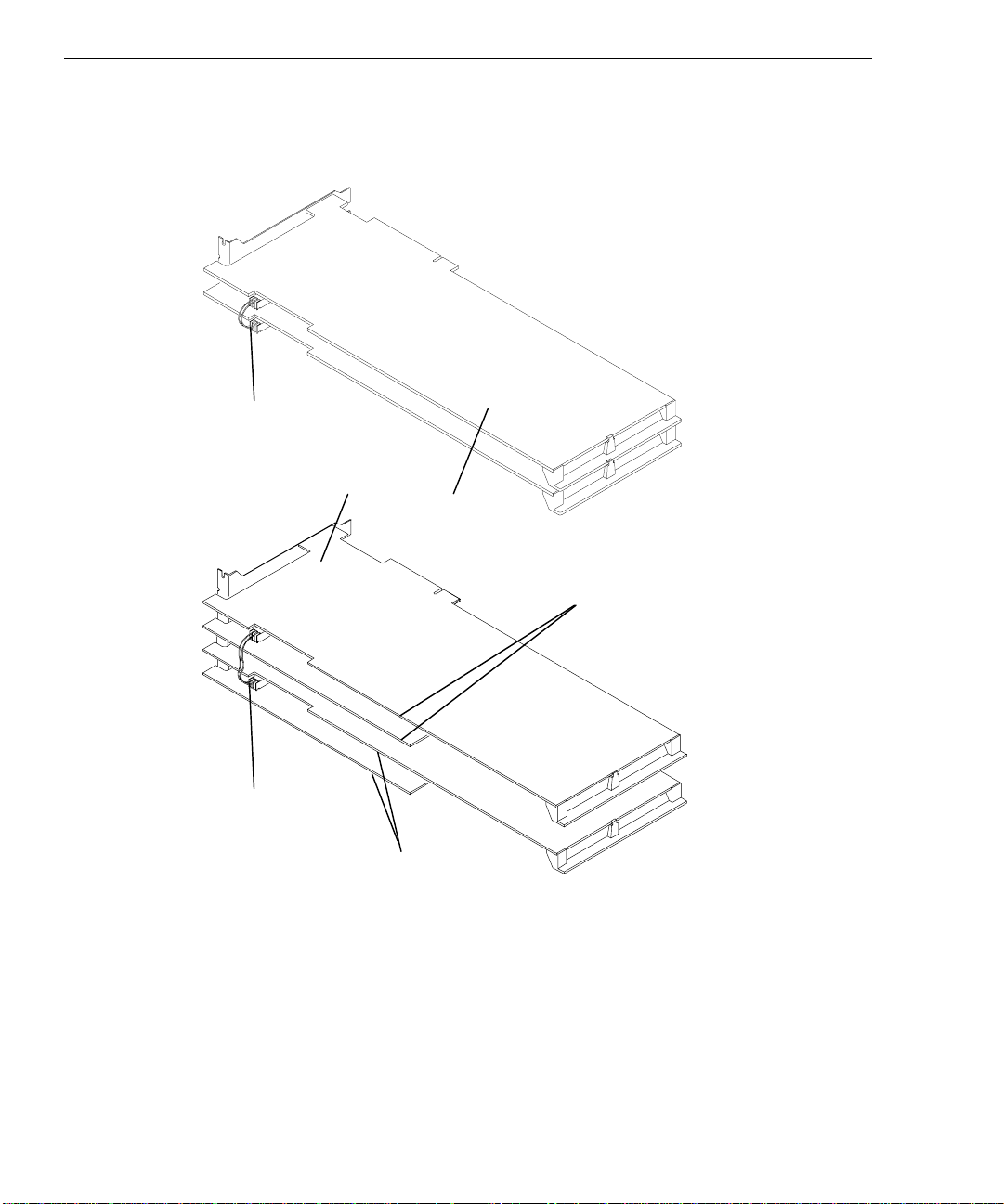
7. Install the clock sync cable between the Z10 boards or Z10-T board sets, as shown in the
following figures.
Page 26
14
Board Set
oard Set
CAUTION The clock sync cable installs only one way. Do not force the keyed connector. Ensure pin 1
of both cable connectors engages pin 1 on both board connectors. The black wire connects
to pin 1.
Clock Sync
Cable
Z10 Boards
Primary
Z10-T
Clock Sync
Cable
Secondary
Z10-T
B
8. Close the system base unit.
9. Go to “Connecting the Video Cables” later in this chapter to connect the monitor and
VGA loopback cables.
10. Restart the system and log on to the Windows NT operating system.
11. Use Display in the Windows NT Control Panel to configure the video display driver to
recognize dual screens. Refer to Chapter 1 for more information.
Page 27
Connecting the Video Cables
(
y)
(
y)
After replacing Z10 or Z10-T or installing a dual-screen upgrade in a TDZ workstation, use
the following instructions to connect the monitor cables and VGA loopback cables as
required.
CAUTION Do not connect a monitor cable to the VGA loopback cable ports. If you do, the system will
boot to a blue screen and stop, or the video will not display.
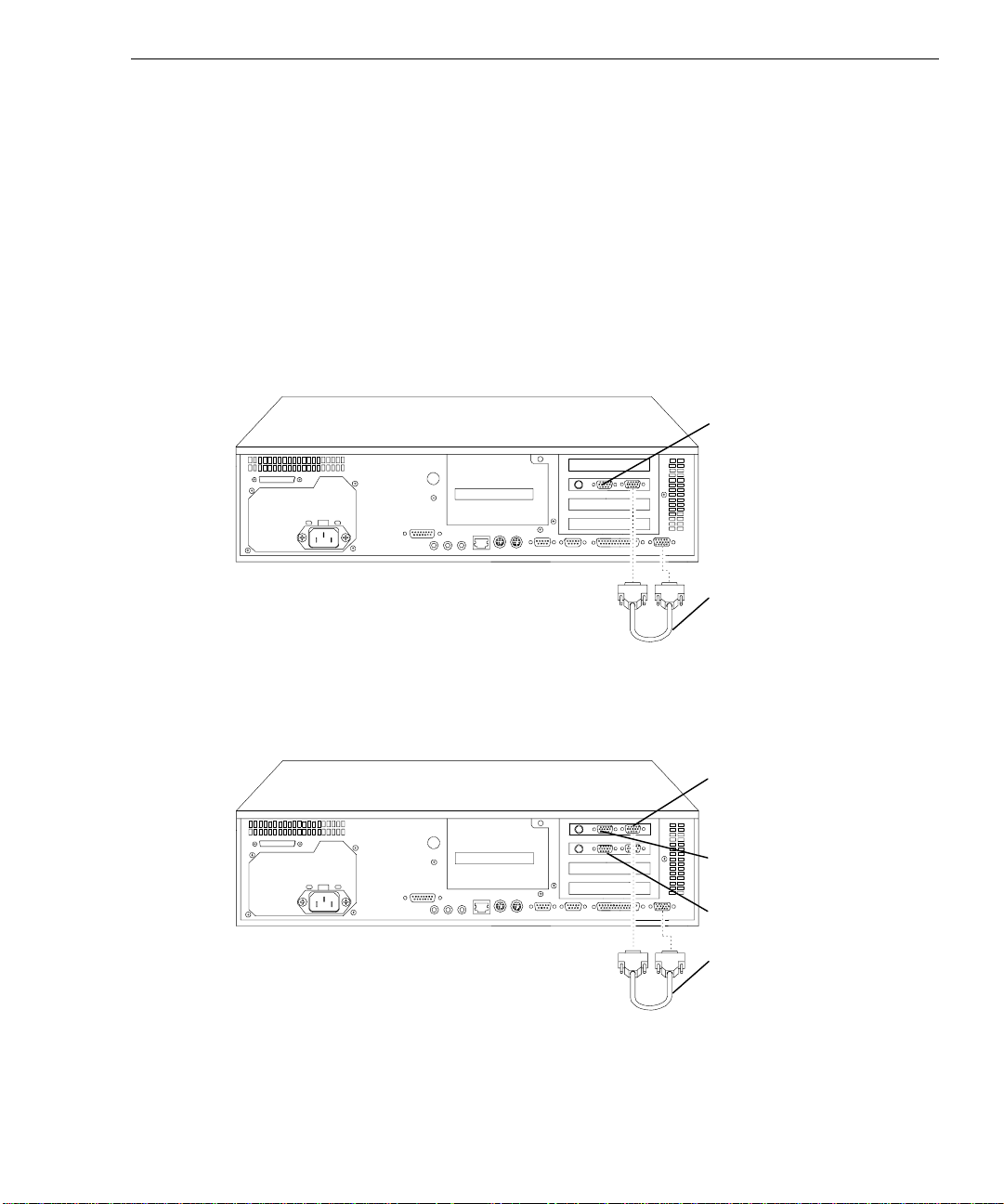
Single-screen Z10 or Z10-T in a desktop system: Connect the monitor cable to the Video
port, and connect the VGA loopback cable as shown in the following figure.
Video Port PCI Slot 2
15
VGA Loopback Cable
Dual-screen Z10 in a desktop system: Connect the monitor cables from the primary monitor
and the secondary monitor to the Video ports shown in the following figure. Connect the
VGA loopback cable as shown in the following figure.
VGA Port (Primary)
Video Port PCI Slot 1
Primar
Video Port PCI Slot 2
Secondar
VGA Loopback Cable
Page 28

16
(
y)
(
y)
Single-screen Z10 or Z10-T in a deskside system: Connect the monitor cable to the Video
port, and connect the VGA loopback cable as shown in the following figure.
VGA
Loopback
Cable
Video Port PCI Slot 2
VGA Port
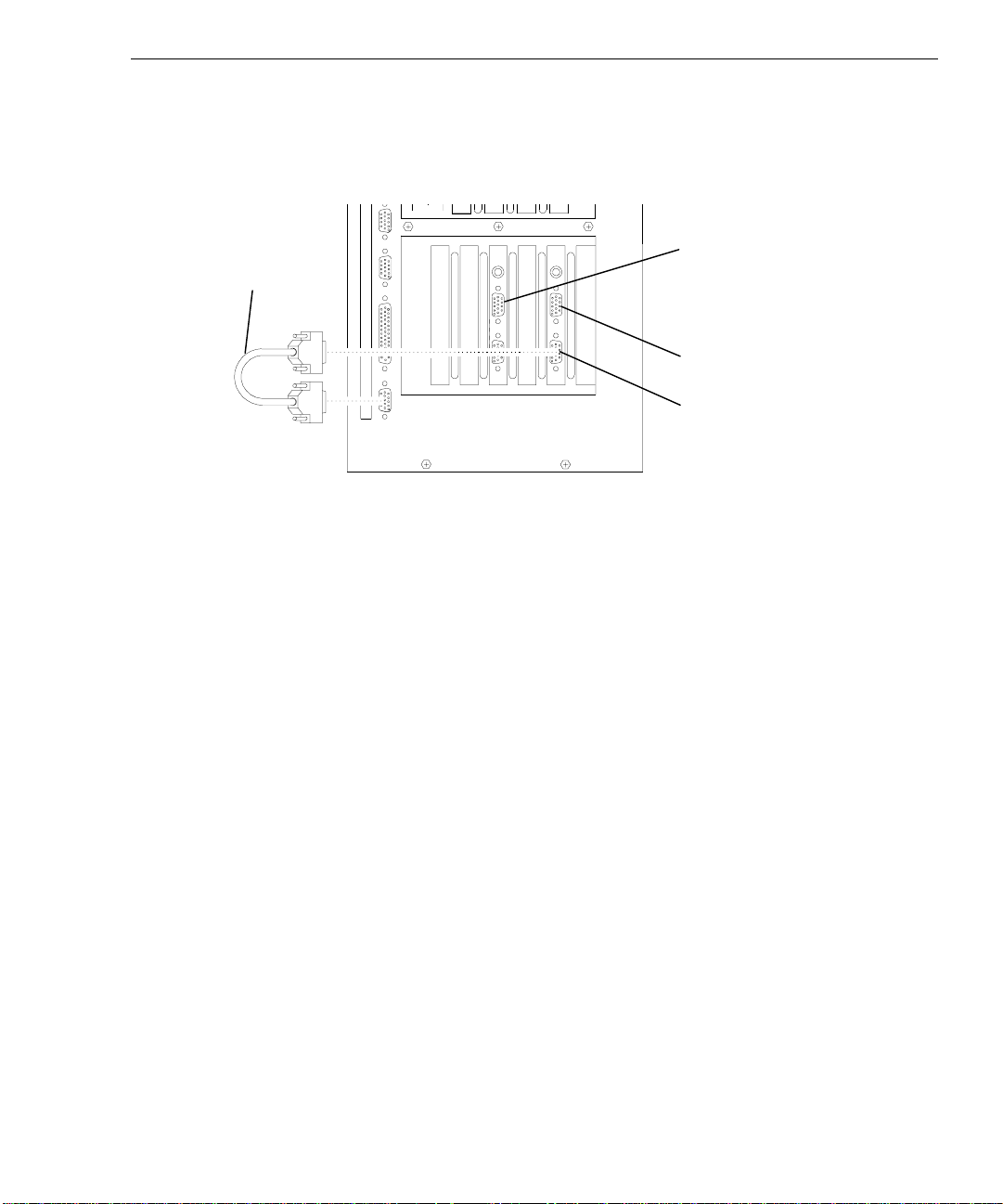
Dual-screen Z10 in a deskside system: Connect the monitor cables from the primary
monitor and the secondary monitor to the Video ports shown in the following figure. Connect
the VGA loopback cable as shown in the following figure.
VGA
Loopback
Cable
Video Port PCI Slot 3
Secondar
Video Port PCI Slot 2
Primar
VGA Port (Primary)
Page 29
Dual-screen Z10-T in a deskside system: Connect the monitor cables from the primary
(
y)
(
y)
monitor and the secondary monitor to the Video ports shown in the following figure. Connect
the VGA loopback cable as shown in the following figure.
VGA
Loopback
Cable
Installing the Video Display Driver
17
Video Port PCI Slot 4
Secondar
Video Port PCI Slot 2
Primar
VGA Port (Primary)
As an aid to troubleshooting, or should it become necessary to re-install the video display
driver, this section describes installing the Intergraph video display driver for Z10 or Z10-T.
The system must be running Windows NT to install the video display driver.
NOTE The video display driver for Z10 and Z10-T is different from the video display driver for Z13
and Z25.
To install the video display driver:
1. Turn on system power and log on to the Windows NT operating system.
2. Open Display in the Windows NT Control Panel. The Display Properties dialog displays.
3. Select the Settings tab. The Settings page displays.
4. Select Display Type. The Display Type dialog displays.
5. Select Change. The Change Display dialog displays.
6. Select Have Disk.
7. Insert the diskette containing the Intergraph video display driver into the floppy disk
drive; then, select OK.
8. At Change Display, select OK.
9. At the third-party driver warning, select YES.
10. At the Installing Driver dialog, select OK.
Page 30

18
11. At the Display Type dialog, select Close.
12. If desired, configure the video display according to the system configuration and your
preferences. Refer to your system documentation, or select a setting and press
more information.
13. Select Apply at the bottom of the dialog to apply the attributes.
14. Remove the diskette from the floppy disk drive.
15. Restart the system.
Troubleshooting
This section contains troubleshooting procedures to help determine which hardware assembly
to return for repair, if you suspect a hardware problem. If problems persist, contact the
Intergraph Customer Response Center at 1-800-633-7248.
Diagnostics
Diagnostic utilities for checking the graphics boards and instructions for using them are
available on the Intergraph Bulletin Board Service (IBBS). Refer to the front of this guide for
instructions to access the IBBS and obtain files.
F1, for
Video Display
The following table lists some common video configuration problems.
Problem
Display is black, not synchronized,
or distorted.
Monitor does not support a
selected resolution or refresh rate.
Two Z10 boards or two Z10-T
board sets installed, but you cannot
select the Dual Screen option.
A dim line, rolling vertically, is
visible on the screen.
Action
Restart Windows NT in VGA mode.
Select a supported resolution and refresh rate.
Verify proper installation of both Z10 boards or
Z10-T board sets (only one board or board set
was detected).
Verify proper installation of the clock sync cable.
Page 31

Problem Action
No VGA bootup screen. Check the VGA loopback cable. Disconnect the
Obtaining a Usable Video Resolution
The system operates in VGA mode when the Intergraph video display driver is not running to
accommodate all monitor types. VGA mode is used during initial installation of the video
display driver and when experiencing video problems.
If you select a resolution that causes the monitor to display incorrectly, do not press
CTRL+ALT+DEL to log on to the Windows NT operating system. Instead, use the Last Known
Good option to return to the last known good configuration recorded by Windows NT.
To use the Last Known Good option:
1. Restart the system.
19
monitor cable from the Video port and connect it
to the VGA port. If no display, check the system
board, monitor, monitor cable, and power to the
monitor.
2. Press the space bar at the following prompt:
Press space bar NOW to invoke the Last Known Good Menu
If using the Last Known Good option fails to correct the video display problems, you can
obtain a functional video resolution by restarting the system in VGA mode.
To restart the system in VGA mode:
1. Restart the system.
2. At the boot screen, select the following option:
Windows NT Workstation Version 4.00 [VGA mode]
Determining a Defective Unit
To determine a defective unit:
1. Save and exit from all files, if possible.
2. Shut down Windows NT, if possible.
3. Turn off the power to the monitor and to the system base unit.
CAUTION Always turn off the power to the workstation before connecting or disconnecting the cables.
4. Check and reseat all board and cable connections as needed.
Page 32

20
5. Turn on the power to the monitor. If the Power On LED does not illuminate, return the
monitor.
NOTE After a period of inactivity, the monitor enters a power saving mode. On Intergraph Multi-sync
monitors, the Power On LED on the front of the monitor will change from green to yellow to
indicate the power saving mode is active.
6. Turn on the power to the system base unit. If the Power On LED on the base unit does
not illuminate or if the BIOS beep codes indicate a failure, return the workstation.
7. If the monitor display is distorted, ensure the software setup is correct for the monitor
type.
If the software setup is correct, use a similar type monitor (if available and functioning
properly) to determine if the workstation is defective.
Page 33

3 Upgrading or Replacing Z13,
Z25, and V25
This chapter describes installing or replacing a RealiZm Z13, Z25, or V25 graphics
accelerator in a TDZ workstation. It provides instructions for the following:
u
Installing optional texture memory on Z13, Z25, and V25
u
Replacing Z13, Z25, or V25, or installing an optional Geometry Accelerator
u
Installing a Z13, Z25, or V25 dual-screen upgrade
u
Connecting the video cables
u
Installing the video display driver
u
Troubleshooting the installation
Refer to your system’s hardware documentation for detailed information on opening and
closing the system, avoiding electrostatic discharge, and installing and replacing option
boards.
21
If an item is missing or damaged, notify the Intergraph Customer Response Center at
1-800-633-7248 immediately.
Precautions
Static electricity can damage the components inside the system base unit, and can damage
texture memory or graphics accelerator boards. To minimize the possibility of electrostatic
discharge, do the following:
u
Do not remove texture memory or a graphics accelerator board from its antistatic bag
until you are ready to install it.
u
Handle texture memory or a graphics accelerator board as little as possible and by the
edges only. Do not drop texture memory or a graphics accelerator board, and do not
expose either to extremes of temperature or moisture.
u
Use an antistatic foam pad to support a graphics accelerator board when installing texture
memory.
u
Use an antistatic wrist strap when handling texture memory or a graphics accelerator
board. There is no increased risk of electrical shock when using the wrist strap. If the
wrist strap does not snugly contact bare skin, static protection will not be effective.
Page 34

22
To use an antistatic wrist strap:
1. Remove the antistatic wrist strap from its envelope. Unfold the wrist strap and wrap the
exposed adhesive side firmly around your bare wrist.
2. Peel the liner from the wrist strap copper foil; then attach the adhesive side of the copper
foil to a bare metal surface (electrical ground) inside the system base unit.
Installing Texture Memory
This section describes installing texture memory on a Z13, Z25, or V25 board. The texture
memory system on a Z13, Z25, or V25 board contains two sockets for dual inline memory
modules (DIMMs).
Intergraph upgrade kits are available for 4 MB, 16 MB, 32 MB, and 64 MB of texture
memory. Each kit contains two DIMMs, an antistatic foam pad to support the graphics
accelerator board, and an antistatic wrist strap. Texture memory for V25 ranges in size from
16 MB to 64 MB.
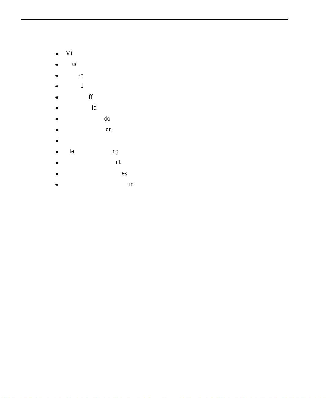
NOTE You must remove the Z13, Z25, or V25 board from the system to install texture memory.
The following figure shows the location of the texture memory sockets on a Z13 board.
Texture
Memory
Sockets
The following figure shows the location of the texture memory sockets on a Z25 or V25
board. You must remove the DIMM access cover to install texture memory.
Page 35

Texture
Memory
Sockets
DIMM
Access
Cover
NOTE For proper operation, you must install DIMMs of the same memory size, and you must fill both
sockets.
23
To install texture memory:
1. Remove the Z13, Z25, or V25 board from the system. Refer to “Replacing Z13, Z25,
V25, or Geometry Accelerator” later in this chapter for instructions.
2. Place the board on the antistatic foam pad for protection and support.
CAUTION Failure to use the antistatic foam pad could cause damage to the board.
3. For a Z25 or V25 board, remove the DIMM access cover.
4. Remove a DIMM from its static protective bag.
CAUTION Do not bend, twist or drop DIMMs. They may be damaged as a result.
5. Align the DIMM notches with the keys in one of the texture memory sockets on the
board, and insert the DIMM into the socket. Refer to the following figure.
Page 36

24
6. Push on the top edge of the DIMM until it snaps into the socket. Refer to the following
figure.
DIMM
7. Repeat steps 4 through 6 for the second DIMM.
8. For a Z25 or V25 board, replace the DIMM access cover.
9. Replace the board into the system.
10. Close the system base unit.
11. Turn on system power and log on to the Windows NT operating system.
12. Open Display in the Windows NT Control Panel. The Hardware Settings page of the
Display Properties dialog should display the proper texture memory size. If not, shut
down and power off the system. Ensure that both DIMMs are properly seated in their
sockets, and that both DIMMs are the same memory size.
Replacing Z13, Z25, V25, or Geometry Accelerator
This section describes replacing a Z13, Z25, V25, or optional Geometry Accelerator board in
a desktop or deskside TDZ workstation. The procedure also describes installing a new
Geometry Accelerator board.
An installed Z13, Z25, or V25 board requires two adjacent PCI slots. An installed Geometry
Accelerator board requires one PCI slot.
To replace a Z13, Z25, V25, or Geometry Accelerator board:
1. Shut down the system and turn off system power.
2. If replacing a Z13, Z25, or V25 board, disconnect the cables from the Video ports on the
back of the system base unit.
Page 37

3. Open the system base unit as required to gain access to the PCI option board slots. Slots
are identified in “Connecting the Video Cables” later in this chapter.
4. If a Geometry Accelerator board is already installed in a single-screen desktop
configuration, disconnect the Vertex data bus between it and the graphics board. The
following figure shows one Z13, Z25, or V25 board.
Geometry
Accelerator
Vertex
Data
Bus
Z13, Z25, or
V25
25
If a Geometry Accelerator board is already installed in a dual-screen deskside
configuration, disconnect the Vertex data bus between it and the graphics boards; then
disconnect the clock sync cable between the graphics boards. The following figure shows
two Z13, Z25, or V25 boards.
Z13, Z25, or
DualScreen
Vertex
Data
Bus
V25
Clock Sync
Cable
Geometry
Accelerator
5. Use a quarter-inch nutdriver to remove the screws that secure the board to the system
chassis. Retain the screws.
Page 38

26
If installing a new Geometry Accelerator board, use a quarter-inch nutdriver to remove
the blanking plate from the following slot:
Desktop system: PCI slot 1
Deskside system: PCI slot 5
Retain the screw.
6. Remove the installed board from the system.
7. Install the new Z13, Z25, V25, or Geometry Accelerator board in the slots from which
you removed the previously installed boards.
If installing a new Geometry Accelerator board, install the board in the PCI slot opened in
step 5.
8. Install the screws that were previously removed to secure the Z13, Z25, V25, or
Geometry Accelerator board to the system chassis.
9. If a Geometry Accelerator board is installed, connect the Vertex data bus between it and
the graphics board(s). Refer to the figures in step 4.
NOTE The connector of the Vertex data bus can be installed in only one orientation.
10. If replacing Z13, Z25, or V25 in a dual-screen deskside configuration, connect the clock
sync cable between the graphics boards. Refer to the figures in step 4.
CAUTION The clock sync cable installs only one way. Do not force the keyed connector. Ensure pin 1
of both cable connectors engages pin 1 on both board connectors. The black wire connects
to pin 4.
11. Close the system base unit.
12. Go to “Connecting the Video Cables” later in this chapter to connect the monitor cables.
Installing a Dual-Screen Upgrade
A dual-screen upgrade provides components to upgrade a TDZ deskside workstation from a
single-screen configuration to a dual-screen configuration. Verify that you have the following
items.
u
Z13, Z25, or V25 board
u
Vertex data bus for dual-screen configuration (used only if optional Geometry
Accelerator is installed)
u
Clock sync cable
u
Antistatic wrist strap
NOTE You cannot install a dual-screen upgrade in a desktop system.
Page 39

27
If an item is missing or damaged, notify the Intergraph Customer Response Center at
1-800-633-7248 immediately.
To install a dual-screen upgrade:
1. Shut down the system and turn off system power.
2. Disconnect the cable from the Video port on the back of the system base unit.
3. Open the system base unit as required to gain access to the PCI option board slots. Slots
are identified in “Connecting the Video Cables” later in this chapter.
4. Use a quarter-inch nutdriver to remove the blanking plates from PCI slots 1 and 2. Retain
the screws.
5. Install the new Z13, Z25, or V25 board in PCI slots 1 and 2.
In a dual-screen configuration, the primary and secondary Z13, Z25, and V25 graphics
accelerators are determined as follows:
Primary: Board installed in PCI slots 1 and 2
Secondary: Board installed in PCI slots 3 and 4
6. Install the screws that were previously removed to secure the board to the system chassis.
7. If a Geometry Accelerator board is installed, connect the dual-screen Vertex data bus
between it and the graphics boards. The following figure shows two Z13, Z25, or V25
boards.
NOTE The connectors of the dual-screen Vertex data bus can be installed in only one orientation.
Z13, Z25, or
DualScreen
Vertex
Data
Bus
V25
Clock Sync
Cable
Geometry
Accelerator
8. Install the clock sync cable between the two Z13, Z25, or V25 boards shown in the
previous figure.
Page 40

28
CAUTION The clock sync cable installs only one way. Do not force the keyed connector. Ensure pin 1
of both cable connectors engages pin 1 on both board connectors. The black wire connects
to pin 4.
9. Close the system base unit.
10. Go to “Connecting the Video Cables” in this chapter to connect the monitor cables.
11. Restart the system and log on to the Windows NT operating system.
12. Use Display in the Windows NT Control Panel to configure the video display driver to
recognize dual screens. Refer to Chapter 1 for more information.
Connecting the Video Cables
After replacing Z13, Z25, or V25, or installing a dual-screen upgrade in a TDZ workstation,
use the following instructions to connect the monitor cables as required.
CAUTION Do not connect the monitor cables to the VGA ports. If you do, the video will not display.
Z13, Z25, or V25 in a desktop system: Connect the monitor cable to the Video port shown
in the following figure.
Video Port PCI Slot 2
VGA Port (not used)
Page 41

Single-screen Z13, Z25, or V25 in a deskside system: Connect the monitor cable to the
(Primary)
(Secondary)
Video port shown in the following figure.
Video Port PCI Slot 3
VGA Port (not used)
Dual-screen Z13, Z25, or V25 in a deskside system: Connect the monitor cables from the
primary monitor and the secondary monitor to the Video ports shown in the following figure.
29
Video Port PCI Slot 3
Video Port PCI Slot 1
VGA Ports (not used)
Page 42

30
Installing the Video Display Driver
As an aid to troubleshooting, or should it become necessary to re-install the video display
driver, this section describes installing the Intergraph video display driver for Z13, Z25, and
V25. The system must be running Windows NT to install the video display driver.
NOTE The video display driver for Z13, Z25, and V25 is different from the vide o display driver for
Z10.
To install the video display driver:
1. Turn on system power and log on to the Windows NT operating system.
2. Open Display in the Windows NT Control Panel. The Display Properties dialog displays.
3. Select Settings. The Settings page displays.
4. Select Display Type. The Display Type dialog displays.
5. Select Change. The Change Display dialog displays.
6. Select Have Disk.
7. Insert the diskette containing the Intergraph video display driver into the floppy disk
drive; then, select OK.
8. At Change Display, select OK.
9. At the third-party driver warning, select YES.
10. At the Installing Driver dialog, select OK.
11. At the Display Type dialog, select Close.
12. If desired, configure the video display according to the system configuration and your
preferences. Refer to your system documentation, or select a setting and press
more information.
13. Select Apply at the bottom of the dialog to apply the attributes.
14. Remove the diskette from the floppy disk drive.
15. Restart the system.
F1, for
Page 43

Troubleshooting
This section contains troubleshooting procedures to help determine which hardware assembly
to return for repair, if you suspect a hardware problem. If problems persist, contact the
Intergraph Customer Response Center at 1-800-633-7248.
Diagnostics
Diagnostic utilities for checking the graphics boards and instructions for using them are
available on the Intergraph Bulletin Board Service (IBBS). Refer to the front of this guide for
instructions to access the IBBS and obtain files.
Video Display
The following table lists some common video configuration problems.
31
Problem
Display is black, not synchronized,
or distorted.
Monitor does not support a
selected resolution or refresh rate.
Two graphics boards installed, but
you cannot select the Dual Screen
option.
A dim line, rolling vertically, is
visible on the screen.
Obtaining a Usable Video Resolution
The system operates in VGA mode when the Intergraph video display driver is not running to
accommodate all monitor types. VGA mode is used during initial installation of the video
display driver and when experiencing video problems.
If you select a resolution that causes the monitor to display incorrectly, do not press
CTRL+ALT+DEL to log on to the Windows NT operating system. Instead, use the Last Known
Good option to return to the last known good configuration recorded by Windows NT.
To use the Last Known Good option:
1. Restart the system.
Action
Restart Windows NT in VGA mode.
Select a supported resolution and refresh rate.
Verify proper installation of all RealiZm graphics
boards (only one board was detected).
Verify proper installation of the clock sync cable.
2. Press the space bar at the following prompt:
Page 44

32
Press space bar NOW to invoke the Last Known Good Menu
If using the Last Known Good option fails to correct the video display problems, you can
obtain a functional video resolution by restarting the system in VGA mode.
To restart the system in VGA mode:
1. Restart the system.
2. At the boot screen, select the following option:
Windows NT Workstation Version 4.00 [VGA mode]
Determining a Defective Unit
To determine a defective unit:
1. Save and exit from all files, if possible.
2. Shut down Windows NT, if possible.
3. Turn off the power to the monitor and to the system base unit.
CAUTION Always turn off the power to the workstation before connecting or disconnecting the cables.
4. Check and reseat all board and cable connections as needed.
5. Turn on the power to the monitor. If the Power On LED does not illuminate, return the
monitor.
NOTE After a period of inactivity, the monitor enters a power saving mode. On Intergraph Multi-sync
monitors, the Power On LED on the front of the monitor will change from green to yellow to
indicate the power saving mode is active.
6. Turn on the power to the system base unit. If the Power On LED on the base unit does
not illuminate or if the BIOS beep codes indicate a failure, return the workstation.
7. If the monitor display is distorted, ensure the software setup is correct for the monitor
type.
If the software setup is correct, use a similar type monitor (if available and functioning
properly) to determine if the workstation is defective.
Page 45

4 Technical Description
This chapter provides a technical description of the RealiZm graphics accelerators and the
optional Geometry Accelerator.
Rasterization Accelerator Features
RealiZm graphics accelerators include advanced features to accelerate the rasterization of
computer graphics and enhance visual impact. The integrated Z10, Z13, Z25, and V25
rasterization accelerators comprise a Peripheral Component Interconnect (PCI) Bus Interface,
Graphics Engine, Texture Processor, and Frame Buffer.
The PCI Bus Interface features:
u
PCI compatible bus interface
33
u
High-speed direct memory access (DMA) engine
u
Interface for Geometry Accelerator (Z13, Z25, and V25)
The Graphics Engine features:
u
High-level vertex interface
u
Gouraud shading support
u
Symbolized vector support
u
Antialiased vector support
u
Sub-pixel accuracy
u
Window clipping (Z13, Z25, and V25)
The Texture Processor features:
u
Advanced texture processor hardware
u
Texture memory
u
MIP-mapping support with trilinear interpolation
Page 46
34
The Frame Buffer features:
u
Video planes
u
True-color image buffer
u
High-resolution Z buffer
u
Stencil buffer (Z13, Z25, and V25)
u
Alpha buffer (Z13, Z25, and V25)
u
Multiple video lookup tables
u
Window-mode double buffering
u
Gamma correction
u
Hardware cursor
u
Stereoscopic viewing
u
Multiple video resolutions
u
High-speed screen refresh
u
Genlock support for dual monitors
PCI Bus Interface
The Z10, Z13, Z25, and V25 graphics accelerators are 32-bit PCI peripherals.
PCI-Compatible Bus Interface
The PCI direct memory access (PCIDMA) application-specific integrated circuit (ASIC)
provides the PCI-compatible bus interface for these accelerators, including bus mastership
capability. This interface provides a high-speed, industry-standard connection between the
host processor and the graphics accelerator.
High-Speed DMA Engine
The Rasterization Accelerator uses a high-speed DMA engine to accelerate PCI bus data
transfers. The DMA engine transfers data in bursts without intervention from the host
processor. These unattended transfers free the host processor from transferring massive
amounts of graphics data over the PCI bus.
Page 47

Interface for Geometry Accelerator (Z13, Z25, and V25)
Geometry calculations, such as lighting and perspective adjustment, are performed either by
the host processor or by an optional Geometry Accelerator. If installed, the Geometry
Accelerator sends vertex data to the Rasterization Accelerator via a dedicated connector. A
direct connection allows data to flow quickly to the Rasterization Accelerator, which enhances
performance.
Graphics Engine
The Graphics Engine is the core of the Rasterization Accelerator. It accelerates the translation
of high-level graphics requests into pixel-oriented requests through derivative calculations and
span iteration. It then coordinates the movement of pixels to the Frame Buffer.
High-Level Vertex Interface
The Rasterization Accelerator allows the software to send vertex data for triangles and vectors
in multiple formats. Supported formats include 8-bit packed integer, 16-bit packed integer,
32-bit integer, single-precision floating point, and double-precision floating point.
The host processor achieves higher performance because it does not convert data that is native
to a particular application. To conserve bandwidth, the application optionally loads constant
color and Z values to avoid sending them with each vertex.
35
Gouraud Shading Support
The Graphics Engine supports smooth shading of 3D triangle meshes with the Gouraud
algorithm. High performance hardware accomplishes the shading of the entire triangle,
including color and depth derivative calculations and pixel interpolation. The hardware also
allows maximum update rates with minimum load on the host processor.
Symbolized Vector Support
The Graphics Engine supports the application of any user-supplied, two-color pattern onto
vectors without performance degradation. Dotted or dashed lines are examples of symbolized
vectors.
Antialiased Vector Support
Hardware support of antialiased vectors eliminates the jagged appearance of vectors on
standard raster displays.
Page 48

36
Sub-Pixel Accuracy
The Graphics Engine uses sub-pixel accuracy for improving the quality of the graphics image.
Sub-pixel accuracy ensures adjacent polygons and vectors join smoothly.
Window Clipping (Z13, Z25, and V25)
While rendering triangles and vectors, the Graphics Engine discards pixels that would fall
outside the region of the target window. Hardware clipping in this fashion alleviates the
burden of checking objects in software before sending them to the graphics system.
Texture Processor
Texturing is available on RealiZm graphics accelerators that have a texturing accelerator
(Z10) or texture memory (Z13, Z25, and V25) installed. Texturing is the process of applying
a pattern, represented in memory as a two-dimensional array of image color values, to the
surface of a 3D graphical object. For example, a wood grain pattern can be texture-mapped to
the surface of an object, such as a desk, to enhance realism of the image.
Another example of texture mapping is draping a land image from a satellite over a digital
terrain model to create a 3D representation. The Texture Processor module of the RealiZm
graphics accelerators provides a dramatic performance increase for advanced texture
processing when compared with software algorithms alone.
Advanced Texture Processor Hardware
The Texture Processor has its own ASICs on the Z10, and is integrated into the Graphics
Engine/Texture Processor ASIC on the Z13, Z25, and the V25. It supports 32-bit textures,
one byte for each of the color components: red, green, blue, and alpha.
Texture Memory
Texture memory is 8 MB in a Z10 with the hardware texture option, providing up to 2
MTexels of texture maps. If installed in a Z13 or Z25, texture memory ranges in size from 4
MB to 64 MB, providing from 1 MTexels to 16 MTexels of texture maps. If installed in V25,
texture memory ranges in size from 16 MB to 64 MB, providing from 4 MTexels to 16
MTexels of texture maps.
Page 49

MIP-Mapping Support with Trilinear Interpolation
The Texture Processor allows various sizes of texture maps to coexist in texture memory.
Different MIP (multum in parvo -- many things in a small place) maps allow the appropriate
level of detail to be shown based on viewing distance. The Texture Processor chooses four
texels nearest the actual texel value from each of the nearest two MIP maps (for a total of
eight texels). The Texture Processor blends the eight texels to produce the actual texel value
by using trilinear interpolation.
Frame Buffer
The RealiZm Frame Buffers are full-featured: Their deep pixel formats provide a flexible
environment for applications with hardware acceleration. For example, double-buffered
overlay planes provide the ability to annotate text and graphics over a 3D image in the image
buffer. Both image buffers have access to one of four video lookup tables (VLTs). The image
VLT selection planes select the VLT to use. The mask planes allow for access control of the
various drawing planes (for example, image or overlay). The image and overlay buffer
selection control planes determine the buffer to display on a pixel-by-pixel basis. Other
features include support of a wide variety of displays operating at high resolution.
Video Planes
37
Z10 supports 84 bits-per-pixel plane sets, and Z10-T supports 90 bits-per-pixel configurations,
as summarized in the following table:
Video Plane Sets
Image (red, green, blue), front buffer 24 24
Image (red, green, blue), back buffer 24 24
Overlay, front buffer 1 4
Overlay, back buffer 1 4
Image, VLT selection, front buffer 3 3
Image, VLT selection, back buffer 3 3
Z buffer 24 24
Mask (pixel access control) 2 2
Image, window control 1 1
Overlay, window control 1 1
Z13, Z25, and V25 support two plane set configurations: 100 bits-per-pixel and 128 bits-perpixel. The 128 bits-per-pixel mode is supported at resolutions slightly less than the maximum.
For example, the Z25 supports 128 bits-per-pixel up to maximum resolution of 2 Mpixel
(1600 x 1200) and 100 bits-per-pixel for a resolution of 2.5 Mpixel (1824 x 1368).
84 Bits/Pixel 90 Bits/Pixel
Page 50

38
The following table summarizes the video plane sets for the Z13, Z25, and V25 accelerators.
Video Plane Sets
100 Bits/Pixel 128 Bits/Pixel
Image (red, green, blue), front buffer 24 24
Image (red, green, blue), back buffer 24 24
Overlay, front buffer 4 8
Overlay, back buffer 4 8
Image, VLT selection, front buffer 4 4
Image, VLT selection, back buffer 4 4
Z buffer 24 32
Mask (pixel access control) 2 4
Image, buffer selection control 1 1
Overlay, buffer selection control 1 1
Alpha 0 8
Stencil 6 8
Fast Clear Front Buffer 1 1
Fast Clear Back Buffer 1 1
True-Color Image Buffer
The true-color image buffer is 24 bits and double-buffered. It contains the red, green, and
blue components of the image with 8 bits per component to provide 16.7 million colors.
There are two copies, or buffers, of image data: a front buffer and a back buffer. Two buffers
enhance smooth animation, since applications may update the back buffer while displaying the
front buffer.
High-Resolution Z Buffer
The Z buffer holds 24 bits of depth information (Z10) or up to 32 bits of depth information
(Z13, Z25, and V25). Depth represents a distance from the observer’s eye to an object in a
scene. A large Z buffer enables representation of a large number of unique depth values,
which provides a more accurate rendering of scenes with large depth separation between
objects.
Stencil Buffer (Z13, Z25, and V25)
The stencil buffer holds up to 8-bits of stencil information. This buffer is a general-purpose
resource for OpenGL applications. In a typical case, stenciling inhibits writes to portions of
an application’s window, but allows writes to other portions. The Frame Buffer accelerates
building the values in the stencil buffer, and also accelerates the action of inhibiting or
allowing writes on a per-pixel basis.
Page 51

Alpha Buffer (Z13, Z25, and V25)
The alpha buffer holds up to 8-bits of alpha information. Alpha planes and alpha blending
logic in the Frame Buffer assist the application in rendering scenes more realistically. Special
effects that might result from alpha blending include transparency or tinting.
Multiple Video Lookup Tables
The Frame Buffer includes up to four VLTs. The VLTs provide multiple color palettes
simultaneously for color remapping and advanced color refinement.
Window-Mode Double-Buffering
Window-mode double-buffering allows multiple windows to display simultaneously from
different buffers.
Gamma Correction
10-bit gamma VLTs and 10-bit digital-to-analog converters (DACs) allow fine control of
displayed colors without color degradation.
39
Hardware Cursor
Hardware superimposes the cursor image over the video stream in real time, minimizing the
cursor management tasks required by the host processor.
Stereoscopic Viewing
RealiZm graphics accelerators support the display of stereo images. Stereoscopic viewing
requires a stereo-ready monitor and infrared shutter glasses with emitter module.
Multiple Video Resolutions
RealiZm graphics accelerators include programmable pixel clock generation and video timing
logic. This allows support of a wide variety of monitors with multiple video resolutions and
refresh rates. Programmable video timing also allows future monitor upgrades with only a
software driver change. Supported resolutions range from 640 x 480 up to 1152 x 864 (Z10)
or 1280 x 1024 (Z13) or 1824 x 1368 (Z25 and V25). Refer to Chapter 6 for additional
information on supported monitor resolutions.
Page 52

40
High-Speed Screen Refresh
High-speed screen refresh provides flicker-free displays up to 76 Hz (Z10) or 85 Hz (Z13,
Z25, and V25) for most screen resolutions.
Genlock Support for Dual Monitors
A clock sync cable installed between RealiZm board sets synchronizes the monitors in a dualmonitor configuration. This Genlock method eliminates the visual beat frequency effect that
may occur when placing two monitors close to each other.
Rasterization Accelerator Functions
Graphics Device Interface (GDI) is the library of functions that the Windows NT operating
system uses to create and manipulate 2D computer images. RealiZm rasterization hardware
accelerates many GDI functions.
OpenGL is an industry standard library of functions used to create and manipulate 3D
computer images. OpenGL functions, as a part of the Windows NT operating system, can be
performed by the host processor. RealiZm hardware accelerators greatly improve OpenGL
performance.
For the Z13, Z25, and V25 accelerators, either the host processor or an optional Geometry
Accelerator performs the geometry stage of the OpenGL processing. While the Geometry
Accelerator processes OpenGL requests, the host processor is freed to perform application and
database operations. This parallel processing results in unprecedented speed to generate and
manipulate realistic images.
As shown in the following figure, the Rasterization Accelerator includes:
u
Pixelization Accelerator
u
Texture Processor (optional)
u
Frame Buffer
Page 53

Application
Using
OpenGL
Geometry Processing
Geometry Accelerator
(Z13, Z25, and V25 Optional)
41
Rasterization
Accelerator
Pixelization Accelerator
The Pixelization Accelerator consists of PCIDMA, graphics first-in-first-out (FIFO), and the
Graphics Engine. The standard PCI bus provides high bandwidth support for the transfer of
graphics data between the host processor and the Rasterization Accelerator. If the Geometry
Accelerator is present (for Z13, Z25, and V25), then the system transfers data from the host
processor to the Geometry Accelerator, which then transfers data to the Rasterization
Accelerator via a dedicated bus.
The Rasterization Accelerator receives GDI or OpenGL element requests from the host
processor (or from the Geometry Accelerator, if present), through the PCIDMA and graphics
FIFO. Element types include triangles, triangle meshes, lines, line strings, and others. The
Graphics Engine ASIC converts the elements to pixels and routes them through the resolvers
to video memory.
Pixelization
Accelerator
Frame Buffer
Monitor
Texture
Processor
(Optional)
The Rasterization Accelerator also performs region fills, bit expands, and BIT BLock Transfer
(BITBLT) operations. Optional processing of the pixels is performed by the Texture
Processor prior to the Graphics Engine sending them to the resolvers.
Page 54

42
Texture Processor
The Texture Processor resides in dedicated ASICs (Z10) or is physically part of the Graphics
Engine/Texture Processor ASIC (Z13, Z25, and V25). It supports 32-bit textures: 8 bits for
each color component (red, green, blue, and alpha).
The Texture Processor receives two types of setup parameters from the Graphics Engine: one
type for triangles and one type for pixel spans within a triangle. The triangle setup parameters
consist of texturing control information and texture coordinate derivatives. The pixel span
setup parameters consist of initial texture coordinates. These texturing setup parameters
control the interpolation of the texture coordinate values. The texture processors correct for
perspective during texture coordinate interpolation and thereby reduce image distortion.
The texture memory is capable of storing several sets of MIP-mapped textures for subsequent
texture mapping. In MIP-mapping, software creates smaller-sized versions of a base texture
and stores them in texture memory. The smaller versions represent the base texture at varying
distances from the viewer’s eye.
The Texture Processor chooses eight texels nearest the actual texel value from the nearest two
MIP maps. The Texture Processor interpolates these eight texels to produce the actual texel
value through the use of trilinear interpolation.
The actual texel value can either replace or blend with the Gouraud shaded pixel value
generated by the Graphics Engine. Finally, the Graphics Engine routes the textured pixels
from the Texture Processor to the resolvers, which write the textured pixels into video
memory.
Frame Buffer
The Frame Buffer consists of the resolvers, video memory, and a DAC. Z10 resolvers control
the flow of digital pixel data from the video memory to the video selector and mappers
(VSMs) and then to the DAC where it is converted to an analog voltage and presented to the
monitor. Refer to the following figure.
Page 55

Z10
RealiZm
Rasterization
Accelerators
Z10 has a total of
12 MB Video Memory
and two resolvers
PCI Bus
PCIDMA
Graphics FIFO
Graphics Engine
Request Handler
Slope Calculation
Span Generation
Pixel Interpolation
IZ Bus
43
Texture
Memory
8 MB
(Optional)
Four Texture
Processors
R, G, B, A
(Optional)
Resolver
Video
Memory
6 MB
Video
Selector and
Mapper
Digital To Analog Converter
Monitor
Selector and
Resolver
Video
Memory
6 MB
Video
Mapper
Page 56

44
Z13, Z25, and V25 resolvers retrieve digital pixel data from video memory, and send it to the
DAC where it is converted to an analog voltage and presented to the monitor.
PCI Bus
Z13, Z25, and
V25 RealiZm
Rasterization
Accelerators
(Z13 shown)
Z13 has a total of
16 MB Video Memory
and two dual resolvers.
Both Z25 and V25 have
a total of 32 MB Video
Memory and four dual
resolvers.
Video
Memory
8MB
PCIDMA
Graphics FIFO
Graphics Engine
Request Handler
Slope Calculation
Span Generation
Pixel Interpolation
IZ Bus
Dual
Resolver
Digital To Analog Converter
Video
Memory
8MB
Texture
Memory
(Optional)
Texture
Processor
Dual
Resolver
Monitor
Page 57

Geometry Accelerator Features and Functions
The Geometry Accelerator available for use with Z13, Z25, and V25 employs the following
features and functions to accelerate the geometry processing requirements of computer
graphics.
u
High-speed graphics DMA engine
u
MIMD DSP architecture
u
Sequence Controller
High-Speed Graphics DMA Engine
The Geometry Accelerator uses high-speed DMA engines to accelerate PCI bus data transfers.
An independent DMA engine transfers data in bursts and frees the host processor from
transferring massive amounts of graphics data over the PCI bus.
MIMD DSP Architecture
45
The Geometry Accelerator features a multiple instruction multiple data (MIMD) architecture
to harness the power of six floating-point digital signal processors (DSPs) operating in
parallel. The DSPs speed the compute-intensive geometry calculations of 3D graphics. Each
DSP can execute 120 million floating point operations per second (MFLOPS), and contains
10 DMA engines to ensure nonstop data flow to the Sequence Controller.
Sequence Controller
To achieve maximum efficiency in a MIMD architecture, multiple processors operate
independently on multiple data sets. The six Geometry Accelerator DSPs process graphics
requests in turn and may generate output requests in a different order than the input requests.
The Sequence Controller places the output requests into the proper time sequence.
The PCI bus is a high-performance bus capable of operating up to 33 MHz. The Geometry
Accelerator is a 32-bit PCI bus peripheral with bus mastership capability, which uses the PCI
bus to transfer data from the host processor.
Page 58

46
Geometry
Accelerator
PCI Bus
PCIDMA
Input/Output
FIFO
DSP IO Bus
DSP6DSP5DSP4DSP3DSP2DSP1
Sequence Controller
Vertex Data Bus (to Z13, Z25, or V25)
The Geometry Accelerator receives OpenGL requests from the host processor through the
PCIDMA and the input/output (I/O) FIFO. The requests are routed to six independent 32-bit
floating-point DSPs, which process OpenGL requests in parallel. The output requests from
each DSP flow through dedicated ports to the Sequence Controller. The Sequence Controller
time-orders and formats the requests, and then writes them to the Z13, or Z25, or V25 input
FIFO over the dedicated Vertex data bus.
The processing performed by each of the six DSPs includes coordinate transformations,
lighting calculations, and viewport clipping. Clipping is the process of removing elements, or
pieces of elements, not contained within the viewing volume (viewport). The Geometry
Accelerator processes each element specified by OpenGL as supported by the Rasterization
Accelerator.
Page 59

5 Hardware Description
This chapter describes the architecture and hardware implementation of the RealiZm graphics
acclerators and the optional Geometry Accelerator.
Rasterization Accelerator Components
The following figures describe the major components of the Rasterization Accelerator boards
for the Z10, Z13, Z25, and V25.
Z10
The following figure shows the front of a Z10 board:
47
Clock Sync
Connector
VGA
Input
Port
Video Input
Port
Stereo Sync
Port
Video Selector
and Mappers
PCIDMA
Digital to Analog
Converter
Graphics
Engine
Texturing Accelerator
Connector
Video
Memory
Resolvers
Page 60
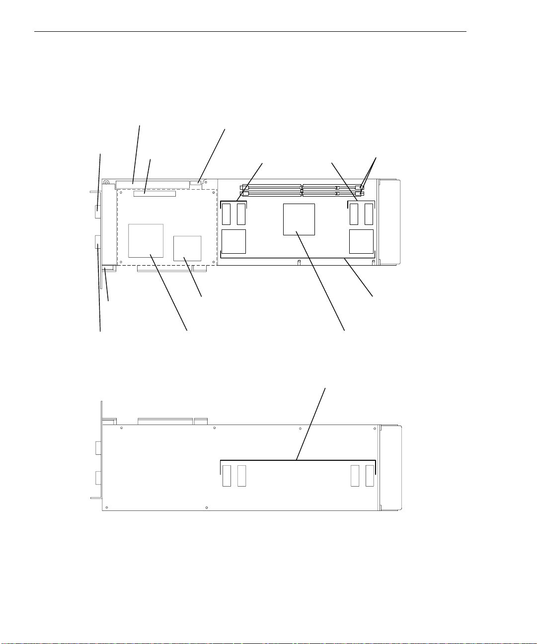
48
)
Z13
The following figure shows the front of a Z13 graphics board:
Vertex Data Bus
Connector
VGA
Input
Port
Stereo Sync
Port
Video Input
Port
VGA Board
Connector
VGA Board (Outline
Digital to Analog
Converter
Clock
Sync
Connector
Video Memory
PCIDMA
The following figure shows the back of a Z13 graphics board:
DIMM
Socket
Dual Resolvers
Graphics Engine/
Texture Processor
Video Memory
Page 61
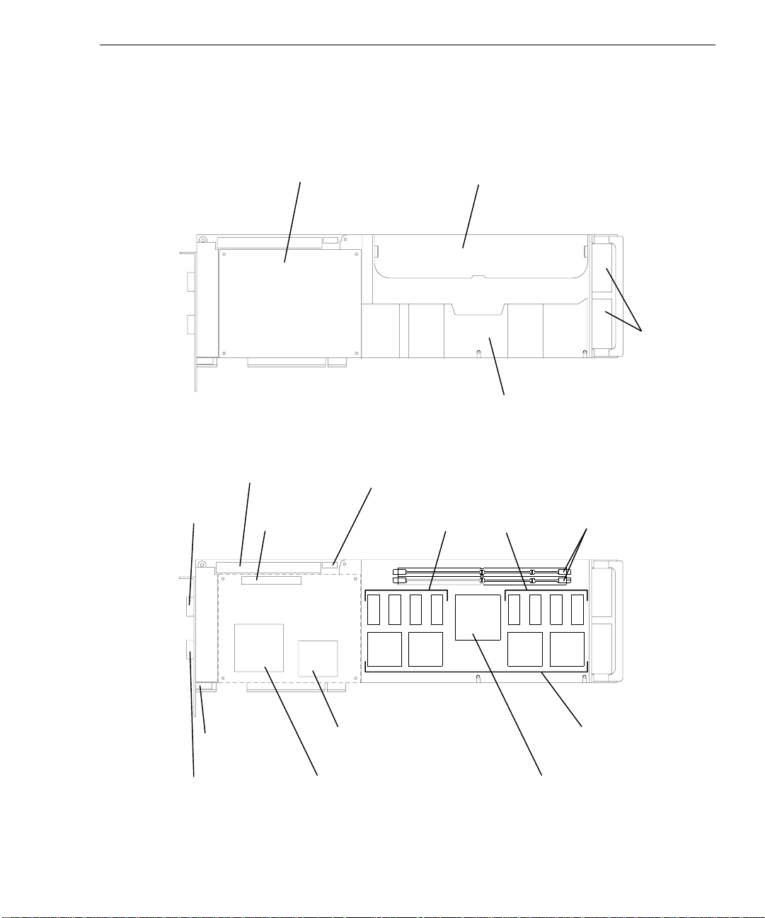
Z25 and V25
)
The following figure shows the front of a Z25 or V25 graphics board with covers in place:
The following figure shows the front of a Z25 or V25 graphics board with covers removed:
VGA Board
49
Texture Memory
Access
Cover
Fans
Cooling Duct
Cover
Vertex Data Bus
Connector
VGA
Input
Port
Stereo Sync
Port
Video Input
Port
VGA Board
Connector
VGA Board (Outline
Clock
Sync
Connector
PCIDMA
Digital to Analog
Converter
Video
Memory
DIMM
Socket
Dual Resolvers
Graphics Engine/
Texture Processor
Page 62

50
PCIDMA
The following figure shows the back of a Z25 or V25 graphics board:
Video Memory
The PCIDMA application-specific integrated circuit (ASIC) is a multichannel, direct memory
access (DMA) engine capable of burst transfers. For OpenGL requests, the Rasterization
Accelerator uses a DMA to send vertex data through the PCIDMA to the graphics engine firstin-first-out (FIFO).
Graphics Engine and Texture Processor
The Graphics Engine ASIC and the Texture Processor are physically separate entities for the
Z10, and integrated within the same ASIC for the Z13, Z25, and the V25.
The Graphics Engine is the main graphics processor for the graphics board and the core of the
Rasterization Accelerator. It takes vertex data from the graphics FIFO and produces spans of
pixel data. The Graphics Engine sends the data to the Frame Buffer over a high-speed pixel
path called the Image/Z (IZ) bus. If texture memory is present, texturing of the pixels occurs
before transfers of data on the IZ bus.
The Graphics Engine uses four major logic blocks to perform the pixel rasterization. They
are: (1) request handler, (2) slope calculation, (3) span generation, and (4) pixel interpolation.
Page 63

Request Handler
The request handler monitors the data output of the graphics FIFO. When data arrives, the
request handler analyzes it and writes it to an appropriate processing block. The request
handler routes vertex data for triangles and lines to the slope calculation block.
Drawing requests (other than vertex data for triangles and lines) such as blits, fills, and bit
expands, bypass the slope calculation and span generation blocks. The request handler routes
this data directly to the pixel interpolation block.
Slope Calculation
The slope calculation block performs the slope calculation part of the rasterization process for
triangles and lines. Floating-point math ensures the accuracy of triangle edges.
The slope calculation block calculates color derivatives, depth derivatives, and edge slopes. It
also adjusts the vertex data to a pixel center for the topmost vertex. The slope calculation
block converts all data to a fixed-point format and routes it to the span generation block.
Span Generation
51
The span generation block performs the span calculation part of the rasterization process for
triangles and lines. The span generation block determines the leftmost x and y coordinates for
each scanline in a triangle. It also calculates the initial color and depth value for each
scanline, and routes the data to the pixel interpolation block.
Pixel Interpolation
The pixel interpolation block is common for all graphics drawing requests. For triangle
meshes, the pixel interpolation block expands the data from the span generation block to pixel
data by successively adding the x-derivative value to the initial color and depth values (z) for
each span.
The pixel interpolation block also sends the (x, y) address and pixel data to the frame buffer
over the IZ bus. The IZ bus is a 64-bit bus with a pixel span protocol to facilitate high data
throughput. This protocol allows burst transfers of pixel data to occur between the
rasterization accelerator and the frame buffer. The maximum burst size is 4096 pixels.
Texture Processor
A Texture Processor is contained in the Graphics Engine/Texture Processor ASIC on the Z13,
Z25, and V25, and as separate ASICs on the Z10. Texturing is the process of applying texture
patterns to the surface of a 3D graphics object to enhance the visual realism of the object, or
of an entire scene.
Page 64

52
The Texture Processor receives instructions from the Graphics Engine via a high-speed bus
and buffers the instructions in a FIFO to enhance performance. The Texture Processor reads
the instructions from the FIFO, and then translates them into reads and writes of texture
memory. Its primary function is to retrieve a group of texels, interpolate among them, and
generate a final color value. This final color value represents the textured color of a pixel.
The Texture Processor places this value into its output FIFO. The Graphics Engine transfers
the pixel’s location and color value from the FIFO to the resolvers for placement into the
frame buffer.
Z10 Texturing Accelerator
The Z10 Texturing Accelerator board communicates with texture memory via a 256-bit bus,
which provides simultaneous access to eight 32-bit texels. Thirty-two bits are essential for
storage of true-color texels, including Alpha, to match the frame buffer’s true-color pixels.
The following figure shows the front of a Z10 Texturing Accelerator board.
Texture Processors
Texture
Processor
Texture
Memory
Rasterization
Accelerator
Connector
Texture
Memory
Page 65

Texture Memory
Texture memory is capable of storing several sets of MIP-mapped textures for subsequent
texture mapping. On the Z10-T, texture memory is fixed at 8 MB. On the Z13, Z25, and the
V25, two DIMM sockets may contain texture memory modules. The texture memory socket is
keyed for proper installation.
The available options for Z13 and Z25 are:
u
4 MB (two 2 MB DIMMs)
u
16 MB (two 8 MB DIMMs)
u
32 MB (two 16 MB DIMMs)
53
Alignment Notches
u
64 MB (two 32 MB DIMMs)
The available options for V25 are:
u
16 MB (two 8 MB DIMMs)
u
32 MB (two 16 MB DIMMs)
u
64 MB (two 32 MB DIMMs)
Resolver A rchitecture
For the Z10, two resolver ASICs perform the memory control function of reading and writing
data to the video memory. They also coordinate the movement of data from the video
memory to the video selector and mapper (VSM) ASIC and digital-to-analog converter
(DAC).
For the Z13, Z25, and the V25, a dual resolver ASIC contains two independent resolver
modules and one screen refresh module. Resolvers perform the memory control function for
reading and writing to the video memory. The screen refresh modules transfer pixel data from
the pair of resolvers to the DAC. A frame buffer consists of two or four dual resolver ASICs.
The Graphics Engine ASIC sends pixel data over the IZ bus to the resolvers’ IZ input FIFOs.
The FIFOs enable the resolvers to accommodate bursts of pixel data without slowing overall
Page 66

54
system performance. The pixel data consists of color (Red, Green, Blue, and Alpha - RGBA)
and depth (Z) data.
The resolver examines pixel data from the input FIFO and determines if it should write the
pixel data to the video memory. The resolver performs Z, mask, stencil (Z13, Z25, and V25
only), and alpha tests to determine if data should be written.
The resolver can perform an Arithmetic and Logic Unit (ALU) operation between the source
data (data from the Graphics Engine) and the destination data (data in video memory). The
operations include logical operations and OpenGL style alpha blend operations.
The resolver performs several different types of memory accesses including reads, writes, or
read-modify-writes. It conserves memory bandwidth by choosing an appropriate type.
Video Memory
The core of the frame buffer is video memory. Resolvers control the flow of data to and from
the video memory. The various implementations of RealiZm accelerators have varying
amounts of video memory: 48 VRAMs provide 12 MB of video memory for Z10; 8 SDRAMs
provide 16 MB of video memory for Z13; and 16 SDRAMs provide 32 MB of video memory
for Z25 and V25.
Video memory stores each pixel with a maximum of 128 bits (Z13, Z25, and V25).
Video Selector and Mapper (Z10 Only)
The display subsystem consists of the VSM ASIC and the DAC. The VSM ASIC receives
pixel data from the video memory. It selects the buffer (front or back), and the data (image or
overlay) to display. The video selection planes select one of the VSM’s four video lookup
tables (VLTs) to map the image data. The VSM sends the mapped result to the DAC.
Digital-to-Analog Converter
The DAC converts pixel data into an analog voltage and sends it to the monitor for display.
The DAC also provides a user-definable 64 x 64 pixel hardware cursor.
Page 67

Geometry Accelerator Components
The following describes the major components of the Geometry Accelerator board available
for use with Z13, Z25, and V25.
55
PCIDMA
PCIDMA
Sequenc
e
The Geometry Accelerator employs the PCIDMA ASIC as the Peripheral Component
Interconnect (PCI) bus interface device. This device has an independent DMA engine to
accelerate the transfer of OpenGL data between the host processor and the Geometry
Accelerator.
The DMA engine transfers data in bursts into the input/output (I/O) FIFO on the Geometry
Accelerator. DMA transfers free the host processor from moving massive amounts of
graphics data across the PCI bus.
I/O FIFO
DSPs
I/O FIFO
The I/O FIFO is a temporary depository for up to 4 KB of data being moved into the
Geometry Accelerator. The I/O FIFO allows DMA transfers to proceed at the maximum
speed of the PCI bus or the I/O bus by avoiding stall conditions.
Page 68

56
DSPs
The core of the Geometry Accelerator is six state of the art digital signal processors (DSPs)
operating in parallel. These are 32-bit floating point processors, each capable of executing
120 million floating-point operations per second (MFLOPS). Each DSP contains 256 KB of
high-speed RAM. Each DSP also has an advanced I/O system with six communication ports
and ten DMA engines. This I/O system allows continual flow of data through the multiple
DSPs and to the Sequence Controller with minimal host processor overhead.
Sequence Controller
The multiple instruction multiple data (MIMD) architecture of the Geometry Accelerator
allows incoming data to be processed concurrently and independently by each of the six DSPs.
This means that the DSP that processes the first input request may not generate the first output
request. Data moves through the DSPs at different rates, depending upon the complexity of
the request.
Since the order of drawing operations must be maintained, this out of order data must be
placed back into the order that it was received. This task is the responsibility of the Sequence
Controller. The Sequence Controller receives data from each of the six DSPs via four
communication ports. The Sequence Controller time-orders the data, and then uses a DMA to
write the data directly to the Rasterization Accelerator via the Vertex data bus. The Sequence
Controller also handles some clipping, and controls the flow of data to multiple Rasterization
Accelerators for dual screen systems.
Page 69

6 Specifications
Standard specifications for RealiZm graphics accelerators are subject to change without
notice.
57
Graphics
Accelerator
Z10 1.0 Mpixels 12 MB VRAM
Z10-T 1.0 Mpixels 12 MB VRAM 8 MB DRAM
Z13 1.3 Mpixels 16 MB SDRAM
Z13-T 1.3 Mpixels 16 MB SDRAM 4 - 64 MB SDRAM
Z13-G 1.3 Mpixels 16 MB SDRAM
Z13-GT 1.3 Mpixels 16 MB SDRAM 4 - 64 MB SDRAM
Z25 2.5 Mpixels 32 MB SDRAM
Z25-T 2.5 Mpixels 32 MB SDRAM 4 - 64 MB SDRAM
Z25-G 2.5 Mpixels 32 MB SDRAM
Z25-GT 2.5 Mpixels 32 MB SDRAM 4 - 64 MB SDRAM
V25 2.5 Mpixels 32 MB SDRAM
V25-T 2.5 Mpixels 32 MB SDRAM 16 - 64 MB SDRAM
V25-G 2.5 Mpixels 32 MB SDRAM
V25-GT 2.5 Mpixels 32 MB SDRAM 16 - 64 MB SDRAM
Max Screen
Resolution
Frame Buffer Texture Memory
Cooling System (Z25 and V25)
The Z25 and V25 graphics board includes high-power components that require cooling. A
duct covers the board and directs air over the components from two fans mounted at one end
of the graphics board. Air from inside the assembly moves outside the system at the I/O end
of the graphics board.
Geometry
Acceleration
✔
✔
✔
✔
✔
✔
Page 70

58
Texturing System
Texture mapping capability on the Z10-T is provided by built-in texture memory. The Z13,
Z25, and V25 provide texture memory by adding two dual inline memory module (DIMM)
sockets. Both DIMM sockets must be populated with the same density DIMM. A slide-out
cover on the Z25 and V25 provides easy access to the texture memory sockets.
For Z10-T:
Texture
Memory
8 MB 32 2 MTexels
For Z13 and Z25:
Texture
Memory
4 MB 32 1 MTexels
16 MB 32 4 MTexels
32 MB 32 8 MTexels
64 MB 32 16 MTexels
For V25:
Texture
Memory
16 MB 32 4 MTexels
32 MB 32 8 MTexels
64 MB 32 16 MTexels
Bits Per Texel
(RGBA)
Bits Per Texel
(RGBA)
Bits Per Texel
(RGBA)
Total Texels
Total Texels
Total Texels
Geometry Accelerator Support
Geometry acceleration for lighting and transformation operations for Z13, Z25, and V25 is
provided by the optional Geometry Accelerator board. It uses six digital signal processors
(DSPs) to offload the host CPU(s) and provide for higher benchmark and application
performance. The Geometry Accelerator board sends data to the graphics board set via a
dedicated Vertex data bus, which has the following features:
Page 71

u
Dedicated 60-pin ribbon cable interface
u
Peak transfer rate of 132 MB per second
u
Up to two graphics board sets can be interfaced to a single Geometry Accelerator board
Monitor Resolutions
Z10, Z13, Z25, and V25 supports standard multi-sync monitors, including the Intergraph
17-inch and 21-inch monitors, at the following resolutions and maximum refresh rates (Hz).
59
Resolution
Z10 Z13 Z25/V25
640 x 480 85 85 85
800 x 600 85 85 85
1024 x 768 85 85 85
1152 x 864 76 85 85
1280 x 960 85 85
1280 x 1024 85 85
1600 x 1200 75
1824 x 1368 65
Z13, Z25, and V25 support Intergraph InterVue-27 monitors at the following resolutions and
maximum refresh rates (Hz).
Resolution
Z13 Z25/V25
640 x 480 151 151
800 x 600 123 123
1024 x 768 98 98
1280 x 960 79 79
1280 x 1024 74 74
1600 x 1200 64
1600 x 1280 60
Page 72

60
Interfaces
RealiZm graphics accelerators have three interface connections: a video output port, a VGA
input port, and a stereo sync output port.
Video Output Port
The video output port provides connection to the monitor. The recommended cable length is
less than three meters. The following table provides the pin connections for the video output
port.
Z10 Signal Name
Red Analog Video Red Analog Video 1
Green Analog Video Green Analog Video 2
Blue Analog Video Blue Analog Video 3
Ground Monitor ID [2] 4
Ground Ground 5
Ground Ground 6
Ground Ground 7
Ground Ground 8
No Connect Supply +5V 9
Ground Ground 10
Ground Monitor ID [0] 11
Ground Monitor ID [1] 12
Horizontal Sync Horizontal Sync 13
Vertical Sync Vertical Sync 14
Ground Monitor ID [3] 15
The video output port is female, 15-pin, D-Sub as shown in the following figure.
Z13/Z25/V25 Signal Name Pin
15
5
10
1
6
Page 73

VGA Input Port
The VGA input port allows connection of a VGA device to be used by the system while in
VGA graphics mode. The following table provides the pin connections for the VGA input
port.
61
Z10 Signal Name
Z13/Z25/V25 Signal Name Pin
Red Analog Video Red Analog Video 1
Green Analog Video Green Analog Video 2
Blue Analog Video Blue Analog Video 3
Ground Monitor ID [2] 4
Ground Cable Sense 5
Ground Ground 6
Ground Ground 7
Ground Ground 8
No Connect No Connect 9
Ground Ground 10
Ground Monitor ID [0] 11
Ground Monitor ID [1] 12
Horizontal Sync Horizontal Sync 13
Vertical Sync Vertical Sync 14
Ground Monitor ID [3] 15
The VGA input port is female, 15-pin, D-Sub as shown in the following figure.
15
5
10
1
6
Page 74
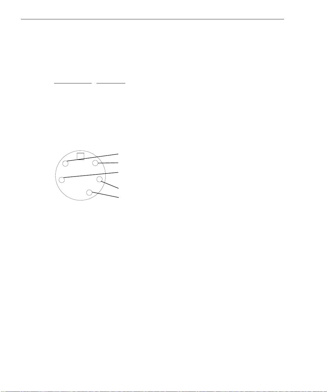
62
Stereo Sync Output Port
The stereo sync output port provides connection to the LCD shutter glasses’ emitter module.
The following table provides the pin connections for the stereo sync output port.
Signal Name
Pin
Ground 1
Ground 2
+12V 3
Stereo Sync 4
No Connect 5
The stereo port is female, 5-pin, mini-DIN as shown in the following figure.
5
4
3
2
1
Page 75

Index
63
A
About this document, ix
Advanced texture processor
hardware
description, 36
Alpha buffer (Z13, Z25, and V25)
description, 39
Antialiased vector support
description, 35
Antistatic precaution, 7, 21
C
Cautions, iii
Changing
default video display driver, 7
Clock sync cable, 12, 28, 40
installing, 14, 26, 28
Configuring
display properties, 4
Connection
deskside
dual-screen, 16, 17, 29
single-screen, 16, 29
desktop
dual-screen, 15
single-screen, 15, 28
Vertex data bus
deskside, 25, 28
desktop, 25
VGA loopback, 19
video cables, 15, 28
Cooling system (Z25 and V25), 57
D
Default video display driver
changing, 7
Defective unit
determining, 19, 32
Deskside
clock sync cable
installing, 26, 28
dual-screen
connection, 29
PCI slots, 13, 16, 17, 26, 27,
29
single-screen
connection, 29
Vertex data bus
installing, 28
removal, 25
Desktop
clock sync cable
installing, 14
PCI slots, 13, 15, 26, 28
single-screen
connection, 28
Vertex data bus
removal, 25
Diagnostics, 18, 31
Digital signal processors (DSP)
description, 56
Digital-to-analog converter
description, 54
DIMM Texture Memory board, 53
DOC compliance, iii
Document
about, ix
conventions, x
Documentation, x
Dual-screen
upgrade
installing, 12, 26
F
FAXLink, xii
Page 76

64
FCC compliance, iii
Frame Buffer, 37, 42
alpha buffer (Z13, Z25, and
V25), 39
gamma correction, 39
Genlock support for dual
monitors, 40
hardware cursor, 39
high-resolution Z buffer, 38
high-speed screen refresh, 40
multiple video lookup tables,
39
multiple video resolutions, 39
stencil buffer (Z13, Z25, and
V25), 38
stereoscopic viewing, 39
true-color image buffer, 38
video plane sets, 37
84/90 bits per pixel, 37
window-mode double
buffering, 39
G
Gamma correction
description, 39
Genlock support for dual monitors
description, 40
Geometry Accelerator, 55
block diagram, 46
board, 55
board installation
deskside, 25, 26
desktop, 25, 26
components, 55
DSPs, 56
I/O FIFO, 55
PCIDMA, 55
Sequence Controller, 56
features and functions, 45
high-speed graphics DMA
engine, 45
MIMD DSP architecture,
45
sequence controller, 45
industry standard PCI bus, 45
support, 58
technical description, 45
Getting started, 1
changing default video display
driver, 7
configuring display properties,
4
RealiZm
configurations, 2
features and functions, 1
graphics accelerators, 1
RenderGL Run-Time Library,
4
starting Windows NT, 3
Gouraud shading support
description, 35
Graphics acceleration processing
block diagram, 41
Graphics Engine, 35
antialiased vector support, 35
Gouraud shading support, 35
high-level vertex interface, 35
sub-pixel accuracy, 36
symbolized vector support, 35
window clipping (Z13, Z25,
and V25), 36
Graphics Engine and Texture
Processor
description, 50
pixel interpolation, 51
request handler, 51
slope calculation, 51
span generation, 51
texture processor, 51
H
Hardware cursor
Page 77

description, 39
Hardware description, 47
Geometry Accelerator, 55
digital signal processors
(DSPs), 56
I/O FIFO, 55
PCIDMA, 55
sequence controller, 56
Rasterization Accelerator, 47
digital-to-analog
converter, 54
Graphics Engine and
Texture Processor, 50
PCIDMA, 50
resolver architecture, 53
video memory, 54
video selector and mapper,
54
Z10, 47
Z13, 48
Z25 and V25, 49
Texture memory, 53
Z10 Texturing Accelerator, 52
High-level vertex interface
description, 35
High-resolution Z buffer
description, 38
High-speed
DMA engine
description, 34
graphics DMA engine
description, 45
screen refresh
description, 40
I
I/O FIFO
description, 55
Industry standard PCI bus
description, 45
65
Installing
clock sync cable, 12, 14, 26,
28
dual-screen upgrade
Z10, 12
Z13, Z25, or V25, 26
texture memory, 22
texturing accelerator, 8
Vertex data bus, 28
video display driver, 17, 30
Z13, Z25, or Geometry
Accelerator, 24
Interfaces, 60
Geometry Accelerator (Z13,
Z25, and V25)
description, 35
stereo sync output port, 62
VGA input port, 61
video output port, 60
Intergraph
bulletin board service, xi
FAXLink, xii
Internet, xii
Internet, xii
L
Last known good, 19, 31
M
MIMD DSP architecture
description, 45
MIP-mapping support with trilinear
interpolation
description, 37
Monitor resolutions, 59
Multiple video
lookup tables
description, 39
resolutions
description, 39
O
Operating system
Page 78

66
information, x
P
Packing list
dual-screen option
verifying, 12, 26
PCI bus interface
description, 34
high-speed DMA engine, 34
interface for Geometry
Accelerator (Z13, Z25, and
V25), 35
PCI-compatible bus interface,
34
PCI slots
deskside, 13, 16, 17, 26, 27, 29
desktop, 13, 15, 26, 28
PCI-compatible bus interface
description, 34
PCIDMA
description, 50, 55
Pinouts
stereo sync output port, 62
VGA input port, 61
video output port, 60
Pixel interpolation
description, 51
Pixelization Accelerator, 41
Port
stereo sync output, 62
VGA input, 61
video output, 60
Precautions, 7, 21
R
Rasterization Accelerator
components, 47
features, 33
functions, 40
technical description, 33
Z10, 47
block diagram, 43
board, 47
Z13, 48
back view, 48
front view, 48
Z13, Z25, and V25
block diagram, 44
Z25 and V25, 49
back view, 50
front view, 49
RealiZm
configurations, 2
features and functions, 1
graphics accelerators, 1
Removing
clock sync cable, 25
Vertex data bus, 25
RenderGL Run-Time Library
getting started, 4
Replacing
Z10 or Z10-T, 10
Z13, Z25, or Geometry
Accelerator, 24
Z13, Z25, V25 or Geometry
Accelerator, 24
Request handler
description, 51
Resolver architecture
description, 53
S
Selecting
last known good, 19, 31
VGA mode, 19, 32
Sequence controller
description, 45, 56
Slope calculation
description, 51
Span generation
description, 51
Page 79

67
Specifications, 57
cooling system (Z25 and V25),
57
Geometry Accelerator support,
58
interfaces, 60
monitor resolutions, 59
InterVue-27, 59
multi-sync, 59
RealiZm graphics accelerators,
57
texturing system, 58
Stencil buffer (Z13, Z25, and V25)
description, 38
Stereo sync output port, 62
Stereoscopic viewing
description, 39
Sub-pixel accuracy
description, 36
Support
bulletin board service, xi
FAXLink, xii
Internet, xii
telephone, xi
Symbolized vector support
description, 35
System
powering on, 3
T
Technical description, 33
Geometry Accelerator features
and functions, 45
high-speed graphics DMA
engine, 45
MIMD DSP architecture,
45
sequence controller, 45
Rasterization Accelerator
features, 33
Frame Buffer, 37
Graphics Engine, 35
PCI bus interface, 34
Texture Processor, 36
Rasterization Accelerator
functions, 40
Frame Buffer, 42
Pixelization Accelerator,
41
Texture Processor, 42
Telephone support, xi
Texture memory
description, 36, 53
installing, 22
socket
V25, 23
Z13, 22
Z25, 23
Texture Processor, 36, 42
advanced texture processor
hardware, 36
description, 51
MIP-mapping support with
trilinear interpolation, 37
texture memory, 36
Texturing accelerator
installing, 8
Z10, 52
Texturing system, 58
Training, x
Troubleshooting, 18, 31
True-color image buffer
description, 38
U
Upgrading or replacing
Z10, 7
Z13, Z25, V25, 21
Usable video resolution, 19, 31
V
Vertex data bus
deskside, 25, 28
desktop, 25
installing, 28
removal, 25
Page 80

68
VGA
connection
loopback cable, 19
mode, 19, 32
VGA input port, 61
pinouts, 61
Video
cables
connecting, 15, 28
display
properties, 4
troubleshooting, 18, 31
display driver
installing, 17, 30
memory
description, 54
planes
description, 37
random access memory
(VRAM), 54
resolution
usable, 19, 31
selector and mapper
(VSM)(Z10 Only)
description, 54
Video output port, 60
pinouts, 60
W
Warnings, iii
Window clipping (Z13, Z25, and
V25)
description, 36
Window-mode double-buffering
description, 39
Windows NT
starting, 3
Windows NT Workstation
information, x
Z
Z10 Texturing Accelerator
board, 52
Page 81

Returned Goods Authorization (RGA) Form
Date Returned Base Serial No.
(On white bar code ID plate on back of base unit)
RGA No.
From Customer Name
Customer Contact Phone
Mail Address
Reason for Return
(From Intergraph Customer Response Center)
NOTE All returned equipment MUST be shipped in original Intergraph packaging to obtain warranty
service.
WARNING Back up disk drives before returning equipment. Intergraph is not responsible for data
lost in shipping or repair process.
Page 82

Warranty Procedure
Some malfunctioning equipment cannot be repaired in the field, and you must return it to Intergraph for
repair. Follow these steps to obtain a Returned Goods Authorization (RGA) log number and return the
malfunctioning equipment.
1. Determine the serial number of the system. The serial number is located on the white bar code
identification label on the back of the base unit.
2. Call the Intergraph Customer Response Center at 1-800-633-7248, and identify your call to the
operator as a Warranty Call. After giving the operator the serial number of the system, you will be
assigned a RGA log number.
3. Complete the RGA Form on the previous page, entering the RGA log number obtained from the
Customer Response Center. Ensure that the address in the From section is the location to which you
want the equipment to be returned.
4. Place the RGA form in the box containing the equipment. This form must accompany returned
equipment.
5. Secure a Repair Depot address label from the next page to the box containing the equipment.
6. Ship the box containing the equipment to Intergraph.
When the service activity has been completed by Intergraph, the repaired or replaced equipment will be
shipped to the address listed on the RGA Form.
NOTE Parts damaged during shipping and parts not covered by the warranty are liable for repair
charges.
Page 83

TO Repair Depot RGA No. ________________________
Intergraph Corporation
9805 Kellner Road
Huntsville AL 35894
TO Repair Depot RGA No. ________________________
Intergraph Corporation
9805 Kellner Road
Huntsville AL 35894
TO Repair Depot RGA No. ________________________
Intergraph Corporation
9805 Kellner Road
Huntsville AL 35894
Page 84

 Loading...