

Page 1

RAX Systems
System Reference
January 1999
DHA034800
Page 2

Copyright
1999 Intergraph Computer Systems. All rights reserved. This document contains information protected by copyright, trade secret, and
trademark law. This document may not, in whole or in part, be reproduced in any form or by any means, or be used to make any derivative
work, without written consent from Intergraph Computer Systems.
Use, duplication, or disclosure by the United States Government is subject to restrictions as set forth in subdivision (c)(1)(ii) of the rights in
technical data and computer software clause at DFARS 252.227-7013. Unpublished rights are reserved under the copyright laws of the
United States.
Intergraph Computer Systems, Huntsville AL 35894-0001
Notice
Information in this document is subject to change without notice and should not be considered a commitment by Intergraph Computer
Systems. Intergraph Computer Systems shall not be liable for technical or editorial errors in, or omissions from, this document. Intergraph
Computer Systems shall not be liable for incidental or consequential damages resulting from the furnishing or use of this document.
All warranties given by Intergraph Computer Systems about equipment or software are set forth in your purchase contract. Nothing stated in,
or implied by, this document or its contents shall be considered or deemed a modification or amendment of such warranties.
Trademarks
Intergraph Computer Systems and the Intergraph Computer Systems logo are registered trademarks of Intergraph Computer Systems.
StudioZ, RenderRAX, and ViZ RAX are trademarks of Intergraph Computer Systems. Other brands and product names are trademarks of
their respective owners.
FCC/DOC Compliance
This equipment has been tested and found to comply with the limits for a Class B digital device, pursuant to part 15 of the FCC Rules. These
limits are designed to provide reasonable protection against harmful interference when the equipment is operated in a commercial
environment. This equipment generates, uses, and can radiate radio frequency energy. If the equipment is not installed and used in
accordance with the instruction manual, it may cause harmful interference to radio communications.
Operation of this equipment in a residential area is likely to cause harmful interference in which case the user will be required to correct the
interference at his own expense.
Changes or modifications made to the system that are not approved by the party responsible for compliance could void the user’s authority to
operate the equipment.
This Class B digital apparatus meets all requirements of the Canadian Interference-Causing Equipment Regulations. Cet appareil numérique
de la classe B respecte toutes les exigencies du Règlement sur le materiél brouilleur du Canada.
Warnings
The service and upgrade instructions should be performed by qualified personnel only. Qualified personnel do not have to be Intergraph
service personnel. Qualified personnal can include those who are familiar with servicing computers, can follow instructions in a manual to
service equipment, and can do so without harm to themselves or damage to the equipment.
Changes or modifications made to the system that are not approved by the party responsible for compliance could void the user's authority to
operate the equipment.
To reduce the risk of electrical shock, do not attempt to open the equipment unless instructed. Do not use a tool for purposes other than
instructed.
There is a danger of explosion if the battery is incorrectly replaced. Replace the battery only with the same or equivalent type as
recommended by the manufacturer. Dispose of used batteries according to the manufacturer's instructions.
Notes
Read all operating instructions before using this device. Keep these instructions for future reference. Follow all warnings on the device or in
the operating instructions. This device is designed and manufactured to comply with approved safety standards for information processing
and business equipment.
Page 3

Contents
Preface...............................................................................................................................v
About This Document ........................................................................................................ v
Document Conventions...................................................................................................... v
Customer Support.............................................................................................................. vi
1 Accessing the Components........................................................................................... 1
Before You Begin............................................................................................................... 2
Tools................................................................................................................................... 2
Avoiding Electrostatic Discharge....................................................................................... 2
Opening the Base Unit........................................................................................................ 3
Opening and Closing the Face Panel.................................................................................. 3
Closing the Base Unit.........................................................................................................4
System Illustrations............................................................................................................5
iii
Hardware and Software Support Services........................................................... vi
World Wide Web................................................................................................ vi
Intergraph Bulletin Board Service....................................................................... vi
FAXLink............................................................................................................vii
Telephone........................................................................................................... vii
More Support Options....................................................................................... viii
2 Servicing the System ....................................................................................................7
Before You Begin............................................................................................................... 8
Base Unit Components....................................................................................................... 8
Disk Drives......................................................................................................................... 9
System Disk Drive............................................................................................... 9
CD-ROM Drive.................................................................................................. 10
Floppy Disk Drive.............................................................................................. 12
Disk Drives in the Disk Drive Bay..................................................................... 13
Disk Drive Bay.................................................................................................................14
SAF-TE Card....................................................................................................................16
Power Supply ................................................................................................................... 17
Processor Modules ........................................................................................................... 19
Heat-Sink Mounting Brackets.......................................................................................... 20
Retention Modules ........................................................................................................... 20
Dual Inline Memory Modules .......................................................................................... 21
System Board ................................................................................................................... 22
Expansion Cards............................................................................................................... 23
Chassis Fan....................................................................................................................... 24
Disk Drive Bay Fans ........................................................................................................ 25
Lithium (CMOS/Clock) Battery....................................................................................... 26
LEDs, Power, and Reset Switches.................................................................................... 27
Page 4

iv
3 Upgrading the System................................................................................................ 29
Before You Begin............................................................................................................. 30
Adding Memory...............................................................................................................30
Upgrading Processors.......................................................................................................32
Adding Expansion Cards.................................................................................................. 32
Slot Locations .................................................................................................... 33
Installing Expansion Cards................................................................................. 33
Assigning System Resources..............................................................................34
Adding Disk Drives to the Disk Drive Bay...................................................................... 34
Adding an Internal Peripheral Device .............................................................................. 35
Adding External SCSI Peripheral Devices....................................................................... 37
SCSI Cable Length Guidelines...........................................................................38
SCSI Cable Quality Guidelines..........................................................................38
SCSI ID Guidelines............................................................................................ 38
SCSI Termination Guidelines for External Devices........................................... 39
Connecting an External SCSI Drive................................................................... 39
Changing SCSI Host Adapter or Device Settings .............................................. 40
4 System Hardware....................................................................................................... 41
Hardware Overview..........................................................................................................42
Functional Diagram.......................................................................................................... 43
System Board ................................................................................................................... 44
Disk Drive Bay.................................................................................................................44
Cable Routing and Pinouts.................................................................................44
Jumper Settings.................................................................................................. 46
Disk Drive LEDs................................................................................................ 46
Power Supply ................................................................................................................... 47
Chassis Cooling Fans ....................................................................................................... 48
Disk Drive Bay Cooling Fans........................................................................................... 49
Hardware Monitoring....................................................................................................... 49
5 Peripheral Devices....................................................................................................... 51
Internal Peripheral Device Cables....................................................................................52
Floppy Disk Drive Cable ................................................................................... 52
EIDE Cable........................................................................................................ 52
Disk Drive Bay SCSI Cable............................................................................... 53
Ultra Wide SCSI Cable...................................................................................... 53
Peripheral Device Configuration...................................................................................... 53
Floppy Disk Drive.............................................................................................. 54
IDE CD-ROM Drive.......................................................................................... 54
SCSI Disk Drives............................................................................................... 55
6 System Information.................................................................................................... 57
Specifications................................................................................................................... 58
System Configuration Summary.......................................................................................58
System Board Components .............................................................................................. 59
Page 5

Preface
This System Reference document describes how to service and upgrade your Intergraph
Computer Systems rack-mount RAX System. This document supports the following RAX
systems:
u
StudioZ RenderRAX III
u
ViZ RAX
About This Document
This System Reference document is organized as follows:
u
Chapter 1, “Accessing the Components,” describes how to open and close the base unit
and how to access internal system components.
u
Chapter 2, “Servicing the System,” describes how to replace standard system components.
u
Chapter 3, “Upgrading the System,” describes how to add components to the system.
u
Chapter 4, “System Hardware,” provides a system hardware overview and technical
information on system components.
v
u
Chapter 5, “Peripheral Devices,” provides information on cabling and configuration of
standard system peripherals.
u
Chapter 6, “System Information,” provides system specifications and other general
technical information.
Document Conventions
Bold
Italic Variable values that you supply, or cross-references.
Monospace
SMALL CAPS Key names on the keyboard (such as D, ALT, or F3) and names of files and
CTRL+D Press a key while simultaneously pressing another key; for example, press
Commands, words, or characters that you key in literally.
Output displayed on the screen.
directories. You can type filenames and directory names in the dialog boxes
or the command line in lowercase unless directed otherwise.
CTRL and D simultaneously.
Page 6

vi
Customer Support
Intergraph Computer Systems offers an assortment of customer support options.
Hardware and Softwa r e Suppor t Services
Intergraph Computer Systems provides a variety of hardware services for Intergraph and thirdparty equipment. Services include warranty upgrades, repair depot service, on-site hardware
maintenance, system administration, and network consulting. Hardware purchased from
Intergraph Computer Systems includes a factory warranty ranging from 30 days to three years.
A detailed warranty description is available on the World Wide Web; see the Support pages at
http://www.intergraph.com/ics.
Intergraph Computer Systems provides complimentary software support for 30 or 90 days
following shipment of a hardware or software product. This includes World Wide Web
access, Intergraph Bulletin Board Service access, FAXLink service, and telephone (Help
Desk) support. At the end of the complimentary support period, you can purchase other levels
of software support.
World Wide Web
You can visit Intergraph Computer Systems on the World Wide Web at
http://www.intergraph.com/ics. On these pages, you can get news and product information,
technical support information, software updates and fixes, and more.
Intergraph Bulletin Board Servi ce
On the Intergraph Bulletin Board Service (IBBS), you can get technical support information,
software updates and fixes, and more.
NOTE Most of the system software for your RAX system can be found in the TDZ 2000 GL2 Series A
area of the IBBS. Additional software can be found in the Digital Media area of the IBBS.
To connect to the IBBS:
1. Set your system’s communications protocol for eight (8) data bits, no parity, one (1) stop
bit, and any baud rate up to 14,400.
2. Using a modem, call 1-256-730-8786. Outside the United States, call one of the mirror
sites listed on World Wide Web; see the Software Support pages at
http://www.intergraph.com.
3. At the login prompt, key in your user ID, or new if you have not used the IBBS before.
4. Follow the menus to find what you need.
Page 7

If you have trouble connecting to or using the IBBS, call the Customer Response Center at
1-800-633-7248 (product entry IBBS) or leave a message for the IBBS System Operator at
1-256-730-1413.
FAXLink
To use the FAXLink:
u
u
Telephone
To get customer support by telephone:
u
u
Have the following information available when you call:
vii
Call 1-800-240-4300 for information on how to get technical support information.
Call 1-256-730-9000 to get documents (up to five per call).
In the United States, call 1-800-633-7248 between the hours of 7:00 a.m. and 7:00 p.m.
Central Time, Monday through Friday (except holidays).
Outside the United States, contact your local Intergraph Computer Systems subsidiary or
distributor.
u
Your service number, which identifies your site to Intergraph Computer Systems. You
use your service number for warranty or maintenance calls.
u
Your Customer Personal Identification Number (CPIN). You get a CPIN the first time
you call the Customer Response Center; it is associated with your service number for
future call logging.
u
The product’s name or model number.
u
The product’s serial number. Software product serial numbers are included in the product
packaging. Hardware product serial numbers are on a sticker affixed to the product.
u
Your name and telephone number.
u
A brief description of the question or problem.
Page 8

viii
More Support Options
To get information on more customer support options:
u
Visit the Support pages on the World Wide Web at http://www.intergraph.com/ics.
u
For hardware support questions in the United States, call 1-800-763-0242.
u
For software support questions in the United States, call 1-800-345-4856.
Outside the United States, contact your local Intergraph Computer Systems subsidiary or
distributor.
Page 9

1 Accessing the Components
This chapter describes how to access the internal components of the system so you can service
and upgrade your RAX system. This chapter also lists tools and describes methods for
avoiding electrostatic discharge, removing and replacing cover panels, and accessing
components.
Before You Begin...................................................................................................................... 2
Tools.......................................................................................................................................... 2
Avoiding Electrostatic Discharge.............................................................................................. 2
Opening the Base Unit...............................................................................................................3
Opening and Closing the Face Panel......................................................................................... 3
Closing the Base Unit................................................................................................................ 4
System Illustrations................................................................................................................... 5
1
Page 10
2
Before You Begin
WARNING Disconnect the system and peripheral devices from AC power before servicing internal
components! Failure to remove AC power may result in equipment damage or personal
injury.
WARNING Follow all warnings and cautions in the servicing instructions. If you fail to follow
documented procedures, personal injury and damage to equipment can result.
CAUTION Use an antistatic wrist strap for all servicing procedures to avoid the possibility of electrostatic
discharge.
“Right side” and “left side” are as seen from the front of the unit.
Tools
You will need the following tools to service the system:
u
Antistatic wrist strap
u
Quarter-inch nutdriver
u
No. 1 and No. 2 Phillips screwdrivers
u
Three-sixteenth-inch or 5 mm nutdriver
u
Five-sixteenth-inch or 8 mm nutdriver
u
Small single-slot screwdriver
Avoiding Electrostatic Discharge
Sensitive components inside the base unit can be damaged by static electricity. To protect
against this possibility, take the following precautions when working with internal
components.
u
Unplug the unit from AC power before servicing any electronic component inside the
chassis.
u
Touch the bare metal of the base unit to ensure the base unit and your body are at the
same electric potential.
u
Handle all printed circuit boards as little as possible and by the edges only. Leave new
parts in their protective packaging until you install them.
u
Use a disposable or reusable antistatic wrist strap when servicing or upgrading the system.
Once a disposable wrist strap is used, it cannot be used again.
Page 11

u
Attach an antistatic wrist strap to any bare metal part of the base unit. The metal
conductor in the elastic sleeve of reusable antistatic straps must contact bare skin.
Opening the Base Unit
WARNING Before you open the base unit, shut down the system and turn off power to the system
and external devices (including peripheral devices and the monitor). Use caution to
avoid injury when removing covers and other hardware.
CAUTION Ensure the front and side stabilizers of the rack in which the system is mounted are fully
extended.
To open the base unit:
1. Remove the screws that secure the handles to the rack.
2. Disconnect all cables including the power cable, monitor, and all peripheral cables from
the back of the unit.
3. Slide the base unit out of the rack until it locks in the extended position.
4. Remove and retain the two screws that secure the cover to the chassis: one each on the
upper left and upper right corners of the back of the chassis.
3
5. Slide the cover back about an inch, then lift the cover off.
6. Attach the grounding clip from the antistatic wrist strap to bare metal.
Opening and Closing the Face Panel
To open the face panel:
1. Open the disk drive bay door.
2. Loosen the two thumb screws that secure the face panel to the base unit (on the upper
right and upper left corners of the face plate). See the following figure.
3. Pull the face panel toward you to open it. The face panel swings down on hinges attached
to the lower corners of the base unit. See the following figure.
Page 12
4
Face Panel Thumb Screw
(one on each side)
To close the face panel:
1. Lift the face panel upward and push it onto the base unit.
2. Secure the face panel to the base unit by tightening the two thumb screws.
3. Close the disk drive bay door.
Closing the Base Unit
CAUTION After servicing or upgrading the system, always replace the covers that were removed. The
covers ensure the system maintains proper air flow, so internal components do not overheat
and fail. The covers also ensure that electromagnetic interference (EMI) emissions remain
below the standard requirements.
To close the base unit:
1. Remove the antistatic wrist strap from the base unit.
2. Replace the cover.
3. Secure the cover to the base unit with the screws retained earlier.
4. Slide the base unit into the rack.
5. Secure the base unit to the rack by replacing the screws attaching the handles to the rack.
6. Reconnect all cables including the power cable, monitor, and peripheral cables to the
back of the system.
Page 13
System Illustrations
The following illustrations show both external and internal views of the system.
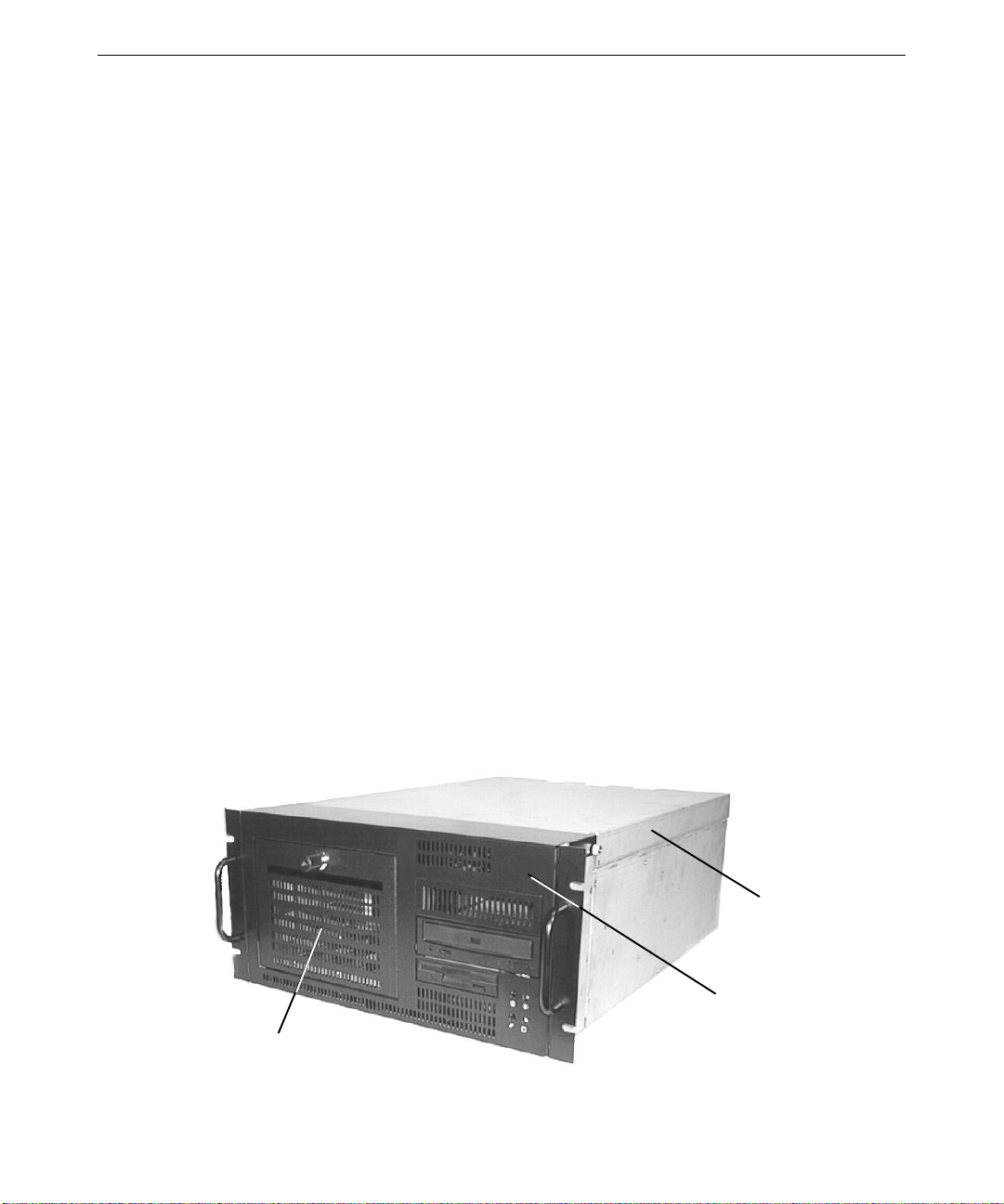
This front, right view shows the system with all covers in place .
Disk Drive Bay
Door Lock
5
Top Cover
Disk Drive Bay
CD-ROM Drive
Floppy Disk Drive
Face Panel
System LEDs and
Power/Reset Switches
Page 14
6
Power Supply
Input/Output Panel
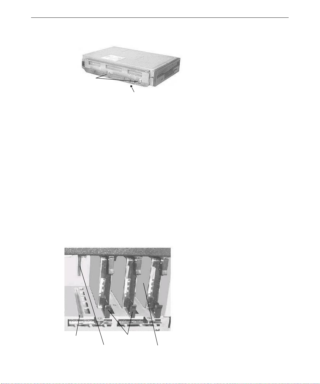
This back, right view shows major internal parts of the system without covers, cables, system
board, and option cards.
Peripheral
Device Bay
Chassis Fan/
Mounting
Plate
Disk Drive Bay
Fans
Face Panel
Disk Drive Bay
Expansion Slots
Page 15

2 Servicing the System
This chapter describes how to replace the standard parts inside your RAX system.
Before You Begin...............................................................................................................8
Base Unit Components....................................................................................................... 8
Disk Drives......................................................................................................................... 9
System Disk Drive............................................................................................... 9
CD-ROM Drive.................................................................................................. 10
Floppy Disk Drive.............................................................................................. 12
Disk Drives in the Disk Drive Bay..................................................................... 13
Disk Drive Bay.................................................................................................................14
SAF-TE Card....................................................................................................................16
Power Supply ................................................................................................................... 17
Processor Modules ........................................................................................................... 19
Heat-Sink Mounting Brackets.......................................................................................... 20
Retention Modules ........................................................................................................... 20
Dual Inline Memory Modules .......................................................................................... 21
System Board ................................................................................................................... 22
Expansion Cards............................................................................................................... 23
Chassis Fan....................................................................................................................... 24
Disk Drive Bay Fans ........................................................................................................ 25
Lithium (CMOS/Clock) Battery....................................................................................... 26
LEDs, Power, and Reset Switches.................................................................................... 27
7
Page 16
8
Before You Begin
WARNING Disconnect the system and peripheral devices from AC power before servicing internal
components! Failure to remove AC power may result in equipment damage or personal
injury.
WARNING There is a danger of explosion if the battery is incorrectly replaced.
WARNING Follow all warnings and cautions in the servicing instructions. If you fail to follow
documented procedures, personal injury and damage to equipment can result.
CAUTION Use an antistatic wrist strap for all servicing procedures to avoid the possibility of electrostatic
discharge.
CAUTION Do not overtighten screws and other fasteners to avoid damaging threads.
CAUTION Follow all warnings and cautions in these servicing instructions. If you fail to follow
documented, approved procedures, personal injury or damage to equipment can result.
See Chapter 1, “Accessing the Components,” for details on opening the system and protecting
against electrostatic discharge. These procedures assume you have removed the cover from
the system. “Right side” and “left side” are as seen from the front of the unit. After servicing
the system, replace panels as described in Chapter 1, “Accessing the Components.”
Base Unit Components
The following figure shows the base unit components that can be replaced:
Disk Drive
Bay Door
Top Cover
Face Panel
Page 17

To replace the disk drive bay door, you must first remove the top cover and open the face
panel. To replace the face panel, you must remove the top cover and the disk drive bay door.
To replace the top cover:
1. Remove the top cover. See Chapter 1, “Accessing the Components,” for details.
2. Install the new cover.
To replace the disk drive bay door:
1. Open the face panel. See Chapter 1, “Accessing the Components,” for details.
2. Remove the two hinge screws attaching the door to the face panel.
3. Remove the door.
4. Position the new door so that the screw holes on the door are aligned with holes in the
face panel.
5. Replace the two hinge screws, ensuring that the hinge screws are equally tightened. This
will ensure that the door is centered properly.
To replace the face panel:
1. Remove the disk drive bay door from the old face panel. See the previous procedure.
9
2. Install the disk drive bay door in the new face panel. See the previous procedure.
3. Remove the old face panel by removing the two shoulder screws at the bottom left and
right corners of the face panel.
4. Align the bottom of the new face panel with the front of the unit, and reattach the two
shoulder screws from step 3.
5. Close the new face panel. See Chapter 1, “Accessing the Components,” for details.
Disk Drives
This section explains how to replace the CD-ROM drive and the various disk drives in the
system. See Chapter 5, “Peripherals,” for details on drive configuration and cables.
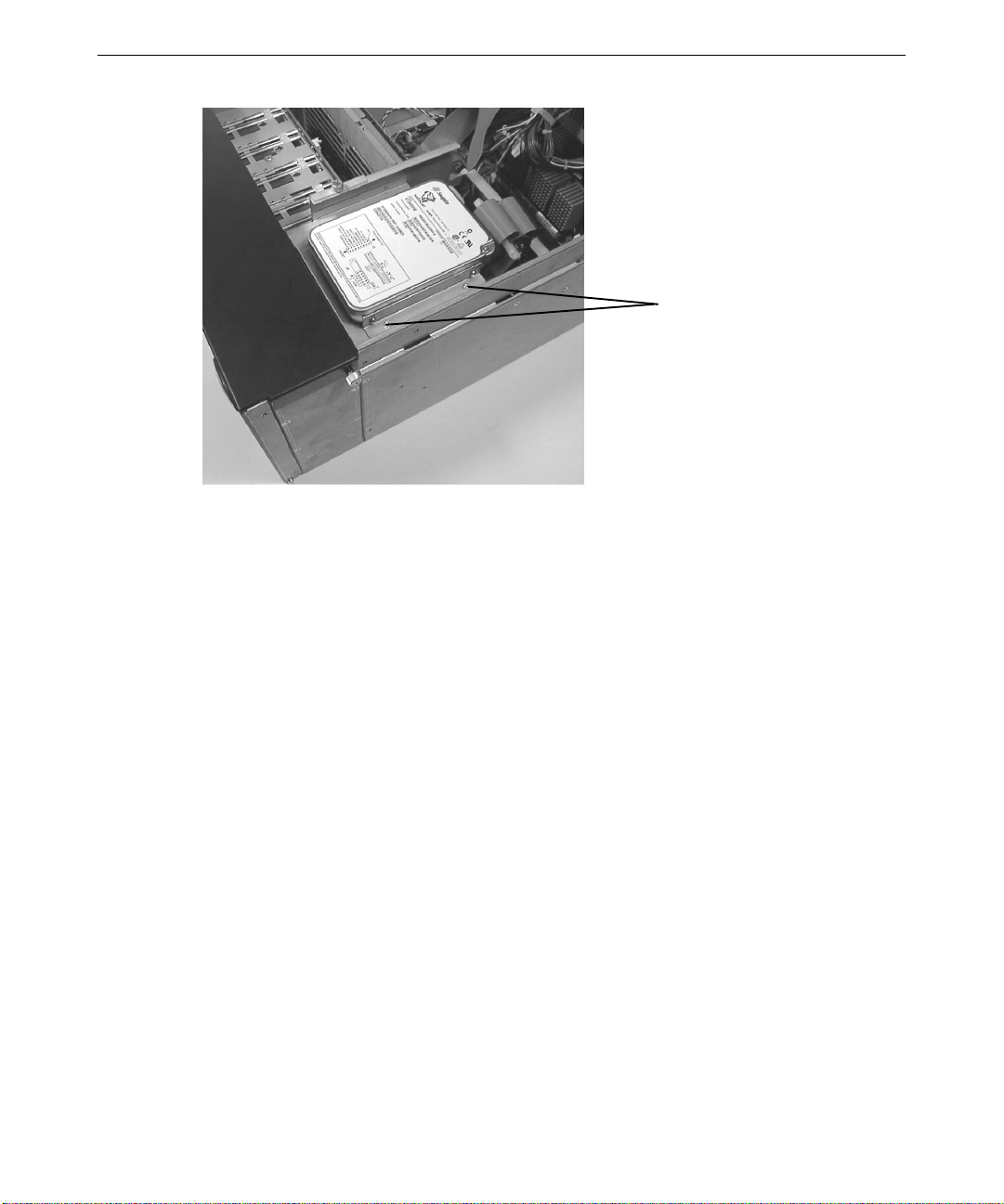
System Disk Drive
The system disk drive is located in the uppermost part of the peripheral device bay, above the
CD-ROM and floppy disk drives.
Page 18
10
Nuts (two on each side)
To replace the system disk drive:
1. Disconnect the power cable and SCSI cable from the disk drive.
2. Remove the four nuts (two on each side) from the vertical screws on each side of the disk
drive, and lift the disk drive out of the chassis.
3. Remove the brackets from the replaced disk drive and secure them to the new disk drive.
WARNING Handle the disk drive carefully to prevent failure and voiding the warranty for the drive.
4. Replace the new disk drive in the chassis and secure it with the four nuts removed
previously.
5. Connect the power cable and SCSI cable to the disk drive.
You will need to reinstall the operating system and associated system software on the new
system disk drive. See the System Setup document delivered with the system for more
information.
CD-ROM Drive
The procedure for replacing a SCSI or an EIDE CD-ROM drive is the same, except for data
cables and jumper settings.
To replace the CD-ROM drive:
1. For ease of access, remove the chassis fan as described later in “Chassis Fan.”
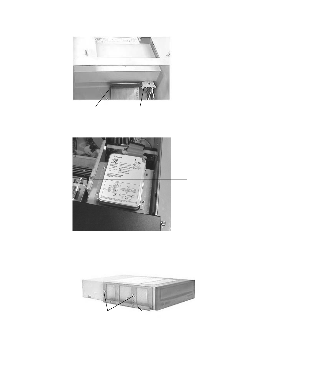
2. Disconnect the power cable and data cable from the CD-ROM drive. Note the position of
the red stripe on the data cable. See the following figure.
Page 19
11
Data Cable Power Connector
3. Loosen the thumb screw on the front-most locking plate on the top left side of the
peripheral device bay.
Locking Plate
Thumb Screw
4. Lift and hold the locking plate.
5. From inside the chassis, push the back of the CD-ROM until the bezel clears the front of
the chassis, then slide the device out.
6. Remove the mounting guides from the right and left sides of the CD-ROM drive.
Mounting Guide
Screws
Slot for Drive
Placement
7. Note the jumper settings on the back of the CD-ROM drive.
Page 20
12
8. Do one of the following on the new CD-ROM drive:
−
Set the EIDE master/slave jumper to the same position (Master) as the old drive if
you are replacing an EIDE drive.
−
Set the SCSI ID jumper to the same address as the old drive if you are replacing a
SCSI drive.
9. Install the mounting guides on the sides of the new CD-ROM drive. The flat mounting
guide goes on the right side of the CD-ROM drive; the slotted mounting guide goes on the
left side.
10. Slide the new CD-ROM drive into the chassis and align the first slot in the mounting
guide with the locking plate.
11. Lower the locking plate, making sure the locking plate tabs slide into the first slot on the
mounting guide.
12. Tighten the locking plate thumb screw.
13. Connect the data cable and power cable to the CD-ROM drive.
14. Replace the chassis fan, as described later in “Chassis Fan.”
Floppy Disk Drive
To replace the floppy disk drive:
1. For ease of access, remove the chassis fan as described later in “Chassis Fan.”
2. Remove the CD-ROM drive as described previously in “CD-ROM Drive.”
3. Disconnect the power cable and data cable from the drive. Note the position of the red
stripe on the data cable.
Data
Cable
Power
Connector
4. Loosen the thumb screw on the locking plate to the top left side of the peripheral device
bay, as described previously in “CD-ROM Drive.”
5. Lift and hold the locking plate.
6. From inside the chassis, push the back of the floppy disk drive until the bezel clears the
front of the chassis, and slide the device out.
Page 21
7. Remove the mounting guide on the left side of the floppy disk drive.
Mounting
Guide
Screws
Alignment Slot
8. Attach the mounting guide to the left side of the new floppy disk drive.
9. Raise the locking tab on the peripheral drive bay.
10. Slide the new floppy disk drive into the chassis and align the first slot on the mounting
guide with the locking plate tab.
11. Lower the locking plate, making sure the locking plate tab slides into the first slot on the
mounting guide.
12. Connect the data cable and power cable to the floppy disk drive.
13. Replace the CD-ROM drive as described previously in “CD-ROM Drive.”
14. Tighten the locking plate thumb screw.
13
15. Replace the chassis fan, as described later in “Chassis Fan.”
Disk Drives in the Disk Drive Bay
The disk drive bay may contain up to four JBOD (for “just a bunch of disks”) or RAID disk
drives, depending on the configuration of your system. The replacement procedure for these
drives is similar.
Drive Rail
Drive Connector
Latching Clips
Drive 0
Page 22

14
To replace a disk drive in the disk drive bay:
1. Open the disk drive bay door on the front of the system.
2. Flip the drive’s latching clips outward to disengage the disk drive. Wait 30 seconds to
allow the drive to spin down and park the heads.
3. Carefully eject the drive completely from the rails, and remove it from the disk drive bay.
WARNING Handling a spinning disk drive or mishandling a removed disk drive can cause the
heads to crash! Subsequent failures may not be noticeable for three to six months.
Handle disk drives carefully to avoid damage.
4. Remove the drive mounting plate from the removed disk drive, making sure to retain the
mounting plate screws. Attach the mounting plate to the bottom (circuit board side) of the
new drive, using the four screws you retained from the removed drive.
WARNING Removing and attaching the drive mounting plate requires careful handling to avoid
contact with the delicate, electrostatic-sensitive parts on the circuit board of the disk
drive. Handle disk drives carefully to prevent failure and voiding the warranty for the
drives.
5. To insert the new drive, extend the latching clips on the drive and align the rails on the
sides of the drive with the slot guides in the disk drive bay. The metal casing of the drive
faces left.
6. With your thumb, push the mounting plate at the center between the latching clips until it
slides all the way into the slot and firmly engages the connector.
7. Close the latching clips to lock the drive in the slot.
8. If the system has a RAID configuration, verify that the drive status LED lights. Its
behavior is dependent on the status of the array that the drive is in.
9. Label the new drive with the same ADP, CH, and ID numbers used on the replaced drive,
as appropriate.
Disk Drive Bay
The disk drive bay includes the disk drive cage, backplane, and LEDs. This assembly is
always replaced as one unit.
To replace the disk drive bay:
1. Remove all the drives from the slots in the disk drive bay as described previously in “Disk
Drives in the Disk Drive Bay.” Note the original slot location for each drive. The drives
should be reinstalled in the same slot locations from which they were removed.
Page 23

2. Remove and retain the six screws that attach the disk drive bay to the chassis. Support
the disk drive bay as the last screw is removed.
15
Disk Drive Section Screws
3. Gently pull forward on the disk drive bay until it is partially out of the chassis.
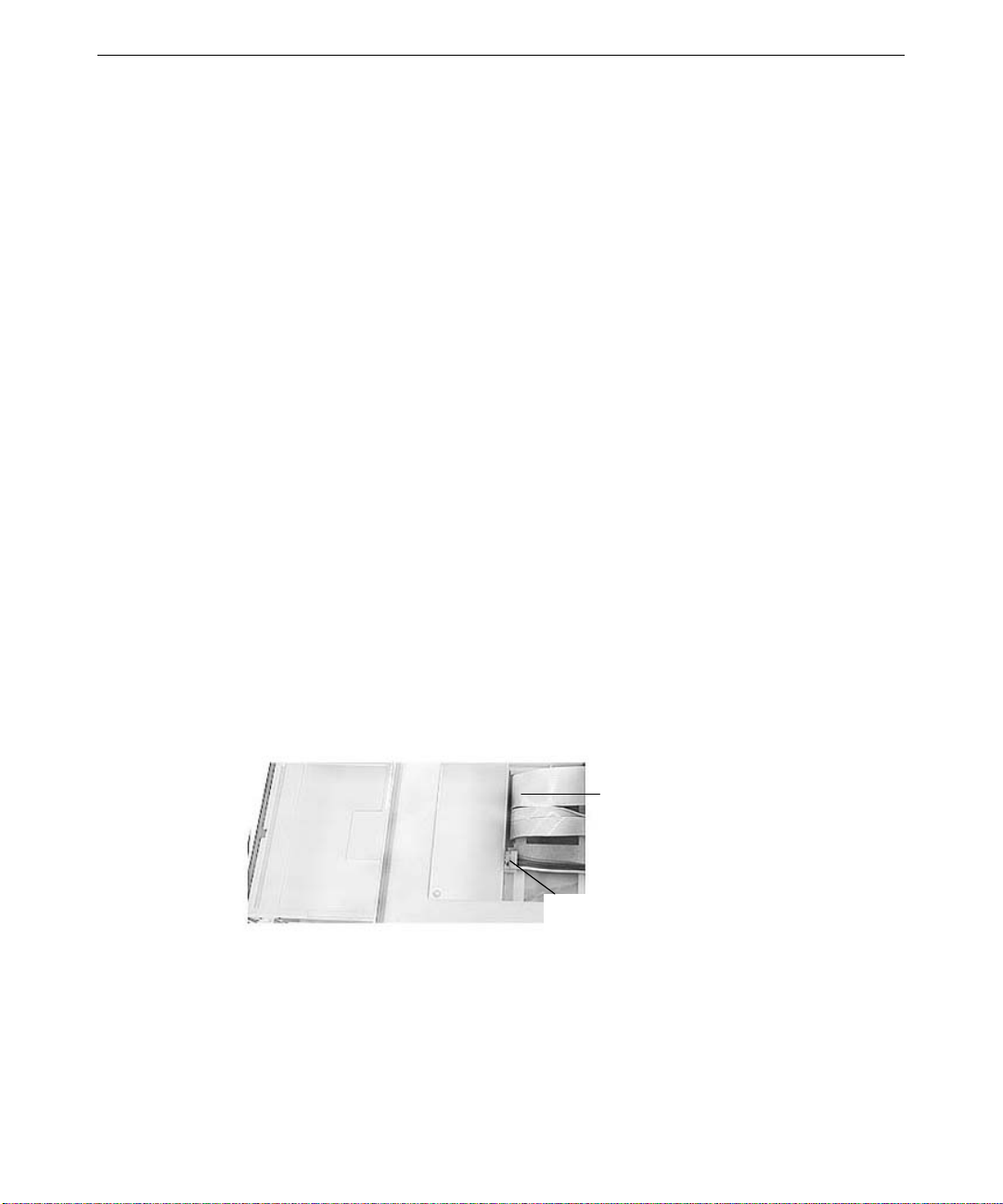
4. Note the location of the SCSI cable and disconnect the SCSI cable from the back of the
disk drive bay.
Power
Connectors
SCSI Cable
5. Disconnect the power cables attached to the disk drive bay, using caution to avoid
damage to the cables and components on the disk drive backplane. Do not pull on the
wires of the power cables to remove them from the plugs, as damage to the cables will
occur.
6. Slide the disk drive bay the rest of the way out of the chassis.
7. Verify that the jumper settings on the back of the replacement disk drive bay match the
one being replaced.
Page 24

16
NOTE If the system uses the optional Mylex RAID controller, the jumper connectors JP2 and JP3
must not have any jumpers installed.
9. If the old disk drive bay has a SAF-TE card (as described in the next section), remove it
from the old disk drive bay and install it in the same location on the new disk drive bay.
10. Insert the new disk drive bay partially into the chassis.
11. Reconnect the SCSI cable and power connectors in the same positions as the old disk
drive bay.
12. Insert the new disk drive bay the rest of the way into the chassis, and secure it with the
screws removed earlier.
13. Insert the disk drives into the slots in the disk drive bay. The drives should be installed in
the same slots from which they were removed.
14. Replace the front panel and cover.
15. Restart the system and ensure the LED for each drive lights and remains steady green. If
not, refer to the System Setup for status LED information.
SAF-TE Card
The SCSI Activity Fault-Tolerant Enclosure (SAF-TE) card is an option used only on systems
with RAID configurations. If your system has a RAID configuration with a SAF-TE card, use
the following procedure to replace the SAF-TE card.
To move or replace the SAF-TE card:
1. Remove the disk drive bay as described previously in “Disk Drive Bay.” The SAF-TE
card is located in the middle of the SCSI backplane on the back of the disk drive bay.
SAF-TE Card
Page 25

2. Press the two metal clips on the outside of the SAF-TE card mounting slot away from
each other, then gently rotate the SAF-TE card to a vertical position and remove it.
17
3. Place the SAF-TE card vertically in the mounting slot and rotate it toward the metal clips
until it snaps into place, with the clips securing the card. Use caution to avoid applying
too much force, as damage to the SAF-TE card and/or the disk drive backplane may
result.
4. Replace the disk drive cage as described previously in “Disk Drive Bay.”
Power Supply
See Chapter 4, “System Hardware,” for technical information on the power supply.
To replace the power supply:
1. Remove the top cover. See Chapter 1, “Accessing the Components,” for details.
2. Note the location of all power cable connectors on the system board and peripheral
devices:
Connector
P1 System board
P2 Reserved
P3 CD-ROM drive
P4 Floppy drive
P5 Reserved
P6 SCSI backplane (on disk drive bay)
P7 Reserved; use for peripheral drive bay device
P8 Reserved
P9 SCSI backplane (on disk drive bay)
Mounting Clips
Connects to
2. Disconnect all power cables from all internal devices and the system board.
Page 26

18
3. Remove and retain the four screws securing the power supply and mounting plate to the
back and top of the system.
NOTE Support the power supply as you remove the screws. Do not let the power supply fall as you
remove the fourth screw.
Power Supply Screws
4. Remove the old power supply and mounting plate.
5. Remove and retain the four screws securing the mounting plate to the power supply.
Mounting Screws
6. Using the same four screws, attach the mounting plate to the new power supply.
7. Place the new power supply and mounting plate into the chassis, and secure it with the
four screws retained in step 3.
8. Make sure that the voltage selection switch on the back panel of the base unit is set to the
proper line voltage for your location. If your location uses 115 volts, make sure the
number 115 is visible on the switch. If your location uses 230 volts, make sure the
number 230 is visible on the switch.
WARNING If you do not set the voltage selection switch correctly, serious equipment damage may
result when you turn on power to the system.
9. Connect the power cables to the system board and internal devices. See Chapter 4,
“System Hardware,” for connection details.
Page 27

Processor Modules
RAX systems support two Pentium II processors. See the System Board Manual for connector
and socket locations.
To replace a passive processor module:
1. Remove the heat-sink lock from within the heat-sink fins, if necessary, by pressing the
ends of the lock inward and pulling lock outward.
2. Press the locking tabs on the top corners of the processor module inward, towards each
other, until they click into the release position.
3. Slide the processor module out of the retention module.
4. Remove the new processor from its antistatic package, and align the processor module
over the retention module. The processor module is keyed and fits only one way.
19
Processor
Retention module
Heat sink mounting bracket
Heat sink lock
6. Press the processor module down until it seats.
7. Press the processor module locking tabs outward until they click into the locked position.
8. Install the heat-sink lock between the heat-sink fins, if necessary, by sliding the lock
between the fins and pressing it onto the heat-sink lock mounting posts.
To replace an active processor module:
1. Disconnect the processor’s cooling fan power cable from the processor fan power
connector on the system board.
Page 28

20
2. Press the locking tabs on the top corners of the processor module inward, towards each
other, until they click into the release position.
3. Slide the processor module out of the retention module.
4. Remove the new processor from its antistatic package, and align the processor module
over the retention module. The processor module is keyed and fits only one way.
5. Press the processor module down until it seats.
6. Press the processor module locking tabs outward until they click into the locked position.
7. Connect the processor’s cooling fan power cable to the processor fan power connector on
the system board.
Heat-Sink Mounting Brackets
Pentium II processors equipped with heat-sink fins use heat-sink locks fastened to mounting
brackets to secure them to the system board, providing additional stability to the processor
module. See the System Board Manual for connector and socket locations.
To replace a heat-sink mounting bracket:
1. Remove the processor module. See the “Processor Modules” for details.
2. Two mounting locks on the rear side of the system board secure the mounting bracket.
Remove these locks, and then remove the mounting bracket from the system board.
3. The heat-sink mounting bracket has two pins on the bottom and four pins on the top. The
bottom two pins are of different sizes. The size of the pins and the holes in the system
board determine the correct orientation.
Insert the new heat-sink mounting bracket into the appropriate holes on the system board.
The bracket will click when it is correctly inserted. Ensure the four top pins are closest to
the processor slot.
5. Lock the heat-sink mounting bracket to the system board by inserting the two mounting
locks into the pins of the heat-sink mounting bracket, which are below the system board.
The locks will click when they are securely fastened.
Retention Modules
Pentium II processors are secured to the system board using retention modules. See the
System Board Manual for connector and socket locations.
NOTE You do not need to replace a retention module to replace a processor module.
Page 29

To replace a retention module:
1. Remove the processor module. See “Processor Modules” for details.
2. Remove the heat-sink locks, if necessary. See “Heat-Sink Mounting Brackets” for details.
3. Remove the screws securing the retention module to the system board, and remove the
retention module.
4. Locate the key pin on one end of the processor slot on the board. Carefully line up the
key notch on the new retention module with the key pin on the processor slot. The key
pin on the processor slot indicates the correct orientation of the CPU.
5. Lower the retention module down over the processor slot so that the retention module
seats flatly against the system board. Tighten the screws in a clockwise manner to secure
the module to the board.
WARNING Do not overtighten the screws, as you may damage the module and/or the system
board.
7. Replace the heat-sink locks, if necessary. See “Heat-Sink Mounting Brackets” for details.
8. Replace the processor module. See “Processor Modules” for details.
Dual Inline Memory Modules
21
See Chapter 3, “Upgrading the System,” for important details on handling dual-inline memory
modules (DIMMs). See the System Board Manual for DIMM socket locations.
CAUTION System memory modules from Intergraph Computer Systems are certified for use with
Intergraph computers at extremes of temperatures and system load to ensure reliable
performance. System memory modules available from other vendors may not function
properly or reliably in your Intergraph computer.
CAUTION Do not mix registered and unbuffered DIMMs.
NOTE Whenever you change your memory type from ECC to non-ECC or the reverse, verify that the
DRAM Type BIOS parameter is set correctly. For more information, see
System Setup
.
To replace a DIMM:
1. Press the release tabs outward, away from each other.
2. Grasp the top edge of the DIMM and pull it out of the socket.
3. Remove the new DIMM from the antistatic package.
Page 30

22
4. Orient the DIMM so that the notches match the keys in the socket.
DIMM
Release Tab
6. Push gently straight down until the release tabs snap into place.
7. When you restart the computer, the BIOS detects the new memory automatically.
System Board
You must swap the DIMMs and processor module(s) from the old system board to the new
one if you replace the system board. See the System Board Manual for connector and socket
locations.
Note that a number of Fastex fasteners are mounted in the right side of the chassis to secure
the system board and support for the processor retention modules. Do not overtighten the
screws to these fasteners. If overtightened, the fasteners may distort.
To remove the system board:
Notch
Hole in right side of chassis
Fastex fastener
DIMM socket
1. Lay the chassis down on its right side.
2. Note the locations where all cables are connected to the system board.
3. Disconnect all cables from the system board.
4. Note the locations of the expansion cards, remove them, and place the cards on an
antistatic surface.
Page 31

23
5. Remove DIMMs and processor module(s) and place them on an antistatic surface. See
the respective procedures above for details on removing these components.
6. Remove the jackscrews on all external port connectors.
WARNING Use care when removing or installing the screws to avoid damaging components on the
system board.
8. Remove the screws and the plastic rivets on the processor retention module(s), and
remove the retention module(s) from the chassis.
9. Remove the screws from the system board.
10. Lift the system board out of the chassis and place it on an antistatic surface.
To install a new system board:
1. Place the new system board into the chassis, align all mounting holes, and install the
jackscrews on the external port connectors.
2. Loosely install the remaining screws on the system board, except those for the processor
retention module(s). Do not tighten the screws yet.
3. Mount the retention module(s) to the system board with the plastic rivets. The retention
module(s) is keyed to the processor slots to ensure correct orientation.
4. Tighten all fasteners that secure the system board and retention module(s) to the chassis.
You may need to adjust the Fastex fasteners slightly on the right side of the chassis.
5. Install the DIMMs and processor(s) to the system board.
6. Install the expansion cards back into their original slots.
7. Connect the internal cables to the system board. If you need help identifying cable
connections, see the System Board Manual.
Expansion Cards
See the System Board Manual for connector and socket locations.
To replace an expansion card:
1. Disconnect the external device attached to the expansion card connector on the rear of the
system.
2. Disconnect any internal cable that connects the card to another device (if installed).
3. Remove the screw that secures the card to the left card guide.
4. Pull the expansion card straight out, and place it on an antistatic surface.
Page 32

24
5. Slide the new card into the same slot from which you removed the old card.
6. Install the screw that secures the card to the left card guide.
7. Connect any cables from other internal devices, if installed.
8. Connect the external device to the expansion card connector on the rear of the system.
Chassis Fan
See Chapter 4, “System Hardware,” for technical information on the chassis fan.
NOTE Arrows on the chassis fan indicate airflow direction and rotation. Ensure that you install the
new chassis fan with the airflow direction arrow pointing toward the back of the chassis.
To replace the chassis fan:
1. Disconnect the fan power cable from the power supply connector.
2. Remove and retain the screw securing the mounting plate and fan to the chassis.
3. Loosen the thumb screw attaching the mounting plate to the inside of the chassis.
4. Note the airflow direction of the fan and the position of the fan on the mounting plate (the
Thumb Screw Mounting Screw
side closest to the processors), and gently pull upward on the mounting plate until the
mounting plate and fan clear the chassis.
Page 33

25
5. Remove and retain the four screws attaching the fan and fan grille to the mounting plate.
Fan Mounting
Screws
6. Ensure the airflow direction arrow on the new fan is pointing in the correct direction, then
attach the new fan and fan grille to the mounting plate using the same four screws.
7. Reinsert the mounting plate into the chassis, aligning the tabs on the bottom of the
mounting plate with the slots in the chassis.
8. Tighten the screws attaching the mounting plate and fan to the chassis.
9. Connect the fan power cable to the power supply connector it was disconnected from
earlier.
Disk Drive Bay Fans
See Chapter 4, “System Hardware,” for technical information on the disk drive bay fans.
To replace the disk drive bay fans:
1. Disconnect the fan power cable from the power supply connector.
2. Note the cable position and airflow direction of the old fan. Pull up on the metal tab
attached to the fan until it clears the chassis, carefully guiding the wires and connectors on
the fan out of the cable access hole at the bottom of the fan cage. Note the routing of the
wires and connectors on the old fan, as the new fan cables and connectors should be
routed the same way. See the following figure.
Page 34

26
3. Route the power cable of the new fan through the cable access hole at the bottom of the
fan cage.
4. Insert the new fan into the fan cage until it snaps into place.
5. Reconnect the fan power cable to the power supply connector.
Fan Tabs
Lithium (CMOS/Clock) Battery
The battery is located near the bottom front of the system board. See the System Board
Manual for details.
After you remove the battery, the system will lose its operating parameters stored in CMOS.
As a result, the system BIOS parameters are lost. Parameters include date, time, hardware
configuration, and other data.
After you install the new battery, you must reset the date and time and reconfigure the BIOS.
See System Setup for details on updating and configuring the BIOS.
WARNING There is a danger of explosion if the battery is incorrectly replaced.
WARNING Replace the battery with the same or equivalent type only, as recommended by the
battery manufacturer. Dispose of used batteries according to the battery
manufacturer’s instructions.
To replace the battery:
1. Remove any expansion cards that restrict access to the battery. See “Expansion Cards”
for details.
2. Note the positive orientation of the battery. Carefully remove the discharged battery by
grasping it firmly and pulling it out of the socket.
3. Install the new battery in the same orientation as the old battery.
Page 35

4. Dispose of the battery according to the manufacturer’s instructions.
5. Install the expansion cards that you removed.
LEDs, Power, and Reset Switches
See the System Board Manual for connector and socket locations.
To replace the reset or power switches:
1. Open the face panel. See “Base Unit Components” for details.
2. Disconnect the switch cable connector from the system board.
3. Remove the two screws attaching the LED and switch mounting plate to the chassis.
4. Disconnect the power and LED cables from the switch mounting plate. Note the position
of the cables before you disconnect them.
5. Remove the switch button cover as shown in the following figure.
6. Insert the connector end of the switch cable through the cable access hole on the front of
the chassis and route the new switch cable through the chassis.
27
7. Connect the switch cable to the connector on the system board.
8. Press the switch into its mount on the switch plate and tighten.
9. Reconnect the power and LED cables to the appropriate LED or switch.
10. Replace the two screws attaching the mounting plate to the chassis.
11. Install the face panel and the power switch button.
Power/Reset
Switch Assembly
LED Assembly
Page 36

28
To replace an LED:
1. Open the face panel. See Chapter 1, “Accessing the Components,” for details.
2. Note the locations of the two LEDs on the switch mounting plate.
3. Remove the switch mounting plate by removing the two screws attaching the plate to the
chassis.
4. Disconnect the power and LED cables from the switch mounting. Note the position of the
cables before you disconnect them.
5. Remove the LED from its mount on the switch plate as shown in the previous figure, then
disconnect the LED cable from its connector on the system board.
6. Remove the LED cable from the chassis.
7. Route the new LED cable through the chassis and connect it to the appropriate connector
on the system board.
8. Press the LED into its mount on the switch plate.
9. Reconnect the power and LED cables to the appropriate LED or switch.
10. Reattach the switch plate to the chassis.
11. Close the face panel as described in Chapter 1, “Accessing the Components.”
Page 37

3 Upgrading the System
This chapter describes upgrading memory and processors, as well as installing expansion
cards, internal drives, and external SCSI drives, in your RAX system.
Before You Begin............................................................................................................. 30
Adding Memory...............................................................................................................30
Upgrading Processors.......................................................................................................32
Adding Expansion Cards.................................................................................................. 32
Slot Locations .................................................................................................... 33
Installing Expansion Cards................................................................................. 33
Assigning System Resources..............................................................................34
Adding Disk Drives to the Disk Drive Bay...................................................................... 34
Adding an Internal Peripheral Device .............................................................................. 35
Adding External SCSI Peripheral Devices....................................................................... 37
SCSI Cable Length Guidelines...........................................................................38
SCSI Cable Quality Guidelines..........................................................................38
SCSI ID Guidelines............................................................................................ 38
SCSI Termination Guidelines for External Devices........................................... 39
Connecting an External SCSI Drive................................................................... 39
Changing SCSI Host Adapter or Device Settings .............................................. 40
29
Page 38

30
Before You Begin
WARNING Disconnect the system and peripheral devices from AC power before servicing internal
components! Failure to remove AC power may result in equipment damage or personal
injury.
WARNING Follow all warnings and cautions in the servicing instructions. If you fail to follow
documented procedures, personal injury and damage to equipment can result.
CAUTION Use an antistatic wrist strap for all upgrading procedures to avoid the possibility of
electrostatic discharge.
CAUTION Do not overtighten screws and other fasteners to avoid damaging threads.
CAUTION Follow all warnings and cautions in these upgrade instructions. If you fail to follow
documented, approved procedures, personal injury or damage to equipment can result.
See Chapter 1, “Accessing the Components,” for details on opening the system and protecting
against electrostatic discharge. These procedures assume you have removed the cover from
the system. “Right side” and “left side” are as seen from the front of the unit. After upgrading
the system, replace panels as described in Chapter 1, “Accessing the Components.”
Adding Memory
You can add system memory to the computer by adding or replacing dual inline memory
modules (DIMMs). The system board features four DIMM sockets, which combined can hold
up to 1 GB of Synchronous Dynamic Random-Access Memory (SDRAM).
CAUTION System memory modules from Intergraph Computer Systems are certified for use with
Intergraph computers at extremes of temperatures and system load to ensure reliable
performance. System memory modules available from other vendors may not function
properly or reliably in your Intergraph computer.
To avoid damaging DIMMs and voiding the warranty, take the following precautions:
u
Do not touch the gold-plated finger contacts.
u
Do not bend, twist, drop, or otherwise handle DIMMs carelessly.
u
Do not expose DIMMs to moisture or extreme temperatures.
u
Do not remove DIMMs from the antistatic bag until installation.
Page 39

Before you install memory, do the following:
u
Inspect DIMM keying. The slot keys on the DIMM must match the slot keys in the
DIMM socket. This ensures that you have the correct voltage and type of DIMM.
u
Inspect DIMM contacts. The DIMM must have gold-plated fingers that match the goldplated socket contacts.
Follow these population rules to correctly install DIMMs:
u
Install DIMMs one bank at a time; begin with bank 0 (nearest to the processor) or the first
open bank; end with bank 3.
u
Do not mix registered and unbuffered DIMMs.
u
Do not mix ECC and non-ECC DIMMs.
NOTE Whenever you change your memory type, either from ECC to non-ECC or the reverse, you
should verify that the DRAM Type BIOS parameter is set correctly. For more information, see
System Setup
.
The following tables show possible memory configurations. Each bank contains one socket.
31
Memory size
Configuration (ECC) Configuration (non-ECC)
128 MB 16 x 72 16 x 64
256 MB 32 x 72 N/A
Memory
Bank 0 Bank 1 Bank 2 Bank 3
128 MB 128 MB
256 MB 128 MB 128 MB
384 MB 128 MB 128 MB 128 MB
512 MB 128 MB 128 MB 128 MB 128 MB
256 MB 256 MB
1 GB 256 MB 256 MB 256 MB 256 MB
See Chapter 2, “Servicing the System,” for instructions to install a DIMM. See the System
Board Manual for DIMM socket locations.
Page 40

32
Upgrading Processors
When higher-speed processors become available, you can upgrade the existing processors to
faster processors.
Processors are mounted in a processor retention module which surrounds the processor slots.
See Chapter 2, “Servicing the System,” for information on replacing the processors. See the
System Board Manual for the location of processor slots and related connectors.
You can upgrade processors by purchasing a processor upgrade kit from Intergraph Computer
Systems. The kit contains all the hardware, software, and documentation required to perform
the upgrade.
After installing faster processors, you must reinstall Windows NT on the system to ensure
proper operation with the new processors.
Adding Expansion Cards
You can install Peripheral Component Interconnect (PCI), non-compliant PCI, Industry
Standard Architecture (ISA), and Plug-n-Play (PnP) expansion cards in the system. See below
for a general description of the types of cards.
u
PCI cards contain configuration registers that define resource information to the system
during startup. PCI cards do not require manual system configuration when installing the
card. The system BIOS detects the board’s presence during startup and reads information
from the board’s configuration registers to assign the necessary system resources.
NOTE All PCI expansion cards sold by Intergraph fully comply with the
Interconnect Specification, 2.1.
u
Non-compliant PCI cards mechanically comply with the Peripheral Component
Interconnect Specification 2.1, but do not contain configuration registers that allow the
system to automatically assign the necessary resources. These cards install in PCI slots,
but you must configure the BIOS to assign system resources before installing the card. In
this regard, they are like ISA cards, as described below.
u
Non-PnP ISA cards do not contain registers that define the resource information to the
system during startup. Therefore, you must configure the BIOS to define the card to the
system before installing the ISA card. This reserves system resources for the card.
u
PnP cards are ISA cards that contain configuration registers like PCI cards. During
startup, the system BIOS automatically detects the installed card and assigns the
necessary system resources. Since a PnP card is ISA-based, you install it in any available
ISA slot.
Peripheral Component
Page 41

NOTE Assign system resources for any non-PnP ISA card and any non-compliant PCI cards before
installation. See the “Assigning System Resources” section below.
Each installed PCI card must draw less than 25 watts of power. The total allowable maximum
wattage for PCI cards is 175 watts. The PCI slots are limited to 25 watts power dissipation
per the Peripheral Component Interconnect Specification 2.1.
Slot Locations
See the System Board Manual for the location of the expansion slots on the system board.
One PCI slot shares space with one ISA slot. You can install a card in the shared PCI slot, or
in the shared ISA slot, but not in both.
AGP slot
PCI slot
PCI slot
33
PCI slot
PCI slot
PCI slot (shared)
ISA slot (shared)
ISA slot
Installing Expansion Cards
If you are installing double card sets, such as a graphics card and a geometry accelerator,
repeat the following procedure for the second card. See the documentation that came with the
card for details on connecting the two cards.
For other cards, such as internal modems or SCSI adapters, see the documentation that came
with the card for details on installation, configuration, cable connections, and operation.
Page 42

34
To install an expansion card:
1. Locate an open slot and remove the blanking plate for the slot. Keep the retaining screw.
NOTE If you have no open slots and/or want to replace an existing expansion card, see the
instructions in Chapter 2, “Servicing the System.”
2. Remove the expansion card from its antistatic packaging.
3. Slide the expansion card carefully into the card guides. Ensure that the connectors on the
board’s edge are aligned properly with the slot connector.
4. Push the card into the slot firmly and evenly until it is fully seated in the slot connector.
5. Inspect the connection. If it does not appear to be correct, remove and reinstall the card.
6. Install the retaining screw.
7. Attach any required cables to the internal or external connectors.
Assigning System Resources
Some expansion cards include a configuration diskette that you can use to reserve the system
resources required for the card. Other expansion cards do not include a diskette, but require
that you manually program the BIOS with the configuration information.
See System Setup for details on assigning system resources and configuring the BIOS for
expansion cards.
NOTE Treat non-compliant PCI cards and PCMCIA cards as ISA cards when assigning system
resources.
Adding Disk Drives to the Disk Drive Bay
The system supports up to four 3.5-inch JBOD (for “just a bunch of disks”) or RAID SCA
SCSI disk drives in the disk drive bay. The type of disk drive you can install depends on the
configuration of your system.
JBOD disk drives are controlled by a plug-in dual-channel Low Voltage Differential Signaling
(LVDS) SCSI controller. RAID capability is provided by an optional single-channel Mylex
RAID controller and an optional SCSI Activity Fault-Tolerant Enclosure (SAF-TE) card
connected to the backplane of the disk drive bay. The SCSI address of the disk drives in the
disk drive bay are assigned by the disk drive bay backplane.
CAUTION Only use disk drives purchased from Intergraph in the disk drive bay. This ensures the drives
meet the disk drive bay specifications.
Page 43

See Chapter 2, “Servicing the System,” or System Setup for information on installing JBOD or
RAID disk drives in the disk drive bay.
Adding an Internal Peripheral Device
The CD-ROM drive, floppy disk drive, and system drive are standard, and are already
installed in the peripheral device bay. You can add an optional EIDE or SCSI peripheral
device to the available peripheral device bay.
The following describes the devices in the peripheral device bay.
35
Drive
Type Maximum Bay Capacity
SCSI System disk drive Internal only 5.25-inch x 1.6-inch
EIDE or SCSI peripheral device Externally accessible 5.25-inch x 1.6-inch
EIDE CD-ROM drive Externally accessible 5.25-inch x 1.6-inch
EIDE floppy disk drive Externally accessible 3.50-inch x 1.0-inch
Remember the following when installing an optional peripheral device:
u
If you are installing a SCSI peripheral device, have the vendor’s documentation available
to follow instructions for setting the SCSI ID, enabling or disabling termination, installing
device drivers when required, and configuring other drive attributes.
u
Adding an internal SCSI peripheral device may limit the speed of the SCSI bus channel to
the speed of that device.
u
If you are installing a peripheral device that connects to an adapter card (such as an EIDE
drive), see the vendor’s documentation for installing the adapter card and required cables.
See “Adding Expansion Cards” for details.
See the following chapters for related information and important details:
u
Chapter 4, “System Hardware,” for details on power supply cable connectors and pinouts.
u
Chapter 5, “Peripherals,” for details on internal drive locations, configurations, jumpers,
and cables.
To install a device in the available peripheral device bay:
1. Open the face panel.
Page 44

36
2. Loosen the thumb screw on the locking plate near the top left corner of the peripheral
device bay.
Locking Plate
Thumb Screw
3. Lift the locking plate.
4. From inside the chassis, push the front of the tray and slide it out of the bay.
5. If you are installing a SCSI device, do both of the following (see Chapter 5,
“Peripherals,” for details):
−
Set the SCSI ID on the new drive to an unused ID number.
−
Disable termination on the new drive.
If you are installing an IDE device, proceed to the next step.
6. Do one of the following:
−
If installing a standard disk drive, place the disk drive in the tray, align the mounting
holes, and install the four mounting screws. See the following figure.
−
If installing a 5.25-inch device, such as a tape drive or a CD writer, remove the right
and left mounting guides from the drive tray and attach the right mounting guide to
the right side of the device, and the left mounting guide to the left side of the device.
Page 45

Drive
Mounting Guide
37
Drive Tr ay
7. Do one of the following:
−
Lift the locking plate, and install the tray assembly with standard disk drive into the
chassis, align the first slot on the mounting guide with the tab on the locking plate,
and lower the locking plate.
−
Slide the 5.25-inch device into the chassis, align the tab on the locking plate with the
first slot on the mounting guide, and lower the locking plate.
8. Tighten the thumb screw on the top of the locking plate to lock the drive into place.
9. Connect the proper interface cable (either SCSI or EIDE) and the power cable to the disk
drive.
Access Hole (2)
Adding External SCSI Peripheral Devices
You can connect additional SCSI peripheral devices to the external port of the SCSI adapter,
which is located in the expansion slots on the back of the system. Note that adding an external
SCSI peripheral device may limit the speed of the SCSI bus channel to the speed of that
device.
Page 46

38
NOTE Most SCSI adapters do not recognize a hard disk drive that was formatted using a different
brand of adapter. For example, a hard disk drive formatted with an Adaptec SCSI adapter will
not work with a Symbios SCSI adapter. You must use only Symbios-formatted hard disk
drives with a Symbios SCSI adapter.
SCSI Cable Length Guidelines
The number of drives and length of the cables used to connect the drives is a factor when
using SCSI-1, Fast SCSI (SCSI-2), Ultra SCSI, and Ultra Wide SCSI drives. Fast SCSI, Ultra
SCSI, and Ultra Wide SCSI impose shorter cable restrictions than SCSI-1. The total length of
the SCSI cabling must not exceed the following:
Drives
One to four 19.8 ft
Five to seven 9.9 ft
SCSI-1 Fast SCSI-2 Ultra SCSI Ultra Wide SCSI
(6 meters)
(3 meters)
9.9 ft
(3 meters)
9.9 ft
(3 meters)
9.9 ft
(3 meters)
4.5 ft
(1.5 meters)
9.9 ft
(3 meters)
4.5 ft
(1.5 meters)
NOTE The SCSI controller (on the system board or an adapter card) counts as one device.
The total length of the SCSI cabling is the sum of the following:
u
Ultra Wide SCSI cable in the system−52 inches (132 cm)
u
Disk drive bay SCSI cable in the system−14 inches (35.5 cm)
u
SCSI cable inside each device−typically 8 inches (20 cm) or less
u
SCSI cable between the system and the first device
u
SCSI cable between each device
SCSI Cable Quality Guidelines
To ensure data integrity and optimum performance, do the following:
u
Use only Intergraph Computer Systems SCSI cables. Cables from other vendors may not
provide adequate shielding.
u
Use the shortest cables possible to connect SCSI devices to the system and to each other.
SCSI ID Guidelines
By default, specific devices use the following SCSI IDs:
u
System disk drive (standard) uses ID 0
u
SCSI controller always uses ID 7
Page 47

u
Read/write CD-ROM (optional) drive uses ID 4
u
4 mm DAT drive (optional) uses ID 6
u
Iomega Jaz drive (optional) uses ID 6
NOTE To easily determine the ID of each SCSI device on the system, restart the system. When the
BIOS screen displays, look for the list of SCSI devices and write down the ID for each device.
Some SCSI devices feature push switches to set the ID, while others have DIP switches or
jumpers. See the vendor documentation for details on setting the ID.
SCSI Termination Guidelines for External Devices
Follow the guidelines below for terminating SCSI devices:
u
Enable termination on the last external drive on the SCSI cable chain.
u
Disable termination on all other external drives on the SCSI cable chain.
u
Use only an active terminator on externally-terminated devices.
Connecting an External SCSI Drive
39
To connect an external SCSI drive:
1. Connect one end of the external SCSI cable to the connector on the back of the optional
SCSI card.
2. Connect the other end of the cable to the SCSI device.
3. Set the SCSI ID of the device to an unused number. See “SCSI ID Guidelines” above for
details.
4. Do one of the following:
−
If the device is the last or only device on the SCSI chain, enable SCSI termination.
−
If the device is the first device or is between the first and last device on the SCSI
chain, disable SCSI termination.
5. Ensure that the power switch on the device is in the off position, and then connect the
power cord to the device and then to an AC receptacle.
6. Turn on the power to the device and any other devices on the SCSI chain.
7. Start the system. If necessary, install the software drivers and configure the drive
according to the vendor’s instructions.
Page 48

40
Changing SCSI Host Adapter or Device Settings
Depending on your system configuration or the capabilities of SCSI devices connected to your
system, you may need to use the SCSI Configuration Utility to change host adapter or device
settings. See System Setup for more information.
Page 49

4 System Hardware
This chapter contains technical information about the hardware included in your RAX system.
Hardware Overview.................................................................................................................42
Functional Diagram................................................................................................................. 43
System Board .......................................................................................................................... 44
Disk Drive Bay........................................................................................................................44
Cable Routing and Pinouts........................................................................................ 44
Jumper Settings......................................................................................................... 46
Disk Drive LEDs....................................................................................................... 46
Power Supply .......................................................................................................................... 47
Chassis Cooling Fans .............................................................................................................. 48
Disk Drive Bay Cooling Fans.................................................................................................. 49
Hardware Monitoring.............................................................................................................. 49
41
Page 50

42
Hardware Overview
If your system includes any of the following hardware, refer to the documentation delivered
with the hardware for additional information:
u
Monitor, keyboard, and concentrator
u
Single-channel RAID controller
u
Dual-channel LVDS SCSI adapter
u
Fibre Channel host bus adapter
u
Network adapter
u
Zip, Jaz, or tape drive
u
AC power distribution box
u
Uninterruptible power supply
The following figure shows the major parts and assemblies inside the system.
Peripheral
Device Bay
Face Panel
Power Supply
Input/Output Panel
Chassis Fan/
Mounting
Plate
Disk Drive Bay
Disk Drive Bay
Fans
Expansion Slots
Page 51

Functional Diagram
The following diagram shows the power and data signals of the base unit components.
43
Power
Data
Power and Data
System Board
Speaker
Keyboard
Mouse
Graphics
Adapter
AC In
Power Supply
Fan
Floppy Disk Drive
CD-ROM Drive
Serial
Ports
Parallel
Port
SCSI
Controller
USB
Disk Drives
(Internal/External)
Page 52

44
J19
System Board
See the System Board Manual for detailed information on the system board for your RAX
system.
Disk Drive Bay
The disk drive bay includes the disk drive cage and a Small Computer Systems Interface
(SCSI) backplane. This assembly is always replaced as one unit.
The SCSI backplane is a Low Voltage Differential Signal (LVDS) SCSI compliant backplane.
It is designed to connect up to four SCSI devices to a system in which the backplane is
installed. These SCSI devices must use the SCA-2 type connectors which incorporate
connections for power and status lines, as well as the signals comprising the wide SCSI bus.
Cable Routing and Pinouts
The following picture shows the jumpers on the SCSI backplane.
J7
J21
J15
J1
J9
J8
J17
J2
J5, J6,
J10, J11
J18
J3
J20
J16
J4
J14
U7, U8, U9
SCSI drive connection is made through connectors J1 – 4. These are the only connectors on
the front of the backplane. Connection for the optional SCSI Accessible Fault-Tolerant
Enclosure (SAF-TE) card is through J18, which is a 72-pin SIMM connector.
Page 53

CAUTION J18 is designed to connect only to a SAF-TE card. Do not connect a single inline memory
module (SIMM) to this location.
J15 and J14 are the 68 pin SCSI connectors for connecting the backplane to a host bus adapter
or RAID card. J15 is the input connector.
NOTE J14 should only be used to daisy-chain multiple backplanes.
J16 and J17 provide power (+12V, +5V, Ground) to the backplane. Both connectors must be
used for proper operation.
J20 and J21 are auxiliary bus connectors used in multiple backplane configurations only. J9 is
used only in multiple backplane configurations and should not be installed.
U7-9 are the LVD SCSI termination circuits. These provide the bus termination necessary for
proper operation.
MESAP02 RAID Disk Drive Section Connections
45
From MESAP02
To
J1, J2,.J3, J4 SCSI drive connectors
J5, J6, J7, J8, J9, J10, J11 Reserved
J14, J15 Host bus SCSI adapter or RAID card.
J16, J17 Power supply cables P6 and P9 (+12V, +5V, Ground)
J18 MSMT450 SAF-TE card
J20, J21 Auxiliary bus
U7-9 LVDS SCSI termination
J16, J17: Power Connector Pinout
Pin
Signal Wire Color Pin Signal Wire Color
1 +12V Yellow 3 Ground Black
2 Ground Black 4 VCC, +5v Red
CH0 and CH1: MCBL361A, Disk Data Cable Pinout
Pin
Signal Pin Signal Pin Signal
1-16 Ground 43 SCSI Data Bit 3 56 Fault Data
17 Term Power 44 SCSI Data Bit 4 57 Busy
18 Term Power 45 SCSI Data Bit 5 58 Acknowledge
19 No Connect 46 SCSI Data Bit 6 59 Reset
20-34 Ground 47 SCSI Data Bit 7 60 Message
Page 54

46
Pin Signal Pin Signal Pin Signal
35 SCSI Data Bit 12 48 SCSI Data Parity 0 61 Select
36 SCSI Data Bit 13 49 SWAP (Ground) 62 Carrier Detect
37 SCSI Data Bit 14 50 Shell OK (Ground) 63 Request
38 SCSI Data Bit 15 51 Term Power 64 I/O
39 SCSI Data Parity 1 52 Term Power 65 SCSI Data Bit 8
40 SCSI Data Bit 0 53 No Connect 66 SCSI Data Bit 9
41 SCSI Data Bit 1 54 Fault Clock (Ground) 67 SCSI Data Bit 10
42 SCSI Data Bit 2 55 Attention 68 SCSI Data Bit 11
Jumper Settings
RAID systems, which use the Mylex RAID controller, do not use any jumpers on these
headers. The spin-up delay and SCSI ID settings are controlled by the RAID controller and
SCSI backplane, respectively.
Disk Drive LEDs
Light-emitting diodes (LEDs) D1 through D8 are visual activity and status indicators for the
disk drives connected to the disk drive bay’s backplane. The LEDs are grouped in pairs above
each slot in the disk drive bay, and are visible behing the disk drive bay door.
Drive Status LEDs
The right LED above each disk drive flashes to show disk activity.
Page 55

On a system with RAID disk drives, an optional SCSI Activity Fault-Tolerant Enclosure
(SAF-TE) card monitors the status of RAID disk drives. The SAF-TE card causes the left
LED above each disk drive to indicate RAID disk drive status, as follows:
47
Left LED Activity
Off No error
Steady on Disk drive rebuild stopped or disk drive is faulty
Steady blink (approx. 1 per second) Disk drive rebuild in progress
Fast steady blink (approx. 3 per second) Disk drive identification in progress
4 fast blinks, pause (repeats) Disk drive experienced a predicted fault
2 fast blinks, pause (repeats) Disk drive is a hot spare
The left LED functions only when the SAF-TE card is installed, and the backplane is
connected to a SAF-TE compliant host bus adapter or RAID card.
Power Supply
The 300 Watt power supply has a manual switch for selecting either 115 VAC (90-132 VAC)
range or 230 VAC (180-264 VAC) range for domestic or oversea locations. The input
frequency is 47-63 Hz, single phase. Input current is 5 amps maximum for the 115 VAC
range and 2.5 amps for the 230 VAC range. At full load, the power supply has a minimum
efficiency of 65 percent. The power supply is enclosed in a case that includes a fan to provide
additional airflow through the system.
The power supply has the following DC output specifications.
RAID Disk Drive Status
Nominal Output
Outputs
1 2 3 4 5 6
+5.0
2
+3.3
2
+12.0 -12.0 -5.0 +5.0 VDC
1
Unit
Voltages
Maximum
40 30 12 .5 .3 1 ADC
Current Rating
The footnotes are defined as follows.
1. Standby +5.0 VDC output voltage is always on
2. Maximum +5.0 V and +3.3 V combined power is 250W
The power supply has two DC output connectors that attach to J18 and J19 on the power
distribution board.
Page 56

48
J18 Connector Pinout
Pin
1 +3.3V 8 Power Good 15 Ground
2 +3.3V 9 5.0V Stdby 16 Ground
3 Ground 10 +12.0V 17 Ground
4 +5.0V 11 +3.3V 18 -5.0V
5 Ground 12 -12.0V 19 +5.0V
6 +5.0V 13 Ground 20 +5.0V
7 Ground 14 Remote On
J19 Connector Pinout
Pin
1 +3.3V 9 Ground 16 +5.0V
2 +3.3V 10 Reserved 17 Ground
3 Ground 11 +5.0V 18 +5.0V
4 Ground 12 +3.3V 19 Ground
5 +5.0V 13 Ground 20 +5.0V
6 +5.0V 14 Ground 21 Ground
7 Ground 15 Ground 22 +5.0V
8 +5V.0
Signal Pin Signal Pin Signal
Signal Pin Signal Pin Signal
Chassis Cooling Fans
The system has two 12 V DC cooling fans. One fan is mounted in the chassis; the other is
located inside the power supply. The fans pressurize the chassis and force warm air out from
the vents. The table below summarizes fan information.
Fan
Chassis
fan
Power
supply fan
The chassis fan is field replaceable. See Chapter 2, “Servicing the System,” for details on
replacing the chassis fan. Ensure that you install the fan with the airflow direction arrow
Size Location Airflow Devices Cooled Connector
92 mm Behind
peripheral
device bay
92 mm Power supply Back-to-bottom Processors,
Back-to-front Processors, disk
drives
Power supply
P4, Power
supply
n/a (internal)
Page 57

pointing toward the back of the chassis. The following figure shows the side view of the fan
and the arrows to indicate airflow direction and rotation.
Airflow
Rotation
The power supply fan is not field replaceable. If the power supply fan requires replacement,
you must replace the power supply.
Disk Drive Bay Cooling Fans
The RAID/JBOD disk drive bay also has two cooling fans mounted behind the disk drive bay.
The table below summarizes fan information.
49
Fan
Disk drive
bay fan
The disk drive bay fans are field replaceable. See Chapter 2, “Servicing the System,” for
details on replacing these fans.
Size Location Airflow Devices Cooled Connector
120 mm Behind disk
drive bay
Front-toback
Disk drive bay;
option cards
P6 and P9,
Power supply
Hardware Monitoring
RAX systems feature advanced hardware monitoring capability. When used with InterSite
Hardware Monitor software, these features enable you to keep track such things as voltages,
temperatures, and fan speeds. For more information on the items that can be monitored on
your system, refer to Hardware Monitor Help.
Resistive temperature sensors are located on the system board near the processors and
expansion slots. These devices provide signals for reporting temperature readout data to the
InterSite Hardware Monitor software. The temperature sensors are part of the system board
and are not field replaceable.
NOTE InterSite Hardware Monitor software is not installed on RenderRAX III systems by default.
This product interrupts video streaming (causing dropped video frames) and consumes
rendering resources.
Page 58

50
Page 59

5 Peripheral Devices
This chapter provides information on the cabling and configuration of standard peripheral
devices in your RAX system.
Internal Peripheral Device Cables....................................................................................52
Floppy Disk Drive Cable ................................................................................... 52
EIDE Cable........................................................................................................ 52
Disk Drive Bay SCSI Cable............................................................................... 53
Ultra Wide SCSI Cable...................................................................................... 53
Peripheral Device Configuration...................................................................................... 53
Floppy Disk Drive.............................................................................................. 54
IDE CD-ROM Drive.......................................................................................... 54
SCSI Disk Drives............................................................................................... 55
51
Page 60

52
Internal Peripheral Device Cables
The following describes internal peripheral device cables, their connectors, and the locations
in the system to which they connect. Cable illustrations are not to scale. You can identify the
cables and connectors using their spacing as a reference. See Chapter 3, “Upgrading the
System,” for more information on peripheral device locations in the system.
Floppy Disk Drive Cable
1 2
Connector Connects To
1 Floppy disk drive controller on system board
2 Floppy disk drive
EIDE Cable
1 32
Connector
1 Primary IDE connector on system board
2 Open
3 EIDE CD-ROM drive
Connects To
Page 61

Disk Drive Bay SCSI Cable
1 2
53
Connector
1 SCSI adapter or RAID controller (depends on system configuration)
2 SCSI backplane on disk drive bay
Connects To
Ultra Wide SCSI Cable
1 32
Connector
1 SCSI adapter
2 Open
3 SCSI system disk drive
4 SCSI terminator
Connects To
4
Peripheral Device Configuration
This following provides information on configuring standard peripheral devices used in the
system. See the following for related information:
u
Chapter 4, “System Hardware,” for power cable routing and pinouts.
u
System Board Manual for system board cable routing and pinouts.
u
Vendor documentation provided with the peripheral device.
Page 62

54
Floppy Disk Drive
The following figure shows the cable connectors on a typical floppy disk drive.
Device Connector Cable Connects to
Power P4 Power Supply
Data MCBL194 Floppy disk controller on system board
IDE CD-ROM Drive
The following figure shows the cable connectors and jumper connectors on a typical IDE
CD-ROM drive.
Device Connector Cable Connects to
IDE MCBL121 Secondary EIDE on system board
Power P3 Power Supply
Power
Connector
Audio connector
Mode Select
(set to Master)
Floppy Data
Connector
EIDE connector
Power
connector
The Mode Select header is set to Master as shown.
Page 63

SCSI Disk Drives
The following figure shows the connectors on a typical SCSI disk drive.
Device Connector Connects to
Power SCSI backplane
SCSI SCSI backplane
55
SCSI
Connector
SCSI Pin 1
Power
Connector
See the label on the disk drive for information on jumper connectors.
Page 64

56
Page 65

6 System Information
This chapter contains specifications and other technical information for your RAX system.
Specifications...................................................................................................................58
System Configuration Summary.......................................................................................58
System Board Components .............................................................................................. 59
57
Page 66

58
Specifications
Item Specifications
Dimensions
Maintenance clearance
AC line voltage (US) 90 - 132 VAC, 47 - 63 Hz, 1 phase, 15A/125 V receptacle
AC line voltage
(International)
Recommended room
temperature
Recommended room humidity 20% to 80% (non-condensing)
Heat dissipation 2,662.14 BTU/hr
25.8 x 7.9 x 20.2 inches (65.4 x 20.0 x 50.8 cm)
36 inches (91.4 cm) front and back
180 - 264 VAC, 47 - 63 Hz, 1 phase, 15A/250 V receptacle
50° to 80° F (10° to 26° C)
System Configuration Summary
The following table summarizes the main features of the system.
Feature
Processors Two 450 MHz Intel Pentium II with external 512 KB cache
Bus Speed 100 MHz
Memory Modules Four banks of dual inline memory modules (DIMMs), one DIMM per
Memory Style 168 pin SDRAM DIMM, 10 ns, 3.3V, registered, 72 bit (non-ECC)
Memory Type SDRAM (Synchronous Dynamic Random Access Memory)
Memory Speed 100 MHz
Memory Size 128 MB minimum, 1 GB maximum
Memory Expansion 128 or 256 MB increments
Networking 3COM 3C905 10/100 Mbit PCI network adapter (optional)
SCSI Symbios dual-channel LVDS (optional), two internal and two external
EIDE Primary EIDE connector for EIDE CD-ROM drive
Mouse Logitech wheel mouse
Keyboard PS/2 style, standard Windows 95/98 compatible (optional)
Description
bank
168 pin SDRAM DIMM, 10 ns, 3.3V, unbuffered, 72 bit (ECC)
G-NIC II Gigabit network adapter (optional)
channels
Primary EIDE connector for one additional EIDE peripheral device
Secondary EIDE connector not used
Page 67

Feature Description
Graphics Matrox G200 or Intense 3D Wildcat 4000
Audio Creative Labs Sound Blaster 16 ISA sound card
Audio ports and MIDI/game port
Disk Drives SCSI: 4.3 GB 7,200 RPM (system disk drive)
SCSI: 4.3 or 9.1 GB 7,200 RPM (SCA); 4.3, 9.1, or 18.0 GB 10,000
RPM (SCA); all Ultra Wide SCSI II
CD-ROM Drive 32X EIDE
Expansion Slots One AGP, four PCI, one PCI/ISA (shared), one ISA
Peripheral Bay One 3.5-inch x 1.6-inch internal bay for system disk drive
One 5.25-inch x 1.6-inch external bay for optional peripheral device
One 5.25-inch x 1.6-inch external bay for CD-ROM drive
One 3.5-inch x 1.0-inch external bay for floppy disk drive
Disk Drive Bay Four slots for SCA SCSI JBOD or RAID disk drives
I/O Ports One PS/2 mouse port and one PS/2 keyboard port
One parallel (LPT) port, EPP- and ECP-compatible
Two serial (COM) ports
Two Universal Serial Bus (USB) ports
Power Supply 300 Watts, manual-ranging
59
System Board Components
The following table lists the main components on the system board. See the System Board
Manual for more detailed information.
Component
Form Factor ATX
System BIOS
Processors Intel Pentium II, 450 MHz, SEC (Single Edge Connector)
Chipset Intel 440 BX series
Combo Controller National PC87309 Super I/O
PCI-to-ISA Bridge Intel 82371EB PCI/ISA/IDE Xcelerator (PIIX4E)
EIDE Controller Intel 82371EB
Universal Serial Bus Ports Intel 82371EB
Video Display Controller Intel 82443BX PCI/AGP
Description
AMIBIOS
Page 68

60
 Loading...