

Page 1

RAX HD Animation Recorder
User’s Guide
March 2000
D1AA00370
Page 2

Copyright
2000 Intergraph Computer Systems. All rights reserved. This document contains information protected by
copyright, trade secret, and trademark law. This document may not, in whole or in part, be reproduced in any form or
by any means, or be used to make any derivative work, without written consent from Intergraph Computer Systems.
Use, duplication, or disclosure by the United States Government is subject to restrictions as set forth in subdivision
(c)(1)(ii) of the rights in technical data and computer software clause at DFARS 252.227-7013. Unpublished rights are
reserved under the copyright laws of the United States.
The LCDFont Family used in Frame Wrangler i s copyright 2000 Intergraph Computer Systems. All rights reserved.
Intergraph Computer Systems, Huntsville AL 35894-0001
Notice
Information in this document is subject to change without notice and should not be considered a commitment by
Intergraph Computer Systems. Intergraph Computer Systems shall not be liable for technical or editorial errors in, or
omissions from, this document. Intergraph Computer Systems shall not be liable for incidental or consequential
damages resulting from the furnishing or use of this document.
All warranties given by Intergraph Computer Systems about equipment or software are set forth in your purchase
contract. Nothing stated in, or implied by, this document or its contents shall be considered or deemed a modification
or amendment of such warranties.
Trademarks
Intergraph and the Intergraph logo are registered trademarks of Intergraph Corporation. RAX Studio-Ready
Components and Frame Wrangler are trademarks of Intergraph Computer Systems. Microsoft, Windows, and
Windows NT are registered trademarks of Microsoft Corporation. Other brands and product names are trademarks of
their respective owners and are hereby acknowledged.
FCC/DOC Compliance
This equipment has been tested and found to comply with the limits for a Class A digital device, pursuant to part 15 of
the FCC Rules. These limits are designed to provide reasonable protection against harmful interference when the
equipment is operated in a commercial environment. This equipment generates, uses, and can radiate radio frequency
energy. If the equipment is not i nstalled and used in accordance with the instruction manual, it may cause harmful
interference to radio communications. Operation of this equipment in a residential area is likely to cause harmful
interference, in which case the user will be required to correct the interference at his own expense.
This Class A digital apparatus meets all requirements of the Canadian Interference-Causing Equipment Regulations.
Cet appareil numérique de la classe A respecte toutes les exigencies du Règlement sur le materiél brouilleur du Canada.
Page 3

Safety Notices
See the base unit System Guide and the associated hardware component documentation for detailed safety information.
The AC power cord for this unit is the service disconnect. Ensure the AC power outlet to which the system’s power
cord connects is close to the system and is easily accessible. For protection against el ectrical shock and energy
hazards, unplug the system’s power cord from its AC power outlet before opening or servicing the system.
To reduce the risk of electrical sh ock and energy hazards, do not attempt to open th e equipment unless instructed, and
do not use a tool for purposes other than instructed.
Notes
Changes or modifications made to the equipment that are not approved by the party responsible for compliance could
void the user's authority to operate the equipment.
This equipment is designed and manufactured to comply with approved safety standards for information processing and
business equipment.
Read all operating instructions before using this equipment. Keep these instructions for future reference. Follow all
warnings on the equipment or in the operating instructions.
Page 4

Page 5

Contents
Preface...........................................................................................................................................vii
About This Document.....................................................................................................................vii
Document Conventions...................................................................................................................vii
More Information .......................................................................................................................... viii
Customer Support............................................................................................................... ........... viii
1 Your RAX HD Animation Recorder.......................................................................................... 1
What is the RAX HD Animation Recorder?..................................................................................... 1
Workflow and Productivity Advantages........................................................................................... 2
System Hardware.............................................................................................................................. 2
Disk Subsystem................................................................................................................................. 5
System Software............................................................................................................................... 6
Animation Frame Formats........................................................................................................ ........ 7
Video File Formats........................................................................................................................... 8
HD Video Formats............................................................................................................................8
2 Setting Up the Hardware.......................................................................................................... 11
Before You Begin........................................................................................................................... 11
Setting Up the Base Unit Hardware................................................................................................ 12
Mounting the Fibre Channel RAID Storage Arrays........................................................................ 12
Mounting the Fibre Channel Hubs.................................................................................................. 16
Connecting a Video Device to the System...................................................................................... 17
Connecting the Base Unit to the Storage Arrays.............................................................................19
Connecting Audio Devices............................................................................................................. 21
Installing Storage Array Disk Drives.............................................................................................. 21
Connecting to AC Power................................................................................................................ 24
Controlling System Power.............................................................................................................. 26
Graphics/Scan Engine Internal Connection.................................................................................... 27
v
3 Setting Up the Software ............................................................................................................ 29
Setting Up Base Unit System Software...........................................................................................29
Setting Up RAX HD Animation Recorder Software...................................................................... 29
Finding Frame Wrangler and Video File Explorer......................................................................... 30
Reinstalling and Reconfiguring System Software........................................................................... 30
4 Getting to Know Frame Wrangler........................................................................................... 31
Starting and Stopping Frame Wrangler.......................................................................................... 31
Video Clips, Video Sequences, and Playlists ................................................................................. 32
Interface.......................................................................................................................................... 32
Main Panel ....................................................................................................................... 33
Storyboard Panel.............................................................................................................. 34
VTR Control Panel........................................................................................................... 34
Video Window................................................................................................................. 35
Page 6

vi
Menus............................................................................................................................................. 36
File Menu......................................................................................................................... 36
Play Menu ........................................................................................................................ 36
View Menu...................................................................................................................... .37
Configure Menu ............................................................................................................... 37
Help Menu........................................................................................................................ 37
Keyboard Controls.......................................................................................................................... 38
Main Panel Keyboard Controls........................................................................................ 38
VTR Control Panel Keyboard Controls............................................................................39
Build Video Wizard........................................................................................................................ 39
Help................................................................................................................................................ 41
5 Using Frame Wrangler..............................................................................................................43
Overview........................................................................................................................................ 43
Optimizing Software Performance..................................................................................................44
Building a Video Clip..................................................................................................................... 44
Building a Video Clip Immediately.................................................................................. 46
Building a Video Clip During Rendering......................................................................... 46
Collecting Video Clips ................................................................................................................... 47
Reviewing Video Clips................................................................................................................... 47
Processing Video Clips................................................................................................................... 49
Rearranging the Video Sequence ..................................................................................... 49
Setting Start and End Points for Editing........................................................................... 49
Replacing Bad Frames......................................................................................................49
Adjusting Video Levels.................................................................................................... 49
Associating Audio with Video..........................................................................................50
Creating a Title Clip......................................................................................................... 50
Producing Video Output ................................................................................................................. 50
6 Rebuilding System Software..................................................................................................... 53
Finding System Software................................................................................................................ 53
Installing Base Unit System Software............................................................................................. 53
Installing the Wildcat 4110 VIO Driver......................................................................................... 54
Installing the HD Scan Engine Driver ............................................................................................55
Installing the QLogic Host Bus Adapter Driver ............................................................................. 55
Installing the Antex StudioCard Driver..........................................................................................56
Installing the RAID Control Software............................................................................................56
Configuring the RAID Disk Arrays................................................................................................57
Configuring the Storage Array Stripe Set....................................................................................... 58
Installing Frame Wrangler Software............................................................................................... 60
Page 7

Preface
The User’s Guide describes your RAX HD (High-Definition) Animation Recorder, provides
information on setting up the system’s hardware and software components, and describes the
system’s software components and how to use them.
About This Document
This User’s Guide is organized as follows:
♦ Chapter 1, “Your RAX HD Animation Recorder,” describes the purpose of the system,
describes the system’s hardware and software components, and discusse s the system’s
supported input and output formats.
♦ Chapter 2, “Setting Up the Hardware,” describes how to set up and apply power to the
hardware components of the system.
♦ Chapter 3, “Setting Up the Software,” describes how to set up the software components of the
system.
♦ Chapter 4, “Getting to Know Frame Wrangler,” describes the Frame Wrangler software and its
user interface, and describes how to configure the software for use.
vii
♦ Chapter 5, “Using Frame Wrangler,” provides basic information on using the Frame Wrangler
software with the system to accomplish basic workflow tasks.
♦ Chapter 6, “Rebuilding System Software,” describes how to reinstall and reconfigure the HD
Animation Recorder system software, if needed.
Document Conventions
Bold
Italic Variable values that you supply, or cross-references.
Monospace
SMALL CAPS Key names on the keyboard, such as D, AL T or F3; names of files and directories.
CTRL+D Press a key while simultaneously pressing another key; for example, press CTRL and
Commands, words, or characters that you key in literally.
Output displayed on the screen.
You can type filenames and directory names in the dialog boxes or the command line
in lowercase unless directed otherwise.
D simultaneously.
Page 8

viii
More Information
See the Late-Breaking News (if provided) for important hardware, software, and documentation
details not covered in this document.
For detailed instructions on setting up and configuring the base unit at the heart of your RAX HD
Animation Recorder, see the System Guide delivered with the system.
For detailed information about the various hardware components of your RAX HD Animation
Recorder, see the individual user documents for the various hardware components.
For more detailed information on your system’s operating system, see the printed and online
Microsoft documentation delivered with the system.
Customer Support
Intergraph Computer Systems provides a one-year warranty on RAX HD Animation Recorder
hardware and software, and a 30-day warranty on the operating system. Contact your authorized
Intergraph Computer Systems reseller for information on warranty service.
Intergraph Computer Systems provides next-day response support by telephone between the hours
of 8:00 a.m. and 6:00 p.m. United St ates Central Time, Monday through Friday (except holidays).
Additional levels of support are available.
To get customer support by telephone:
♦ In the United States, call 1-800-240-4800.
♦ Outside the United States, call 1-256-730-5498.
♦ Before you call, have ready the system's serial number (on a sticker affixed to the system),
your name and telephone number, and a detailed description of the problem.
To get information on additional levels of support:
Call the appropriate customer support number and ask for information on support services for the
RAX HD Animation Recorder.
To visit Intergraph Computer Systems on the World Wide Web:
Use your World Wide Web browser to go to http://www.intergraph.com/ics.
Page 9

1 Your RAX HD Animation Recorder
This chapter introduces you to the RAX HD Animation Recorder, its hardware and software
components, its workflow and productivity advantages, and its supported input and output formats.
What is the RAX HD Animation Recorder?
The RAX HD Animation Recorder is one of Intergraph Computer Systems’ RAX Studio-Ready
Components. This system is a combination of rack-mount hardware and system software that
helps you easily produce, review, and output high-definition (HD) content. With the RAX HD
Animation Recorder, you can:
♦ Review and record to tape, in real time, animation sequences rendered at various resolutions.
♦ Work in various video resolutions and create output at various HD resolutions and frame rates.
♦ Convert, in real time, existing rendered video content (such as existing SD animations) to
other resolutions and frame rates (for example, new HD video) for efficient reuse of content.
The RAX HD Animation Recorder enables you to convert and view, in real time, rendered
animation sequences in a variety of HD formats. This makes content easily available for
transmission by any media outlet. Existing SD broadcast content can be easily scaled to HD aspect
ratios and resolutions.
1
The RAX HD Animation Recorder is a special-purpose system that offers more versatile
capabilities than digital disk recorders (DDRs) or low-end PC- and workstation-based software
solutions. For example, the RAX HD Animation Recorder can:
♦ Automatically search the network for rendered image files (animation frames).
♦ Assemble the frames into video clips and build a longer video sequence.
♦ Play back the video sequence with real-time conversion to various resolutions.
♦ Save the video sequence to a disk-based HD video file or record the sequence to HD
videotape.
You can use a playlist to assemble video clips for playback in any order for storyboard editing or
viewing of dailies. Built-in device control enables insert editing and frame-accurate recording to
any segment of tape.
A rack-mount disk storage array is an integral part of the RAX HD Animation Recorder. This
Fibre Channel-base d array provides RAID storage. The array delivers the high speed, throughput,
and large-scale uncompressed video storage required for real-time HD conversion and display.
Page 10
2
Workflow and Productivity Advantages
The RAX HD Animation Recorder eases the workload in labor-intensive production environments.
System software automates several steps in the process of rendering animation sequences for
dailies and editing.
For example, many animators render their frames overnight. The next day, technicians gather the
rendered animation frames from various locations on the network, assemble them manually, and
create a video file for playback. This process can be tedious and time-consuming, and does not
easily allow for changes to frames or animation sequences.
The RAX HD Animation Recorder automates this frame harvesting process. The system searches
the network for rendered frames, assembles the frames in sequence, and creates a video file ready
for playback. With the system’s real-time high-definition (HD) video playback capability, users
can check the video file immediately for blown or missing frames without recording to tape.
Creative directors, clients, or film producers can review the same file in their dailies. Multiple
sequences can be assembled into a playlist using Frame Wrangler’s storyboard editing functions.
The system’s built-in videotape recorder (VTR) control technology enables insert editing and
frame-accurate recording to tape. This gives animators or creative directors the ability to do fullquality editing. The system also uses frame-accurate gamma correction, which is crucial when
using both computer and video monitors. Post-rendering global color adjustments, such as
adjusting contrast or brightness, shifting hues, or darkening a particular scene, are easily made
clip-by-clip in real time.
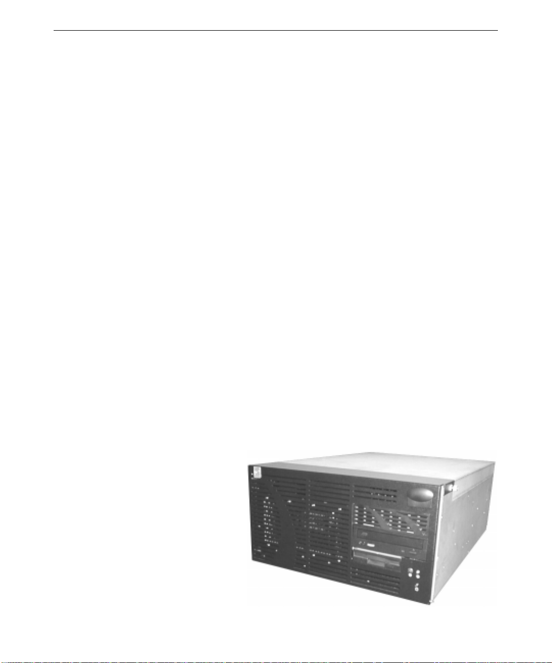
System Hardware
A rack-mount base unit is the heart of the RAX HD Animation Recorder. With its revolutionary
Streaming Multiport Architecture, this base unit provides superior processing and graphics power.
The base unit houses the system disk drive, which contains the operating system, system software,
and default storage for audio data
used by the system. The base unit
also houses graphics, audio, disk,
and other controllers. The base
unit mounts in a standard 19-inch
equipment rack.
Page 11
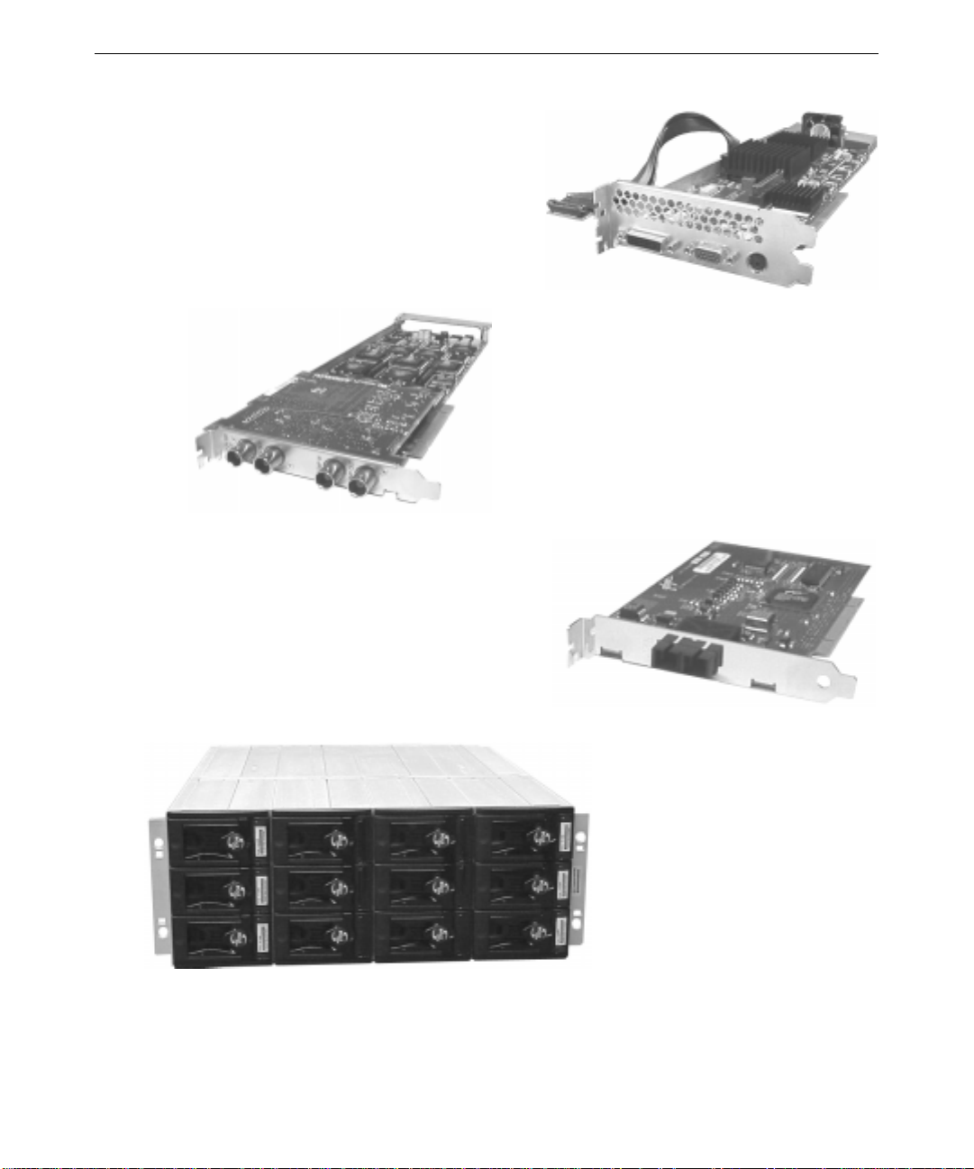
An Intense3D Wildcat 4110 graphics controller
card with video input/output (VIO) is installed in
the base unit’s Accelerated Graphics Port (AGP)
expansion slot. This card provides graphics
control for the system and HD graphics
resolution for producing HD video.
Three QLogic Fibre Channel host bus adapters
(HBAs) are installed in the base unit’s PCI
expansion slots. These cards provide fiber optic
connections from the system to the high-speed,
high-capacity storage array. Fiber optic
connections allow the system to be placed at a
distance from the storage array components.
3
An HD Scan Engine card is installed in one of the
base unit’s Peripheral Component Interconnect
(PCI) expansion slots. This card and its
associated “daughter card” convert graphics data
to video output in HD formats. The card has an
HD serial digital output, and a composite video
sync input and loop-through.
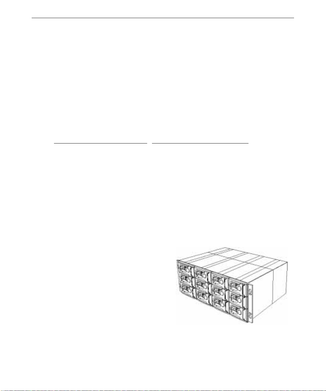
Three Fibre Channel RAID storage
arrays provide the system with
high-speed, high-ca pacity disk
storage. The Fibre Channel disk
drives in these storage arrays
provide a massive storage bank for
uncompressed video data
manipulated by the system. These
storage arrays mount in a standard
19-inch equipment rack.
Page 12
4
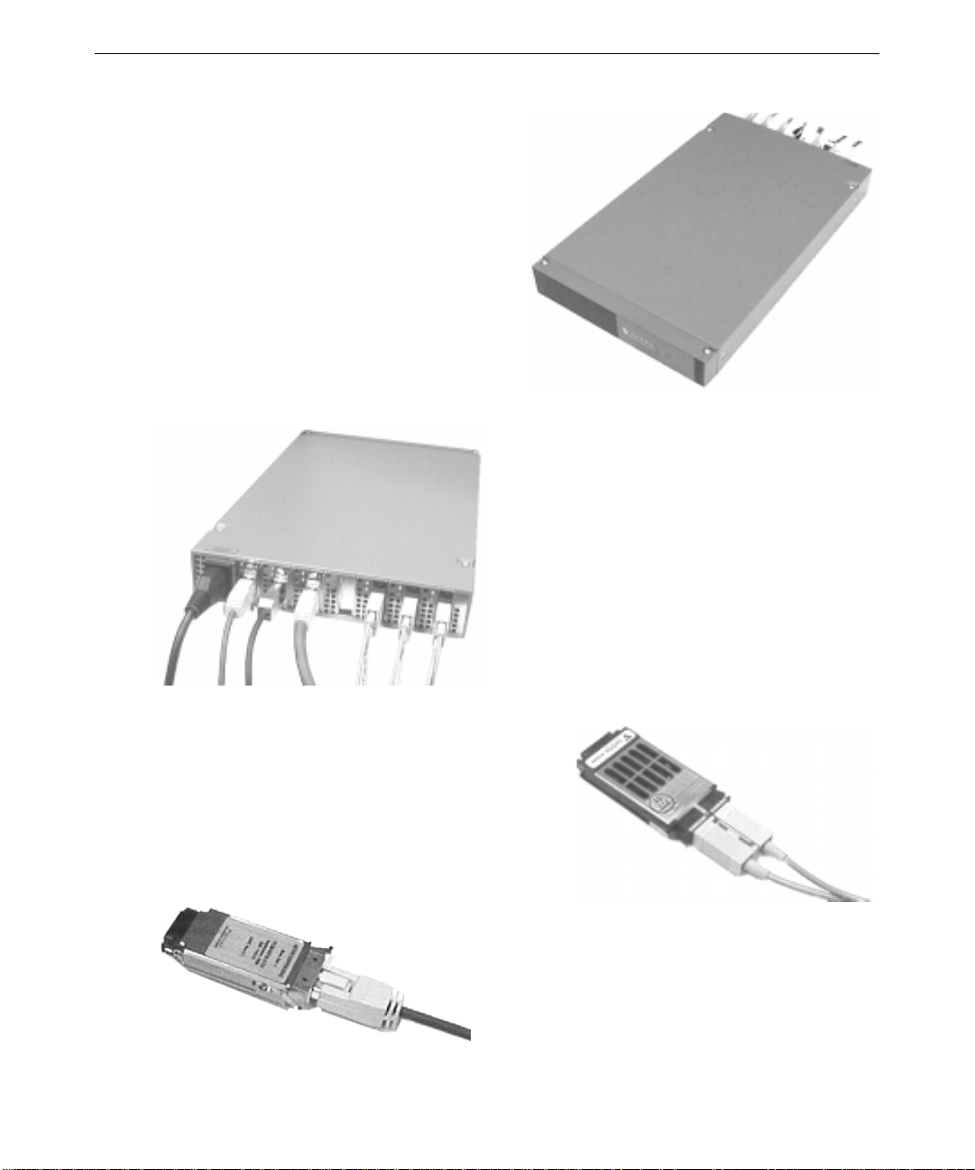
Three Fibre Channel hubs interconnect the
base unit and the three Fibre Channel RAID
storage arrays. The hubs accept fiber optic
connections from the system’s HBAs and
copper connections from the storage arrays.
For uncompromised performance, one hub is
dedicated to each of the three storage arrays.
The hubs can be placed on shelves in an
equipment rack or anywhere within cable
reach of the storage arrays.
Gigabit interconnect (GBIC) ports plug into a
Fibre Channel hub’s rear panel. GBIC ports
provide connection points for fiber optic cables
from the system’s HBAs and copper cables from
the Fibre Channel RAID storage arrays. Any
GBIC port can be installed in any slot in the hub.
GBIC ports are keyed for proper insertion into the
slots.
Fiber optic GBIC ports connect fiber optic cables to
the Fibre Channel hubs. Cables are keyed for proper
insertion into the GBIC ports.
Copper GBICs connect copper cables to the Fibre
Channel hubs. Cables are keyed for proper insertion
into the GBIC ports.
Page 13
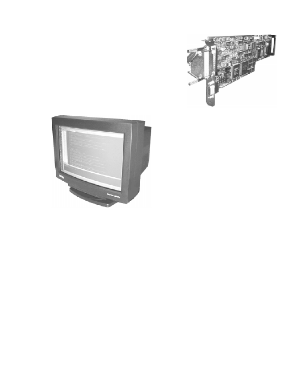
An Antex StudioCard in the base unit provides
professional audio capabilities. The StudioCard
includes 16-bit analog-to-digital (A/D) and digital-toanalog (D/A) converters, a 32-bit 40 MHz digital signal
processor (DSP), and audio-to-video playback lock.
The system includes a 24-inch HD computer
monitor that supports resolutions up to 1920 x
1200. You can use the computer monitor to
display video manipulated by the system, and a
separate video monitor to display final video
output from the system.
5
For more information on these hardware components, see Chapter 2, “Setting Up the Hardware”
and the separate component documentation delivered with the system.
Disk Subsystem
A SCSI system disk drive is installed in the system’s base unit and eight (or twelve) identical Fibre
Channel disk drives are installed in each Fibre Channel storage array. The system disk drive is
formatted with two partitions, which are used for storing operating system software, audio files,
and project files. The Fibre Channel disk drives are formatted as a stripe set and configured as a
single logical disk drive, and are used to provide uncompressed video file storage.
Disk striping is a hardware capability that speeds up data input and output (I/O) from disk storage.
The computer divides the data into pieces and spreads the pieces across the disks in the striped set.
Because the computer transfers data to multiple drives in smaller chunks than would be transferred
to a single drive, the data transfer rate is accelerated. The QLogic host bus adapter handles data
I/O for video file storage.
Page 14

6
The following table summarizes the disk subsystem:
Disk
C System First partition (4 GB)
D Video Storage 24 (or 36) Fibre
E HDAR Second partition of
NOTE Use disk drive D (the Fibre Channel disk drives) only for video file storage. Store
Disk F is the system’s CD-ROM drive. For more information on stripe sets and logical disk drives,
see Chapter 6, “Rebuilding System Software.”
Volume Label Location Format Contents
audio files, project files, and other data only on disk drive E.
System Software
System software for a RAX HD Animation Recorder consists of:
♦ Operating system software
♦ Operating system Service Pack software
♦ Driver software for the ba se system hardware
♦ Driver software for the HD Animation Recorder hardware
of system disk drive
Channel disk drives
system disk drive
File Allocation
Table (FAT)
NTFS Video files
NT File System
(NTFS)
Operating system software
Audio files, project files
♦ Frame Wrangler software
♦ Video File Explorer software
♦ Sample animation frames
All software is installed on the system before shipment. For information on setting up the software
for first-time use, see Chapter 3, “Setting Up the Softwar e .”
If you must reinstall any system software later, you can do so from copies provided on CD-ROMs
delivered with the system. For information on reinstalling HD Animation Recorder driver software
and Frame Wrangler software, see Chapter 6, “Rebuilding System Software.” For information on
reinstalling the operating system and the base system hardware drivers, see the System Guide
delivered with the system’s base unit.
Frame Wrangler is the primary software tool installed on a RAX HD Animation Recorder. With
Frame Wrangler, you can set up and control the harvesting of animation frames from networkbased rendering systems, conversion of animation frames into video clips (or vice versa), and
conversion of video clips into the appropriate video playback format.
Page 15

Frame Wrangler provides versatile control capabilities with familiar videotape recorder (VTR)style controls. Icons offer single-click access to Frame Wrangler functions such as mixing and
audio editing. To satisfy the desire to personalize software, you can choose from a palette of
custom skins to vary Frame Wrangler’s appearance. See Chapter 4, “Getting to Know Frame
Wrangler,” for more information on Frame Wrangler’s interface and capabilities.
Video File Explorer is an additional tool for viewing, manipulating, and extracting animation
frames (rendered image files) that comprise disk-based video files. You can use Video File
Explorer to open a video file, view animation frames in the video file, extract animation frames to
individual image files, and extract audio data to a separate audio file. For more detailed
information on Video File Explorer, see Video File Explorer Help.
Animation Frame Formats
The RAX HD Animation Recorder accepts rendered image files in several animation frame input
formats as input. This lets animators use the animation format they find most productive, from a
wide variety of available animation tools.
The system lets you harvest and build video clips from animation frames in several formats:
7
♦ Windows Bitmap (.
♦ JPEG (.
♦ TIFF (.
♦ Targa (.
♦ Cineon (.
JPG)
TIF)
TGA)
CIN)
♦ SOFTIMAGE PIC (.
♦ Wavefront RLA (.
♦ Intergraph RGB (.
BMP)
PIC)
RLA)
RGB)
From rendered image files in these formats, the system produces disk-based video files. You can
also use Frame Wrangler to save video files as a set of image files in the supported animation
frame formats.
Page 16

8
Video File Formats
The system produces high-definition (HD) video output from rendered image files. These diskbased video file formats are supported:
♦ Audio/Video Interleave (AVI)—Frame Wrangler makes and uses uncompressed OpenDML-
compliant AVI files. The OpenDML AVI file provides high-performance file organization
and supports file sizes greater than 2 GB. Note that at higher data rates, Frame Wrangler
requires an AVI file to contain at least eight frames.
You can also use Frame Wrangler to save video files as a set of image files in the supported
animation frame formats, and to read video files from other sources.
HD Video Formats
The RAX HD Animation Recorder produces high-definition (HD) video output in real time as
disk-based video files. These video files can be played back on HD video equipment and recorded
to an HD videotape recorder (VTR).
For example, it may be more efficient to render a project at a lower resolution and scale up. With
the RAX HD Animation Recorder, you can do this in real time while viewing both the source
material and scaled-up material on different monitors. The system also enables the use of a single
set of rendered images for multiple versions of the same production. With real-time conversions,
rendered data can be recorded to several tape formats in the time it takes to play it back.
In the following list:
♦ The first number is the vertical resolution (lines).
♦ The second number is the video playback rate, or frame rate (frames per second).
♦ 1080/25i supports 1,125 lines and 1,250 lines (some non-visible lines are present).
Progressive (p)
720/59.94p 1035/29.97i 1080/23.98sF
720/60p 1035/30i 1080/24sF
1080/23.98p 1080/25i
1080/24p 1080/29.97i
1080/25p 1080/30i
1080/29.97p
1080/30p
Interlaced (i) Segmented Frame (sF)
Page 17

The possible progressive output options are:
9
Source Displayed At
(frames per second)
Video Output Rate
(frames per second)
23.98 23.98
24 24
25 25
29.97 29.97
30 30
23.98, 29.97, or 59.94 (user-selectable) 59.94
24, 30, or 60 (user-selectable) 60
The possible interlaced output options are:
Source Displayed At
(frames per second)
Video Output Rate
(fields per second)
25 or 50 (user-selectable) 50
23.98, 29.97, or 59.94 (user-selectable) 59.94
24, 30, or 60 (user-selectable) 60
Page 18

10
Page 19

2 Setting Up the Hardware
This chapter describes how to set up and start the hardware components of your RAX HD
Animation Recorder.
Before You Begin
Review the RAX HD Animation Recorder Quick Connect Diagram (delivered with the system) to
see how system components connect and where they should reside in relation to each other.
Before you be gin setting up the HD Animation Recorder hardware:
♦ Ensure that you have adequate AC power on site. If the site has 20A service, you can connect
all of the basic hardware to the same service line. If the site has 15A service, you must have
two separate, dedicated 15A service lines for the basic hardware. See "Connecting to AC
Power" in this chapter for more information.
♦ Ensure that the base unit hardware is set up correctly. See “Setting Up the Base Unit
Hardware” in this chapter.
♦ Ensure that the system’s base unit is shut down and that base unit power is turned off (the
power cord is disconnected from its AC outlet). See the System Guide delivered with the
system for more information.
11
♦ Remove the Fibre Channel RAID storage arrays, Fibre Channel hubs, associated hardware,
and cables from their shipping containers.
Before you attempt to mount the Fibre Channel RAID storage arrays and hubs in a standard 19inch equipment rack, note that:
♦ The storage arrays mount in standard 19-inch equipment racks in use at your site.
♦ A vertical unit (U) is a standard measurement equivalent to 1.75 inches of vertical rack space.
Small markers on the rack mounting rails usually indicate each vertical unit. For more
information, see the documentation for the racks in use at your site.
♦ Each storage array occupies 4U of vertical rack space. The three hubs, their rack-mount
shelves, and the associated blanking plate together occupy 3U of vertical rack space.
♦ Measure the available vertical space in your racks and mark the locations of each component
before you start installation.
Page 20
12
Setting Up the Base Unit Hardware
A rack-mounted base unit is the heart of your RAX HD Animation Recorder. You must set up the
base unit hardware before continuing with the procedures in this chapter.
To set up the base unit hardware:
1. Follow the instructions in the base unit’s System Guide to mount the base unit in an equipment
rack and set up the basic base unit hardware.
2. Follow the instructions in the Intense3D Wildcat 4110 documentation to connect the computer
monitor to the Wildcat 4110 VIO graphics controller in the base unit.
Expansion cards for the RAX Animation Recorder system are installed in the base unit as follows:
Slots
Slot 1 (AGP) and Slot 2 (PCI) (Left) Wildcat 4110 VIO graphics controller
Slot 3 (PCI) HD Scan Engine
Slot 4 (PCI) QLogic Host Bus Adapter
Slot 5 (PCI) QLogic Host Bus Adapter
Slot 6 (PCI) QLogic Host Bus Adapter
Slot 7 (PCI) (Right) Antex StudioCard audio controlle r
Expansion Card
Mounting the Fibre Channel RAID Storage Arrays
The system comes with three Fibre Channel RAID storage arrays. Each storage array is a rackmount chassis that supports up to 12 Fibre Channel disk drives and associated power modules,
input/output modules, and RAID controller
modules.
For more information on the storage array and
its associated equipment, see the storage array
documentation delivered with the system.
You will mount three Fibre Channel RAID
storage arrays in one or more standard 19-inch
equipment racks in use at your site. Repeat
the following steps for each array that you
mount.
WARNING Do not install disk drives in a storage array before you mount the storage array
in a rack! Doing this could lead to disk drive damage such as head crashes.
Subsequent disk drive failures may not be noticeable for three to six months.
Page 21
13
To mount a Fibre Channel RAID storage array in a rack:
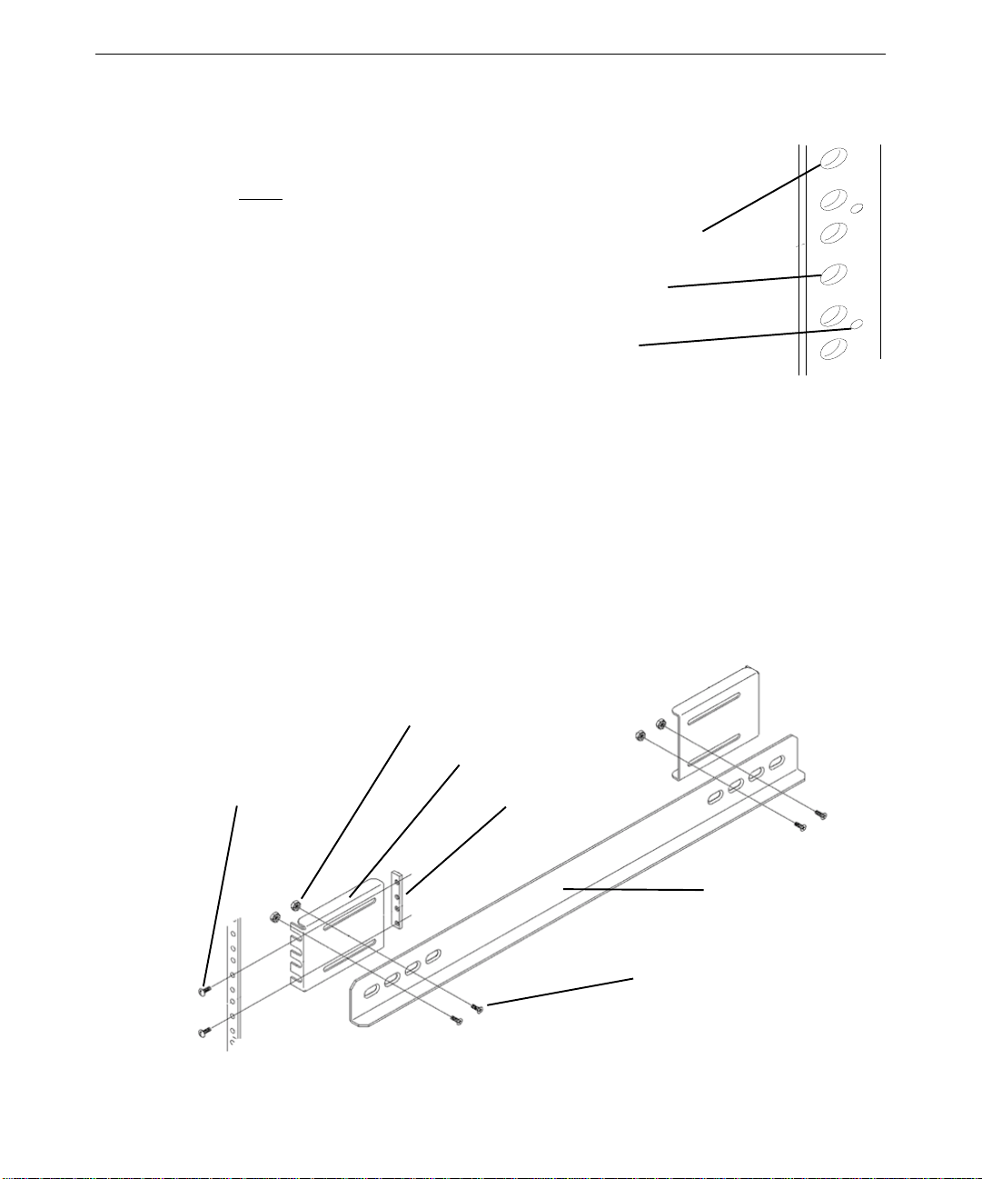
1. On each rack rail (front and back), locate the vertical unit (U) marker that will
be level with the bottom of the chassis. Mark the second and fifth mounting
holes above the U marker.
Fifth mounting hole
Second mounting hole
Vertical unit (U) marker
2. On each rack rail (front and back), insert b utton-head screws through the mounting holes
marked in step 1 and into the top and bottom holes of a bar nut. Leave the screws loose
enough to allow a mounting bracket to be fitted onto them later. See the following figures.
3. Attach two mounting brackets to each chassis rail with flat-head screws and lock nuts. Leave
the screws just loose enough to allow movement of the brackets on the rails. Se e the
following figures.
4. On each pair of rack mounting rails (front and back), fit the mounting brackets of a chassis rail
onto the button-head screws. Insert the teeth of each mo unting bracket between the bar nut
and the rack rail. Tighten the button-head screws. See the following figures.
5. On each chassis rail, tighten the flat-head screws to secure it to its mounting brackets. See the
following figures.
Lock nuts
Mounting bracket
Button-head
screws
Bar nut
Chassis rail
Flat-head screws
Page 22

14
Mounting bracket
Chassis Rail
6. On each front rack rail, install a tinnerman nut
in the fifth mounting hole above the top
mounting bracket scr ew.
Tinnerman nut
WARNING The following figures show disk drives installed in the storage array. Do not
install disk drives in a storage array before you mount the storage array in a
rack! Doing this could lead to disk drive damage such as head crashes.
Subsequent disk drive failures may not be noticeable for three to six months.
Page 23

7. Slide the bottom of a
storage array chassis onto
the chassis rails. Push the
storage array back until
the brackets on either side
of the chassis touch the
front rack rails.
The upper holes in the
chassis brackets should
match up with the
tinnerman nuts on the
front rack rails.
8. Fit a bracket cover onto each of the chassis
brackets. Insert button head screws through the
holes in the chassis bracket covers and tighten
them.
15
Disk drive installation instructions are covered in “Installing Storage Array Disk Drives” later
in this chapter.
Page 24

16
Mounting the Fibre Channel Hubs
The system comes with three Fibre
Channel hubs. Each hub interconnects
the system’s base unit to a Fibre Channel
RAID storage array. For uncompromised
performance, each storage array has its
own hub.
For more information on the hub, see the
hub documentation delivered with the
system.
You can place the hubs on two shelves
that you mount in a standard 19-inch equipment rack in use at your site. If you do not have rack
space, you can place each hub anywhere within 3 meters (9.8 feet) of its storage array.
To mount the shelves and hubs in a rack:
1. Remove the shelves and their
brackets from the packaging.
Loosely attach both brackets to
each shelf using the four screws
provided
2. Two screws in each corner will
secure each shelf to the rack.
Decide where you want to install
each shelf into the rack and place
Tinnerman nuts on the front corner
posts of the rack.
3. Place each shelf into the rack with
the brackets inside the two back
corner posts. Secure each shelf to
the rack with two screws at each
corner. Make sure each shelf is
level before tightening the screws.
Shelf Bracket
Back Corner Post
Shelf Bracket
Page 25

4. You can place up to two
hubs on each shelf. Make
sure the GBIC ports on the
back of the hub face the back
of the rack.
5. If you want to hide the hubs
on the upper shelf from view,
secure a blanking plate to the
rack immediately above the
upper shelf with two
Tinnerman nuts and two
screws.
Blanking Plate
17
Shelf
Connecting a Video Device to the System
After you mount the Fibre Channel storage array chassis and hubs in a rack, you can begin
connecting the various system components together. Start by connecting a video device, such as
an HD monitor or a videotape recorder (VTR), to the system’s base unit.
NOTE The computer monitor is connected to the base unit during base unit setup. See the
System Guide
connections between the base unit and the HD Scan Engine card. For information
on internal connections, see “Graphics/Scan Engine Internal Connection” later in this
chapter.
delivered with the system for more information. There are no external
Page 26

18
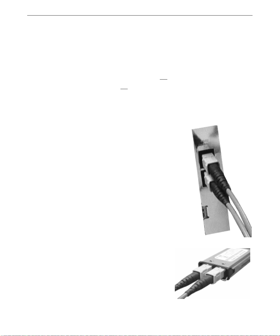
To connect a video device to the system:
1. Connect a 75-ohm BNC cable to the SDI OUT YUV port on the HD
Scan Engine card. Then connect the cable to an SMPTE 292M input
port on the video device.
SDI OUT YUV port
2. To genlock the HD Scan Engine outp ut to an analog composite house
sync (reference) signal, connect a BNC cable to the COMP REF IN
(Composite reference input) port on the HD Scan Engine card. Then
connect the cable to the appropriate output port on the house sync
source.
NOTE The HD Scan Engine card provides a loop-through of the
reference input signal at the COMP REF OUT (Composite
reference output) port, if needed. If no cable is connected to
this port, you must connect the supplied 75-ohm terminator to it.
COMP REF IN port
3. For a device that requires machine control,
connect the supplied RS-232-to-RS-422 machine
control cable to the software-selected serial port
(COM 1 by default) on the back of the system’s
base unit. Then connect the cable to the RS-422
device control port on the device.
You must use the supplied RS-232-to-RS_422
cable. You may connect the supplied cable to
another RS-422 cable if you need more cable
length.
Serial Port 1 (COM 1)
COMP REF OUT port
Page 27
Connecting the Base Unit to the Storage Arrays
To connect the system’s base unit to the Fibre Channel RAID storage arrays, route and connect
cables from the base unit to the Fibre Channel hubs, and from the hubs to the storage arrays.
Before you be gi n connecting the base unit to the storage arrays and hubs, note that:
♦ Each QLogic host bus adapter (HBA) connects to one hub.
♦ Each storage array connects to one hub.
♦ A 50-meter (164-foot) fiber optic cable connects the base unit to each rack-mounted hub.
♦ A 3-meter (9.8-foot) copper cable connects each rack-mounted storage array to its hub.
To connect the base unit to a storage array:
1. Connect a fiber optic cable to one of the base unit’s QLogic
host bus adapter (HBA) cards. The cable is keyed for
proper connection.
2. Route the cable to a Fibre Channel hub.
19
3. Connect the cable to a fiber optic GBIC port. The
cable is keyed for proper connection.
Page 28

20
4. Insert the GBIC port into any slot in the back of a hub.
The port is keyed for proper connection.
5. Connect a copper cable
to the bottom HSDCC
port in the back of a
storage array. The cable
is keyed for proper
connection.
6. Route the cable to the
hub you used in step 4.
7. Connect the cable to a copper GBIC port. The
cable is keyed for proper connection.
8. Insert the GBIC port into any slot in the back of the hub
you used step 4. The port is keyed for proper connection.
9. Repeat steps 1 through 8 to connect each of the remaining
storage arrays to each of the remaining hubs.
Page 29

Connecting Audio Devices
After connecting the system’s base unit to the storage arrays, you
can connect audio devices to the audio ports on the back of the base
unit. See the device’s documentation for instructions on connecting
an audio device to the appropriate port.
See the separate Antex StudioCard documentation (delivered with
the system) for information on connecting audio devices to the
StudioCard.
21
Line In
Installing Storage Array Disk Drives
Each Fibre Channel RAID storage array ships
with one installed RAID controller and either
eight (standard) or twelve (optional) uninstalled
Fibre Channel disk drives. Each disk drive is in a
carrier that installs into a bay in a storage array.
For more information on the storage arrays and
the disk drives, see the storage array
documentation delivered with the system.
Before the system shipped from the factory:
♦ Eight (standard) or twelve (optional) disk drives were installed in each storage array.
♦ Each storage array was configured for RAID Level 5 using RAID controller software installed
on the base unit.
♦ The disk drives in each storage array were configured as one (standard) or two (optional) data
disks using RAID controller so ftware insta lled on the system.
♦ The three storage arrays were striped as one logical disk drive on the system using the
operating system's Disk Administrator software.
Line Out
Microphone
♦ Each storage array and its disk drives were labeled to ensure proper installation at your site.
♦ The disk drives were removed from the storage arrays for shipment.
You must install all of the disk drives in the storage arrays. You must also ensure that you install
the disk drives in the configuration set up at the factory.
Page 30

22
WARNING If you do not install the disk drives as labeled, the RAID configuration and disk
striping will not work, and the storage arrays will not function correctly. You
must install each disk drive in the correct bay in the correct storage array, as
described in these instructions and on the installation labels.
Each storage array has an installation label on the top of its chassis.
This label:
♦ Identifies the storage array by letter (A, B, or C) and color (red,
green, or blue)
♦ Identifies the disk drive bays (1 thro ugh 12) in the storage array
The following figure shows the location of the installation label on a
storage array chassis.
Location of installation label
on storage array chassis
Page 31

Each disk drive has an installation label on the top of its carrier. This
label:
♦ Identifies the storage array to which the disk drive belongs by letter
(A, B, or C) and, for standa rd disk drives (1 through 8), by color
(red, green, or blue)
♦ Identifies the ba y (1 through 12) in which the di sk drive resides.
The following figure shows the location of the installation label on a disk
drive carrier:
Location of installation label
on disk drive carrier
23
Before you install each disk drive in a storage array:
♦ Match the letter on the disk drive label with the letter on the storage array label. For example,
install a disk drive with an A label only in the chassis with an A label.
♦ Match the number on the disk drive label with the bay in the storage array. For example,
install the disk drive with a 1 on its label only in bay 1.
♦ The eight standard disk drives must be i nst alled in bays 1 through 8 (see below).
♦ The four optional disk dr i ves must be installed in b ays 9 through 12 (see below).
9
5
1
10
6
2
11
7
3
12
8
4
Page 32

24
To install a disk drive in a storage array:
1. Press the left side of the carrier
faceplate to release the carrier handle.
2. Insert the disk drive carrier into the
chassis.
3. Push the carrier gently into the chassis
until it stops.
4. Press the left side of the carrier handle
to draw the carrier into the chassis
until the handle clicks closed.
5. If you are installing only eight disk
drives in a storage array, install the
supplied faceplate blanks in the open
disk drive bays. This ensures proper
airflow to cool the entire storage array.
6. For added security, use the supplied
carrier lock key to lock each carrier
handle and prevent removal of the disk
drives. Insert the key in the socket on
the carrier handle and turn it counterclockwise until the indicator in the handle shows green. To unlock the carrier handle, turn the
key clockwise until the indicator in the handle shows black.
Connecting to AC Power
After you have connected the system’s base unit to the storage arrays, connect the base unit, the
storage arrays, and the hubs to AC power.
CAUTION To meet UL requirements, connect the basic hardware components to AC power as
follows.
If your site has 15A service, connect the base unit and the computer monitor to the
AC power outlets on one 15A dedicated service line. Connect the three Fibre
Channel storage arrays and the three Fibre Channel hubs to AC power outlets on a
separate 15A dedicated service line.
If your site has 20A service, you can connect the base unit, the computer monitor,
the three Fibre Channel storage arrays, and the three Fibre Channel hubs to AC
power outlets on the same AC service line.
Connect other hardware (such as audio and video devices) to AC outlets on a
separate service line from the basic hardware components.
Page 33

To connect to AC power:
1. At the back of each Fibre Channel
hub, connect an AC power cord to
the AC power receptacle.
2. Connect the AC power cord from
each hub to an AC power outlet.
(See
CAUTION at the beginning of
this section.) This applies power
to each hub.
3. At the back of each Fibre Channel storage array,
turn the keyswitch to the
SERVICE position.
Keyswitch in SERVICE position
4. At the back of each storage
array, connect a split power
cord to both AC power
receptacles.
25
CAUTION Do not connect any other AC
power cords to the storage
arrays. The split power cord
provides a single point of
disconnect for each storage
array.
5. Connect a split AC power cord
from each storage array to an
AC power outlet. (See
CAUTION at the beginning of
this section.) This applies
standby power to each storage
array.
6. Ensure the computer and video monitors are connected to AC power outlets as needed. (See
CAUTION at the beginning of this section.)
CAUTION Before reconnecting the base unit’s AC power cord, you may want to learn more
about system power, startup, and shutdown. See the
the system for more information.
7. Reconnect the power cord for the base unit to its AC power outlet. (See CAUTION at the
beginning of this section.) This applies standby power to the base unit.
System Guide
delivered with
Page 34

26
For more detailed information on connecting the storage arrays, the hubs, the monitors, and the
base unit to AC power, see the documentation delivered with these components.
Controlling System Power
CAUTION Before proceeding, see the
instructions on applying standby power and full power to the system’s base unit.
NOTE Power is applied to the Fibre Channel storage arrays and hubs when they are
connected to AC power.
System Guide
delivered with the system for complete
To turn on power to system components:
1. At the back of each Fibre Channel RAID storage
array, turn the keyswitch to the
RUN position. This
applies full power to each storage array.
Keyswitch in RUN position
2. Turn on power to the video and computer monitors.
3. Apply full power to the base unit.
To turn off power to system components:
1. Shut down the operating system and apply standby power to the base unit.
2. Turn off power to the video and computer monitors.
3. At the back of each storage array, turn the
keyswitch to the
SERVICE position.
4. At the back of each storage array, press and hold
the STANDBY button for at least 2 seconds. This
returns each storage array to standby power.
STANDBY button
Keyswitch in SERVICE position
5. To completely remove AC power from the base unit, the hubs, and the storage arrays,
disconnect their AC power cords from the AC power outlets.
For more information on controlling base unit power, see the System Guide delivered with the
system.
Page 35

Graphics/Scan Engine Internal Connection
The Wildcat 4110 VIO graphics controller card and the HD Scan Engine card are connected
internally by a ribbon cable. If you must replace one or both of these cards, you must first
disconnect the ribbon cable. When both cards are in place, the ribbon cable must connect them to
ensure proper system operation.
The following figure shows the ribbon cable and its connection to the Wildcat graphics controller
and the HD Scan Engine card.
27
Ribbon cable
Connection to
Wildcat 4110 VIO card
Connection to
HD Scan Engine card
Page 36

28
Page 37

3 Setting Up the Software
This chapter describes how to set up the software for your RAX HD Animation Recorder.
Setting Up Base Unit System Software
A rack-mounted base unit is the heart of your RAX HD Animation Recorder. You must set up the
base unit operating system first, and then set up the remaining system software. Follow the
instructions in the base unit’s System Guide to set up the base unit’s operating system and to
configure the base unit for use.
See the separate Antex StudioCard documentation (delivered with the system) for information on
setting up and using the StudioCard and its associated software.
Before using Frame Wrangler for the first time, do the following:
♦ In the operating system's Control Panel, go to Display » Settings and set the system's video
display resolution to 1920 x 1200. This provides a 1920 x 1080 video preview region and a
control surface area on the computer monitor display.
♦ In the operating system's Settings program menu, go to Taskbar and set the taskbar to auto-
hide.
29
♦ Defragment the system’s disk drives. This helps use the system’s disk space effectively. You
can use a free disk defragmentation program such as Diskeeper Lite (available on the World
Wide Web at http://www.diskeeper.com) to manually defragment the disk drives. You can
also purchase a disk defragmentation program that wo rks automatically.
Setting Up RAX HD Animation Recorder Software
RAX HD Animation Recorder software,
including hardware driver software ,
Frame Wrangler software, and Video File
Explorer software, was installed and
configured b efore shipment. You only
need to take a few steps to configure
Frame Wrangler for its first use.
Frame Wrangler starts when you log on to
the operating system. (For more
information, see Chapter 4, “Getting to
Know Frame Wrangler.”) When Frame
Wrangler starts for the first time, the HD
Output Configurati on dialog displays.
Page 38

30
You must set the HD video output format so Frame Wrangler will produce video output that the
HD equipment connected to the system will accept. The HD Output Configuration dialog displays
each time you start Frame Wrangler until you configure the HD video output format.
You can change the settings in the HD Output Configuration dialog later, if needed. To do this, go
to Configure » HD Output on Frame Wrangler's Main Panel (see Chapter 4, “Getting to Know
Frame Wrangler”).
Finding Frame Wrangler and Video File Explorer
Frame Wrangler and Video File Explorer are both available from the operating system Start menu:
♦ To find Frame Wrangler, go to Frame Wrangler in the Frame Wrangler program menu.
♦ To find Video File Explorer, go to Video File Explorer in the Frame Wrangler program menu.
For detailed information on Video File Explorer, see Video File Explorer Help.
Reinstalling and Reconfiguring System Software
If you have to reinstall or reconfigure the base unit operating system or any of the base unit
hardware drivers, see the System Guide delivered with the system.
If you have to reinsta ll or reconfigure RAX HD Animation Recorder software, incl uding Frame
Wrangler software, see Chapter 6, “Rebuilding System Software.”
Page 39

4 Getting to Know Frame Wrangler
This chapter provides basic information on Frame Wrangler software, the primary tool on your
RAX HD Animation Recorder system. For more information on Frame Wrangler, its controls, and
its functions, see the online Frame Wrangler Help.
Starting and Stopping Frame Wrangler
Frame Wrangler starts when you log on to the operating system. To ensure that Frame Wrangler
can find image files produced by your site’s rendering systems, make sure you lo g on to the
appropriate network domain.
To start Frame Wrangler if it is not already running:
♦ Double-click the Frame Wrangler icon on the operating system desktop, or
♦ Go to Frame Wrangler in the Frame Wrangler program menu.
When you start Frame Wrangler for the first time, the HD Output Configuration dialog displays
(see Chapter 3, “Setting Up the Software”). You must set the HD video output format so Frame
Wrangler will produce video output that the HD equipment connected to the system will accept.
The HD Output Configuration dialog displays each time you start Frame Wrangler until you
configure the HD video output format. You can cha nge these settings later by going to Configur e
» HD Output in Frame Wrangler's Main Panel.
31
Frame Wrangler stops when you log off from the operating system or shut down the system.
To stop Frame Wrangler while the operating system is running:
♦ Go to File » Exit in Frame Wrangler's Main Panel, or
♦ Click the Exit window control on Frame Wrangler's Main Panel.
WARNING Video builds are terminated if you log off from the operating system or shut
down the system, and do not resume when you log on again to the operating
system. If you have set up video builds, do not log off from the operating
system or shut down the system until those builds have completed.
If a video build is terminated, the resulting video clip contains any rendered frames that were
processed up to the point at which termination occurred.
Page 40

32
Video Clips, Video Sequences, and Playlists
Frame Wrangler operation is organized primarily around three objects:
♦ A video clip is a processed collection of rendered image files (animation frames). Frame
Wrangler helps you find and process image files into video clips.
♦ A video sequence is a collection of video clips. Frame Wrangler helps you organize clips into
a sequence, play and edit the sequence, and record the sequence to tape. Frame Wrangler also
helps you convert a video sequence into High Definition (HD) video output.
♦ A playlist is a set of video clips collected into an organized video sequence. You can
manipulate the content, playback, and organization of clips in a playlist, and save it to or
restore it from a file. Playlist files are named file.
viewed as a storyboard on which you manipulate the content and organization of a playlist.
SZL. In Frame Wrangler, a playlist is also
Interface
When you log on to the RAX HD Animation Recorder, Frame Wrangler runs and the Frame
Wrangler interface displays. The Frame Wrangler interface consists of:
♦ A Main Panel that displays at the top of the computer monitor.
♦ A Storyboard Panel and a VTR Control Panel that display when selected.
♦ A Video Window that occupies the rest of the computer monitor.
Main Panel
Video
Window
VTR Control Panel or
Storyboard Panel
Page 41

The operating system interface and controls are hidden by the Frame Wrangler interface. The
taskbar and Start menu stay hidden at the bottom of the computer monitor unless needed. The
Main Panel and the Video Window hide any desktop icons.
To display the operating system controls or interface:
♦ Move the cursor to the bottom of the screen to display the taskbar, or
♦ Press the keyboard’s Windows button to display the taskbar and the Start menu, or
♦ Use the Main Panel window controls to minimize the Frame Wrangler interface.
Main Panel
The Main Panel contains all the video play and position controls, and controls for displaying the
Storyboard Panel and the VTR Control Panel. By default, the Main Panel displays at the top of the
computer monitor.
You can move the Main Panel to the bottom of the computer monitor if needed and lock the panel
in place. To do this, go to Configure » Skins in the Main Panel.
The major controls in the Main Panel are:
33
♦ Menus that control Frame Wrangler operation and configuration.
♦ The toolbar, a strip of buttons that give you quick access to common tasks or activities. You
can also perform these tasks or activities by selecting the appropriate options in the menus.
♦ Play controls, buttons you use to control playback of video clips in an open playlist.
♦ Position controls, sliders and wheels you use to manipulate your position in the video clips in
an open playlist.
♦ Edit controls, fields and buttons you use to mark sections of a video sequence in an open
playlist for editing.
♦ Record-to-tape, a button you use to record a video sequence to tape.
♦ Fly-out controls, buttons that display the other panels.
Toolbar
Position Controls
Play Controls
Record-to-Tape
Edit Controls
Menus
Fly-Out Controls
Page 42

34
For more information on the Main Panel and its controls, see the online Frame Wrangler Help.
Storyboard Panel
The Storyboard Panel contains the video clip storyboard and controls for manipulating vid eo clips
in an open playlist. By default, the Storyboard Panel displays to the right of the Main Panel.
You can change the way the Storyboard Panel flies out from the Main Panel if needed. To do this,
go to Configure » Skins in the Main Panel.
The major controls in the Storyboard Panel are:
♦ The storyboard, which represents an open playlist and displays the video clips in that playlist.
An image and a file name display for each video clip on the storyboard.
♦ Storyboard controls, which you use to manipulate the content of the storyboard.
Storyboard controls Storyboard
For more information on the Storyboard Panel and its controls, see the online Frame Wrangler
Help.
VTR Control Panel
The VTR Control Panel contains controls for operating a videotape recorder (VTR) connected to
the RAX HD Animation Recorder system. By default, the VTR Control Panel displays to the right
of the Main Panel.
You can change the way the VTR Control Panel flies out from the Main Panel if needed. To do
this, go to Configure » Skin in the Main Panel.
The major controls in the VTR Control panel are:
♦ Play controls, buttons you use to control playback of the tape.
♦ Position controls, sliders and wheels you use to manipulate your position on the tape.
♦ Edit controls, fields and buttons that let you mark sections of the tape for editing.
Page 43

For more information on the VTR Control Panel and its controls, see the online Frame Wrangler
Help.
Video Window
The video window is the area of the computer monitor in which Frame Wrangler plays video clips
or video sequences. By default, the video window is below the Main Panel.
You can change the display and look of the video window if needed. To do this, go to Configure »
Options in the Main Panel.
35
Play Controls Edit Controls
Position Controls
Page 44

36
Menus
The Frame Wrangler Main Panel contains five menus. These menus give you access to controls
for playing, viewing, and editing video clips and video sequences, configuring the operation of and
interface for Frame Wrangler, and gaining access to detailed online Help.
For more information on the menus and their options, see the online Frame Wrangler Help.
File Menu
The File menu conta ins options for opening, buildi ng, and saving video clips and playlists.
New—Clears the open playlist.
Open—Finds and opens an existing playlist.
Save—Saves an open playlist as a playlist file (file.
Save As—Saves an open playlist as a playlist file, a video file, or a series of image files.
Open Video—Opens a video clip.
Build Video—Starts the Build Video wizard, which sets up a frame harvest and builds a video clip.
See “Build Video Wizard” in this chapter for more information.
Video Properties—Displays information about a video clip.
Recent—Opens recently opened video clips or playlist files.
Play Menu
The Play menu contains options for playing and editing video clips in an open playlist.
Loop—Enables looped playback of an open playlist.
Audio—Enables playback of audio files associated with video clips.
Edit Playlist—Edits the content of a playlist.
Replace Frames—Replaces bad frames in a video clip.
SZL).
Page 45

View Menu
The View menu contains options for changing the way you view the Frame Wrangler interface and
for how you use Frame Wrangler with a videotape recorder (VTR) connected to the system.
On Top—Keeps the Main Panel and other displayed panels on top of other items on screen.
Storyboard—Displays the Storyboard Panel.
VTR Control—Displays the VTR Control Panel.
VTR E-E—Sets a VTR connected to the system to pass the video signal on its input directly
through to its output—for example, directly to a vi deo monitor connected to the VTR.
Stop Field—Sets which video fields to display when playback stops.
Video Levels—Sets color leve ls, contrast, and brightness of a video clip.
Time Format—Sets the display format for the counters and edit fields in the Main Panel and the
VTR Control Panel.
37
Configure Menu
The Configuration menu contains options for configuring the Frame Wrangler interface and Frame
Wrangler o peration.
Skins—Changes the appearance of the Frame Wrangler interface.
Options—Sets default options for Frame Wrangler operation.
HD Output—Sets defaul t options for HD output from Frame Wrangler to a vi deo device (such as a
VTR) connected to the system.
VTR Control Options—Sets options for controlling a VTR connected to the system.
Help Menu
The Help menu provides access to the online Frame Wrangler Help system and version
information.
Help Topics—Displays the online Frame Wrangler Help system.
About Frame Wrangler—Displays version information about your Frame Wrangler software.
Page 46

38
Keyboard Controls
From the system’s keyboard, you can control several commonly used Frame Wrangler functions on
the Main Panel and on the VTR Control Panel.
Main Panel Keyboard Controls
The Main Panel must be selected for these controls to work.
Key
SPACE BAR Play a video sequence or stop a playing video sequence
ESC Stop playing a video sequence
F Fast forward to the end of a video sequence
R Rewind to the start of a video sequence
I Set the start point in a video sequence (same as the Mark In button)
O Set the end point in a video sequence (same as the Mark Out button)
S Go to the start point in a video sequence
E Go to the end point in a video sequence
SHIFT + X Clear start and end points in a video sequence (same as the Mark Clear
Function
button)
↑
↓
→
←
SHIFT + →
SHIFT + ←
CTRL + TAB Go to the first frame of the next video clip in a sequence; if you are in the
Go to the start point in a video sequence (same as the S key)
Go to the end point in a video sequence (same as the E key)
Go to the next frame in a video sequence
Go to the previous frame in a video sequence
Go forward five frames in a video sequence
Go back five frames in a video sequence
last clip in a sequence, go to the first frame of that clip
CTRL + SHIFT + TAB Go to the first frame of the previous video clip in a sequence; if you are in
the first clip in a sequence, go to the first frame of that clip
Page 47

VTR Control Panel Keyboard Controls
The VTR Control Panel must be selected for these controls to work.
39
Key
SPACE BAR Play a tape or stop a playing tape
ESC Stop playing a tape
F Fast forward to the end of a tape
R Rewind to the start of a tape
I Set the start point on a tape (same as the Mark In button)
O Set the end point on a tape (same as the Mark Out button)
S Go to the start point on a tape
E Go to the end point on a tape
SHIFT + X Clear start and end points on a tape (same as the Mark Clear button)
↑
↓
→
←
Function
Go to the start point on a tape (same as the S key)
Go to the end point on a tape (same as the E key)
Go to the next frame on a tape
Go to the previous frame on a tape
Build Video Wizard
The Build Video wizard is a part of
Frame Wrangler that you will use
frequently. This wizard steps you
through the proce ss of setting up a frame
harvest and building a video clip. Using
the Build Video wizard, you can choose
to build a video clip immediately, or set
up a frame harvest and a video build for
later.
Page 48

40
If you choose to build a video clip
immediately, the Build Video wizard
helps you find and a rrange rendered
image files to use in building the clip.
The wizard then helps you define the
video clip you want to create, including
the clip’s image size, frame rate, and
even or odd field dominance (to match
NTSC video input with HD/PAL video
input).
If you choose to schedule a frame
harvest and a later video build, the
Build Video Wizard helps you define
where to find the rendered image files
and how many will be used to create
the video clip.
Page 49

Help
41
The wizard then helps you schedule the
video build.
Finally, as with an immediate build, the
wizard helps you de fine the video cl i p
you want to create.
For more information on using the Build
Video wizard, see Chapter 5, “Using
Frame Wrangler,” and the online Frame
Wrangler He lp.
Frame Wrangler Help uses enhancements
to Windows Help. A Contents window
displays on the right and a Topics
window displays on the left. You can
use the Contents window to locate and
display information in the Topics
window.
Contents Window
Topic Window
To display the online Help system:
♦ Click Help in Frame Wrangler's Main Panel toolbar, or
♦ Go to Help » Help Topics in Frame Wrangler's Main Panel, or
♦ Go to Help in the Frame Wrangler program menu.
To move around in the Help system:
♦ If the Contents window is not visible, click Help Topics to display it.
♦ In the Contents window, double-click a “book” to display its topics or a topic to display it.
♦ In the Topic window, click underlined green text to jump to a related topic.
♦ Click Back to move back through a set of topics you have recently displayed.
♦ When displayed, click >> and << to browse a set of related topics.
Page 50

42
To use other Help system features:
♦ Click Help Topics to hide the Contents window and provide more space to display a topic. To
restore the Contents window, click Help Topics again.
♦ Click the Index tab to display an index of words and phrases in the Help system.
♦ Click the Search tab to do a full-text search for words or phrases in the Help system.
♦ Click Print to print the currently displayed topic.
Page 51

5 Using Frame Wrangler
This chapter provides basic information on using Frame Wrangler software, the primary tool on
your RAX HD Animation Recorder system. For more detailed information on using Frame
Wrangler, its controls, and its functions, see the online Frame Wrangler Help.
Overview
You can use Frame Wrangler to enhance and simplify animation production, and to produce High
Definition (HD) video for animation reviews and output to tape.
Build video clips—You can set up Frame Wrangler to gather (harvest) image files (animation
frames) from rendering systems at your site. After setting up a frame harvest, you can start it
immediately or schedule a later start time. Once started, the frame harvest completes
automatically, ending in the creation of a video file (video clip). When you build video clips as
image files are rendered, Frame Wrangler can harvest rendered image files from many generational
sites as they are created. This helps you arrive at prepared video sequences almost immediately
after rendering is complete
Collect video clips—You can use Frame Wrangler to locate the video clips it created and organize
them into playlists. A playlist organizes a sequence of video clips for review and processing.
43
Review video clips—You can user Frame Wrangler to review playlist content. You can also
review information on each video clip produced by Frame Wrangler to help identify any rendering
problems. If needed, you can launch corrective renders and set up Frame Wrangler to accept them
as they complete.
Process video clips—You can use Frame Wrangler to make changes to playlists and to video clips
in a playlist. You can add, remove, and rearrange video clips in a playlist. Among other things,
you can replace missing or blown frames in a clip, adjust color levels, and associate audio files
with video clips.
Produce video output—You can use Frame Wrangler to save a playlist to an HD video file, play
the HD video file to an HD display device, and record the HD video file to tape.
Page 52

44
Optimizing Software Performance
When using Frame Wrangler, take the following steps to optimize software performance:
♦ Before using the system, defragment its disk drives. Once you start using the system,
defragment its disk drives periodically. This uses the system’s disk space effectively.
You can use a free disk defragmentation program such as Diskeeper Lite (available on the
World Wide Web at http://www.diskeeper.com) to manually defragment the disk drives.
You can also purchase a disk defragmentation program that works automatically.
♦ Do not run other programs or build video clips during video playback.
♦ Avoid using screen save r software. If you want to lock the system to prevent unauthorized
use, press
Lock Workstation. You will need your user name and password to unlock the system.
♦ Create and store video files only on the default disk drive for video storage (disk drive D,
volume label Video Storage).
♦ Create and store non-video files only on the default disk drive for audio and project file
storage (disk drive E, volume label HDAR).
♦ Avoid scaling images when building a video clip.
CTRL+ALT+DELETE on the keyboard and when the Security dialog displays, click
♦ Keep the image size consistent among video clips in a given playlist.
Building a Video Clip
To build a video clip, you will set up Frame Wrangler to gather (harvest) rendered image files and
process them.
You can build video clips immediately or during rendering. When you build video clips as image
files are rendered, Frame Wrangler can harvest rendered image files from many generational sites
as they are created. This helps you arrive at prepared video sequences almost immediately after
rendering is complete
To build a video clip:
1. Click Build Video on the Main Panel toolbar or go to File » Build Video in the Main Panel.
This starts the Build Video wizard.
2. Select whether to build a video clip later during rendering or immediately.
3. Supply the requested information to set up the video build.
4. Click Finish to start the video build.
Page 53

When you click Finish in the Build Video wizard:
1. Frame Wrangler allocates disk space for the video clip. If the size of the video clip exceeds
the system’s available free disk space, you are notified and the wizard starts again at the
beginning. You may have to change the format of the clip, free more of the system’s disk
space for use by the clip, or increase the system’s available disk space
2. If you set up a video build to occur during rendering, Frame Wrangler fills the allocated disk
space with blown frames. Each blown frame contains an image and is stamped with a
timecode. During the frame harvest, each rendered image file found by Frame Wrangler
replaces its equivalent blown frame. This helps you find any missing frames more quickly in
the final video clip.
3. If you set up a video build to occur during rendering, a Summary dialog displays for the video
build. A separate Summary dialog displays (until you close it) for each scheduled video build.
This dialog displays the progress toward the start of the frame harvest, and later displays the
results of the frame harvest and the video build.
4. Immediately or at the time you set, the video build begins.
WARNING Video builds are terminated if you log off from the operating system or shut
down the system, and do not resume when you log on again to the operating
system. If you have set up video builds, do not log off from the operating
system or shut down the system until those builds have completed. To prevent
unauthorized access to the system, you may lock the workstation as described
previously in “Optimizing Software Performance.”
45
If a video build is terminated, the resulting video clip contains any rendered frames that were
processed up to the point at which termination occurred. If the video build was scheduled to occur
during rendering, the rest of the video clip contains blown frames.
The default folder for video files is D:\.
Typically, the image size of frames in the video clip matches the image size of the rendered image
files. You should avoid scaling images when building a video clip, so that the frames in the video
clip are the same size as the rendered image files. Scaling is more appropriate when producing
video output from Frame Wrangler.
NOTE When reducing film to HD-playable resolution, you must scale to an image size of
1920 x 1080.
If you specify an image size that does not match that of the rendered image files, the frames are
scaled to the new size. If the aspect ratio of the rendered image files is maintained, black curtains
or letterbox borders are used to center the scaled frames in the video output. If the aspect ratio is
not maintained, the rendered images are scaled to the video frame size. If the video frame has a
different aspect ratio than the rendered images, the resulting video output will be distorted.
Page 54

46
If you specify field-rendered image files, you can select odd field dominance for HD and PAL
formats (the default) or even field dominance for NTSC formats. If you are using image files in
NTSC format, selecting even field dominance positions fields and frames correctly in the resulting
HD video clip. If you select even field dominance, do not scale the images; input and output
image sizes must be the same.
The data rate required by the image size and the frame rate is checked against system
specifications. If the data rate is too high, you are notified and the wizard starts again at the
beginning. You will need to change the image size or the frame rate.
Building a Video Clip Immediately
When using the Build Video wizard to set up an immediate video build, you will:
♦ Define the image files to be used for the video build. This includes finding the image files and
adding them to a build list, arranging the image files in the proper order for the build, and
specifying the number of copies per frame.
♦ Define the video clip to be built. This includes specifying the clip’s file name, defining the
clip’s image size (height and width), specifying whether to maintain the aspect ratio of the
image files, specifying if the image files are field-rendered, and specifying the clip’s frame
rate (playback rate).
Building a Video Clip During Rendering
When using the Build Video wizard to schedule a video build to occur during rendering, you will:
♦ Define the image files to be harvested and used for the video build. This includes specifying
the base name and file type of the image files, the number of frames and the first frame
number, the number of copies per frame, and the folders containing the image files.
♦ Schedule the frame harvest and the video build. This includes specifying the starting time and
the rate at which you want Frame Wrangler to check for new image files to process.
♦ Define the video clip to be built. This includes specifying the clip’s file name, defining the
clip’s image size (height and width), specifying whether to maintain the aspect ratio of the
image files, specifying if the image files are field-rendered, and specifying the clip’s frame
rate (playback rate).
Page 55

Collecting Video Clips
To collect video clips, you will use Frame Wrangler to organize the clips into playlists. A playlist
organizes a set of video clips into a video sequence for review and processing.
To collect video clips into a playlist, do any of the following:
♦ Go to File » New in the Main Panel or click New on the Main Panel toolbar. This creates a
new playlist or clears an open playlist so you can add video clips to it.
♦ Go to File » Open Video in the Main Panel. This lets you find and open one or more video
clips.
♦ Go to Play » Edit Playlist in the Main Panel or click Edit Playlist on the Main Panel toolbar.
This lets you find video clips and add them to an open playlist.
♦ Click the Add button on the storyboard. This lets you find video clips and add them to an
open playlist.
♦ Drag video clips from Explorer or My Computer to the storyboard.
♦ Go to File » Recent Video Files or to File » Recent Playlist Files in the Main Panel and select
a video clip or playlist from the appropriate list. These lists give you fast access to recently
opened video clips or playlist files.
47
The default folder for video clips is D:\.
When collecting video clips, you cannot mix interlaced and progressive video clips in a playlist.
To switch from working on one to the other, save the open playlist using File » Save As » Playlist,
and then use File » New or the New button on the Main Panel toolbar to clear the playlist for use
with the other type of video clip.
Reviewing Video Clips
You can review video clips as you collect them in a playlist. You can add a single video clip to a
playlist to review it, or add multiple video clips to a playlist and review the resulting video
sequence. You can open an existing playlist and review its contents.
When you schedule a video build to occur during rendering, you can review these sources of
information about video clips produced by Frame Wrangler:
♦ A Summary dialog displays (until you close it) for each scheduled video clip being built.
From the Summary dialog, you can display a Details dialog that provides a graphical display
of information on each frame in the video clip.
Page 56

48
♦ A log file is produced for each scheduled video build, in the same folder as the video clip with
which it is associated. Log files are named file.
LOG, where file is the same name as the name
of the video clip. The log file lists all rendered image files found (or not found) in the process
of building the video clip.
To review video clips:
1. If the Video Window is not open, open it by going to View » Video Window in the Main
Panel.
2. To open one or more video clips, go to File » Open Video in the Main Panel, and then find
and open the c l ips you want to review.
To open an existing playlist, go to File » Open in the Main Panel or click Open on the Main
Panel toolbar, and the n fi nd and open the playlist containing t he video clips you want to
review.
3. Use the play controls in the Main Panel to play the video clips in the playlist.
The video clips play in the Video Window, which occupies most of the computer monitor screen.
To ensure that you get the best display possible, you should also review the clips on an external
High Definition (HD) monitor.
You can use the position controls in the Main Panel to move immediately to new positions in a
video sequence. For example, you can drag the timecode slider to move quickly forward or back
in the sequence, and then drag the wheel to move more slowly forward or back to the desired
frame.
When playing video clips:
♦ Frame Wrangler does not change the frame rate (playback rate) while playing a video
sequence. If you want to change the frame rate, go to Configure » HD Output in the Main
Panel and select the rate you want before playing a video sequence.
♦ You should play a video sequence at a frame rate close to that for which it was created. For
example, you should be able to play video clips made for 23.98 frames per second (fps), 24
fps, or 25 fps at any of these speeds. You can play a video sequence at a much higher or
lower rate than that for which it was created, but the results will likely not be useable.
♦ Frame Wrangler plays interlaced frames at the set frame rate. The system hardware grabs one
field at a time for display.
Page 57

Processing Video Clips
As you review video clips, you may find blown frames that indicate missing frames which were not
found during the video build. You may find frames that do not display correctly, do not match the
other frames, or have color problems. You may want to rearrange the sequence of video clips in
the playlist, or edit the video clips in the playlist in some way. You can do several things to
process the video clips in the playlist for final high-definition (HD) video output.
Rearranging the Video Sequence
You can use the storyboard or the Edit Playlist dialog to rearrange the order of the video clips in a
video sequence. In the storyboard, you can drag one or more clips to the appropriate location, or
use the associated controls to move the clips. Likewise, you can use the controls in the Edit
Playlist dialog to add, remove, or move clips in the video sequence.
Setting Start and End Points for Editing
You can use the Main Panel edit controls to set a start point and an end point within a video
sequence. Setting start and end points lets you more easily manipulate a subset of the frames in the
sequence for editing.
49
If start and end points are not set, the entire video sequence is active for playing and editing.
When start and end points are set, only the frames between these points are active for playing and
editing. However, the Main Panel position controls ignore set start and end points.
Replacing Bad Frames
If you find that a video clip has bad frames, you can replace them while reviewing them. In the
video sequence, go to the bad frame (or the first of a series of bad frames), which will d isplay in
the Video Window. Then go to Play » Replace Frames in the Main Panel, and find and select the
rendered image files (animation frames) you want to use to replace the bad frame(s).
Select the same number of rendered image files as the number of frames to be replaced in the video
clip. Since disk space for the video clip was allocated in advance, you cannot select more image
files than the number of frames to be replaced. Also, you cannot extend a video clip by
overwriting frames; inserted frames overwr ite existing frames in the video clip.
Adjusting Video Levels
If you find that a video sequence has color problems, you can adjust its brightness and color levels.
You can also make these adjustments to an individual video clip by making it the only clip in a
playlist.
Page 58

50
As you begin using Frame Wrangl er, you should establish a basic color configurat ion. Go to
Configure » Options in the Main Panel and set the gamma levels, which control the relative
appearance of the different brightness levels in a video sequence. You can set gamma levels for
the computer monitor (Display Gamma) and the High Definition (HD) video output (Output
Gamma), and change them as needed. You can also select a video clip on the storyboard, click the
Edit button, and set gamma levels for that clip using the Edit Clip Properties dialog.
To adjust the color, contrast, or brightness of a video clip or video sequence, go to View » Video
Levels in the Main Panel or click Video Levels in the Main Panel's toolbar. The Video Levels
dialog gives you several modes of adj ust ment, including brightness l evels, saturation, and hue.
You can save sets of video levels by name for future use.
Associating Audio with Video
You can associate waveform audio (WAV) files with video clips. You can mix video clips with
and without audio in any order in a playlist. Frame Wrangler only plays an audio file if it is
associated with a video clip.
The default folder for audio files is E:\AUDIO.
You can select a video clip on the storyboard, click the Edit button, and associate an audio file
using the Edit Clip Properties dialog. Be sure to go to Play » Audio in the Main Panel or click the
Audio button on the Main Panel toolbar to enable audio playback.
Creating a Title Clip
You can create a title clip for a video sequence if needed. Create individual title images in the
graphics package of your choice, in one of the supported animation frame formats. Then build a
video clip from the title images, setting the copies per frame to the number of frames that you want
each title frame to display. When completed, add the title clip to the beginning of the video
sequence.
Producing Video Output
After you process video clips in a playlist, you are ready to produce the final High Definition (HD)
video output. Typically, you will be recording the final video sequence to a videotape recorder
(VTR) connected to the system.
To produce video output:
1. Use the Main Panel play controls and position controls to go to the starting point in the video
sequence. You may also use the Main Panel edit controls to set start and end points in a
sequence, if needed.
Page 59

2. Use the VTR Control Panel play controls and position controls to set the tape in the VTR to
its starting point. You may also use the VTR Control Panel edit controls to set start and end
points on the tape, if needed.
3. Click Record-to-Tape on the Main Panel to start playing the video sequence and recording it
to the tape in the VTR.
4. When the Output to Tape dialog displays, configure the output to tape. This includes
specifying if you want to preview the output (on a monitor connected to the VTR), specifying
which channels to record to tape, and specifying to use insert editing or assembly editing on
the tape.
5. After the video sequence is recorded to tape, use the VTR Control Panel play controls to
review the tape.
For more information on insert and assembly editing on the VTR, see the documentation delivered
with the VTR.
51
Page 60

52
Page 61

6 Rebuilding System Software
All the system software you need to run your RAX HD Animation Recorder was installed and
tested before shipment. You should not remove or modify any of the installed system software
components. Your system is finely tuned, and you should maintain the approved configuration.
Follow the instructions in this chapter only if you need to reinstall or reconfigure certain system
software components.
Finding System Software
You can find system software for your RAX HD Animation Recorder CD-ROM on the RAX HD
Animation Recorder software CD-ROM. This includes driver software for the system’s base unit
hardware and RAX HD Animation Recorder hardware, and Frame Wrangler software. Some
software (such as the Mylex RAID control software) may be delivered on separate CD-ROMs or
diskettes.
Updated and improved driver versions are posted to Intergraph Computer Systems’ Support pages
on the World Wide Web and to the Intergraph Bulletin Board Service (IBBS) file libra r ies. See
the Preface of this document for more information on these online services.
53
For specific details on driver software, refer to the accompanying vendor documentation, and to
the
README file delivered with each driver. The latter is a good source for driver version
information and up-to-date installation instructions.
Installing Base Unit System Software
You may have to reinstall the operating system and associated system software on the rackmounted base unit. If you do, follow the instructions provided in the System Guide delivered with
the system. Use the RAX HD Animation Recorder software CD-ROM when asked to insert
delivery media for driver and other software. Then return to this chapter to install additional RAX
HD Animation Recorder system software components.
Base unit system software delivered on the RAX HD Animation Recorder CD-ROM includes:
♦ Wheel mouse driver (
♦ Sound controller driver (
♦ Network controller driver (
♦ SCSI controller driver (
LMOUSE)
AUDIOPCI128NT)
PRO100PLUS)
LSI_U3_SCSI or SYMLVDSCSI, depending on the system)
Page 62

54
When going through operating system Setup, you may be asked to install some or all of the drivers
for the RAX HD Animation Recorder’s hardware components. If so, you can refer to instructions
in the following sections when asked to install these drivers.
To configure the operating system interface for Frame Wrangler use:
1. In the operating system's Settings menu, go to Taskbar a nd check Auto hide.
2. In the operating system's Control Panel, go to Display » Plus and check Smooth edge s of
screen fonts.
You must also assign drive letter F to the CD-ROM drive. This lets the operating system assign
drive letter D to the collection of Fibre Channel disk drives (see “Configuring the Storage Array
Stripe Set” in this chapter).
If you replace the system disk drive, you must partition the new disk drive as follows:
Volume
Partition
C System 4 GB File Allocation
E HDAR Remaining space
Label
Size Format Contents
Operating system software
Table (FAT)
on the disk
NT File System
(NTFS)
Audio files, project files
See Disk Administrator Help for information on assigning drive letters and partitioning disk drives.
Installing the Wildcat 4110 VIO Driver
To install the Wildcat 4110 VIO driver:
1. Log on to operating system using an account that has administrative privileges.
2. Insert the RAX HD Animation Recorder software CD-ROM in the system’s CD-ROM drive.
3. In the operating system Control Panel, go to Display » Settings » Display Type » Change »
Have Disk.
4. In the Install From Disk dialog, type the path or browse to the Wildcat 4110 VIO folder
(
HDAR4110DRV) on the CD-ROM, and then click OK.
5. In the Change Display dialog, highlight the Wildcat 4110 VIO driver, and then click OK.
6. When asked if you want to install a third-party driver, click Yes.
7. When told the driver installed successfully, click OK.
8. Close the Display Type and Display Properties dialogs.
9. When asked to restart the system, click Yes.
Page 63

10. After the system restarts, log on to the operating system. When a message displays that you
should use Display in the Control Panel to select the preferred display resolution, click OK.
55
For more information, see the
README file delivered with the driver software and the Wildcat
4110 VIO documentation delivered with the system.
Installing the HD Scan Engine Driver
To install the HD Scan Engine driver:
1. Log on to the operating system using an account that has administrative privileges.
2. Insert the RAX HD Animation Recorder software CD-ROM in the system’s CD-ROM drive.
3. In Explorer or My Computer, go to the HD Scan Engine folder (
4. Double-click
SETUP.EXE.
HSODRIVER) on the CD-ROM.
5. Follow the Setup instructions to install the HD Scan Engine driver. Accept default responses.
For more information, see the
README file delivered with the driver software.
Installing the QLogic Host Bus Adapter Driver
If you are updating to a new version of the QLogic host bus adapter (HBA) driver, you must first
remove the installed QLogic HBA driver.
To remove the installed QLogic HBA driver:
1. Log on to the operating system using an account that has administrative privileges.
2. In the operating system’s Control Panel, go to SCSI Adapters » Drivers.
3. Select the QLogic driver, and then click Remove. If asked if you want to remove the QLogic
driver, click Yes.
4. Click OK to close the SCSI Adapters dialog.
To install the QLogic HBA driver:
1. Log on to the operating system using an account that has administrative privileges.
2. Insert the RAX HD Animation Recorder software CD-ROM in the system’s CD-ROM drive.
3. In the operating system’s Control Panel, go to SCSI Adapters » Drivers » Add » Have Disk.
4. In the Install From Disk dialog, type the path or browse to the QLogic HBA folder
(
FC64_QHBA) on the CD-ROM.
5. Click
OEMSETUP.INF and click Open.
Page 64

56
6. In the Install From Disk dialog, click OK.
7. In the Install Driver dialog, click OK.
8. When asked to restart the system, click Yes.
Installing the Antex StudioCard Driver
To install the Antex StudioCard driver:
1. Log on to operating system using an account that has administrative privileges.
2. Insert the RAX HD Animation Recorder software CD-ROM in the system’s CD-ROM drive.
3. In Explorer or My Computer, go to the Antex StudioCard driver folder (
CD-ROM.
4. Double-click
5. Follow the Setup instructions to install the Antex StudioCard driver. Accept default
responses.
For more information, see the
SETUP.EXE.
README file delivered with the driver software.
Installing the RAID Control Software
Your RAX HD Animation Recorder has three Fibre Channel RAID storage arrays, each with eight
(standard) or twelve (optional) disk drives installed. Each storage array has a RAID controller that
manages its disk drives, making that storage array a RAID disk array. To configure and mana ge
the RAID disk arrays, RAID control software was installed on the system before shipment.
The system uses Mylex Workstation Array Manager (WSAM), a subset of Global Array Manager
(GAM) software, to manage the RAID disk arrays. WSAM helps you set up and configure RAID
disk arrays, monitor disk array operation, and maintain disk arrays and individual disk drives
within arrays. For more detailed information on GAM and WSAM, see the GAM documentation
and Help delivered with the system.
To install WSAM RAID control software:
ANTEXSTUDIO) on the
1. Log on to the operating system using an account that has administrative privileges.
2. Insert the Mylex Solutions CD-ROM in the system’s CD-ROM drive.
3. When the installation menu displays, click Install Global Array Manager.
Page 65

4. Follow the Setup instructions to install Workstation Array Manager (WSAM). Accept default
responses, except as follows:
− When asked to select components, select only Workstation Array Manager.
− When asked to enable Mylex external RAID controller support, click Yes.
5. When asked to restart the workstation, select Yes.
Go to the Mylex Workstation Array Manager program menu to start WSAM and verify that it
installed correctly.
Configuring the RAID Disk Arrays
Your RAX HD Animation Recorder has three Fibre Channel RAID storage arrays, each with eight
(standard) or twelve (optional) disk drives installed. Before shipment, each standard eight-drive
storage array was configured as one RAID Level 5 disk array, and each optional twelve-drive
storage array was configured as two RAID Level 5 disk arrays.
In a RAID Level 5 disk array, the system sees all of the storage array’s disk drives as a single
logical disk drive. For standard eight-drive arrays, the system sees three logical disk drives instead
of 24 individual disk drives. For optional twelve-disk arrays, the system sees six logical disk
drives instead of 36 individual disk drives.
57
To configure each storage array as a separate RAID disk array, you will use Mylex Workstation
Array Manager (WSAM) software installed on the rack-mounted base unit (see “Installing the
RAID Control Software” in this chapter). For more detailed information on using WSAM, see the
Global Array Manager (GAM) documentation and Help delivered with the system.
To configure each storage array as a RAID Level 5 disk array:
1. Log on to the operating system using an account that has administrative privileges.
2. Go to Mylex Workstation Array Manager in the Mylex Workstation Array Manager program
menu.
3. Select a controller that has not been configured.
4. When asked if you want to configure free drives on the current controller, click Yes.
5. When asked to choose a configura tion method, click Assist ed Configuration.
6. When asked to select a data overwrite method, click New Configuration. A tabbed dialog for
New Configuration displays. Click Next to move to each tab in sequence.
7. On the Fault Tolerance tab, click Yes for fault tolerance, and click No for a hot spare.
8. On the RAID Level tab, click Parity Error Correction (RAID 5, RAID 3).
Page 66

58
9. On the Logical Drives tab, select 1 if the storage arrays have eight disk drives installed, or
select 2 if the storage arrays have twelve disk drives installed. Type 100 percent for capacity,
and click Yes to initialize logical drives.
10. On the Optimize tab, click Write Cache Enabled (Write Back) and type 64 KB for the stripe
size.
11. On the Finish tab, review the summary for errors. If there are none, click Apply.
12. If prompted to confirm the configuration, type Yes and click OK.
13. Repeat steps 3 through 12 for the remaining controllers lis t ed in the Worksta tion Array
Manager.
Configuring the Storage Array Stripe Set
Your RAX HD Animation Recorder has multiple disk drives spread evenly across three Fibre
Channel RAID storage arrays. Before shipment, the disk drives in each storage array were
configured as a one or two RAID Level 5 disk arrays (see “Configuring the RAID Disk Arrays” in
this chapter). Then the multiple RAID disk arrays were configured so the system sees them as a
single logical disk drive. This logical disk drive was labeled as disk drive F, and its volume label
was Video Storage.
To configure the multiple RAID disk arrays as a single logical disk drive, you will use the
operating system’s Disk Administrator tool. For more detailed information on using Disk
Administrator, see the operating system documentation and Disk Administrator Help delivered
with the system.
You will use Disk Administrator to configure the multiple RAID disk arrays as one stripe set. In a
stripe set, multiple hard disk drives are grouped (striped) so the system sees them as a single
logical disk drive. If the disk drives in the storage arrays are properly configured, Disk
Administrator will see each storage array as one (for standard eight-disk arrays) or two (for
optional twelve-disk arrays) disk drives, and you will stripe these storage arrays into a single
logical disk drive.
To verify the storage array stripe set:
1. Go to Disk Administrator in the Administrative Tools program menu.
2. From the View menu, select Disk Configuration. This displays a graphical view of the
system’s disks and partitions.
3. Select Disk 1 (labeled as disk D). For a system with standard eight-disk storage arrays, Disks
1 through 3 should highlight. For a system with optional twelve-disk storage a rrays, Disks 1
through 6 should highli ght. All disks should display the same disk letter (D) and NTFS file
system formatting. If they do not, you must stripe the system’s storage arrays as one set.
Page 67

To create the storage array stripe set:
1. Log on to the operating system using an account that has administrative privileges.
2. Go to Disk Administrator in the Administrative Tools program menu.
3. From the View menu, select Disk Configur ation.
59
4. For a system with standard eight-disk storage arrays, press and hold
2 and 3. For a system with optional twelve-disk storage arrays, press and hold
CTRL and then click Disks
CTRL and then
click Disks 2 thro ugh 6.
5. From the Partition menu, select Create Stripe Set to display the stripe set sizes, and click OK
to create the stripe set.
6. From the Partition menu, select Commit Changes Now, and click Yes when asked to confirm
the change. If asked to restart the system, click Yes.
7. When told the disks were updated successfully, click OK.
8. If asked to restart the system, click OK. Otherwise, skip to step 12.
9. When the system has restarted, log on to the operating system using an account that has
administrative privileges.
10. Go to Disk Administrator in the Administrative Tools program menu.
11. Verify that the stripe set you just created is labeled as drive D, and then right-click that stripe
set and select Format from the pop-up menu.
12. In the Format dialog, from the File System menu, select NTFS.
13. Under Volume Label, type Video Storage.
14. Under Format Options, select Quick Format.
15. Click Start, and then click OK when asked to confirm the format operation.
16. When told the format is complete, click OK.
17. Click Close to close the Format dialog.
18. From the Partition menu, select Exit to exit from Disk Administrator.
To ensure you can restore the stripe set if you must reinstall the operating system or replace the
system’s primary hard disk drive, create a stripe set configuration diskette. With this diskette, you
can restore the partitions and the stripe set using Disk Administrator.
To save the stripe set configuration:
1. Insert a blank, formatted diskette in the system’s floppy disk drive.
2. Go to Disk Administrator in the Administrative Tools program menu.
3. In Disk Administrator, go to Partition » Configuration » Save. When prompted, click OK to
create the diskette.
Page 68

60
To restore the stripe set:
1. Insert the stripe set configuration diskette in the system’s floppy disk drive.
2. Go to Disk Administrator in the Administrative Tools program menu.
3. In Disk Administrator, go to Partition » Configuration » Resto r e. When prompted, click OK
to restore the stripe set configuration.
4. When prompted to restart the system, click OK.
Installing Frame Wrangler Software
To install Frame Wrangler Software:
1. Log on to the operating system using an account that has administrative privileges.
2. Insert the RAX HD Animation Recorder software CD-ROM in the system’s CD-ROM drive.
3. In Explorer or My Computer, go to the Frame Wrangler folder (F
RAMEWRANGLER) on the
CD-ROM.
4. Double-click
SETUP.EXE.
5. Follow the Setup instructions to install the Frame Wrangler software. Accept default
responses.
6. When you start Frame Wrangler for the first time, configure it as described in Chapter 3,
“Setting Up the Software.”
For more information, see the
README file delivered with the Frame Wrangler software.
 Loading...