

Page 1

Global Array Manager™
Client Software v2.21
withWorkstation Array Manager™
Installation Guide
and User Manual
P/N: 771961-06
Page 2

Page 3

Global Array Manager™
Client Software v2.21
with
Workstation Array Manager™
Installation Guide and
User Manual
Part Number 771961-06
© Copyright 1999 Mylex Corporation.
All Rights Reserved.
All contents of this manual are copyrighted by Mylex
Corporation. The information contained herein is the
exclusive property of Mylex Corporation and shall not be
copied, transferred, photocopied, translated on paper, film,
electronic media, or computer-readable form; or otherwise
reproduced in any way, without the express written
permission of Mylex Corporation.
Page 4

Greetings
Thank you for purchasing the Mylex Global Array Manager Client Software v2.21 with
Workstation Array Manager.
Requests for technical information about this and other Mylex Corporation products should be
made to your Mylex authorized reseller or Mylex marketing representative.
Please Notice
Mylex is a registered trademark of Mylex Corporation. Global Array Manager, Workstation
Array Manager, RAID Assist, and DAC960 are trademarks of Mylex Corporation. Novell and
NetWare are registered trademarks of Novell, Inc. SCO, SCO UNIX, and UnixWare are
registered trademarks of The Santa Cruz Operation, Ltd. Windows, Windows NT, Windows 95,
Windows 98, Microsoft Exchange, and Microsoft At Work Fax are registered trademarks of
Microsoft Corp.
Other names that are trademarks may be used herein for the purpose of identifying the products
or services of their respective owners.
Unless otherwise noted, companies, names and data used in examples herein are fictitious.
Our Policy
Although reasonable efforts have been made to assure the accuracy of the information contained
herein, this publication could include technical inaccuracies or typographical errors. Mylex
Corporation expressly disclaims liability for any error in this information, and for damages,
whether direct, indirect, special, exemplary, consequential or otherwise, that may result from
such error, including but not limited to loss of profits resulting from the use or misuse of the
manual or information contained therein (even if Mylex Corporation has been advised of the
possibility of such damages). Any questions or comments regarding this document or its
contents should be addressed to Mylex Corporation at the address shown on the cover.
The following paragraph does not apply to the United Kingdom or any country where such
provisions are inconsistent with local law:
MYLEX CORPORATION PROVIDES THIS PUBLICATION “AS IS” WITHOUT
WARRANTY OF ANY KIND, EITHER EXPRESS OR IMPLIED, INCLUDING, BUT NOT
LIMITED TO, THE IMPLIED WARRANTIES OF MERCHANTABILITY OR FITNESS FOR
A PARTICULAR PURPOSE.
Some states do not allow disclaimer of express or implied warranties or the limitation or
exclusion of liability for indirect, special, exemplary, incidental or consequential damages in
certain transactions; therefore, this statement may not apply to you. Also, you may have other
rights which vary from jurisdiction to jurisdiction.
Information in this publication is subject to change without notice and does not represent a
commitment on the part of Mylex Corporation. Changes may be made periodically to the
information herein; these changes will be incorporated in new editions of the publication. Mylex
Corporation reserves the right to make improvements and/or changes at any time in the
product(s) and/or program(s) described in this publication.
It is possible that this publication may contain reference to, or information about, Mylex
Corporation products (machines and programs), programming or services that are not
announced in your country. Such references or information must not be construed to mean that
Mylex Corporation intends to announce, provide, or make available such Mylex products,
programming, or services in your jurisdiction.
Page 5

About This Manual
This installation guide covers the steps involved to install and use the client
component of Mylex Corporation’s Global Array Manager Version 2.21, or
the Workstation Array Manager .
For information on installing and running the server component of Global
Array Manager (version 2.21), consult the Disk Array Controller Software
Kit Installation Guide and User Manual, Mylex Part Number 771929.
For information on defining and setting RAID (Redundant Array of
Independent Disks) levels and the configuration of disk arrays and
controllers, consult the RAID EzAssist Configuration Utility v1.00 User
Reference Guide, Mylex Part Number 775029.
Conventions
Throughout the manual, the following conventions are used to describe user
interaction with the product:
bold The user must enter the bold text exactly as shown
↵ Press the Enter key, or
Enter Press the key labeled “Enter” (or “Delete”, etc.)
File, Run Select the Run option from the pull-down menu
activated when the File menu pad is selected
Note
☛
Supplementary information that can have an ef fect on
system performance
m
Caution
Notification that a proscribed action has the potential
to adversely affect equipment operation, system
performance, or data integrity
WARNING
,
Notification that a proscribed action will definitely
result in equipment damage, data loss, or personal
injury
Page 6

Page 7

Contents
Chapter 1
Introduction
Overview ...........................................................................................1-1
Global Array Manager Components ........................................... 1-2
Configuration Functions ............................................................. 1-2
Monitoring Functions ..................................................................1-3
Maintenance Functions ..............................................................1-3
What’s New In GAM Version 2.21? ...................................................1-3
Requirements .................................................................................... 1-5
GAM ........................................................................................... 1-5
WSAM ........................................................................................ 1-5
Client and Workstation Hardware and Software ........................ 1-5
Chapter 2
Installation
Installation Overview ......................................................................... 2-1
Installation of Global Array Manager Client or
Workstation Array Manager ............................................................. 2-2
File List .......................................................................................2-2
Beginning the Installation and Selecting Components ...............2-2
Global Array Manager Client Installation .................................... 2-6
Workstation Array Manager Installation ................................... 2-10
Chapter 3
Startup & Navigation
Starting Global Array Manager or Workstation Array Manager .........3-1
Server Component .....................................................................3-1
Client Component ......................................................................3-1
Workstation Array Manager Component ....................................3-2
Navigating Global Array Manager Client or
Workstation Array Manager ............................................................. 3-2
Button Controls ..........................................................................3-2
Components of the GAM Opening Screen ................................. 3-3
Components of the Global Array Manager Window ............ 3-4
Components of the Global Status View Window ................3-4
Components of the Log Information Viewer ........................ 3-5
Manual No. 771961 v
Page 8

Components of the WSAM Opening Screen ..............................3-6
Components of the Workstation Array Manager Window ...3-6
The Controller View Window ...............................................3-7
Components of the Log Information Viewer ........................3-7
Menubar and Menus ..................................................................3-8
File Menu ............................................................................3-8
View Menu ..........................................................................3-9
Administration Menu .........................................................3-11
Window Menu ...................................................................3-13
Help Menu .........................................................................3-14
Toolbar and Toolbar Icons .......................................................3-14
Exiting Global Array Manager or Workstation Array Manager .........3-15
Exiting GAM Client or WSAM ...................................................3-15
Exiting GAM Server ..................................................................3-16
For More Information... ....................................................................3-16
Chapter 4
Configuration
Introduction ........................................................................................ 4-1
Signing On to a Server ......................................................................4-1
Security Access Levels ..............................................................4-1
Guest ................................................................................... 4-1
User ..................................................................................... 4-1
Administrator ....................................................................... 4-2
Signing On ..................................................................................4-2
Setting Up Server Groups and Servers .............................................4-4
Adding a Server Group to the Server Group List ........................4-4
Adding a Server to the Servers List ............................................4-5
Loading a Configuration from Disk ....................................................4-5
Setting and Modifying User Preferences ...........................................4-7
Alert Preferences ........................................................................4-8
Event Log ............................................................................4-8
Enable Global Alerts for Severity Level(s) ...........................4-8
Alarm Setup ................................................................................4-9
Add a Pager ........................................................................4-9
Remove a Pager ...............................................................4-11
Add a Fax ..........................................................................4-12
Remove a Fax ...................................................................4-13
Add Email ..........................................................................4-14
Remove Email ...................................................................4-15
Add an Application to Launch ...........................................4-15
Remove an Application to Launch ....................................4-16
vi GAM Client v2.21 and WSAM User’s
Page 9

Properties ..........................................................................4-17
Communication ........................................................................ 4-17
Baud Rate ......................................................................... 4-17
Port ...................................................................................4-17
Parity .................................................................................4-17
Stop Bits ............................................................................ 4-18
Data Bits ........................................................................... 4-18
Event Editor .............................................................................. 4-18
GAM ID / User Event/ Severity / Default ........................... 4-19
Alarm for the Event ........................................................... 4-19
Event Message Text ......................................................... 4-19
Default All .......................................................................... 4-19
Setting and Modifying Controller Options ........................................4-20
Mylex PCI RAID Controllers .....................................................4-20
Mylex External RAID Controllers .............................................. 4-23
Advanced Controller Options
(All External RAID Controllers) ........................................4-25
Expert Controller Options (All External RAID Controllers) 4-27
Fibre Controller Options (External Fibre Controllers Only) 4-29
Recording Your Changes .................................................. 4-30
SCSI Host Bus Adapters ..........................................................4-30
Running RAID Assist .......................................................................4-32
Entering RAID Assist ................................................................ 4-32
Automatic Configuration ...........................................................4-34
Assisted Configuration ............................................................. 4-37
Fault Tolerance Tab ..........................................................4-38
RAID Level Tab (If Fault Tolerance Was Yes) .................4-39
RAID Level Tab (If Fault Tolerance Was No) ................... 4-40
Logical Drives Tab ........................................................... 4-41
Optimization Tab............................................................... 4-43
Manual Configuration ............................................................... 4-45
External RAID Controller Operation Overview ................................ 4-51
LUN Mapping Overview ........................................................... 4-51
LUN Mapping in Global Array Manager ................................... 4-52
Manual No. 771961 vii
Page 10

Chapter 5
Monitoring
Introduction ........................................................................................ 5-1
Event Monitoring ................................................................................5-1
Opening the Log Information Viewer ..........................................5-2
Opening an Event Information Window ......................................5-4
Controller Monitoring .........................................................................5-5
Opening the Controller View ......................................................5-5
All RAID Controllers Except Fibre-to-Fibre ..........................5-6
Fibre-to-Fibre RAID Controllers ...........................................5-7
SCSI Host Bus Adapters .....................................................5-8
Displaying Controller Information .............................................5-10
Mylex PCI RAID Controllers ..............................................5-10
Mylex External RAID Controllers .......................................5-11
Physical Device and Logical Drive Monitoring .................................5-13
Displaying Device Information ..................................................5-13
Device Information: RAID Controller .................................5-14
Device Information: Disk Drive ..........................................5-14
Viewing the Bad Block Table and Request Sense Data ...........5-15
Displaying Logical Drive Information ........................................5-18
Enclosure Monitoring and Management ..........................................5-20
SCSI Enclosures ......................................................................5-20
Processor/Enclosure Information: SCSI ............................5-20
SES and SAF-TE Fibre Enclosures ..........................................5-21
Information Page ...............................................................5-22
Details Page ......................................................................5-23
Performance Monitoring ..................................................................5-26
Statistics View ..........................................................................5-26
Settings .............................................................................5-26
Line Graph ........................................................................5-32
Pie Graph ..........................................................................5-34
Bar Graph ..........................................................................5-35
Performance Analysis ..............................................................5-36
Settings .............................................................................5-36
History ............................................................................... 5-42
Process Status Monitoring ...............................................................5-43
Initialization Status ...................................................................5-43
Rebuild Status ..........................................................................5-45
Consistency Check Status .......................................................5-46
Expand Capacity Status ...........................................................5-47
viii GAM Client v2.21 and WSAM User’s
Page 11

Battery Backup Unit Monitoring and Maintenance .......................... 5-48
Mylex PCI RAID Controllers .....................................................5-48
Mylex External RAID Controllers .............................................. 5-50
Power Levels ....................................................................5-50
Battery Status ...................................................................5-51
Actions .............................................................................. 5-52
Chapter 6
Maintenance Processes
Introduction ........................................................................................6-1
Running a Logical Drive Consistency Check .....................................6-1
Running a Device Rebuild .................................................................6-3
Using the Flash Utility ........................................................................ 6-4
Mylex PCI RAID Controllers .......................................................6-4
Mylex External RAID Controllers ................................................ 6-7
Performing a Controller Shutdown .................................................. 6-11
Appendix A
Error Codes
Overview ...........................................................................................A-1
Critical (Level 0) ................................................................................A-1
Serious (Level 1) ...............................................................................A-1
Errors (Level 2) ..................................................................................A-2
Warnings (Level 3) ............................................................................A-2
Information (Level 4) .........................................................................A-3
Glossary
Manual No. 771961 ix
Page 12

x GAM Client v2.21 and WSAM User’s
Page 13

Chapter 1
Introduction
Figure 1-1. Global Array Manager Client
Overview
Global Array Manager Client software v2.21 (GAM Client 2.21) is used in
order to:
• Monitor, manage, maintain, and configure Mylex Disk Array
Controllers and the physical and logical drives that are connected to
these controllers, even across remote servers
• Monitor and manage SCSI Host Bus Adapters and the physical devices
that are connected to these adapters, even across remote servers
Manual No. 771961 1-1
Page 14

Overview
Workstation Array Manager functions very similarly to Global Array
Manager Client, except for the following:
• Workstation Array Manager (WSAM) is used to monitor, manage,
maintain, and configure only Mylex Disk Array Controllers, physical
devices, and logical drives that reside on the individual workstation
where WSAM is running.
• WSAM cannot access remote servers and work with controllers or
devices connected to those servers.
• WSAM runs only under Windows NT, while GAM Client can run
under Windows NT, Windows 95, or Windows 98.
• Workstation Array Manager has no Global Status View and does not
include any of the network-related components available through
Global Array Manager Client.
Most functions of GAM Client 2.21, however, are available in WSAM, so
this manual applies to both versions.
Global Array Manager Components
Global Array Manager has three components:
• Global Array Manager Server component (which is part of the Mylex
Disk Array Controller Software Kit)
• Global Array Manager Client component
• Workstation Array Manager component
Each component handles specific tasks based upon the selected function.
Configuration Functions
Configuration functions are easily performed using RAID AssistTM, an
intuitive, wizard-like utility in the GAM Client and WSAM components that
simplifies the process of setting up or reconfiguring a disk array. Just answer
a few brief questions, and RAID Assist automatically does the rest. Use
Manual Configuration for more control over drive group setup or individual
configuration parameters.
1-2 GAM Client v2.21 and WSAM User’s Manual
Page 15

Introduction
Monitoring Functions
The Global Array Manager Server component collects and disseminates
information on disk array or HBA subsystem status and resource utilization.
The Global Array Manager Client component organizes this information
through an intuitive graphical display. Errors and events are recorded in a
log, and if a problem is serious enough to warrant immediate attention,
operators can be alerted via popup windows, pagers, fax, or email if so
desired.
Maintenance Functions
The Global Array Manager Client or Workstation Array Manager manages
or performs maintenance on individual disk arrays and drives (with the
appropriate authentication), again by means of the graphical user interface.
This includes removing physical devices from operation in a functioning
disk array (also known as “killing” or off-lining a drive), rebuilding drives,
selecting hot spares, and initiating a check of consistency (or parity)
information on arrays that are configured to support redundancy. The Global
Array Manager Server executes the management instructions specified by
the Global Array Manager Client.
What’s New In GAM Ver sion 2.21?
Global Array Manager Version 2.21 contains new features, enhancements,
and modifications not available in earlier versions of Global Array Manager:
Support for the Mylex DAC960FF External RAID Controller. In
addition to support for earlier External SCSI RAID Controllers such as the
DAC960SX, and External Fibre Channel RAID Controllers such as the
DA C960SF and D AC960FL, GAM V ersion 2.21 adds full support (including
controller options) for the DAC960FF Fibre Channel-to-Fibre Channel
RAID Controller.
Support for Disk Array Controllers Using PCI Firmware 4.07. Version
2.21 of GAM supports Mylex PCI-Based Disk Array Controllers which run
Mylex PCI Firmware up to and including Version 4.07.
Support for Disk Array Controllers Using PCI Firmware 5.07. Version
2.21 of GAM supports Mylex PCI-Based Disk Array Controllers which run
Mylex PCI Firmware Version 5.07.
Manual No. 771961 1-3
Page 16

What’s New In GAM Version 2.21?
Remote Firmware Upgrade for External RAID Controllers. Version
2.21 of GAM includes a Flash Utility to allow an easy method of upgrading
the firmware on your Mylex External SCSI and Fibre Disk Array Controllers
when enhanced firmware releases become available.
New Workstation Array Manager (WSAM) Component. Shipped with
Global Array Manager 2.21 is a Workstation Array Manager component
which runs on Windows NT workstations. This component is an alternative
to Global Array Manager Server and Client when a user only needs to
monitor, manage, maintain, and configure controllers, physical devices,
logical drives, and disk arrays that are directly connected to the workstation
running WSAM. For remote server access, GAM Server and GAM Client
must be used instead.
Simplified Global Array Manager Component and Subcomponent
Installation under Windows NT/95/98. Version 2.21 of GAM includes an
enhanced installation wizard which simplifies and combines installation of
all GAM components and subcomponents from the distribution CD-ROM
when running under Windows NT/95/98. Under Windows NT, the user can
choose to install GAM Server, GAM Client, or WSAM, WSAM by itself, or
both GAM Server and GAM Client together. In addition, subcomponents of
GAM Server such as DMI and SNMP can be individually selected or
deselected for installation.
Basic Support for PCI Clustering. Version 2.21 of GAM includes support
for basic PCI clustering through Controller Options, with optional Host ID
change.
Support for External Controller Battery Backup Units (BBUs). Version
2.21 of GAM adds support for Mylex External RAID Controller BBUs.
Enclosure Management for External Fibre Controllers. Version 2.21 of
GAM adds SES Enclosure Management support for Mylex External Fibre
Channel Controllers such as the DAC960FF. The Enclosure option can be
selected from the Administration menu or from within the Controller View
of a Fibre Channel controller.
Other Functional and User Interface Enhancements. Numerous
enhancements have been made to GAM, including the following: enhanced
controller options and parameters for PCI and External controllers, a new
controller information layout for External Controllers, and the ability to
disable logical drive background initialization.
1-4 GAM Client v2.21 and WSAM User’s Manual
Page 17

Introduction
Requirements
GAM
Because Global Array Manager is a client/server application, the GAM
Server software component provided in the Mylex Disk Array Controller
Software Kit must be installed in one or more file servers in order for the
GAM Client software component to operate. Hardware and software
requirements for installation and operation of the GAM Server component
are described for each supported network operating system in the Mylex
Disk Array Controller Software Kit Installation Guide and User Manual.
WSAM
If remote server access is not required, Workstation Array Manager can be
installed instead of GAM Client on a Windows NT workstation. WSAM
requires only that Windo ws NT be running; it does not require installation of
GAM Server or GAM Client on any system.
Client and Workstation Hardware and Software
• PC-compatible computer with an 80486 (or higher) class processor and
at least 4 MB of system memory (Pentium processor and 16 MB of
system memory are recommended)
• GAM Only: Network interface card connected to a functioning
network
• CD-ROM drive for CD-ROM installation, or 31/2-inch disk drive for
diskette installation
• Fixed disk with at least 8 MB available free space (16 MB
recommended)
• Mouse or other pointing device
• GAM Only: Appropriate network drivers for the installed network
interface card
• GAM Only: For proper client component connectivity, installed and
functioning GAM Server software component on the server, under an y
of the supported operating systems (NetWare 4.11/4.2 or 5.0, Windows
NT 4.0, SCO UNIX OpenServer 5.0.4, UnixWare 2.1.x or 7.0)
Manual No. 771961 1-5
Page 18

Requirements
• For GAM component installation and operation, Microsoft Windows
NT 4.0, Microsoft Windo ws 95 or W indo ws 98 installed on a local hard
disk
• For WSAM component installation and operation, Microsoft Windows
NT 4.0 installed on a local hard disk
• GAM Only: TCP/IP stack installed.
Optional
• Modem or Fax/Modem (Hayes compatible)
• MAPI-compliant messaging client (e.g., Microsoft Mail) (Required for
Windows NT)
• Microsoft Exchange and Microsoft At Work Fax for fax notification of
events (Windows 95 only)
Refer to your server documentation and to the Windows documentation for
more information on hardware and operating system requirements.
1-6 GAM Client v2.21 and WSAM User’s Manual
Page 19

Chapter 2
Installation
Installation Overview
Installation of the Global Array Manager Client component requires one of
the following operating systems:
• Windows NT 4.0
• Windows 95
• Windows 98
Installation of the Workstation Array Manager component requires the
Windows NT 4.0 operating system.
☛Note
You may install either Global Array Manager Client
OR W orkstation Array Manager during an installation
session, but not both at the same time.
This chapter assumes that the network administrator for this site will be
performing these installation procedures.
If you are installing GAM Client, you may also choose to install GAM
Server and its subcomponents at the same time on the same system. Refer to
the Disk Array Controller Software Kit Installation Guide and User Manual
(P/N: 771929) for GAM Server installation instructions.
Manual No. 771961 2-1
Page 20
Installation of Global Array Manager Client or Workstation Array Manager
Installation of Global Array Manager Client or
Workstation Array Manager
File List
Global Array Manager and W orkstation Array Manager software are shipped
on an accompanying distribution CD-ROM. The file list (and path) is as
follows (where X: represents the drive letter of your CD-ROM dri ve):
X:\GAM\NT\
_INST32I.EX_ DATA.TAG SETUP.EXE
_ISDEL.EXE DATA1.CAB SETUP.INI
_SETUP.DLL LANG.DAT SETUP.INS
_SYS1.CAB LAYOUT.BIN SETUP.LID
_USER1.CAB OS.DAT
Beginning the Installation and Selecting Components
1. If you intend to install GAM Server or GAM Client, make sure TCP/IP
is installed and functioning properly by running Ping software.
2. Insert the distribution CD-ROM into your CD-ROM drive.
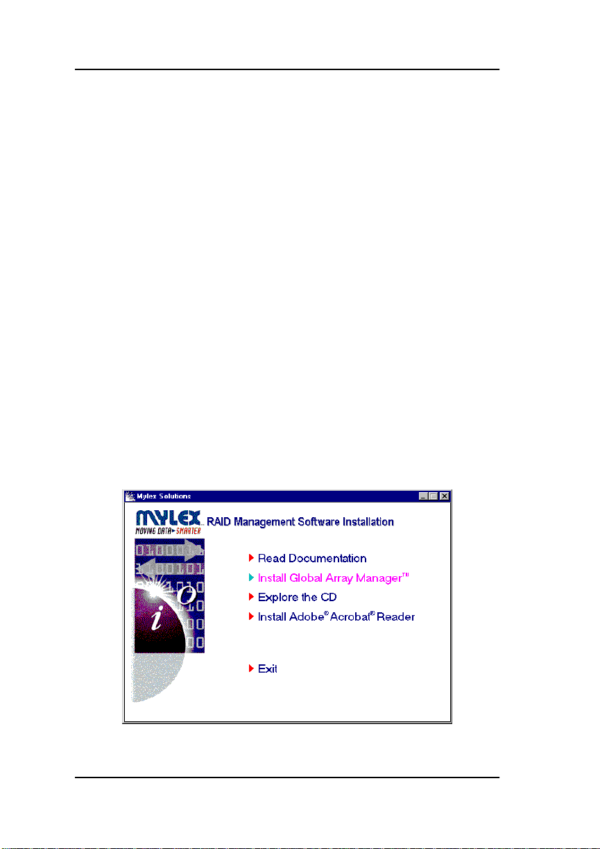
AutoRun will cause the CD-ROM to display the Mylex RAID
Management Software Installation menu (Figure 2-1).
Figure 2-1. Mylex RAID Management Software Installation Menu
2-2 GAM Client v2.21 and WSAM User’s Manual
Page 21
Installation
3. Click on the option called “Install Global Array Manager .” This option
is used to install GAM Server, GAM Client, or WSAM.
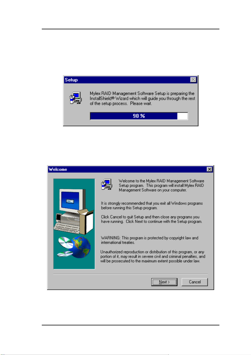
Mylex RAID Management Software Setup loads the installation wizard
(Figure 2-2):
Figure 2-2. Loading the Installation Wizard
4. After a few moments, the Welcome dialog box appears (Figure 2-3).
Click Next to proceed with the installation, or click Cancel to end the
installation procedure and return to the menu.
Figure 2-3. Welcome Dialog Box
Manual No. 771961 2-3
Page 22
Installation of Global Array Manager Client or Workstation Array Manager
5. Click Yes to accept the Mylex Software License Agreement.
☛Note
If you click No, you will not be allowed to continue
with software installation.
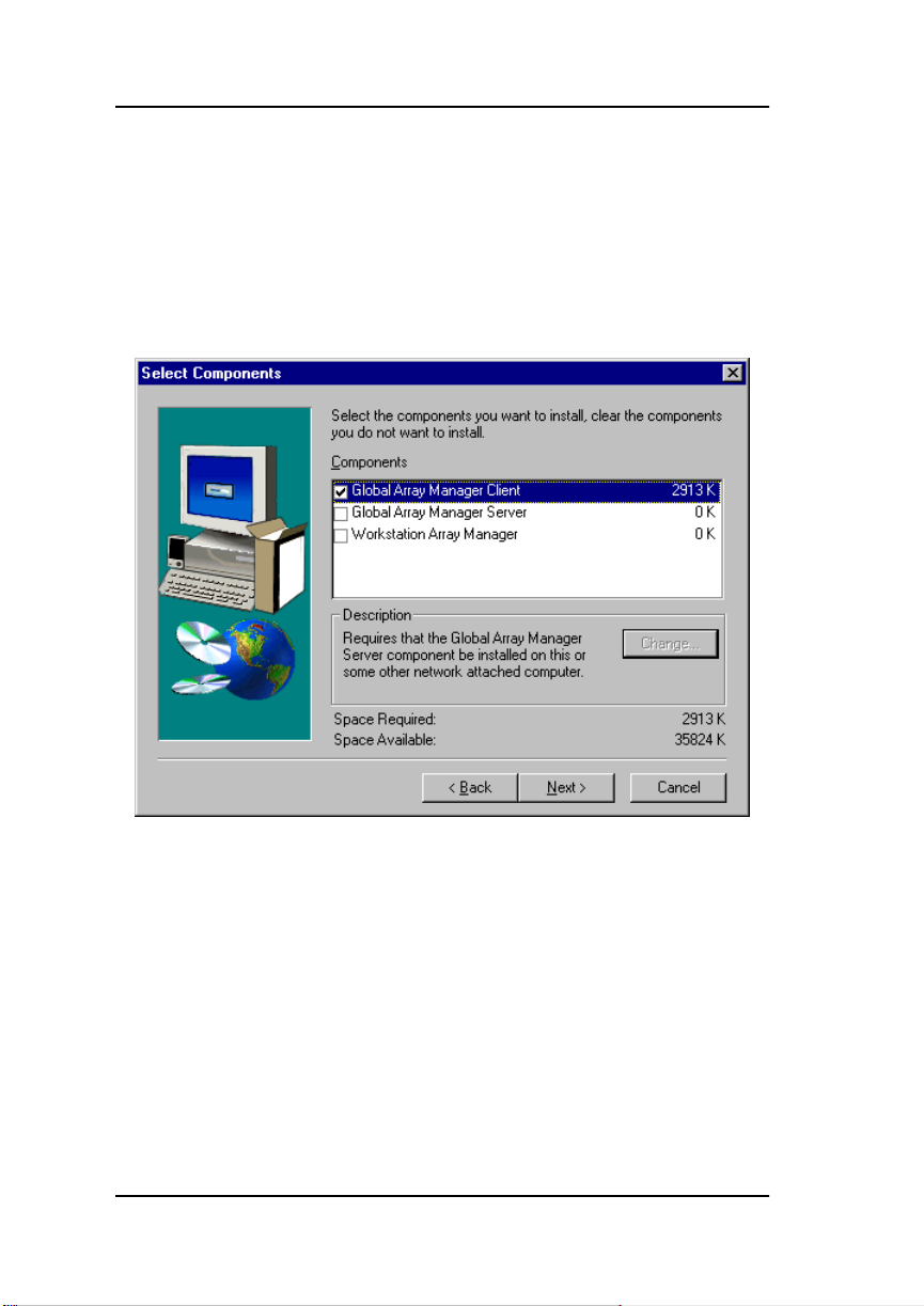
The Select Components dialog box is displayed as shown in Figure 2-4. At
this point you will select the component(s) you wish to install.
Figure 2-4. Select Components to Install
6. To select Global Array Manager Client for installation, click the box (if
necessary) to check the Global Array Manager Client option, OR
To select Workstation Array Manager for installation, click the box to
check the Workstation Array Manager option.
☛Note
If you check Global Array Manager Client, you may
also choose to install Global Array Manager Server at
this time. Instructions for GAM Server installation are
described in the Software Kit documentation.
2-4 GAM Client v2.21 and WSAM User’s Manual
Page 23
Installation
7. Click Next to continue with the installation once you’ve selected your
component(s).
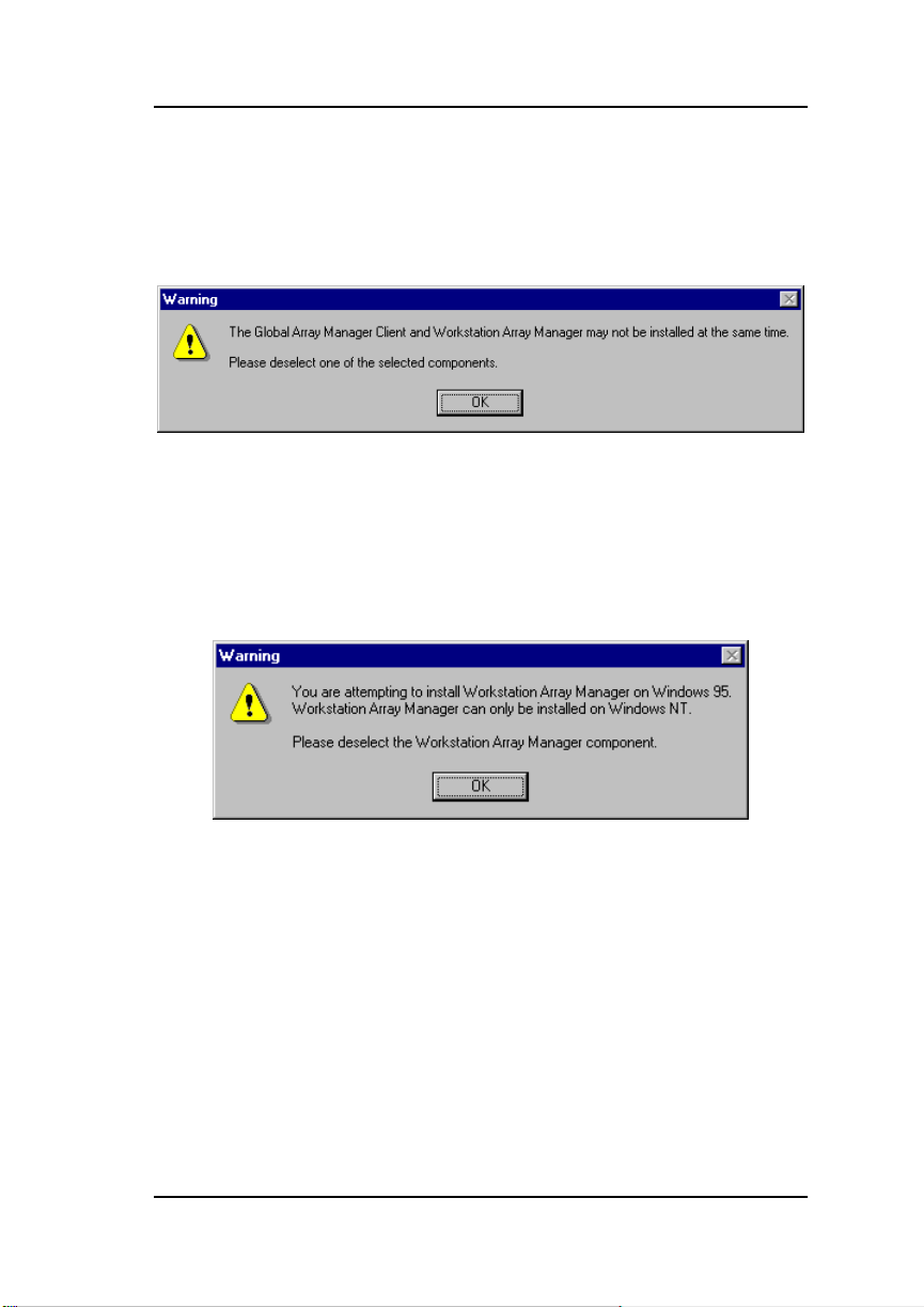
If you selected BOTH Global Array Manager Client AND Workstation
Array Manager, you will see the following message (Figure 2-5):
Figure 2-5. Error - Must Choose GAM Client OR WSAM
• If this message appears, click OK, then deselect either Global Array
Manager Client or Workstation Array Manager and click Next.
If you are attempting to install Workstation Array Manager under
Windows 95 or Windows 98, you will see the following message
(Figure 2-6):
Figure 2-6. Error - WSAM Must Be Installed Under Windows NT
• If this message appears, click OK, then deselect Workstation Array
Manager and click Next.
Manual No. 771961 2-5
Page 24
Installation of Global Array Manager Client or Workstation Array Manager
Global Array Manager Client Installation
If you’ve selected Workstation Array Manager, skip ahead to “Workstation
Array Manager Installation” on page 2-10.
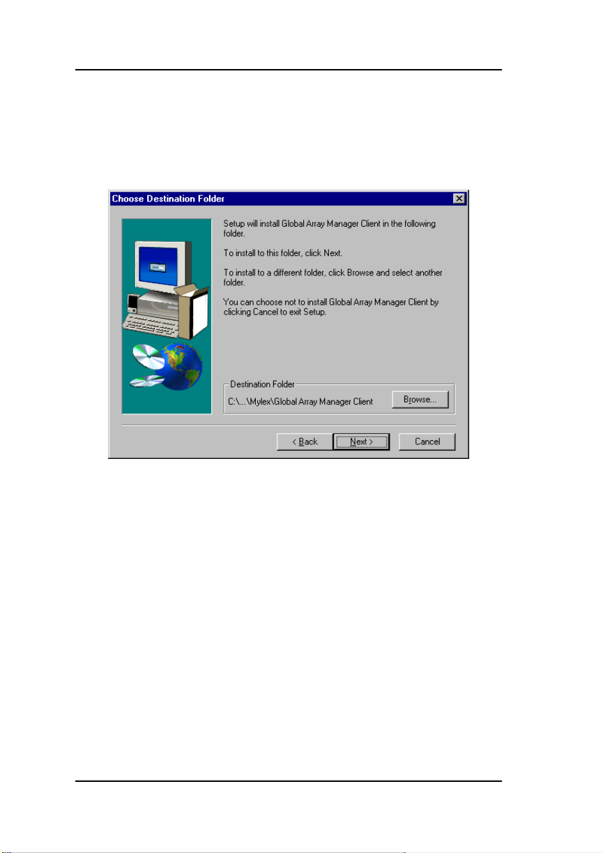
The Choose Destination Folder dialog box is displayed (Figure 2-7).
Figure 2-7. Destination Folder for Global Array Manager Client
1. In the Destination Folder area in Figure 2-7, the suggested directory
path for installation of GAM Client reads:
C:\Program Files\Mylex\Global Array Manager Client
• To select a different destination folder, click Browse, navigate to the
folder you wish to select, then accept it.
• To proceed with the installation, click Next.
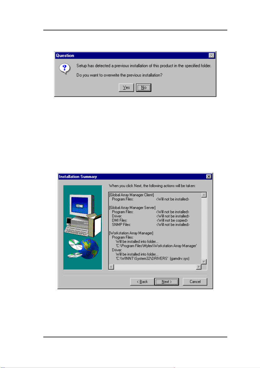
If Setup detects a previous installation of Global Array Manager Client
in the folder you specified, you will see the following message (Figure
2-8):
2-6 GAM Client v2.21 and WSAM User’s Manual
Page 25

Installation
Figure 2-8. Existing GAM Client Detected. Overwrite?
• If this message appears, click Yes to overwrite the existing GAM Client
installation, OR
• Click No to retain the existing GAM Client and select a new
destination folder for the new GAM Client, then click Next to proceed.
2. The Installation Summary screen (Figure 2-9) summarizes the
components and subcomponents you’ve selected for installation. Click
Next to continue or Back to change selected components.
Figure 2-9. Installation Summary
Manual No. 771961 2-7
Page 26
Installation of Global Array Manager Client or Workstation Array Manager
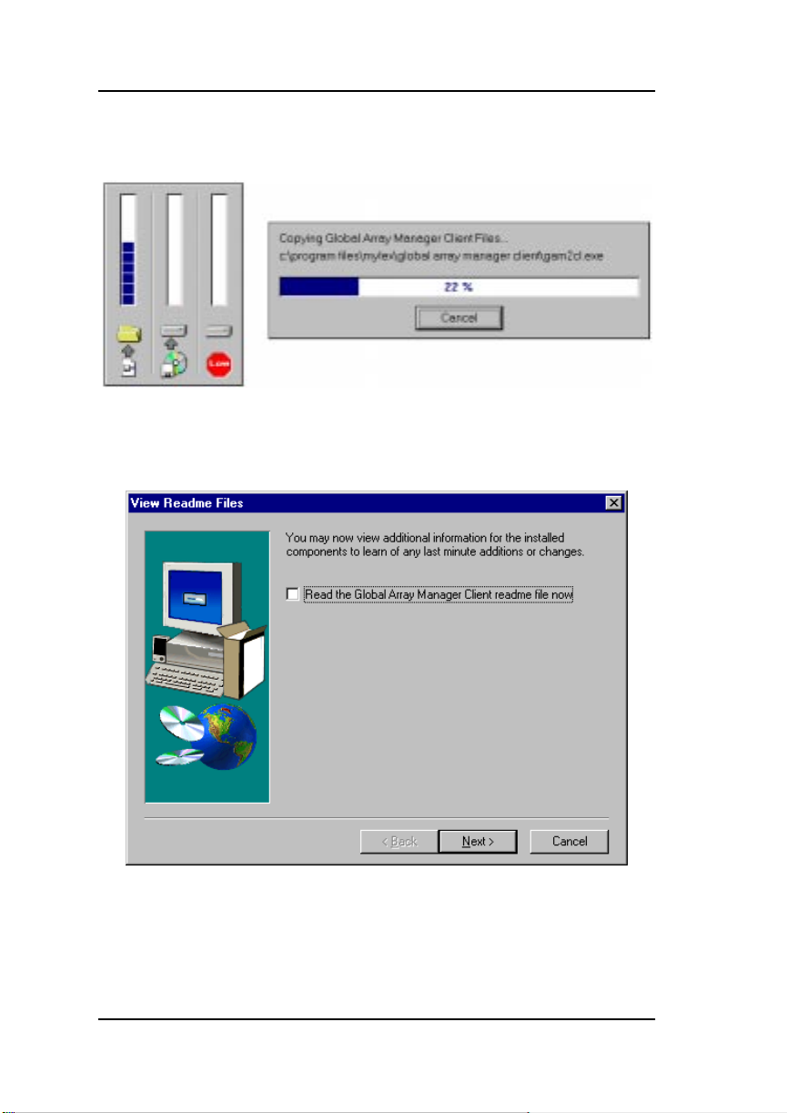
3. During installation, files are decompressed and copied from the
installation CD-ROM to the destination folder (Figure 2-10).
Figure 2-10. Installation Progress Display
Shortly after the installation completes, the following display appears
(Figure 2-11):
Figure 2-11. View ReadMe File(s)
If you also installed Global Array Manager Server, your screen will
display the names of both readme files.
2-8 GAM Client v2.21 and WSAM User’s Manual
Page 27
Installation
• To view changes and updates to the program or installation guide,
check the box which reads “Read the Global Array Manager Client
readme file now,” then click Next.
4. If you chose to view the ReadMe file, the Notepad accessory will open
and the file will be presented.
Read the contents of this file for the most up-to-date information about
Global Array Manager Client. Much of this information may not
appear in this installation guide, as sometimes last-minute
modifications to the software are done after completion of the guide.
You may also wish to print the contents of this file.
5. Close the Notepad accessory after reading and/or printing.
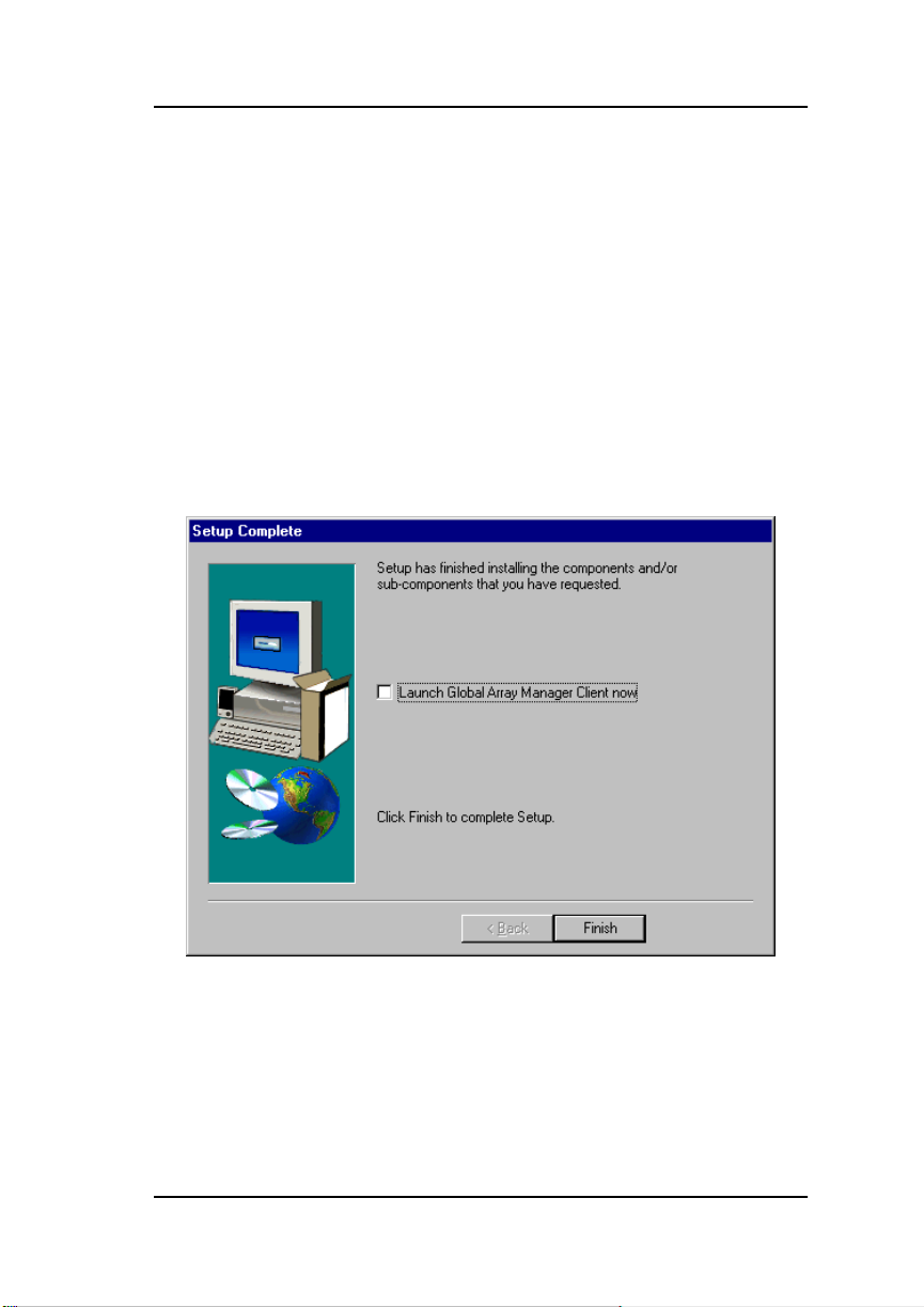
6. The Setup Complete dialog box displays (Figure 2-12):
Figure 2-12. Setup Complete. Launch GAM Client?
• If you want to launch Global Array Manager Client right after Setup,
click the box to check the “Launch Global Array Manager Client now”
option.
• Click Finish to complete Setup.
Manual No. 771961 2-9
Page 28

Installation of Global Array Manager Client or Workstation Array Manager
Workstation Array Manager Installation
The Choose Destination Folder dialog box is displayed (Figure 2-13).
Figure 2-13. Destination Folder for Workstation Array Manager
1. In the Destination Folder area in Figure 2-13, the suggested directory
path for installation of WSAM reads:
C:\Program Files\Mylex\Workstation Array Manager
• To select a different destination folder, click Browse, navigate to the
folder you wish to select, then accept it.
• To proceed with the installation, click Next.
If Setup detects a previous installation of Workstation Array Manager
in the folder you specified, you will see the following message (Figure
2-14):
2-10 GAM Client v2.21 and WSAM User’s Manual
Page 29
Installation
Figure 2-14. Existing WSAM Detected. Overwrite?
• If this message appears, click Yes to overwrite the existing WSAM
installation, OR
• Click No to retain the existing WSAM and select a new destination
folder for the new WSAM, then click Next to proceed.
2. The Installation Summary screen (Figure 2-15) summarizes the
components and subcomponents you’ve selected for installation. Click
Next to continue or Back to change selected components.
Figure 2-15. Installation Summary
Manual No. 771961 2-11
Page 30
Installation of Global Array Manager Client or Workstation Array Manager
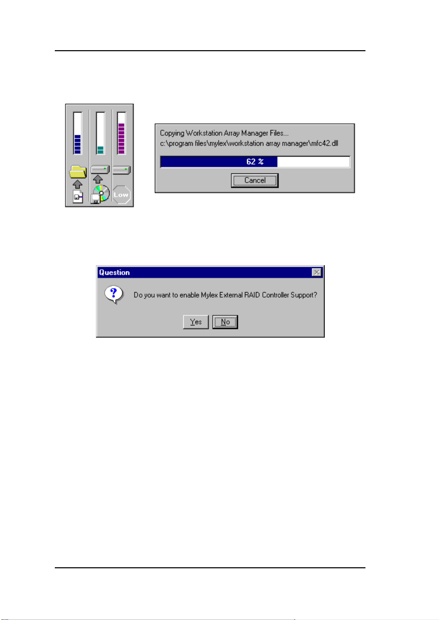
3. During installation, files are decompressed and copied from the
installation CD-ROM to the destination folder (Figure 2-16).
Figure 2-16. Installation Progress Display
4. After installation completes, the following message appears
(Figure 2-17):
Figure 2-17. Enable External RAID Controller Support?
• If you will be using Mylex External RAID Controllers, click Yes, OR
• If you will be using only Mylex PCI RAID Controllers, click No.
If you click Yes, Setup makes some minor adjustments in the GAM
configuration file to facilitate External RAID Controller operation.
2-12 GAM Client v2.21 and WSAM User’s Manual
Page 31

The following display appears (Figure 2-18):
Figure 2-18. View ReadMe File
5. To view changes and updates to the program or installation guide,
check the box which reads “Read the Workstation Array Manager
readme file now,” then click Next.
Installation
6. If you chose to view the ReadMe file, the Notepad accessory will open
and the file will be presented.
Read the contents of this file for the most up-to-date information about
Workstation Array Manager. Much of this information may not appear
in this installation guide, as sometimes last-minute modifications to the
software are done after completion of the guide. You may also wish to
print the contents of this file.
7. Close the Notepad accessory after reading and/or printing.
Manual No. 771961 2-13
Page 32

Installation of Global Array Manager Client or Workstation Array Manager
The Setup Complete dialog box displays (Figure 2-19):
Figure 2-19. Setup Complete. Restart the Computer?
8. You must restart the computer before using Workstation Array
Manager. Mak e sure that the “Yes, I want to restart my computer no w”
option is selected, then click Finish to complete Setup and reboot.
☛
Note
If you have other tasks to perform before rebooting
the system, you may instead select the “No, I will
restart my computer later” option. However, for
Workstation Array Manager to function properly, you
must implement a reboot before running WSAM for
the first time.
2-14 GAM Client v2.21 and WSAM User’s Manual
Page 33

Chapter 3
Startup & Navigation
Starting Global Array Manager or Workstation Array Manager
Server Component
☛Note
Installation and startup of the Global Array Manager
Server component 2.21 is covered in the Disk Array
Controller Software Kit Installation Guide and User
Manual, Mylex Part Number: 771929. The software
for GAM Server is provided on the installation CDROM.
Refer to the appropriate sections in the above-mentioned manual for
instructions on starting the Global Array Manager Server component under
any of the following network operating systems:
• NetWare 4.11/4.2 or 5.0
• Windows NT 4.0
• SCO OpenServer 5.0.4
• UnixWare 2.1.x or 7.0
Client Component
☛Note
Install and start the GAM Server component before
you attempt to run the GAM Client component.
Under Windows NT 4.0 or Windows 95/98, you are ready to start up the
Global Array Manager Client once you have installed the client on your
workstation (see the previous chapter).
Manual No. 771961 3-1
Page 34

Navigating Global Array Manager Client or Workstation Array Manager
• Start the GAM Client software (Start->Programs->Mylex Global
Array Manager Client). If at least one server group and file server are
defined, the opening screen appears. If not, the Define Server Groups
dialog box appears (see “Setting Up Server Groups and Servers” on
page 4-4).
Note
☛
After starting the Global Array Manager Client,
minimize the utility and let it run in the background at
all times, unless you’re doing a configuration or
setting up a maintenance process. If Global Array
Manager detects a logical drive in a critical state, or a
physical drive failing, it prompts you with windows
describing the location and nature of the problem.
Maximize the utility to display more detailed
information.
In order for event notification to occur the Global
Array Manager Server and Client must be running at
all times.
Workstation Array Manager Component
Under Windows NT 4.0, you are ready to start up the Workstation Array
Manager once you have installed this component on your workstation (see
the previous chapter).
• Start the WSAM software (Start->Programs->Mylex Workstation
Array Manager).
Navigating Global Array Manager Client or
Workstation Array Manager
Button Controls
Dialog boxes throughout the Global Array Manager Client and Workstation
Array Manager have a series of control buttons. Some examples of these
include:
3-2 GAM Client v2.21 and WSAM User’s Manual
Page 35

Startup & Navigation
Click this button to apply the settings made in the dialog box.
Click this button to cancel the settings made in the dialog box.
Click this button to confirm the action identified in the dialog
box.
Click this button to cancel the action identified in the dialog
box.
Click this button to close the activ e dialog box.
Click this button to apply your configuration changes.
Components of the GAM Opening Screen
Upon startup (with defined servers), Global Array Manager Client displays
the opening screen, consisting of the Global Array Manager window, the
Global Status View window and the Log Information Viewer (Figure 3-1).
#1
#2
#5 #6
Figure 3-1. Opening GAM Screen
Manual No. 771961 3-3
#7
#3
#4
Page 36

Navigating Global Array Manager Client or Workstation Array Manager
Components of the Global Array Manager Window
The major components of the Global Array Manager window (Figure 3-1)
are described below:
1. Item #1 is the GAM Client menubar. There are five menus with several
selections each. The contents of the menus and the functionality of
several of the most important selections will be described throughout
this guide.
2. Item #2 is the GAM Client toolbar. There are eight toolbar icons
representing eight of the most useful functions available in GAM
Client. The identity of each toolbar icon and an explanation of the
purpose of each will be described in later sections of this chapter.
3. Item #3 is the GAM Client server selection box. When selected, the
box displays the names of each server group that is in contact with the
current client workstation. Each group may consist of multiple servers.
You may select a specific server group to view, or select “All Servers”
if you want to view all the servers that are connected to this
workstation.
4. Item #4 is the GAM Client contr oller selection box. When selected, the
box displays the controller ID (C-0, C-1, etc.) and controller type (BT952, DAC960PJ, etc.) of each SCSI HBA and PCI/SCSI or External
RAID Controller connected to the currently-selected server. For
External RAID Controller duplex pairs, a double-pointed white arrow
connects the controller pair selections.
Components of the Global Status View Window
The major components of the Global Status View window (Figure 3-1) are
described below:
5. Item #5 is an icon that represents the currently-selected file server
running the GAM Server component. The icon identifies:
• the IP address (e.g. 192.192.200.5) or name (e.g. ide40) of the server
• the network operating system running on the server (e.g. SCO =
SCO OpenServer; NT = Windows NT; NW = Novell NetWare, etc.)
• the operational status of the server (green = functioning, yellow =
critical, red ‘X’ = down or nonfunctional)
3-4 GAM Client v2.21 and WSAM User’s Manual
Page 37

Startup & Navigation
• the number of DA C (PCI/SCSI or External RAID) controllers and/or
SCSI HBA controllers connected on the server, with a controller
operational status light (green = functioning, yellow = critical, red
‘X’ = down or nonfunctional)
6. Item #6 is an icon that represents a currently unselected file server
running the GAM Server component. The icon identifies the same
information described above under currently-selected file server.
Components of the Log Information Viewer
7. Item #7 in Figure 3-1 is the GAM Client Log Information Viewer. Each
line in the Log Information Viewer identifies a single event (error,
status, warning, etc.) which was noted during monitoring by a file
server running GAM Server, and was transmitted by that server to this
client workstation. Relevant details accompany the event:
• Event ID. Displays an icon showing whether the event is
informational, cautionary, a warning, etc., plus the identification
number assigned to this event
• Severity. The severity level of this event
• Source. The IP address or name of the file server that is the sender
(source) of this event
• Source Time. Day of the week, month, day of the month, time of
day, and year at the source file server’s location when this event
occurred
• Device Address. Relevant channel/target activity and other data
pertaining to why this event posted
• Description. Text of the message describing what occurred
• Sequence (Seq). Number representing where this event fell in a
sequence of possibly related events
• Local Time. Day of the week, month, day of the month, time of day ,
and year at the local client workstation’s location when this event
arrived.
Manual No. 771961 3-5
Page 38

Navigating Global Array Manager Client or Workstation Array Manager
Components of the WSAM Opening Screen
Upon startup, Workstation Array Manager displays the opening screen,
consisting of the Workstation Array Manager window, the Controller View
window and the Log Information Viewer (Figure 3-2).
#1
#2
#3 #4
#5
#6
Figure 3-2. Opening WSAM Screen
Components of the Workstation Array Manager Window
The major components of the Workstation Array Manager window (Figure
3-2) are described below:
1. Item #1 is the WSAM menubar. There are five menus with several
selections each. The contents of the menus and the functionality of
several of the most important selections will be described throughout
this guide.
2. Item #2 is the WSAM toolbar. There are eight toolbar icons
representing eight of the most useful functions available in WSAM.
The identity of each toolbar icon and an explanation of the purpose of
each will be described in later sections of this chapter.
3-6 GAM Client v2.21 and WSAM User’s Manual
Page 39

Startup & Navigation
3. Item #3 is the server selection box. Workstation Array Manager does
not allow access to remote servers, so this box is read-only and
contains the entry LOCAL_SERVER. The server selection box is used
only in GAM Client.
4. Item #4 is the WSAM controller selection box. When selected, the box
displays the controller ID (C-0, C-1, etc.) and controller type (BT-952,
DAC960PJ, etc.) of each SCSI HBA and PCI/SCSI or External RAID
Controller connected to the local server. For External RAID Controller
duplex pairs, a double-pointed white arr ow connects the contr oller pair
selections.
The Controller View Window
5. Item #5 in Figure 3-2 is the Controller View for the controller selected
in the controller selection box. WSAM opens with the controller view
of controller C-0 displayed by default. The controller view displays
controller channels, physical devices, and logical driv es. See Chapter 5
for additional information.
Components of the Log Information Viewer
6. Item #6 in Figure 3-2 is the WSAM Log Information Viewer. Each line
in the Log Information Viewer identifies a single event (error, status,
warning, etc.) which was noted during monitoring by the local server
and was transmitted to WSAM. Relevant details accompany the event:
• Event ID. Displays an icon showing whether the event is
informational, cautionary, a warning, etc., plus the identification
number assigned to this event
• Severity. The severity level of this event
• Source. The source is always the local server. This column is blank.
• Source Time. Day of the week, month, day of the month, time of
day, and year on the local server when this event occurred
• Device Address. Relevant channel/target activity and other data
pertaining to why this event posted
• Description. Text of the message describing what occurred
• Sequence (Seq). Number representing where this event fell in a
sequence of possibly related events
Manual No. 771961 3-7
Page 40

Navigating Global Array Manager Client or Workstation Array Manager
Menubar and Menus
GAM Client and WSAM contain a menubar (Figure 3-3) in the Global Array
Manager (or Workstation Array Manager) window:
Figure 3-3. Menu Bar
File Menu
Figure 3-4. File Menu
The File menu (Figure 3-4) contains the following options:
•
Open Configuration (Ctrl+O)
saves it to the controller. (See “Loading a Configuration from Disk” on
page 4-5).
•
Save Configuration (Ctrl+S)
filename, disk, and/or directory.
•
Clear Configuration
selected controller.
: Removes configuration information for the
: Loads a configuration from disk and
: Saves a configuration file to a new
m Caution
Although there are confirmation checkpoints and
warnings following selection of this option, remember
that all existing configuration and file data (on all
drives connected to the controller) will be deleted.
•
Exit (Ctrl+Q)
3-8 GAM Client v2.21 and WSAM User’s Manual
: Exits the GAM Client or WSAM.
Page 41

Startup & Navigation
View Menu
Figure 3-5. View Menu
The View menu (Figure 3-5) contains the following options:
•
Global Status View
: Toggles the Global Status View window (GAM
Client only). The Global Status View window opens by default when
Global Array Manager Client starts.
•
Controller View
: Toggles the Controller View window showing
channel/ID/target information and physical device/logical drive
configurations for the controller selected in the controller selection
box.
•
Statistics View
: Toggles the Statistics View window display for the
controller selected in the controller selection box.
•
Log Information Viewer
: Toggles the Log Information Viewer, a
window showing a log of recent system error and status event
messages. The Log Information Viewer opens by default when Global
Array Manager Client or Workstation Array Manager starts.
•
Initialize Status
: Displays the progress (percent complete) of an
ongoing full initialization of one or more drives.
Manual No. 771961 3-9
Page 42

Navigating Global Array Manager Client or Workstation Array Manager
• Rebuild Status: Displays the progress (percent complete) of an
ongoing device rebuild.
• Consistency Check Status: Displays the progress (percent complete)
of an ongoing logical drive consistency check.
• Expand Capacity Status: Displays the progress (percent complete) of
an ongoing data restriping process across the target RAID group.
m Caution
Once the Expand Array (Expand Capacity) process
has begun, you should not attempt to interrupt that
process before completion. Data loss will result. You
may, however, monitor the progress by choosing the
Expand Capacity Status option.
• Error Table: (PCI Only) Displays a table of bad block and “request
sense” data generated as a result of finding areas of damage or data
unavailability on a storage device. Data for all storage devices on the
selected controller are presented in the same tables.
3-10 GAM Client v2.21 and WSAM User’s Manual
Page 43

Administration Menu
Startup & Navigation
Figure 3-6. Administration Menu
The Administration menu (Figure 3-6) contains the following options:
•
Sign On
: Enables use of GAM’s or WSAM’s configuration and
administration functions to “Administrators” (“gamroot” + password).
Enables only monitoring functions to “Users.”
•
Define Server Groups
: (GAM Client only) Sets up server groups and
individual server names or IP addresses within each group.
•
Select Current Server Group (Ctrl+G)
: (GAM Client only) Displays
the current contents of the server selection box located in the Global
Array Manager window. Functions in the same way as directly
selecting the server selection box.
•
Select Current Controller (Ctrl+C)
: Displays the current contents of
the controller selection box located in the Global Array Manager or
Workstation Array Manager window. Functions in the same way as
directly selecting the controller selection box.
Manual No. 771961 3-11
Page 44

Navigating Global Array Manager Client or Workstation Array Manager
• RAID Assist: Mylex’s built-in RAID Controller configuration utility.
Facilitates configuration tasks using either one-step “automatic”
configuration, a configuration “wizard” assistant, or a manual
(advanced-level) configuration option allowing more control over
configuration parameters.
• Initialize Logical Drives: Offers the ability to run a full initialization
of logical drives at a time of your choice, NOT just immediately
following a new configuration. If it’s inconvenient to follow a
configuration immediately with a logical drive initialization, you can
decline the initialization and use this menu item to start the process at a
later time.
• Controller Information: Displays key information about the
currently-selected controller.
• Enclosure Information: Displays SES and SAF-TE Enclosure
Management information for Mylex External Fibre Channel
Controllers such as the DAC960FF.
• Controller Options: Sets various parameters for the selected Disk
Array Controller or SCSI HBA. Unlike Controller Information, user
definable controller parameters are modified in Controller Options.
• Intelligent BBU: (Only enabled if the selected controller has an
Intelligent Battery Backup Unit installed) Displays a dialog box from
which you can do the following:
• Monitor the power remaining in the Intelligent BBU
• Request reconditioning of the Intelligent BBU (External Controller
BBUs)
• Set the low power threshold
• Discharge the battery (External Controller BBUs)
The Intelligent BBU’ s features and functionality are described in detail
elsewhere. GAM/WSAM simply offer a way of keeping up-to-date as
to the condition and charge in the battery.
3-12 GAM Client v2.21 and WSAM User’s Manual
Page 45

Startup & Navigation
• Scan Devices: Scans for new de vices that hav e recently been added and
are not currently identified within GAM Client or WSAM.
• Advanced Functions: Opens a submenu (Figure 3-7) from which you
can select the following options:
• Performance Analysis: (PCI Controllers Only) Allows detailed
analysis of disk-level performance along several parameters.
• Flash Utility: Provides the ability to upgrade controller firmware as
new firmware maintenance releases become available.
• Shutdown: (External Controllers Only) Enable cleanl shutdown of
the controller system, leaving the battery charged.
Figure 3-7. Advanced Functions Submenu
• Settings: Opens a tabbed dialog box in which you can specify the
Alert/Alarm, Communication, and Event Editor settings that you
desire. Examples of such settings include type of alarm, such as pager,
fax, email, etc., modem baud rate, COM port, stop bits, data bits, parity ,
event severity level, event message editing, and so on.
Window Menu
Figure 3-8. Window Menu
Manual No. 771961 3-13
Page 46

Navigating Global Array Manager Client or Workstation Array Manager
The Window menu (Figure 3-8) is a standard feature of Windows 95 and
Windows NT. It is implemented as such in GAM/WSAM.
Help Menu
Figure 3-9. Help Menu
The Help menu (Figure 3-9) identifies the on-line help options available
within the Global Array Manager Client or Workstation Array Manager:
•
Contents
•
About Global Array Manager (or About Workstation Array
Manager)
: Displays a list of available help topics.
: Displays the Windows standard “About” box
.
Toolbar and Toolbar Icons
GAM Client and WSAM contain a toolbar (Figure 3-10) in the Global Array
Manager or Workstation Array Manager window:
Figure 3-10. Toolbar
Each toolbar button corresponds to a function available from the menu bar:
RAID Assist: Brings up the Raid Assist dialog
box for RAID controller configuration.
Scan Devices: Scans for new devices recently
added and not currently identified within GAM/
WSAM.
Display Controller Information: Displays key
information about the currently-selected DAC or
HBA.
3-14 GAM Client v2.21 and WSAM User’s Manual
Page 47

Startup & Navigation
Statistics View: Toggles the Statistics View
window for the currently-selected DAC or
HBA.
Error Table: Displays a table of bad block
and “request sense” data.
Sign On: Enables configuration and
administration functions to Administrators
and monitoring functions to “Users.”
Settings: Opens a dialog box for specifying
the Alert/Alarm, Communication, and Event
Editor settings that you desire.
Help: Displays the on-line help contents
page.
Exiting Global Array Manager or Workstation Array Manager
Exiting GAM Client or WSAM
Exit Global Array Manager Client or Workstation Array Manager as shown
in Figure 3-11:
Figure 3-11. Select “Exit”
☛
Note
We recommend leaving the GAM Client running as
long as there are servers you wish to monitor or
configure. If you do exit, you will be unable to receiv e
events from GAM Server and you will not be
informed of errors or status unless you restart GAM
Client and reconnect to the server(s).
Manual No. 771961 3-15
Page 48

For More Information...
Exiting GAM Server
Some operating systems (such as NetWare) allow you to “unload” the GAM
Server component while the file server remains running. Other operating
systems may require you to “down” the file server in order to exit from or
remove the GAM Server component.
m Caution
Be aware that downing a f i le serv er may result in data
loss if I/Os are in progress along the network. Exit the
GAM Server component only if necessary.
For More Information...
This concludes the Startup & Navigation chapter . F or additional information
on Global Array Manager or Workstation Array Manager options and
functionality, refer to other chapters in this installation guide, AND to the
context-sensitive online help file available from the Help menu, by pressing
F1, or by right-mouse-clicking an item on which you require help.
3-16 GAM Client v2.21 and WSAM User’s Manual
Page 49

Chapter 4
Configuration
Introduction
Configuration activities involve the following:
• Setting up server groups and servers (GAM Client only)
• Loading a configuration from disk and saving it to the controller
• Setting or modifying user preferences such as alarms, alerts, event
message editing, and communications parameters
• Setting or modifying controller options to suit your application needs
• Creating, modifying, or deleting Mylex RAID Controller
configurations
• Mapping LUNs (External RAID operation only)
Signing On to a Server
Security Access Levels
The ability to perform certain actions within the Global Array Manager
Client depends on your security access level.
There are three levels of security access, Guest (no sign-on), User, and
Administrator.
Guest
By attaching to a file server through the Global Array Manager Client, a user
is automatically assigned Guest (no sign-on) status. Guest users can monitor
Global status and the Log Information V ie wer. They cannot make changes to
any parameters or configurations.
User
A User has ordinary system privileges. A User signs on with his or her
username and a password that has been assigned by the Administrator of that
server. A User can alter parameters of anything that is not controller or drive
related, and also monitor the status of any selected controller and RAID
Manual No. 771961 4-1
Page 50

Signing On to a Server
subsystem, but has no administrative capability. The User cannot set up or
modify configurations, kill drives, rebuild drives, or change their on-line
status. In essence, Users can “look”, but they can’t “touch.”
Administrator
Individuals with Administrator security access have the capabilities of
Guests and Users plus the ability to manipulate controllers and RAID
subsystems. These additional abilities include configuration, drive kill, drive
rebuild, and drive state changes. An Administrator initially signs on as
“gamroot” and secures his or her access with a password.
Under Windows NT, the Global Array Manager uses security features built
into Windows NT.
Signing On
To gain access capabilities beyond Guest level, you must sign on to a server.
If you double-click a server from the Global Status View window when you
are not already signed on, then click on any option that requires
Administrator rights, the Sign On dialog box appears automatically (Figure
4-1).
Figure 4-1. Sign On Dialog Box
4-2 GAM Client v2.21 and WSAM User’s Manual
Page 51

Configuration
Open Sign On at any time as shown in Figure 4-2:
Figure 4-2. Select “Sign On”
Do the following:
1. Type the password previously enabled on the server that corresponds
with username “gamroot.”
This should provide Administrator access privileges.
2. Check the box labeled “Remember password for this session” if you
want GAM to refrain from Sign On messages each time you select a
server during this session which uses the same password. This amounts
to automatic sign-on on additional servers and should be used with
caution.
Uncheck the box if you want to retain the option of signing on to each
server you wish to access individually.
3. Click the Sign-On button.
Manual No. 771961 4-3
Page 52

Setting Up Server Groups and Servers
Setting Up Server Groups and Servers
Adding a Server Group to the Server Group List
Open Define Server Groups as shown in Figure 4-3:
Figure 4-3. Select “Define Server Groups”
Figure 4-4. Define Server Groups Dialog Box
In the Define Server Groups dialog box (Figure 4-4), do the following:
1. Click the Add button under the Server Groups section of the dialog
box.
2. In the Adding Item dialog box, enter a name for the server group that
you are adding.
4-4 GAM Client v2.21 and WSAM User’s Manual
Page 53

Configuration
3. Click OK. The Define Server Groups dialog box will reappear with the
newly-defined serv er group added.
Adding a Server to the Servers List
With the Define Server Groups dialog box open (Figure 4-4), do the
following:
1. Click the Add button under the Servers section of the dialog box.
2. In the Adding Item dialog box, enter the IP address of the server that
you are adding. If you’re running GAM Client under Windows NT, you
may instead enter the name of the server.
3. Click OK. The Define Server Groups dialog box will reappear with the
newly-defined serv er added.
4. To add more servers to the group, repeat steps 1 through 3.
5. Click OK in the Define Server Groups dialog box when you are
finished.
After adding servers, Global Array Manager returns to the Global Status
window.
☛Note
Select “All Servers” to see all servers in the Global
Status view.
Loading a Configuration from Disk
Load a previously-saved configuration from disk as shown in Figure 4-5
Figure 4-5. Select “Open Configuration”
Manual No. 771961 4-5
Page 54

Loading a Configuration from Disk
1. In the Open Configuration dialog box (Figure 4-6), select the
configuration file you wish to open to save to the controller.
Figure 4-6. Open Configuration Dialog Box
2. Click Open to access the configuration file.
A window displays key elements of the configuration you are about to
open (Figure 4-7).
Figure 4-7. Stored Configuration Information to be Opened
4-6 GAM Client v2.21 and WSAM User’s Manual
Page 55

Configuration
3. Click Apply to apply the configuration to the controller , or click Cancel
to stop without applying the saved configuration.
If you click apply, you will be asked to confirm your decision to
overwrite the existing configuration.
Setting and Modifying User Preferences
Open Settings as shown in Figure 4-8:
Figure 4-8. Select “Settings”
Manual No. 771961 4-7
Page 56

Setting and Modifying User Preferences
Alert Preferences
Figure 4-9. Settings Dialog Box: Alert Preferences
In the Settings dialog box, under the Alert Preferences tab (Figure 4-9), you
have the option to do any of the following:
Event Log
• Append events to your current log file, or
• Replace the log file (overwrite it)
• Rename the log file
• Enable or disable the event logging function
Enable Global Alerts for Severity Level(s)
• For each type of alarm (Email, Pager, Fax, Launch Application, and
Alarm Sound) check the box(es) corresponding to the event severity
level(s) for which you would like to enable this type of alarm globally.
For example, in Figure 4-9, all Level 0 and Level 1 messages/events
will result in an alarm sound locally, and email, page (Level 0 only),
and fax to those individuals identified in Alarm Setup.
4-8 GAM Client v2.21 and WSAM User’s Manual
Page 57

Configuration
Events are numbered from 0 for most severe to 4 for least severe, and
can be edited by the user.
Finish by doing one of the following:
• Click OK to accept the global alert settings and exit the Settings dialog
box, or
Click Cancel to leave original settings unchanged, or
Click another Settings tab to set additional user preferences.
Alarm Setup
Figure 4-10. Settings Dialog Box: Alarm Setup
The top half of the Alarm Setup dialog box lists the types of alarms that can
be used (Pager, Fax, Email, Launch Application). The lower half of the
Alarm Setup dialog box lists the currently defined destinations/recipients/
applications for the alarm type selected in the upper window (Figure 4-10).
Add a Pager
1. Select the Pager alarm type in the upper window.
2. Click Add.
The Pager setup box is displayed as shown in Figure 4-11:
Manual No. 771961 4-9
Page 58

Setting and Modifying User Preferences
Figure 4-11. Pager Setup Dialog Box
3. In the Pager box:
• Enable or disable this Pager entry using the Enabled check box.
• Enter the Modem Setup String, or keep the default.
• Enter a Pager Prefix, or keep the default.
• Enter the phone number of someone who will receive a page.
• Enter a Pager Suffix if needed.
• Enter a Pager Delay interval. The value of each comma is 1 second.
• Enter the Modem Hangup String, or keep the default.
☛
Note
Please consult your modem manufacturer or modem
documentation for the specific string which works
best with your modem.
• Select the appropriate button for a Numeric or Alphanumeric pager.
4. If you need to enter a Message Prefix, Suffix, or Delay interval, click
Advanced. Enter the desired information and click OK to return to the
Pager setup box.
4-10 GAM Client v2.21 and WSAM User’s Manual
Page 59

Configuration
5. To test the pager using the settings you’ve input, click Test.
6. When you are satisfied with the Pager you’ve set up, click OK.
Your new Pager entry appears in the lower window of the Alarm Setup
dialog box. (Refer back to Figure 4-10 for an example.)
Remove a Pager
1. Select the Pager alarm type in the upper window of Alarm Setup.
2. Select the Pager entry to remove in the lower window of Alarm Setup.
3. Click Remove.
A confirmation message is displayed as shown in Figure 4-12:
Figure 4-12. Remove Pager Entry Message
4. Click Yes to remove the Pager entry, or click Cancel to keep the entry.
Manual No. 771961 4-11
Page 60

Setting and Modifying User Preferences
Add a Fax
1. Select the Fax alarm type in the upper window of the Alarm Setup
dialog box (Figure 4-13).
Figure 4-13. Fax Alarm Setup
2. Click Add.
The Fax setup box is displayed as shown in Figure 4-14:
Figure 4-14. Fax Setup Dialog Box
3. In the Fax box:
• Enable or disable this Fax entry using the Enabled check box.
4-12 GAM Client v2.21 and WSAM User’s Manual
Page 61

• Enter the fax phone number of someone who will receive a fax.
• Enter a fax header, if desired.
☛Note
For fax notification Microsoft Exchange and
Microsoft At Work Fax software must be installed on
your system. GAM supports only Microsoft At Work
Fax under Windows 95. The Software field is not
selectable.
The required fax software components should already
be available as part of the normal Windows 95
installation.
4. To test the fax using the settings you’ve input, click Test.
5. When you are satisfied with the Fax you’ve set up, click OK.
Your new Fax entry appears in the lower window of the Alarm Setup
dialog box. (Refer back to Figure 4-13 for an example.)
Remove a Fax
1. Select the Fax alarm type in the upper window of Alarm Setup.
Configuration
2. Select the Fax entry to remove in the lower window of Alarm Setup.
3. Click Remove.
4. At the confirmation message, click Yes to remove the Fax entry, or
click Cancel to keep the entry.
Manual No. 771961 4-13
Page 62

Setting and Modifying User Preferences
Add Email
1. Select the Email alarm type in the upper window of the Alarm Setup
dialog box (Figure 4-15).
Figure 4-15. Email Alarm Setup
2. Click Add.
The Email setup box is displayed as shown in Figure 4-16:
Figure 4-16. Email Setup Dialog Box
3. In the Email box:
• Enable or disable this Email entry using the Enabled check box.
• Enter the email address of someone who will receive an email.
4-14 GAM Client v2.21 and WSAM User’s Manual
Page 63

Configuration
• Enter the subject of the email.
4. To test the email using the settings you’ve input, click Test.
5. When you are satisfied with the Email you’ve set up, click OK.
Your new Email entry appears in the lower window of the Alarm Setup
dialog box. (Refer back to Figure 4-15 for an example.)
Remove Email
1. Select the Email alarm type in the upper window of Alarm Setup.
2. Select the Email entry to remove in the lower window of Alarm Setup.
3. Click Remove.
4. At the confirmation message, click Yes to remove the Email entry, or
click Cancel to keep the entry.
Add an Application to Launch
1. Select the Launch Application alarm type in the upper window of the
Alarm Setup dialog box (Figure 4-17).
Figure 4-17. Launch Application Alarm Setup
2. Click Add.
Manual No. 771961 4-15
Page 64

Setting and Modifying User Preferences
The Launch Application setup box is displayed as shown in
Figure 4-18:
Figure 4-18. Launch Application Setup Dialog Box
3. In the Launch Application box:
• Enable or disable this Application entry using the Enabled check
box.
• Enable Launch Only Once if you want to prevent the application
from launching again if GAM detects that it is already running.
• Enter the name of an application to launch should certain events or
messages require it.
• If you don’t remember the name or path of the application, click the
Browse button.
4. To test the application launch using the settings you’ve input, click
Test.
5. When you are satisfied with the application you’ve set up, click OK.
Your new application entry appears in the lower window of the Alarm
Setup dialog box. (Refer back to Figure 4-17 for an example.)
Remove an Application to Launch
1. Select the Launch Application alarm type in the upper window of
Alarm Setup.
2. Select the Launch Application entry to remove in the lower window of
Alarm Setup.
3. Click Remove.
4-16 GAM Client v2.21 and WSAM User’s Manual
Page 65

Configuration
4. At the confirmation message, click Yes to remove the application entry,
or click Cancel to keep the entry.
Properties
For any of the four alarm types (Pager, Fax, Email, Application), you may
view a particular entry’s settings by selecting an entry in the lower window
of Alarm Setup and clicking Properties.
Communication
Figure 4-19. Settings Dialog Box: Communication
In the Settings dialog box, under the Communication tab (Figure 4-19), you
have the option to change any of the following:
Baud Rate
• Select the baud rate appropriate to your communication hardware.
Port
• Select the COM port at which your communication hardware resides.
Parity
• Select the type of parity for communication sessions: None, Even, Odd,
Manual No. 771961 4-17
Page 66

Setting and Modifying User Preferences
Mark, Space.
Stop Bits
• Select the number of stop bits required for communication sessions: 1,
1.5, 2.
Data Bits
• Select the number of data bits required for communication sessions: 4,
5, 6, 7, 8.
Finish by doing one of the following:
• Click OK to accept the communication settings and exit the Settings
dialog box, or
Click Cancel to leave original settings unchanged, or
Click another Settings tab to set additional user preferences.
Event Editor
Figure 4-20. Settings Dialog Box: Event Editor
In the Settings dialog box, under the Event Editor tab (Figure 4-20), you
have the option to do any of the following:
4-18 GAM Client v2.21 and WSAM User’s Manual
Page 67

Configuration
GAM ID / User Event/ Severity / Default
• Select a GAM (event) ID to edit from the GAM ID list box.
• Enter your own number for this event in the User Event list box, or
keep the default (equal to the GAM ID number).
• Enter your own event severity le vel in the Severity list box, or keep the
default (set by Mylex).
• Click the Default button to return all settings for this particular ev ent to
their Mylex defaults.
Alarm for the Event
• When all Global boxes are checked, you are seeing the alarms that will
activate when this particular event occurs (these are based on the
settings in Alert Preferences). Check or uncheck specific boxes if you
wish to override these defaults and change the alarms for this event.
Event Message Text
• Enter new text for this event, or keep the default text (set by Mylex).
Default All
• Click the Default All button to reset all ev ents of all sev erity le vels back
to their Mylex defaults.
Finish by doing one of the following:
• Click OK to accept the event settings and exit the Settings dialog box,
or
Click Cancel to leave original settings unchanged, or
Click another Settings tab to set additional user preferences.
Manual No. 771961 4-19
Page 68

Setting and Modifying Controller Options
Setting and Modifying Controller Options
Open Controller Options as shown in Figure 4-21:
Figure 4-21. Select “Controller Options”
Mylex PCI RAID Controllers
Figure 4-22. Controller Options Dialog Box For PCI DAC
☛
Note
You can not change controller options if the controller
is running Mylex PCI firmware version 3.x or below!
4-20 GAM Client v2.21 and WSAM User’s Manual
Page 69

Configuration
In the Controller Options dialog box (Figure 4-22), you have the option to do
any of the following:
• Enable (by checking) or disable (by unchecking) any of the following
Global Parameters:
• Automatic Rebuild Management. Works in conjunction with SAF-
TE disk array enclosures to detect removal of a failed drive and
perform an automatic rebuild after installation of a replacement
drive.
• Active Negation. Recommended for cleaner SCSI signal transitions.
• Read Ahead. Reads data to the next stripe boundary (based on stripe
size) and retains in cache any data beyond the size of the actual read
request.
• Disconnect On First Command. Allows target to disconnect from
initiator.
• Background Initialization. Allows logical drive initialization to
take place “behind the scenes” so that the logical drive is
immediately available for use. If you disable this option, logical
drives will need to complete their initialization process before they
can be used.
• Change the default Rebuild Rate to less than or equal to 50.
A rate of 50 devotes the maximum allowable resources to a drive
rebuild or array expansion, allowing the Rebuild or Expand to proceed
at its fastest. Lowering the number devotes more resources to I/Os and
consequently slows the Rebuild or Expand Array process.
• Change any of the following Startup Parameters:
• Spin-up. Change if you do not want automatic drive spin-up.
• Devices Between Spins. Number of devices to spin up at one time.
A low number lessens the likelihood of a power drain.
• Initial Delay . Number of seconds between ph ysical device start-ups.
• Sequential Delay. Number of seconds between consecutive device
spin-up cycles.
• Change any of the following SCSI Parameters (note that Transfer
Speed is read only):
Manual No. 771961 4-21
Page 70

Setting and Modifying Controller Options
• Channel for this controller
• Whether the controller will handle data at 8-bit or 16-bit transfers
• Maximum data transfer rate of the disk side channels. Speeds are
Asynchronous, 5 MHz, 8 MHz, 10 MHz, 20 MHz, and 40 MHz
(LVD only).
• SCSI Tag Queuing. Enable in order to queue up commands to be
executed by the target.
• Enable (by checking) or disable (by unchecking) the following
Clustering Parameter:
• Clustering. Under Windows NT 4.0, allows redundancy among
controllers in various servers. If a controller or server fails, another
controller can take over the disk drives and disk arrays that were
formerly handled by the failed controller. This mechanism imparts a
“fault tolerance” among controllers and servers.
• Change the following Clustering Parameter:
• Controller Host ID. Change if you want to set this controller’s
target ID to something other than 7.
Click the OK button to accept the changes, or the Cancel button to delete
them.
4-22 GAM Client v2.21 and WSAM User’s Manual
Page 71

Configuration
Mylex External RAID Controllers
Figure 4-23. Controller Options Dialog Box For External DAC
In the Controller Options dialog box (Figure 4-23), you have the option to do
any of the following:
• Enable (by checking) or disable (by unchecking) any of the following
Global Parameters:
•
Automatic Rebuild Management
TE disk array enclosures to detect removal of a failed drive and
perform an automatic rebuild after installation of a replacement
drive. Do not disable this unless you are sure of the consequences.
. Works in conjunction with SAF-
•
Active Negation
•
Read Ahead
•
Disconnect On First Command
. Not available for External RAID Controllers.
. Not available for External RAID Controllers.
. Not available for External RAID
Controllers.
•
Background Initialization
. Not used on External RAID
Controllers.
• Change the default Rebuild Rate to less than or equal to 50.
A rate of 50 devotes the maximum allowable resources to a drive
rebuild or array expansion, allowing the Rebuild or Expand to proceed
Manual No. 771961 4-23
Page 72

Setting and Modifying Controller Options
at its fastest. Lowering the number devotes more resources to I/Os and
consequently slows the Rebuild or Expand Array process.
• Change any of the following Startup Parameters:
• Spin-up. Change if you do not want automatic drive spin-up. Other
choices are to spin up at power on, or to wait for a command and
then do an automatic drive spin-up.
• Devices Between Spins. Number of devices to spin up at one time.
A low number lessens the likelihood of a power drain.
• Initial Delay . Number of seconds to wait before spinning up the f irst
disk set.
• Sequential Delay. Number of seconds between consecutive device
spin-up cycles.
• Change any of the following SCSI Parameters (note that Transfer
Speed is not changeable):
• Channel selects the channel to be viewed for the current data.
• Whether the channel will negotiate 8-bit or 16-bit transfers
• Maximum data transfer rate of the disk side channels. Speeds are
Asynchronous, 5 MHz, 8 MHz, 10 MHz, 20 MHz, and 40 MHz
(LVD only).
Note
☛
SCSI Parameters are disabled for Fibre back-end
products such as the DAC960FF.
Note
☛
Clustering Parameters are not used on External RAID
Controllers.
4-24 GAM Client v2.21 and WSAM User’s Manual
Page 73

Configuration
Advanced Controller Options (All External RAID Controllers)
Click the Advanced button in the Controller Options dialog box to inspect
and/or change additional External RAID Controller Options.
Figure 4-24. Advanced Controller Options Dialog Box
In the Advanced Controller Options dialog box (Figure 4-24), you have the
option to do any of the following:
• Set the following limits:
•
Queue Limit
. Maximum allowed queue depth for tagged commands
to each attached drive. Settings are from 1 (no tags) to 230.
•
MAXIOPs Limit
. Sets maximum number of IOP structures allowed
for controller command operations, limiting the number of
simultaneous commands. Settings are from 64 to 244.
• Enable (by checking) or disable (by unchecking) any of the following
options:
•
Conservative Cache Mode
. Turns off write cache while a failover
condition persists, allowing an extra degree of data safety.
•
SAF-TE Use of UPS
. Enables monitoring of uninterruptable power
supply if it is also supported by the system enclosure.
•
Restrict Reassign to One Block
. Restricts a reassign to the failing
block. If disabled, reassigns will be for the entire current I/O blocks,
Manual No. 771961 4-25
Page 74

Setting and Modifying Controller Options
not all of them failing.
• Smart Large Host Transfers. For transfers larger than the stripe
size, allows selection of Coalesce (fewer disconnects) on host data
transfers.
• Elevator Ordering Of Device Queues. Attempts to keep the drive
heads moving in the same direction as long as possible to improve
performance. Assumes LBAs are physically sequentially ordered.
• Coalesce Device Queues. Joins data from adjacent I/Os into a single
I/O to improve performance.
• Super Read Ahead (SRA). Extends the Read Ahead process by
always reading an extra cache line on a read request, and reading an
additional cache line when a cache hit occurs. Most useful for
applications where read-sequential data is high.
• True Verification Of Data. Performs a true verify with data
comparison.
• Write Through Verify. During error handling, this turns on Force
Unit Access for reads and writes.
• Operational Fault Management. Allows the controller to take
autonomous actions when a failure occurs. Do not disable this
function unless specifically instructed to do so as part of a
troubleshooting diagnostic activity.
• Disable (by checking) or enable (by unchecking) the following option:
• Wide Transfer On Host. When disabled, the controller will
negotiate only narrow data transfers. Doing this unnecessarily will
result in slower performance.
4-26 GAM Client v2.21 and WSAM User’s Manual
Page 75

Configuration
Expert Controller Options (All External RAID Controllers)
Click the Expert button in the Advanced Controller Options dialog box to
inspect and/or change expert-level External RAID Controller Options. These
options should remain at their defaults unless you have a high degree of
expertise with External RAID Controller Options.
Figure 4-25. Expert Controller Options Dialog Box
In the Expert Controller Options dialog box (Figure 4-25), you have the
option to do any of the following:
• Enable (by checking) or disable (by unchecking) any of the following
options:
•
Simplex No RSTCOM
. Allows a controller not to assert a reset
signal to its partner controller. Simplex environments only.
•
Left Symmetric RAID5 Algorithm
. Changes a Right Symmetric
RAID 5 parity scheme to Left Symmetric. This item is available
only when there are no logical drives defined.
•
On Q Full Give Busy
. When a command is received and the
controller detects a full queue, it will return a “busy” status rather
than Queue Full. This helps hosts that do not accurately deal with
Manual No. 771961 4-27
Page 76

Setting and Modifying Controller Options
Queue Full status.
• Vendor Unique Test Unit Ready Status. Enables a vendor unique
TUR effect. A TUR sent to an offline LUN will get a hard error
status returned.
• No Pause On Controller Not Ready. When the controller is not
fully started, certain commands encounter a pause. This turns off the
pause.
• Auto Restore. Allows the surviving controller to automatically
sense and place an inserted replacement controller back in service.
Controller Present/Fault Signals must be enabled.
• Force Simplex. Allows duplex firmware to work in a simplex
environment by skipping some Active-Active operations.
• Reset Propagation. Allows a port that executes an internal reset to
cause a reset event to occur on its attached interface.
• Multi-port Reset. Allows execution of an internal reset on a port
only if a logical drive has been reserved through that port.
• Controller Present/Fault Signals. (DAC960SX only.) Informs a
controller that certain signals should be used to detect the presence
or absence of a partner controller.
• Disable (by checking) or enable (by unchecking) the following option:
• CC For Invalid LUN. Disables the check condition, affecting the
handling of the Inquiry command when the referenced LUN is
invalid.
• Set the Host Bus Reset Delay. Allo ws the controller to reset the host in
failover and failback situations. When Disabled - no SCSI bus reset is
generated on the host; 1 - 14 - generates reset this many seconds after
the failover or failback occurs; Immediate - generates immediate reset
with no delay. This is host SCSI only.
• Set Debug Port Usage. Select SLP/VT100 emulation or Debug mode.
• Set Debug Port Speed. Sets the baud rate for the serial port from 2400
to 19200 baud.
4-28 GAM Client v2.21 and WSAM User’s Manual
Page 77

Configuration
Fibre Controller Options (External Fibre Controllers Only)
The Fibre button only displays in the Controller Options dialog box when a
Mylex Fibre Channel RAID Controller is currently selected.
Click the Fibre button in the Controller Options dialog box to inspect and/or
change Fibre options for External Fibre RAID Controllers. These options
should remain at their defaults unless you have a high degree of expertise
with External Fibre RAID Controllers.
Figure 4-26. Fibre Controller Options Dialog Box
In the Fibre Controller Options dialog box (Figure 4-26), you have the
option to do any of the following:
• Enable/Disable
Node Name Retention
. When enabled, each controller
shares its node name with its partner controller, and those names are
used through all phases of failover and failback.
• Set
Hard Loop IDs
for each controller and port combination. Enable a
controller/port combination by checking its check box. Values allow
use of the same Loop IDs all the time. Some Fibre HBAs work better
with this.
• Set
PCI Latency Control
Manual No. 771961 4-29
. Controls the amount of data each Front end
Page 78

Setting and Modifying Controller Options
Fibre Protocol Processor can burst across the primary PCI bus before
relinquishing bus ownership. Settings are Short, Medium, Long. A
setting of Long is recommended.
• Set Frame Control. Allows adjustment of the FC chip’s frame size.
• Set Topology of the controller. (1) requires two ports on each
controller, one acti ve, one inactive. The active port is for normal traffic,
the inactive port is for the partner’s traffic after failover. (2) configures
the controller pair for master/slave operation. Other options are
currently undefined.
Recording Your Changes
Click OK in the Advanced Controller Options, Expert Controller Options,
and/or Fibre Controller Options dialog boxes to accept the changes, or the
Cancel button to delete them.
SCSI Host Bus Adapters
Figure 4-27. Controller Options Dialog Box For SCSI HBA
In the Controller Options dialog box (Figure 4-27), you have the option to do
any of the following:
4-30 GAM Client v2.21 and WSAM User’s Manual
Page 79

Configuration
• Enable (by checking) or disable (by unchecking) the following SCSI
Device Parameters:
• Wide Negotiation. Allows the controller to negotiate at wide data
transfer rates.
• Disconnect. Allows the target to disconnect from the initiator.
• Change the SCSI ID of this HBA.
• Change either of the following Startup Parameters:
• Spin-up. No Spin up, Controller spin up.
• Delay. Number of seconds before physical device startup.
• Change the following SCSI Device Parameter:
• Maximum data transfer rate of the disk side channels. Speeds are
Asynchronous, 5 MHz, 10 MHz, and 20 MHz.
Click the OK button to accept the changes, or the Cancel button to delete
them.
Manual No. 771961 4-31
Page 80

Running RAID Assist
Running RAID Assist
RAID Assist is the Global Array Manager Client’s “wizard” for the setup
and configuration of new logical drives and disk arrays.
In its simplest form, RAID Assist provides an Auto Configuration option
which immediately configures all available drives into an optimal, RAID 5
configuration. RAID Assist’s Assisted Configuration sets up a new array
according to predefined parameters, and asks the user questions to gather the
key information necessary to build the array.
If configuration needs go beyond what Auto or Assisted Configuration
offers, the Manual Configur ation option allows additional control over
logical drive setup parameters, including LUN Mapping for External RAID
Controllers.
Entering RAID Assist
Open RAID Assist as shown in Figure 4-28:
Figure 4-28. Select “RAID Assist”
4-32 GAM Client v2.21 and WSAM User’s Manual
Page 81

Configuration
Figure 4-29. RAID Assist “Welcome” Dialog Box
In the RAID Assist “Welcome” dialog box (Figure 4-29), do one of the
following:
• Click the Automatic Configuration button if you want to provide only
minimal input and allow RAID Assist to set up an optimal
configuration automatically, or
• Click the Assisted Configuration button if you want RAID Assist to
lead you step-by-step through the configuration, or
• Click the Manual Configuration button if you want full control over
your configuration setup, or
• Click Cancel if you want to exit RAID Assist without any changes.
Manual No. 771961 4-33
Page 82

Running RAID Assist
Automatic Configuration
Automatic Configuration provides three options:
• New Configuration. Sets up a new configuration on the controller,
deleting the previous configuration and data (if any).
• Add Logical Drive. Sets up additional arrays (logical drives) leaving
the existing array(s) intact. At least one array must be configured on
this controller, and unconfigured drive space must remain.
• Expand Array. Restripes data in your array across additional,
unconfigured drives to expand the capacity of the array.
Open New Configuration (for example), as shown in Figure 4-30:
Figure 4-30. Select “New Configuration”
4-34 GAM Client v2.21 and WSAM User’s Manual
Page 83

Figure 4-31. Automatic Configuration->New Configuration->Finish
The Finish screen appears (Figure 4-31). Do the following:
1. Examine the Configuration Summary for details about the
configuration that RAID Assist will set up.
Configuration
2. If you want to start over, click the Back or Cancel button, OR
If you want to view the configuration before it is applied to the
controller, click the Details button. You will be taken to an equivalent
of the Disk Arrays page as shown in Manual Configuration, ex cept that
you can only view and close the details window.
3. If you accept the configuration as presented, click the Apply button at
the Finish page to apply the new configuration to the controller.
A warning confirmation box appears as shown in Figure 4-32:
Manual No. 771961 4-35
Page 84

Running RAID Assist
Figure 4-32. WARNING Before Applying the Configuration
4. Type
configuration and overwrite the old. If you’re not sure, click Cancel.
and click OK if you are sure you want to apply the new
YES
☛
Note
In Automatic Configuration, Add Logical Drive and
Expand Array function very similarly to the New
Configuration option. In each case RAID Assist
prepares an optimal configuration without user input
based on characteristics of the available devices.
4-36 GAM Client v2.21 and WSAM User’s Manual
Page 85

Configuration
Assisted Configuration
Assisted Configuration provides three options:
• New Configuration. Sets up a new configuration on the controller,
deleting the previous configuration and data (if any).
• Add Logical Drive. Sets up additional arrays (logical drives) leaving
the existing array(s) intact. At least one array must be configured on
this controller, and unconfigured drive space must remain.
• Expand Array. Restripes data in your array across additional,
unconfigured drives to expand the capacity of the array.
Open New Configuration (for example), as shown in Figure 4-33:
Figure 4-33. Select “New Configuration”
Manual No. 771961 4-37
Page 86

Running RAID Assist
Assisted Configuration walks you step by step through a new configuration
(Figure 4-34). Each “tab” in the Assisted Configuration dialog box collects
information about an important aspect of the configuration you wish to set
up. During this process, you provide answers to several questions.
Fault Tolerance Tab (Figure 4-34)
1. Do you want Fault Tolerance? [Yes/No]
2. Do you want a Hot Spare? [Yes/No]
Figure 4-34. Assisted Configuration - Fault Tolerance
4-38 GAM Client v2.21 and WSAM User’s Manual
Page 87

Configuration
RAID Level Tab (If Fault Tolerance Was Yes) (Figure 4-35)
3. Choose between:
• Parity error correction (RAID 5, RAID 3), or
• Fully redundant drives (RAID 1, RAID 0+1)
Figure 4-35. Assisted Configuration - RAID Level With Fault Tolerance
Manual No. 771961 4-39
Page 88

Running RAID Assist
RAID Level Tab (If Fault Tolerance Was No) (Figure 4-36)
4. Choose between:
• Striping (RAID 0), or
• Stand-alone drive (JBOD)
Figure 4-36. Assisted Configuration - RAID Level With No Fault Tolerance
4-40 GAM Client v2.21 and WSAM User’s Manual
Page 89

Configuration
Logical Drives Tab (Figure 4-37)
5. How many logical drives do you want to create? [1 - 32 for PCI]
[1 - 8 for External]
6. How much capacity do you want to use? [default=100% available
space, or equivalent in MB]
7. Do you want to initialize logical drives? [Yes/No]
This is done after the configuration has been applied.
Figure 4-37. Assisted Configuration - Logical Drives
Certain Mylex PCI RAID Controllers allow Immediate RAID Availability of
logical drives after configuration. For these controllers, initialization can
take place in the background without the need to wait for full foreground
initialization. If you selected Yes to the question above and the controller
supports background initialization, the following screen will appear (Figure
4-38):
Manual No. 771961 4-41
Page 90

Running RAID Assist
Figure 4-38. Background Initialization is Supported
8. If this message appears, click Yes to request a full foreground
initialization of logical drives once the new configuration is applied,
OR
Click No to take advantage of the background initialization support.
Once you’ve applied your configuration, your logical drives will be
available for immediate use.
4-42 GAM Client v2.21 and WSAM User’s Manual
Page 91

Optimization Tab (Figure 4-39)
9. Choose between:
• write cache enabled (write back), or
• write cache disabled (write through)
10. Select Stripe Size (valid options are in the list)
11. Select Cache line size: [see below]
Valid cache line size values depend on the stripe size setting and are
listed appropriately once you’ve selected a stripe size.
Configuration
Figure 4-39. Assisted Configuration - Optimization
Manual No. 771961 4-43
Page 92

Running RAID Assist
Figure 4-40. Assisted Configuration->New Configuration->Finish
When you get to the Finish screen (Figure 4-40), do the following:
1. Examine the Configuration Summary for details about the
configuration that RAID Assist will set up.
2. If you want to start over, click the Welcome tab or Cancel button, OR
If you want to change your answers to any of the questions you were
asked, click the appropriate tab to return to that screen, OR
If you want to view the configuration before it is applied to the
controller, click the Details button. You will be taken to an equivalent
of the Disk Arrays page as shown in Manual Configuration, except that
you can only view and close the details window.
3. If you accept the configuration as presented, click the Apply button at
the Finish page to apply the new configuration to the controller.
A warning confirmation box appears as shown in Figure 4-41:
4-44 GAM Client v2.21 and WSAM User’s Manual
Page 93

Configuration
Figure 4-41. WARNING Before Applying the Configuration
4. Type
configuration and overwrite the old. If you’re not sure, click Cancel.
and click OK if you are sure you want to apply the new
YES
☛
Note
In Assisted Configuration, Add Logical Drive and
Expand Array function very similarly to the New
Configuration option. In each case RAID Assist leads
you step-by-step through the relev ant questions for the
task.
Manual Configuration
Manual Configuration provides four options:
•
Edit Configuration
and logical drives), and allows you to make any changes that you
require.
•
New Configuration
deleting the previous configuration and data (if any).
•
Add Logical Drive
the existing array(s) intact. At least one array must be configured on
this controller, and unconfigured drive space must remain.
•
Expand Array
unconfigured drives to expand the capacity of the array.
. Displays the current configuration (disk arrays
. Sets up a new configuration on the controller,
. Sets up additional arrays (logical drives) leaving
. Restripes data in your array across additional,
Manual No. 771961 4-45
Page 94

Running RAID Assist
Open New Configuration (for example), as shown in Figure 4-42:
Figure 4-42. Select “New Configuration”
Figure 4-43. Manual Configuration - Disk Arrays
The Disk Arrays tab in Manual Configuration is where you begin to
configure your unused disk drives (lower left, Figure 4-43). Each disk array
is represented by one line in the Disk Arrays area of the screen (upper left,
4-46 GAM Client v2.21 and WSAM User’s Manual
Page 95

Configuration
Figure 4-43). Logical drives (if any have already been configured) appear on
the right side.
☛Note
For External RAID Controllers, there will be a fourth
tab called “4. LUN Mapping.” The Apply button for
External RAID Controller configuration resides on
the LUN Mapping page. See “LUN Mapping in
Global Array Manager” on page 4-52 for more
information.
Do the following:
1. Select an unused drive and drag it to the Disk Array A0 section. The
drive will be part of a disk array referred to as “A0.”
2. Select other unused drives and drag them to Disk Array A0, OR click
the Add Array button to create a row for Disk Array A1 (then A2, A3,
etc.), then drag unused drives to A1 if you so desire.
3. If you want to manually configure a hot spare, click an unused drive,
then click the Make Spare button.
4. If you want to start over, click the Clear All button and start again.
Manual No. 771961 4-47
Page 96

Running RAID Assist
5. Once you’ ve assembled the disk array groups, click the Logical Drives
tab to continue on to logical drive setup (Figure 4-44):
Figure 4-44. Manual Configuration - Logical Drives
The Logical Drives tab in Manual Configuration is where you conf igure your
disk arrays into logical drives. Your first logical drive will set the stripe size
and cache line size for all logical drives on this controller.
Do the following:
1. Select a RAID level for your f irst logical drive. Supported RAID levels
are RAID 0, RAID 1, RAID 3, RAID 5, RAID 0+1, and stand-alone
drive (JBOD). Only RAID levels compatible with the current
configuration will be available in the list.
2. Enter the amount of available logical or physical capacity for this
logical drive. If your total configuration will have only one logical
drive which uses all available capacity, the default sizes should not be
changed. If you intend to create additional logical drives now or later,
enter a smaller number to reserve the desired amount of capacity.
3. Check the Write Cache box if you want this logical drive to use Write
Back caching. This improves performance but puts data at risk. You
should have a battery backup unit or uninterruptable power supply if
selecting this feature.
4-48 GAM Client v2.21 and WSAM User’s Manual
Page 97

Configuration
4. Check the Init Drive box if you want this logical drive to be fully
initialized at the conclusion of the configuration. It is recommended
that you check this option (if available), unless the controller is capable
of background initialization. If so and you check the box, you’ll see a
message when you apply the configuration indicating that you can
make use of the background initialization support.
5. If this is your first logical drive, select a stripe size. This setting will
apply to all logical drives on this controller.
6. If this is your first logical drive, select a cache line size. Available
settings will depend on the selected stripe size. (Not available for
External RAID Controllers.)
7. Click the Add Drive button to register your new logical drive.
8. If you are configuring a Mylex PCI RAID Controller, click Apply to
save the configuration if you are finished setting up logical drives, OR
Repeat the process above to set up additional logical drives, then click
Apply when you’re done.
If you are configuring a Mylex External RAID Controller, click the
LUN Mapping tab to continue with configuration (see “LUN Mapping
in Global Array Manager” on page 4-52), OR
Repeat the process above to set up additional logical drives, then click
the LUN Mapping tab when you’re done.
An example of a completed Manual configuration is shown in Figure 4-45:
Manual No. 771961 4-49
Page 98

Running RAID Assist
Figure 4-45. Sample Manual Configuration Just Before “Apply”
☛
Note
In Manual Configuration, Add Logical Drive and
Expand Array function very similarly to what was
shown above. In each of these two cases, however,
RAID Assist shows you the disk arrays and logical
drives and allows you to add to the configuration
without risking existing data.
4-50 GAM Client v2.21 and WSAM User’s Manual
Page 99

Configuration
External RAID Controller Operation Overview
External RAID Controllers use their host ports to connect to one or more
Host Bus Adapters in one or more host computer systems.
Depending on the model and configuration of the controller, there may be
from one to four host ports. Each configured logical drive consumes a
particular bus-target ID-LUN on the host system. Multiple sets of disk dri ves
are connected to the controller via its drive channels. There may be as many
as six drive channels, depending on the controller model and configuration.
In duplex, or Active/Active mode, two identical External RAID Controllers
are connected to the same hosts via their host ports, to the same drives via
their drive channels, and to each other via a special hardware link for
heartbeat sensing. This forms a redundant controller system. The two
controllers work together handling data traffic and mirror their write data in
each other’s cache memory. If one of the controllers fails or otherwise
becomes non-operational, the surviving controller takes over its
responsibilities with no loss of data.
☛Note
This section presents only a brief introduction to
External RAID Controller operation. For additional
details, consult the hardware installation guide for the
particular controller of interest.
LUN Mapping Overview
External RAID Controller LUN Mapping allows logical drives (or system
drives) to be made available or unavailable on one or more host ports. The
mapping is performed by assigning Logical Unit Numbers (LUNs) to logical
drives. The LUN assignments are per host port and are independent of the
assignments on other host ports. Logical drives may be assigned only one
LUN per host port.
By not assigning a LUN to a logical drive on a particular host port, that
logical drive is made inaccessible to that host port.
Manual No. 771961 4-51
Page 100

External RAID Controller Operation Overview
LUN Mapping in Global Array Manager
Global Array Manager implements LUN Mapping by allowing the user to
map Logical Unit Numbers (LUNs) to specific controller/port combinations.
After configuring the desired number of logical driv es on the Mylex External
RAID Controller, click the LUN Mapping tab in Manual Configuration
(Figure 4-46). (The Controller-Port columns are shown or not shown
depending on the current controller configuration of host ports and duplex
controllers.) By default these logical drives are made a vailable to all existing
host ports in the configuration. LUNs are assigned automatically in
sequential order for each port.
Figure 4-46. Select “LUN Mapping”
,
WARNING
If Global Array Manager Server is running under
Windows NT, be sure to assign each logical drive to
a specific, individual port (not to all ports). When
logical drives are available to ALL host ports,
Windows NT may assign multiple volumes (e.g. C:
and E:) to the same physical media. Data
corruption and/or data loss can result.
4-52 GAM Client v2.21 and WSAM User’s Manual
 Loading...