

Page 1

AcceleRAID™
Quick Installation Guide
AcceleRAID 150
AcceleRAID 200
AcceleRAID 250
PCI to Ultra2 SCSI
RAID Controllers
P/N: 775030-00
Page 2

Page 3

AcceleRAID
™
Quick Installation Guide
AcceleRAID 150
AcceleRAID 200
AcceleRAID 250
PCI to Ultra2 SCSI
RAID Controllers
Part Number 775030-00
© Copyright 1999 Mylex Corporation.
All Rights Reserved.
All contents of this manual are copyrighted by Mylex
Corporation. The information contained herein is the
exclusive property of Mylex Corporation and shall not be
copied, transferred, photocopied, translated on paper, film,
electronic media, or computer-readable form; or otherwise
reproduced in any way, without the express written
permission of Mylex C orporation.
Page 4

Greetings
Thank you for purchasing the Mylex AcceleRAID™ 150/200/250 controller. This manual
describes the installation of the Mylex AcceleRAID controllers. Requests for technical
information ab out this and other Mylex Corporation products should be made to your
Mylex authorized reseller or Mylex sales representative.
Please Notice
Mylex is a registered trademark, and AcceleRAID, DAC960PRL, and DAC960PTL are a
trademarks of Mylex Corporation.
Microsoft, MS-DOS and Windows are registered trademarks of the Micr osoft
Corporation. Novell is a registere d t ra demark of Novell corporation. LSI and Symbios
Logic are registered t rademarks of LSI Logi c C orporation. Other names that are
trademarks may be used herein for the purpose of identifying the products or services of
their respective owners. Unless otherwise noted, companies, names and data used in
examples herein ar e ficti tious.
Our Policy
Although reason able efforts have been made to assure the accuracy of the inf o r m ation
contained herein, this publication could include technical inaccuracies or typographical
errors. Mylex Corporation expressly disclaims liability for any error in this information,
and for damages, w hether direct, indirec t, spe cial, exemplary, consequential or otherwi se,
that may result from such error, including but not limited to loss of profits resulting from
the use or misuse of the manual or information contained therein (even if Mylex
Corporation has been advised of the possibility of such damages). Any questions or
comments regarding this document or its contents should be addressed to Mylex
Corporation at the address shown on the cover.
The following paragraph does not apply to the United Kingdom or any country where such
provision s are inco n sistent with local l aw:
MYLEX CORPORATION PROVIDES THIS PUBLICATION “AS IS” WITHOUT
WARRANTY OF ANY KIND, EITHER EXPRESS OR IMPLIED, INCLUDING, BUT
NOT LIMITED TO, THE IMPLIED WARRANTIES OF MERCHANTABILITY OR
FITNESS FOR A PARTICULAR PURPOSE.
Some states do not allow disclaimer of express or implied warranties or the limitation or
exclusion of liability for indirect, special, exemplary, incidental or consequential damages
in certain transactions; therefore, this statement may not apply to you. Also, you may have
other rig hts which vary from jurisdiction to ju risdiction.
Information in this publication is subject to change without notice and does not represent a
commitment on the part of Mylex Corporation. Changes may be made periodically to the
information herein; th ese changes will be incorpora ted in new editions of the publ ic ation.
Mylex Corporatio n re serves the righ t to make i mpro v ement s and/ or ch ang es a t an y t ime in
the product(s) and/or program(s) described in this publication.
It is possible that this publication may contain reference to, or information about, Mylex
Corporation products (machines and programs), programming or services that are not
announced in your country. Such references or information must not be construed to mean
that Mylex Corporation intends to announce, provide, or make available such Mylex
products, programming, or services in your jurisdiction.
Page 5
Regulatory Information
The AcceleRAID 150, 200, and 250 comply with the following regulatory
agencies:
Federal Communications Commission
The FCC information statements are in Appendix C of the AcceleR AID 15 0
Installation Guide (P/N 775024) and Appendix C of the AcceleRAID 200
and 250 Installation Guide (P/N 775007).
Community of Europe
The CE information statements are in Appendix C of the AcceleRAID 150
Installation Guide (P/N 775024) and Appendix C of the AcceleRAID 200 and
250 Installation Guide (P/N 77500 7).
Underwriters Laboratories
,
WARNING
This controller is furnished with a nonvolatile
RAM (NVRAM) chip that uses a sealed lithium
battery/crystal module. Replace the module only
with the same or equivalent type recommended by
the manufacturer. Dispose of the used battery/
crystal module according to the manufacturer's
instructions. Never incinerate a battery as it could
explode and cause serious injury.
Page 6

Table of Contents
Hardware
Introduction – Assumptions ..................................................................1
Types of Installations ............................................................................1
Standard Installation ......................................................................1
SCSI Interrupt Steering Logic (SISL) Installation ..........................1
Performing a Standard Installation .......................................................2
Performing a SCSI Interrupt Steering Logic (SISL) Installation ............6
RAID Configuration
Using RAID EzAssist ..........................................................................11
Operating Systems and Drivers
NetWare .............................................................................................14
Installing the Mylex Disk Array Controller as the
Primary NetWare 4.11/4.2 Controller ..........................................14
Installing the Mylex Disk Array Controller into an
Existing NetWare 4.11/4.2 System ..............................................15
Overview of NetWare 5.0 ....................................................................17
Mylex Disk Array Controller Driver Files for NetWare ................. 17
Tape and CD-ROM Support ........................................................17
Mylex Disk Array Controller Driver for
NetWare 5.0 .......................................................................................18
Installing the Mylex Disk Array Controller as the
Primary NetWare 5.0 Controller ..................................................18
Installing the Mylex Disk Array Controller into an
Existing NetWare 5.0 System ......................................................21
Windows NT ................................................................................ ...... .23
Installing the Mylex Disk Array Controller as the
Primary Windows NT 4.x Controller ............................................23
Installing the Mylex Disk Array Controller into an
Existing Windows NT 4.x System ................................................25
Manual No. 775030 iv
Page 7

Hardware
Introduction – Assumptions
The AcceleRAID 150, AcceleRAID 200 and the AcceleRAID 250 are very
versatile Ultra2 SCSI, LVD RAID controllers. There are literally thousands
of possible hardware configurations. In order to keep this Quick Installation
Guide down to a manageable size, the following assumptions are being
made:
• A RAID 0, 1, or 5 installation is being installed.
• The user is familiar with Windows NT
• The user is familiar with disk drive and RAID terminology.
Types of Installations
There are two types of installations:
• Standard Installation
• SCSI Interrupt Steering Logic (SISL) Installation
Standard Installation
In a standard installation, the AcceleRAID 150 or the AcceleRAID 250
functions as a single-channel, standard PCI to Ultra2 SCSI, LVD RAID
controller. In a standard installation, the AcceleRAID 150 or 250 can be
installed into any system board with an available PCI (2.1 compliant) slot.
®
or Novell® NetWare®.
SCSI Interrupt Steering Logic (SISL) Installation
In a SISL installation, the AcceleRAID 200 adds RAID functionality to a
system board that has one or more embedded SCSI channels. The
AcceleRAID 150 or 250 adds an Ultra2 SCSI, LVD RAID channel as well as
RAID functionality to a system board that has one or more embedded SCSI
channels. For a SISL implementation, the AcceleRAID controllers must be
plugged into a special, pre-wired PCI slot in a system board that is specially
designed for this type of installation. Check with the ma nufacturer of your
system board to find out if it has embedded SCSI channels that can be
controlled by a PCI to SCSI RAID controller with SCSI Interrupt Steering
Logic (a requirement for the AcceleRAID 200).
Manual No. 775030 1
Page 8
Performing a Standard Installation
Performing a Standard Installation
(AcceleRAID 150 and AcceleRAID 250 only)
m Caution
If an operating system or existing data resides on
SCSI disk drives already installed on the system, a
full backup should be performed on these drives prior
to this installation.
1. Be sure power is turned off and the system is not plugged into an
electrical outlet.
,
WARNING
To avoid electrical shock, do not attempt to
perform this hardware installation with power on.
Disconnect the system from the electrical wall
outlet.
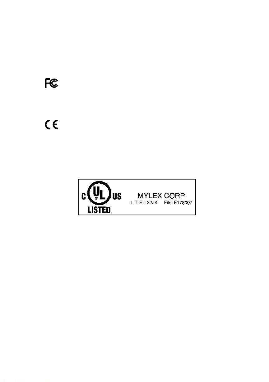
2. If JP10 on the AcceleRAID 150 or 250 is install ed, remo ve i t, as sho wn
in Figure 1 and in Figure 2.
J2
External
Connector
(VHDCI)
J1
Internal Connector
(68-Pin High Density)
JP1U1SE
LVD
JP4
JP5
12
Jumperon Jumperoff
3
Jumper removed and
placed over a single
pin for safekeeping
JP10
Note: J1 and J2 are both on the same Channel.
Figure 1. AcceleRAID 150 with Component Locations
Table 1. AcceleRAID 150 Jumpers and LEDs
Jumpers Description LEDs Description
JP1 Header for SCSI activity LED
(Pin 1 – active low, Pin 2 – Vcc)
JP4 Mylex use only LVD LVD mode on unless SE device
JP5 Not used
JP10 Off for standard – On for SISL SE Single-ended device detected
2 AcceleRAID 150/200/250 Quick Installation Guide
U1 On – controller failed startup diags.
detected.
Page 9
Hardware
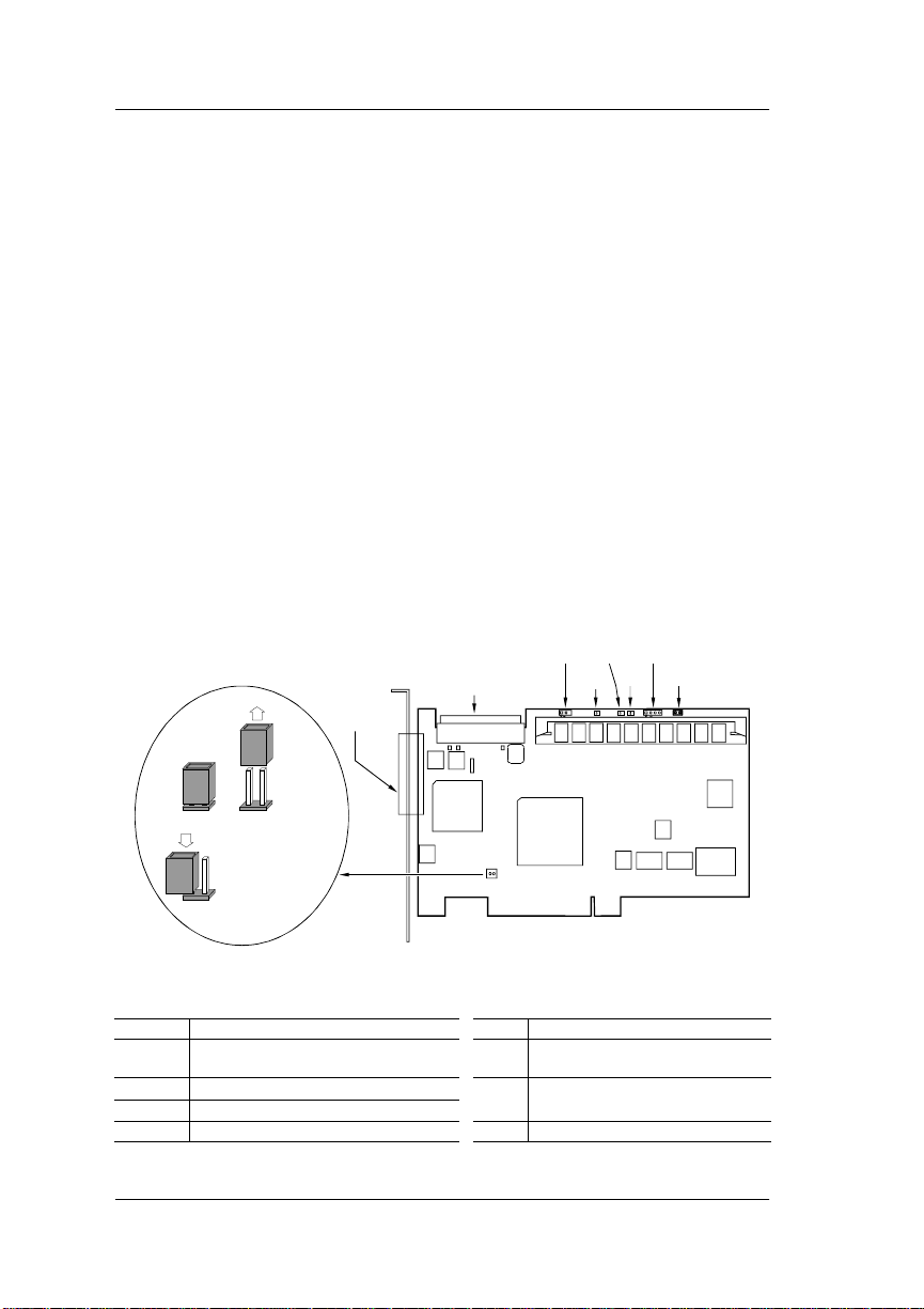
J
12
Jumper on Jumper off
3
Jumper removed and
placed over a single
pin for safekeeping
Figure 2. AcceleRAID 250 with Component Locations
Jumpers Description
JP10 Off for standard – On for SISL
Figure 3. Pinout for JP1 on the AcceleRAID 250
1
J2
External
Connector
(VHDCI)
Internal Connector
(68-Pin High Density)
JP10
Note: J1 and J2 are both on the same Channel.
JP1
Table 2. AcceleRAID 250 Jumpers
JP1 Header for SCSI activity & Cache Dirty LEDs
JP4 Mylex use only
JP5 Not used
CC
V
JP1,
LED
Connector
Channel
Activity
LED*
Cache
Dirty
LED*
*Activelow
JP4
JP5
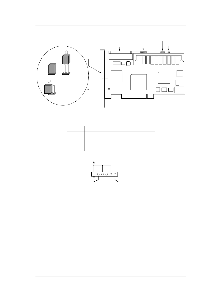
3. Plug the AcceleRAID 150 or 250 card into an available PCI slot (see
Figure 4).
Manual No. 775030 3
Page 10
Performing a Standard Installation
SystemBoard
Plug Controller into
any Available PCI
Slot
Figure 4. .Plugging the AcceleRAID 150 or 250 into a Standard PCI Slot
4. Set the SCSI ID on each internal drive to a unique address between 0
and 15, but do not u se address 7, as it is reserved for the con troller. See
the documentation that comes with you r drives for instructions on how
to do this.
m Caution
If internal and external driv es are used, be sure that no
drive addresses are duplicated. External SCSI cabinets
usually automatically assign drive addresses
according to where in the cabinet the drives are
located.
5. Be sure termination is disabled on all drives connected to the
controller. See the documentation that comes with your drives for
instructions on how to do this.
6. Be sure that termination power is enabled on all dri ves co nnected to the
controller. See the documentation that comes with your drives for
instructions on how to do this.
7. Connect a wide, high-density, 68-pin SCSI ribbon cable to the internal
SCSI connector on the AcceleRAID 150 or 250 and connect the other
cable connectors to any internal SCSI drives as required. See Figure 5.
8. Connect an active terminator to the end of the SCSI ribbon cab le at the
end farthest from the controller. See Figure 5.
4 AcceleRAID 150/200/250 Quick Installation Guide
Page 11
Hardware
T
T
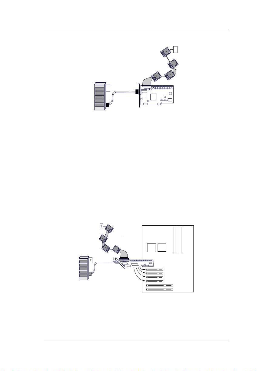
Figure 5. Conne cti ng I nt e rn al and External Drive s
9. Connect a wide, round, 68-pin Very High Density Connector Interface
(VHDCI) cable to the external SCSI connector on the AcceleRAID 150
or 250 and connect the other end of the cable to an external drive
cabinet as required. See Figure 5. External drive cabinets usually have
termination built into the end of the SCSI bus. Check the
documentation that comes with your drive cabinet to be sure this is the
case. If not, use an active terminator at the end of the bus.
☛
Note
An AcceleRAID 150 or 250 automatically determines
whether or not its own on-board termination is
required, and automatically enables or disables onboard termination as necessary.
System Board
Plug Controller into
any Available PCI
Slot
Figure 6. AcceleRAID 150 or 250 in a Typical Standard Installation
The hardware portion of the standard installation is complete.
Continue on to “RAID Configuration” on page 11.
Manual No. 775030 5
Page 12

Performing a SCSI Interrupt Steering Logic (SISL) Installation
JP
Performing a SCSI Interrupt Steering Logic (SISL)
Installation
m Caution
If an operating system or existing data resides on
drives connected to the system board’s resident SCSI
channels, a full backup must be performed on these
drives prior to this installation, as these drives will no
longer be readable after this installation is performed.
1. Be sure power is turned off and the system is not plugged into an
electrical outlet.
,
WARNING
To avoid electrical shock, do not attempt to
perform this hardware installation with power on.
Disconnect the system from the electrical wall
outlet.
2. If JP10 on the AcceleRAID 150 or 250 is not installed, install it, as
shown in Figure 1 and Figure 2. On the AcceleRAID 200 JP10 is
permanently installed, as shown in Figure 7.
4
JP1
JP10
Figure 7. AcceleRAID 200 with Component Locations
6 AcceleRAID 150/200/250 Quick Installation Guide
JP5
Page 13

Table 3. AcceleRAID 200 Jumpers
Jumpers Description
JP1 Header for SCSI activity & Cache Dirty LEDs
JP4 Mylex use only
JP5 Not used
JP10 On for SISL – Off for standard
CC
V
JP1,
LED
Connector
Channel
Activity
LED*
Cache
Dirty
LED*
*Activelow
Figure 8. Pinout for JP1 on the AcceleRAID 200
m Caution
Before you Continue: If the SCSI channels
embedded on the system board are controlled by a
Symbios Logic
disabled in the system BIOS before proceeding with
RAID configuration, operating system installation or
driver installation. This is to allow the AcceleRAID to
take over control of the system board's embedded
channels without any conflicts.
®
chipset, the Symbios chips must be
Hardware
The Symbios chipset can be disabled by running the
CMOS setup routine when powering on your system
(see the documentation that is furnished with your
system).
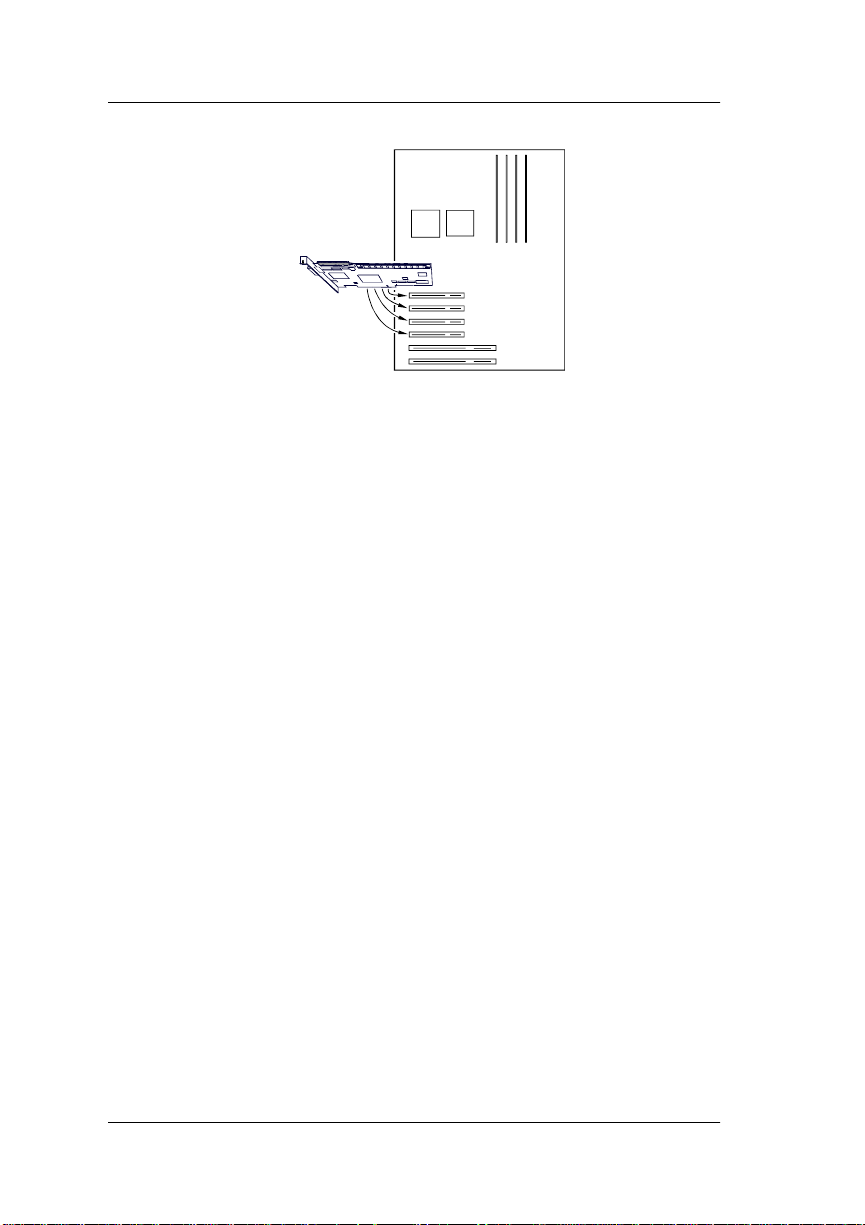
3. Plug the AcceleRAID card into the specially prewired SISL PCI slot.
See the documentation provided with your system board to locate this
special PCI slot (see Figure 9).
☛
Note
When an AcceleRAID 150 or 250 is plugged into the
SISL PCI slot, the channel on the controller
automatically assumes the address of Channel 0. The
addresses of the channels on the system board are
pushed out by one.
Manual No. 775030 7
Page 14

Performing a SCSI Interrupt Steering Logic (SISL) Installation
System Board
Narrow
Plug Controller into
the Specially Wired
SISL PCI Slot
Wide SCSI
Connector
on System
Board
SCSI
Connector
on System
Board
Figure 9. Plugging the AcceleRAID into a Prewired SISL PCI Slot
4. For each channel, set the SCSI ID on each internal drive to a unique
address between 0 and 15, but do not use address 7, as it is reserved for
the controller. See the documentation that comes with your drives for
instructions on how to do this.
m Caution
If internal and external driv es are used, be sure that no
drive addresses on a given channel are duplicated.
External SCSI cabinets usually automatically assign
drive addresses according to where in the cabinet the
drives are located.
5. Be sure termination is disabled on all disk drives connected to the
controller or connected to the system board. See the documentation that
comes with your drives for instructions on how to do this.
6. Be sure that termination power is enabled on all disk drives connected
to the controller or connected to the system board. See the
documentation that comes with your drives for instructions on how to
do this.
7. Connect a wide, 68-pin, high-density SCSI ribbon cable to the internal
SCSI connector on the AcceleRAID 150 or 250 and connect the other
cable connectors to any internal SCSI drives as requir ed. See Figure 10.
8 AcceleRAID 150/200/250 Quick Installation Guide
Page 15

Hardware
T
T
Figure 10. Connecting Internal and External Drives
8. Connect an active terminator to the end of the SCSI ribbon cab le at the
end farthest from the controller. See Figure 10.
9. Connect a wide, round, 68-pin VHDCI cable to the external SCSI
connector on the AcceleRAID 250 and connect the other end of the
cable to an external drive cabinet as required. See Figure 10. External
drive cabinets usually have termination built into the end of the SCSI
bus.
10. Connect a wide, 68-pin, high-density SCSI ribbon cable to the SCSI
connector on the system board and connect the other cable connectors
to any internal SCSI drives as required.
☛
Note
If a narrow SCSI connector is available on the system
board, this should be used for non-disk SCSI
peripherals, such as tape or CDROM drives which
will not be a part of a RAID array.
Manual No. 775030 9
Page 16

Performing a SCSI Interrupt Steering Logic (SISL) Installation
Channel 0
T
Plug Controller into
the Specially Wired
SISL PCI Slot
System Board
Wide SCSI
Connector
on System
Board
(Ch 1)
T
Narrow
SCSI
Connector
on System
Board (Ch 2)
Figure 11. AcceleRAID 150 or 250 in a Typical SISL Installation
T
Narrow
SCSI
Connector
on System
Board (Ch 2)
Plug Controller into
the Specially Wired
SISL PCI Slot
System Board
Wide SCSI
Connector
on System
Board
(Ch 1)
Figure 12. AcceleRAID 200 in a Typical SISL Installation
The hardware portion of the SISL installation is complete.
Continue on to “RAID Configuration” on page 11.
10 AcceleRAID 150/200/250 Quick Installation Guide
Page 17

RAID Configuration
Using RAID EzAssist
RAID EzAssist, the on-board BIOS Configuration Utility is used to build
several types of RAID configurations. Since this is a Quick Installation
Guide, only the Automatic Configuration option will be describ ed here.
☛
Note
A first time installation is being assumed.
The following limitations apply to Automatic C on figuration:
• Only one array will be configured using the Automatic Configuration
option.
• All drives being controlled by the AcceleRAID board can be different
sizes, but will all be formatted to the size of the smallest disk controlled
by the AcceleRAID board.
• A maximum of 7 drives can be configured into an array using
Automatic Configuration. Any additional drives will become hot
spares. The drives with the largest capacity (if mixed drive sizes are
used) will be the drives selected to become hot spares.
☛
Note
If you want to do anything other than an automatic
configuration, refer to the RAID EzAssist
Configuration Utility User Reference Guide.
To perform a RAID configuration with the Automatic Configuration option
using RAID EzAssist, do the following:
1. First power on any disk enclosures connected to the AcceleRAID
controller, and then power on the computer. The AcceleRAID
controller is furnished with the BIOS enabled by default.
2. Watch the messages on the screen for the following prompt to be
displayed:
Press <ALT-M> for BIOS options
Wait approximately 5 seconds. Do not press any keys at this time.
Manual No. 775030 11
Page 18

Using RAID EzAssist
☛
Note
If the BIOS has been disabled on the controller, You
will need to press Alt–M to enable it (See your
controller’s Installation Guide for details).
3. Watch the messages on the screen for the following prompt to be
displayed:
Press <ALT-R> for RAID Configuration options
4. Press Alt–R to get into RAID EzAssist (the configuration utility).
☛
Note
For more detailed information on how to run the
RAID EzAssist, refer to the RAID EzAssist
Configuration Utility User Reference Guide (P/N
775029), which is included on the distribution
CDROM.
The utility will scan all available drive channels for SCSI devices. Upon
completion of the scan, the following will occur under the following
conditions:
a. More than one controller:
Select Controller
will appear on the screen. In this case use the arrow keys to select
the controller you wish to configure and press Enter. This causes
condition b
b. Either one controller, or a controller was selected in a, and no
RAID configuration exists:
No existing RAID configuration has been detected.
Would you like to configure a RAID drive now?
[Yes] No
Select Yes with the arrow keys and Press Enter. Thi s takes you to
step 5.
12 AcceleRAID 150/200/250 Quick Installation Guide
Page 19

RAID Configuration
5. The following options appear:
Automatic
Assisted
Custom
Select Automatic. Press Enter.
☛
Note
The Scope of this Quick Reference Guide only cov ers
Automatic Configuration. For information on
performing Assisted or Custom RAID configurations,
refer to the RAID EzAssist Configuration Utility User
Reference Guide (P/N 775029).
A summary display of the configuration will appear. Up to 5 lines will be
displayed. If more than 5 SCSI drives are physically connected to the
controller, press Page Down to see up to 5 more lines.
6. Select Apply. Press Enter.
The Array will be automatically configured. The program will indicat e that
Automatic Configuration is in progress until the configuration finishes.
Upon completion, the following prompt will be displayed:
RAID drive configuration is successful.
You may utilize this drive immediately.
[Reboot] Main Menu
7. Select Main Menu and press Enter if you want to further examine the
configuratio n.
Or Select Reboot and press Enter to restart your system.
Go on to “Operating Systems and Drivers” on page 14.
Manual No. 775030 13
Page 20

Operating Systems and Drivers
NetWare
Installing the Mylex Disk Array Controller as the Primary NetWare 4.11/4.2 Controller
If the Mylex Disk Array Controller will be the primary (bootable) controller,
you must install the controller driver at the time of NetWare 4.11/4.2
installation.
The procedure below assumes that the CD-ROM drivers are available.
1.Boot the system from a newly created DOS boot drive, and then create
(or edit) the CONFIG.SYS and AUTOEXEC.BAT files to include the
drivers required for accessing the CD-ROM as a logical drive under
DOS. The following example assigns the CD-ROM as drive D: under
MS-DOS 6.00 or above. CONFIG.SYS contains the statements:
device = [pathname]\aspidac.sys
device = [pathname]\btcdrom.sys /D:[devicename]
AUTOEXEC.BAT contains the statement:
[pathname]\mscdex /v /m:10 /D:[devicename]
The device name is that of the specific CD-ROM drive
(e.g., MSCD001).
2.Boot the system with the new CONFIG.SYS and AUTOEXEC.BAT,
and make sure the NetWare CD-ROM files are accessible under DOS.
3.Follow the standard NetWare 4.11/4.2 upgrade or installation
procedure, as described in the NetWare 4.11/4.2 documentation.
4.Insert the NT/NW drivers diskette into the floppy disk drive when the
installation program prompts you to insert the vendor-supplied disk.
The installation program will scan the diskette for all available drivers.
Select the NetWare 4.11/4.2 driver from the list.
MDAC.HAM
14 AcceleRAID 150/200/250 Quick Installation Guide
Page 21

Operating Systems and Drivers
5. After the NetWare 4.11/4.2 installation is complete, copy the files in
the \NW subdirectory of the NT/NW drivers diskette to SYS:SYSTEM
of the NetWare 4.11/4.2 server.
To install GAM server, refer to the Disk Array Controller Software Kit
Installation Guide and User Manual (P/N 771929). To install th e GAM
client, refer to the Global Array Manager Client Software Installation Guide
and User Manual (P/N 771961).
Installing the Mylex Disk Array Controller into an Existing NetWare 4.11/4.2 System
If NetWare 4.11/4.2 is already installed and you wish to add a Mylex Disk
Array Controller later, the controller will be a secondary (non-bootable)
controller. After installing the controller hardware and configuring a disk
array, follow the procedure below to add the necessary controller drivers.
1. With NetWare Server 4.11/4.2 loaded and running, load the NetWare
program INSTALL.NLM by typing the following at the console
prompt:
: load install
and press <Enter>.
2. Choose “Driver Options” in the Installation Options menu.
3. Choose “Configure disk and storage device drivers” in the Driver
Options menu.
4. Choose “Select an additional driver” in the Additional Driver Actions
menu.
NetWare scans for controllers that do not have drivers already loaded.
5. At the “Select a driv er” box, press <I ns> to choose to install an unlisted
driver.
6. Insert the NT/NW drivers diskette into the diskette drive.
7. Press <F3> to specify the path of the NetWare driver you’re about to
install.
Manual No. 775030 15
Page 22

NetWare
8. Change the path line to read:
A:\nw
and press <Enter>. NetWare scans for drivers on the floppy diskette in
the specified path.
9. In the “Select a driver to install” box, select the following driver:
MDAC.HAM | Mylex Disk Array Controller HAM Driver
10. Select Yes at the confirmation box to install the driver.
11. Press <Enter> to select the default server boot path.
12. Select Yes to save a backup of the old or existing driver.
13. Press <Enter> to continue when you see the message that the old
driver will be saved.
NetWare copies the file.
14. What you just backed up was the old or existing .DSK file. Repeat
Steps 12 and 13 for the .DDI file.
15. Select No to decline selection of an additional driver to install.
16. Exit INSTALL.NLM by pressing <Esc> three times, then selecting Yes
at the “Exit Install?” box.
This concludes installation of the driver files needed to run your Mylex Disk
Array Controller under NetWare 4.11/4.2.
For more detailed information on operating system, driver installation, and
GAM Server, see the Disk Array Controller Software Kit Installation Guide
and User Manual (P/N 771929). To install the GAM client, refer to the
Global Array Manager Client Software Installation Guide and User Manual
(P/N 771961).
16 AcceleRAID 150/200/250 Quick Installation Guide
Page 23

Operating Systems and Drivers
Overview of NetWare 5.0
This section provides information about the following:
• Installation procedures and the functionality of the Mylex Disk Array
Controller drivers for No vell NetWare 5.0. The software is provided on
the appropriate Software Kit distribution diskette.
• Installation, verification, and startup of the Global Array Manager
Server software and utilities for Novell NetWare 5.0. The software is
provided on the appropriate GAM Server distribution diskettes.
Mylex Disk Array Controller Driver Files for NetWare
All hardware installation, system configuration, and disk array controller
configuration must be properly completed before proceeding with the
NetWare driver installation. These basic installation procedures follow the
Novell Installation manual, with only the few minor differences that are
described in this section, Netware 5.0.
The subdirectory \NW on the NT/NW driv ers disk ette contains the fo llo wing:
MDA C.HAM: The driver to support Mylex Disk Array Controllers
with NetWare 5.0.
MDAC.DDI: NetWare installation file for MDAC .HAM.
Tape and CD-ROM Support
Tape drive support is available to the Mylex Disk Array Controller under
NetWare by means of the NWASPI driver module that provides ASPI
compatibility. Most NetWare applications that communicate through ASPI
on the server will work with the controller.
Similar to tape drive support, CD-ROM is also supported by the controller
for use under NetWare. The NWASPI driver module must first be loaded to
provide ASPI support to the CD-ROM application running on the server. An
NWASPI driver and a CD-ROM driver will also have to be loaded. These are
included with the Novell NetWare releases.
Manual No. 775030 17
Page 24

Mylex Disk Array Controller Driver for NetWare 5.0
Mylex Disk Array Controller Driver for
NetWare 5.0
Installing the Mylex Disk Array Controller as the Primary NetWare 5.0 Controller
If the Mylex Disk Array Controller will be the primary (bootable) controller,
you must install the controller driver at the time of NetWare 5.0 installation.
Installing NetWare 5.0 Drivers
NetW are version 5.0 is av ailable on CD-R OM. Drivers provided in the \DOS
subdirectory of the Software Kit Distribution diskette (packaged with the
Mylex Disk Array Controller and Disk Array Controller Configuration
Utility manual) are required to install NetWare 5.0 from a CD-ROM drive
connected to a Mylex Disk Array Controller.
The procedure below assumes that the CD-ROM drivers are available.
1. Boot the system from a newly created DOS boot drive, and then create
(or edit) the CONFIG.SYS and AUTOEXEC.BAT files to include the
drivers required for accessing the CD-ROM as a logical drive under
DOS. The following example assigns the CD-ROM as drive D: under
MS-DOS 6.00 or above. CONFIG.SYS contains the statements:
device = [pathname]\aspidac.sys
device = [pathname]\btcdrom.sys /D:[devicename]
AUTOEXEC.BAT contains the statement:
[pathname]\mscdex /v /m:10 /D:[devicename]
The device name is that of the specific CD-ROM drive
(e.g., MSCD001).
2. Boot the system with the new CONFIG.SYS and AUTOEXEC.BAT,
and make sure the NetWare CD-ROM files are accessible under DOS.
3. Follow the standard NetWare 5.0 upgrade or installation procedure, as
described in the NetWare 5.0 documentation.
• While the files are being copied, a message will appear stating
“matching drivers to hardware devices.”
18 AcceleRAID 150/200/250 Quick Installation Guide
Page 25

Operating Systems and Drivers
4. Watch for the status screen that displays the drivers found for storage
adapters:
• Select Modify
• Select Storage Adapters
• Delete the MDAC.HAM line entries
5. Press the Insert key two times in o rder to add new driv ers from ano ther
source. Insert the NT/NW drivers diskette into the floppy disk drive
when the installation program prompts you to insert the vendorsupplied disk. The installation program will scan the diskette for all
available drivers. Select the NetWare 5.0 driver from the list.
MDAC.HAM
• Select the appropriate location for the new drivers (e.g. floppy, etc.).
• Press Return.
• MDAC.HAM will be added from Software Kit 2.1.
6. After the NetWare 5.0 installation is complete, copy the files in the
\NW subdirectory of the NT/NW drivers diskette to SYS:SYSTEM of
the NetWare 5.0 server.
7. Return to the dri v er summary by pressing the arro w k e y s and select the
option to continue.
8. Netware 5.0 will continue the installation.
9. Watch for another status screen that displays the storage devices
(i.e., SCSIHD.CDM and SCSICD.CDM) and the network drivers:
• Select Modify
• Select Storage Devices
• Press the Insert key
• Select NWASPI.CDM (this driver is required to load GAM)
•Press Enter
• Return to the driver summary by using the arrow keys.
Manual No. 775030 19
Page 26

Mylex Disk Array Controller Driver for NetWare 5.0
Installing Peripherals Under NetWare 5.0
Non-disk peripheral devices, such as tape or CD-ROM drives, can be
installed on any channel of the controller. Each non-disk device will require
a unique SCSI ID, different from any other non-disk de v ice connected to the
controller regardless of the channel.
1. The NetWare 5.0 NWASPI must be loaded. For example:
load nwaspi.cdm
:
☛
Note
NWASPI.CDM must be loaded during startup,
otherwise you will need to copy it from the Novell
distribution CD-ROM.
2. After the nwaspi driver is installed, other appropriate drivers should be
loaded before trying to access the non-disk devices. For example, to
use NetWare's Sbackup utility, do the following:
load mdac.ham
:
load nwaspi
:
load tsa500
:
load tapedai
:
scan for new devices
:
load sbackup
:
Except for the mdac.ham driver, .NLM files are supplied by Novell.
Refer to the Novell documentation for instructions on running Sbackup.
3. Load the following drivers (.NLM) to use a CD-ROM under NetWare
5.0 (the NL M, cdrom, is supplied by Novell):
load mdac.ham
:
load scsicd.cdm
:
load cdrom
:
cd mount [volume name]
:
(in the startup file)
After the CD-ROM is mounted, the volume on the CD-ROM can be
mapped from any workstation and accessed.
20 AcceleRAID 150/200/250 Quick Installation Guide
Page 27

Operating Systems and Drivers
Installing the Mylex Disk Array Controller into an Existing NetWare 5.0 System
If NetWare 5.0 is already installed and you wish to add a Mylex Disk Array
Controller later, the controller will be a secondary (non-bootable) controller.
After installing the controller hardware and configuring a disk array, follow
the procedure below to add the necessary controller drivers.
1. With NetWare Server 5.0 loaded and running, load the NetWare
program by typing the following at the console prompt:
: load nwconfig
and press <Enter>.
2. Choose “Driver Options” in the Installation Options menu.
3. Copy NWASPI.CDM (for GAM support) from the Novell distribution
CD-ROM.
• Be sure you are in this directory; \DRIVERS\STORAGE\ and copy
to this directory; C:\NWSERVER.
• Edit the STARTUP.NCF file by adding NWASPI.CDM.
• Add LOAD NWASPI.CDM right after the line, LOAD
SCSICD.CDM
4. Press the arrow keys to return to installation.
5. Choose “Configure disk and storage device drivers” in the Driver
Options menu.
6. Choose “Select an additional driver” in the Additional Driver Actions
menu.
NetWare scans for controllers that do not have drivers already loaded.
7. At the “Select a driv er” box, press <I ns> to choose to install an unlisted
driver.
8. Insert the NT/NW drivers diskette into the diskette drive.
9. Press <F3> to specify the path of the NetWare driver you’re about to
install.
Manual No. 775030 21
Page 28

Mylex Disk Array Controller Driver for NetWare 5.0
10. Change the path line to read:
A:\nw
and press <Enter>. NetWare scans for drivers on the floppy diskette in
the specified path.
11. In the “Select a driver to install” box, select the following driver:
MDAC.HAM | Mylex Disk Array Controller HAM Driver
12. Select Yes at the confirmation box to install the driver.
13. Press <Enter> to select the default server boot path.
14. Select Yes to save a backup of the old or existing driver.
15. Press <Enter> to continue when you see the message that the old
driver will be saved.
NetWare copies the file.
16. What you just backed up was the old or existing .DSK file. Repeat
Steps 12 and 13 for the .DDI file.
17. Select No to decline selection of an additional driver to install.
18. Exit INSTALL.NLM by pressing <Esc> three times, then selecting Yes
at the “Exit Install?” box.
This concludes installation of the driver files needed to run your Mylex Disk
Array Controller under NetWare 5.0.
For more detailed information on operating system, driver installation, and
GAM Server, see the Disk Array Controller Software Kit Installation Guide
and User Manual (P/N 771929). To install the GAM client, refer to the
Global Array Manager Client Software Installation Guide and User Manual
(P/N 771961).
22 AcceleRAID 150/200/250 Quick Installation Guide
Page 29

Operating Systems and Drivers
Windows NT
Installing the Mylex Disk Array Controller as the Primary Windows NT 4.x Controller
If the Mylex Disk Array Controller will be the primary (bootable) controller,
you must install the controller driver at the time of Windows NT 4.x
installation.
Before proceeding you should have already carried out the following steps:
• Installed the Mylex Disk Array Controller hardware, connected the
disk drives to the controller and to each other, set drive SCSI IDs, and
terminated the SCSI bus following the instructions in your Mylex Disk
Array Controller hardware installation guide.
• Use the Mylex Disk Array Controller Configuration Utility to create a
drive configuration and initialize the drives for use following the
instructions in your Mylex Disk Array Controller Configuration Utility
manual.
To install the controller driver during Windows NT 4.x installation:
1. Boot the system with the Windows NT 4.x setup diskette #1.
2. Insert setup diskette #2 when prompted and press <Enter>.
3. Press <Enter> again when prompted.
4. Select Custom Setup in the Windows NT Setup screen.
5. Next, choose S to skip the automatic detection scan.
6. Choose S to specify an additional device.
7. Choose Other in the list of supported adapters displayed and press
<Enter>.
8. When prompted for the Manufacturer’s supplied hardware support
disk, insert the NT/NW drivers diskette into the floppy disk drive and
press <Enter>.
9. Select the Mylex Disk Array Controller Driver in the list and press
<Enter>.
10. Choose S to specify an additional device.
11. Choose Other in the list of supported adapters displayed and press
<Enter>.
Manual No. 775030 23
Page 30

Windows NT
12. With the Software Kit diskette still in the floppy disk drive, press
<Enter>.
13. Select the Mylex Accelerated Disk Driver in the list and press
<Enter>.
14. If you have drivers to install for other controllers (for example, an onboard SCSI controller to run other devices such as a CD-ROM drive,
etc.), repeat Step 6 and Step 7. Then when prompted, insert the
manufacturer’s supplied hardware support disk, press <Enter>, and
select the appropriate driver from the list.
If you have no other drivers to install, or when you have finished
installing other drivers, simply press <Enter> to continue installation.
15. Insert Windows NT 4.x setup diskette #3 when prompted.
16. Follow the on-screen instructions to continue Windows NT 4.x
installation, inserting the Windows NT CDROM into the CDROM
drive when prompted. Press <Enter> and continue with the next few
Windows NT 4.x installation screens.
17. When prompted again for the “DAC960 Software Kit” diskette, insert
the NT/NW drivers diskette into the floppy disk drive and press
<Enter>.
If you installed other drivers from other diskettes, you will be asked to
reinsert those diskettes as well.
This concludes Mylex Disk Array Controller driver installation for Windows
NT 4.x. Follow the on-screen instructions to complete your installation of
the Windows NT 4.x operating system.
For more detailed information on operating system, driver installation, and
GAM Server, see the Disk Array Controller Software Kit Installation Guide
and User Manual (P/N 771929). To install the GAM client, refer to the
Global Array Manager Client Software Installation Guide and User Manual
(P/N 771961).
24 AcceleRAID 150/200/250 Quick Installation Guide
Page 31

Operating Systems and Drivers
Installing the Mylex Disk Array Controller into an Existing Windows NT 4.x System
If Windows NT 4.x is already installed and you wish to add a Mylex Disk
Array Controller later, the controller will be a secondary (non-bootable)
controller. After installing the controller hardware and configuring a disk
array, follow the procedure below to add the necessary controller drivers.
1. Make sure Windows NT 4.x is up and running.
2. Click Start, and select Settings->Cont r ol P ane l within the Start menu.
3. From the Control Panel window, double-click the SCSI Adapters icon.
4. In the SCSI Adapters box, click the Drivers tab to bring the Drivers
page to the foreground.
5. With the Drivers page in the foreground, click Add.
6. The Creating driver list progress bar is displayed briefly, and then the
Install Driver box is displayed.
7. In the Install Driver box, click Have Disk.
8. Insert the NT/NW drivers diskette into the floppy disk drive.
9. From the Install From Disk box, change the path to A:\NT and click
OK.
10. From the Install Dr i ver box, be sure the Myle x Disk Array Contro ller is
selected and click OK.
11. If there is an existing Mylex driver in the system you will see a
Windows NT Setup box. Click New to install the new driver from the
diskette.
12. Again, be sure the path is A:\NT and c l ick Continue.
The driver is copied from the diskette. The System Settings Change
box is displayed.
13. Click No at this time, because you will need to install the Mylex
Accelerated Driver before restarting Windows NT 4.x.
14. With the Drivers page in the foreground, click Add.
Manual No. 775030 25
Page 32

Windows NT
15. The Install Driver box is displayed.
In the Install Driver box, click Have Disk.
16. Reinsert the NT/NW drivers diskette into the floppy disk drive if
requested.
17. From the Install From Disk box, change the path to A:\DISK and click
OK.
18. From the Install Driv er box, be sure the Mylex Accelerated Disk Dri v er
is selected and click OK.
19. If there is an existing Mylex driver in the system you will see a
Windows NT Setup box. Click New to install the new driver from the
diskette.
20. Again, be sure the path is A:\DISK and click Co ntinue.
The driver is copied from the diskette. The System Settings Change
box is displayed.
21. Remove the diskette and click Yes to restart Windows NT 4.x for the
new Mylex Disk Array Controller drivers to be available.
For more detailed information on operating system, driver installation, and
GAM Server, see the Disk Array Controller Software Kit Installation Guide
and User Manual (P/N 771929). To install the GAM client, refer to the
Global Array Manager Client Software Installation Guide and User Manual
(P/N 771961).
26 AcceleRAID 150/200/250 Quick Installation Guide
Page 33

Page 34

CorporateOffices
Tel:510.796.6100 SalesFax:510.745.8016 www.mylex.com
EuropeanSales
Tel:44.1344.302200 Fax:44.1344.301100 www.mylex.com
●
34551 Ardenwood Blvd., Fremont, CA94555-3607, USA
●●
●
P.O. Box 513, Great Missenden, Bucks HP 16 OPG, United Kingdom
● ●
Page 35

Page 36

 Loading...